TECHNICAL NOTES on Brick Construction12007 Sunrise Valley Drive, Suite 430, Reston, Virginia 20191 | www.gobrick.com | 703-620-0010
18AMay 2019
Accommodating Expansion of BrickworkAbstract: Expansion joints are used in brickwork to accommodate movement and to avoid cracking. This Technical Note describes typical movement joints used in building construction and gives guidance regarding their placement. The theory and rationale for the guidelines are presented. Examples are given showing proper placement of expansion joints to avoid cracking of brickwork and methods to improve the aesthetic impact of expansion joints. Also included is information about bond breaks, bond beams and flexible anchorage.
Vertical Expansion Joints in Brick Veneer:• For brickwork without openings, space no more than 25 ft
(7.6 m) o.c.• For brickwork with multiple openings, consider
symmetrical placement of expansion joints and reduced spacing of no more than 20 ft (6.1 m) o.c.
• When spacing between vertical expansion joints in parapets is more than 15 ft (4.6 m), make expansion joints wider or place additional expansion joints halfway between full-height expansion joints
• Place as follows:• at or near corners• at offsets and setbacks• at wall intersections• at changes in wall height• where wall backing system changes• where support of brick veneer changes• where wall function or climatic exposure changes
• Extend to top of brickwork, including parapets
Horizontal Expansion Joints in Brick Veneer:• Locate immediately below shelf angles• Minimum ¼ in. (6.4 mm) space or compressible material
recommended below shelf angle• For brick infill, place between the top of brickwork and
structural frame
Brickwork Without Shelf Angles:• Accommodate brickwork movement by:
• placing expansion joints around elements that are rigidly attached to the frame and project into the veneer, such as windows and doorframes
• installing metal caps or copings that allow independent vertical movement of wythes
• installing jamb receptors that allow independent movement between the brick and window frame
• installing adjustable anchors or ties
Expansion Joint Sealants:• Comply with ASTM C920, Grade NS, Use M• Class 50 minimum compressibility recommended;
Class 25 alternate• Consult sealant manufacturer’s literature for guidance
regarding use of primer and backing materials
Bond Breaks:• Use building paper, flashing, or 4 to 6 mil thick
polyethylene sheeting to separate brickwork from dissimilar materials, foundations and slabs
Load-Bearing Masonry:• Use reinforcement to accommodate stress
concentrations, particularly in parapets, at applied loading points and around openings
• Consider effect of vertical expansion joints on brickwork stability
SUMMARY OF RECOMMENDATIONS:
INTRODUCTIONA system of movement joints is necessary to accommodate the changes in volume that all building materials experience. Failure to permit the movements caused by these changes may result in cracks in brickwork, as discussed in Technical Note 18. The type, size and placement of movement joints are critical to the proper performance of a building. This Technical Note defines the types of movement joints and discusses the proper design of expansion joints for brickwork. Details of expansion joints are provided for load-bearing and non-load-bearing applications. Movement joints are typically included in the design of commercial and multistory structures and, although rare, must also be considered for residential structures.
www.gobrick.com | Brick Industry Association | TN 18A | Accommodating Expansion of Brickwork | Page 2 of 13
TYPES OF MOVEMENT JOINTSThe primary type of movement joint used in brick construction is the expansion joint. Other types of movement joints in buildings include control joints, building expansion joints and construction (cold) joints. Each of these is designed for a specific application, and they should not be used interchangeably. It is important to understand the proper function of each movement joint, as improper application will prevent the joint from functioning properly and may result in damage to the masonry.
An expansion joint prevents cracking by separating brick masonry into segments, reducing the cumulative effects of movements caused by changes in temperature, moisture expansion, elastic deformation, settlement and creep. Expansion joints may be horizontal or vertical. The joints are formed by leaving a continuous unobstructed opening through the brick wythe that may be filled with a highly compressible material. This allows the joints to partially close as the brickwork expands. Expansion joints must be located so the structural integrity of the brickwork is not compromised.
A control joint creates a plane of weakness in concrete or concrete masonry construction that, in conjunction with reinforcement or joint reinforcement, causes a crack resulting from shrinkage to occur at a predetermined location in a straight line. A control joint is usually a partial depth indentation cut or formed into concrete or a vertical gap through a concrete masonry wythe that may be filled with inelastic materials. A control joint will tend to widen as the concrete or concrete masonry shrinks. Control joints must be located so that the structural integrity of the concrete or concrete masonry is not affected.
A building expansion joint is used to separate a building into discrete sections so stresses developed in one section will not affect the integrity of the entire structure. A building expansion joint extends through the entire wall assembly, other components of the building envelope, and the underlying structure, and is wider than a typical expansion or control joint in a masonry wythe.
A construction joint (cold joint) occurs primarily in concrete construction when construction work is interrupted. Construction joints should be located where they will least impair the strength of the structure.
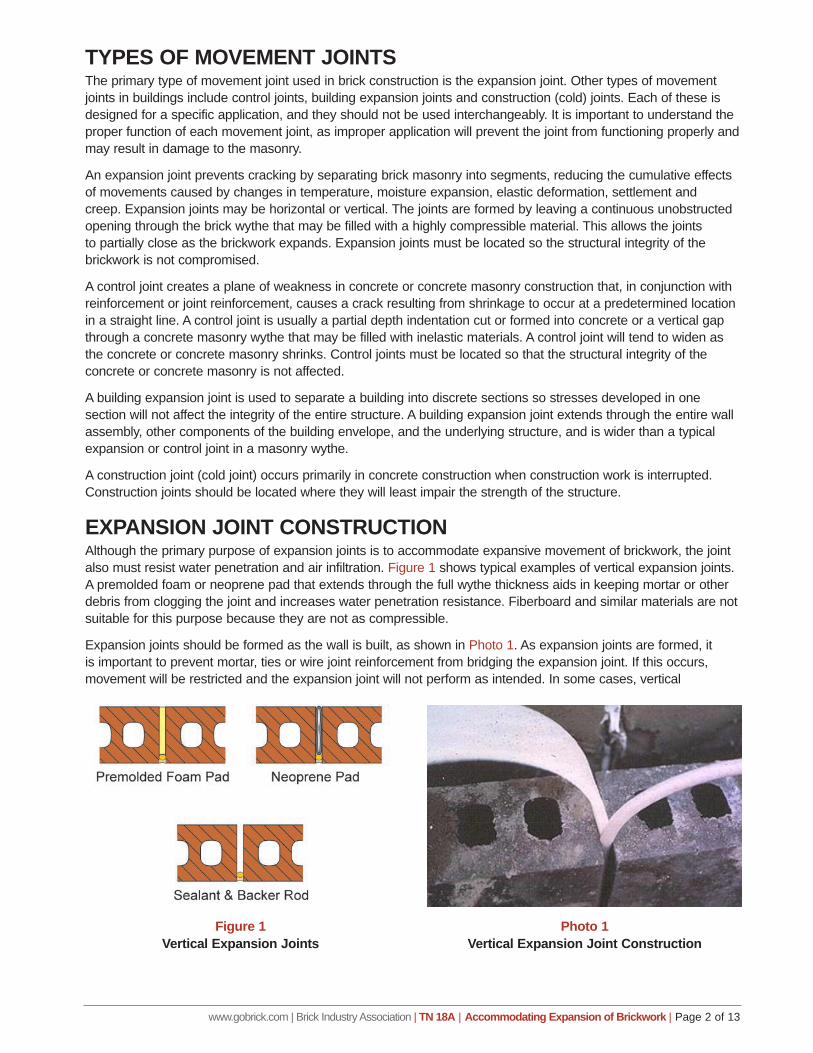
EXPANSION JOINT CONSTRUCTIONAlthough the primary purpose of expansion joints is to accommodate expansive movement of brickwork, the joint also must resist water penetration and air infiltration. Figure 1 shows typical examples of vertical expansion joints. A premolded foam or neoprene pad that extends through the full wythe thickness aids in keeping mortar or other debris from clogging the joint and increases water penetration resistance. Fiberboard and similar materials are not suitable for this purpose because they are not as compressible.
Expansion joints should be formed as the wall is built, as shown in Photo 1. As expansion joints are formed, it is important to prevent mortar, ties or wire joint reinforcement from bridging the expansion joint. If this occurs, movement will be restricted and the expansion joint will not perform as intended. In some cases, vertical
Figure 1Vertical Expansion Joints
Photo 1Vertical Expansion Joint Construction
www.gobrick.com | Brick Industry Association | TN 18A | Accommodating Expansion of Brickwork | Page 3 of 13
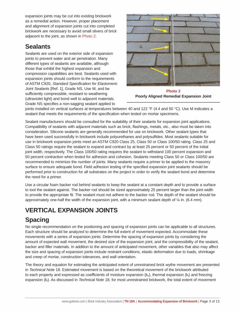
expansion joints may be cut into existing brickwork as a remedial action. However, proper placement and alignment of expansion joints cut into completed brickwork are necessary to avoid small slivers of brick adjacent to the joint, as shown in Photo 2.
SealantsSealants are used on the exterior side of expansion joints to prevent water and air penetration. Many different types of sealants are available, although those that exhibit the highest expansion and compression capabilities are best. Sealants used with expansion joints should conform to the requirements of ASTM C920, Standard Specification for Elastomeric Joint Sealants [Ref. 1], Grade NS, Use M, and be sufficiently compressible, resistant to weathering (ultraviolet light) and bond well to adjacent materials. Grade NS specifies a non-sagging sealant applied to joints installed on vertical surfaces at temperatures between 40 and 122 °F (4.4 and 50 °C). Use M indicates a sealant that meets the requirements of the specification when tested on mortar specimens.
Sealant manufacturers should be consulted for the suitability of their sealants for expansion joint applications. Compatibility of sealants with adjacent materials such as brick, flashings, metals, etc., also must be taken into consideration. Silicone sealants are generally recommended for use on brickwork. Other sealant types that have been used successfully in brickwork include polyurethanes and polysulfides. Most sealants suitable for use in brickwork expansion joints meet an ASTM C920 Class 25, Class 50 or Class 100/50 rating. Class 25 and Class 50 ratings require the sealant to expand and contract by at least 25 percent or 50 percent of the initial joint width, respectively. The Class 100/50 rating requires the sealant to withstand 100 percent expansion and 50 percent contraction when tested for adhesion and cohesion. Sealants meeting Class 50 or Class 100/50 are recommended to minimize the number of joints. Many sealants require a primer to be applied to the masonry surface to ensure adequate bond. Field adhesion testing of the specified expansion joint sealants should be performed prior to construction for all substrates on the project in order to verify the sealant bond and determine the need for a primer.
Use a circular foam backer rod behind sealants to keep the sealant at a constant depth and to provide a surface to tool the sealant against. The backer rod should be sized approximately 25 percent larger than the joint width to provide the appropriate fit. The sealant must not adhere to the backer rod. The depth of the sealant should be approximately one-half the width of the expansion joint, with a minimum sealant depth of ¼ in. (6.4 mm).
VERTICAL EXPANSION JOINTSSpacingNo single recommendation on the positioning and spacing of expansion joints can be applicable to all structures. Each structure should be analyzed to determine the full extent of movement expected. Accommodate these movements with a series of expansion joints. Determine the spacing of expansion joints by considering the amount of expected wall movement, the desired size of the expansion joint, and the compressibility of the sealant, backer and filler materials. In addition to the amount of anticipated movement, other variables that also may affect the size and spacing of expansion joints include restraint conditions, elastic deformation due to loads, shrinkage and creep of mortar, construction tolerances, and wall orientation.
The theory and equation for estimating the anticipated extent of unrestrained brick wythe movement are presented in Technical Note 18. Estimated movement is based on the theoretical movement of the brickwork attributed to each property and expressed as coefficients of moisture expansion (ke), thermal expansion (kt) and freezing expansion (kf). As discussed in Technical Note 18, for most unrestrained brickwork, the total extent of movement
Photo 2 Poorly Aligned Remedial Expansion Joint
www.gobrick.com | Brick Industry Association | TN 18A | Accommodating Expansion of Brickwork | Page 4 of 13
can be estimated as the length of the brickwork multiplied by 0.0009. A derivative of this equation can be written to calculate the theoretical spacing between vertical expansion joints as follows:
Se =
wjej Eq. 1 0.09
where:Se = spacing between expansion joints, in. (mm)wj = width of expansion joint, typically the mortar joint width, in. (mm)ej = percent compressibility of expansion joint material (least of sealant, backer and filler)
The expansion joint is typically sized to resemble a mortar joint, usually ⅜ in. (10 mm) to ½ in. (13 mm). The width of an expansion joint may be limited by the sealant capabilities. Compressibility of modern sealants in the 25 to 50 percent range is typical for brickwork.
Example. Consider a typical brick veneer with a desired expansion joint size of ½ in. (13 mm) and a sealant with 50 percent compressibility. Equation 1 gives the following theoretical expansion joint spacing:
Se =
(0.5 in.)(50) = 278 in. or 23 ft, 2 in. (7.06 m)
0.09
Therefore, the maximum theoretical spacing between vertical expansion joints in a straight wall would be 23 ft, 2 in. (7.06 m). This theoretical spacing does not take into account window openings, corners or properties of other materials that may require a reduction in expansion joint spacing. In most instances, it is desirable to be conservative when calculating spacing between joints, but it may be justifiable to exceed the theoretical maximum spacing based on engineering judgment. For example, calculations may result in a theoretical spacing of expansion joints every 23 ft, 2 in. (7.06 m), but the actual expansion joint spacing is set at 24 ft (7.32 m) to match the structural column spacing or a specific modular dimension. Vertical expansion joint spacing should not exceed 25 ft (7.6 m) in brickwork without openings and 20 ft (6.1 m) for brickwork with multiple openings.
PlacementThe actual location of vertical expansion joints in a structure is dependent upon the configuration of the structure, as well as the expected amount of movement. In addition to placing an adequate number of expansion joints within long walls, consider placing expansion joints at areas of natural stress concentration, such as corners, offsets, openings, wall intersections, changes in wall heights, junctions, parapets, material transitions, deflection of supports and deflection of wood.
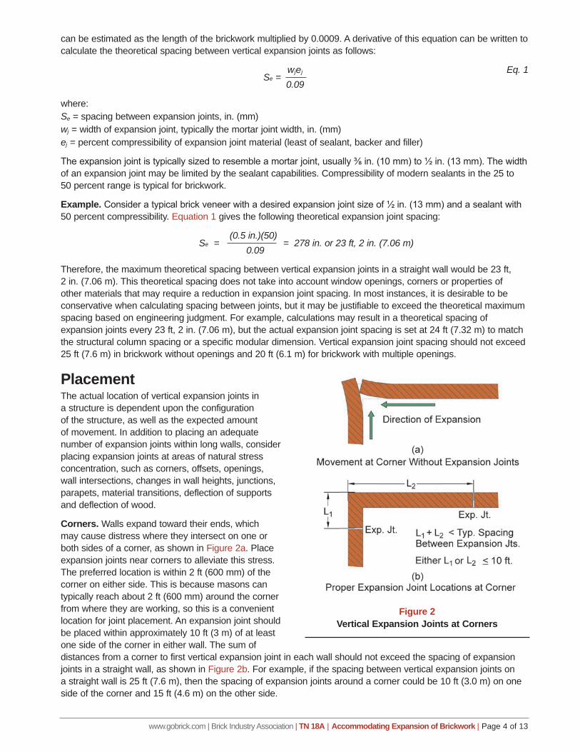
Corners. Walls expand toward their ends, which may cause distress where they intersect on one or both sides of a corner, as shown in Figure 2a. Place expansion joints near corners to alleviate this stress. The preferred location is within 2 ft (600 mm) of the corner on either side. This is because masons can typically reach about 2 ft (600 mm) around the corner from where they are working, so this is a convenient location for joint placement. An expansion joint should be placed within approximately 10 ft (3 m) of at least one side of the corner in either wall. The sum of distances from a corner to first vertical expansion joint in each wall should not exceed the spacing of expansion joints in a straight wall, as shown in Figure 2b. For example, if the spacing between vertical expansion joints on a straight wall is 25 ft (7.6 m), then the spacing of expansion joints around a corner could be 10 ft (3.0 m) on one side of the corner and 15 ft (4.6 m) on the other side.
Figure 2Vertical Expansion Joints at Corners
www.gobrick.com | Brick Industry Association | TN 18A | Accommodating Expansion of Brickwork | Page 5 of 13
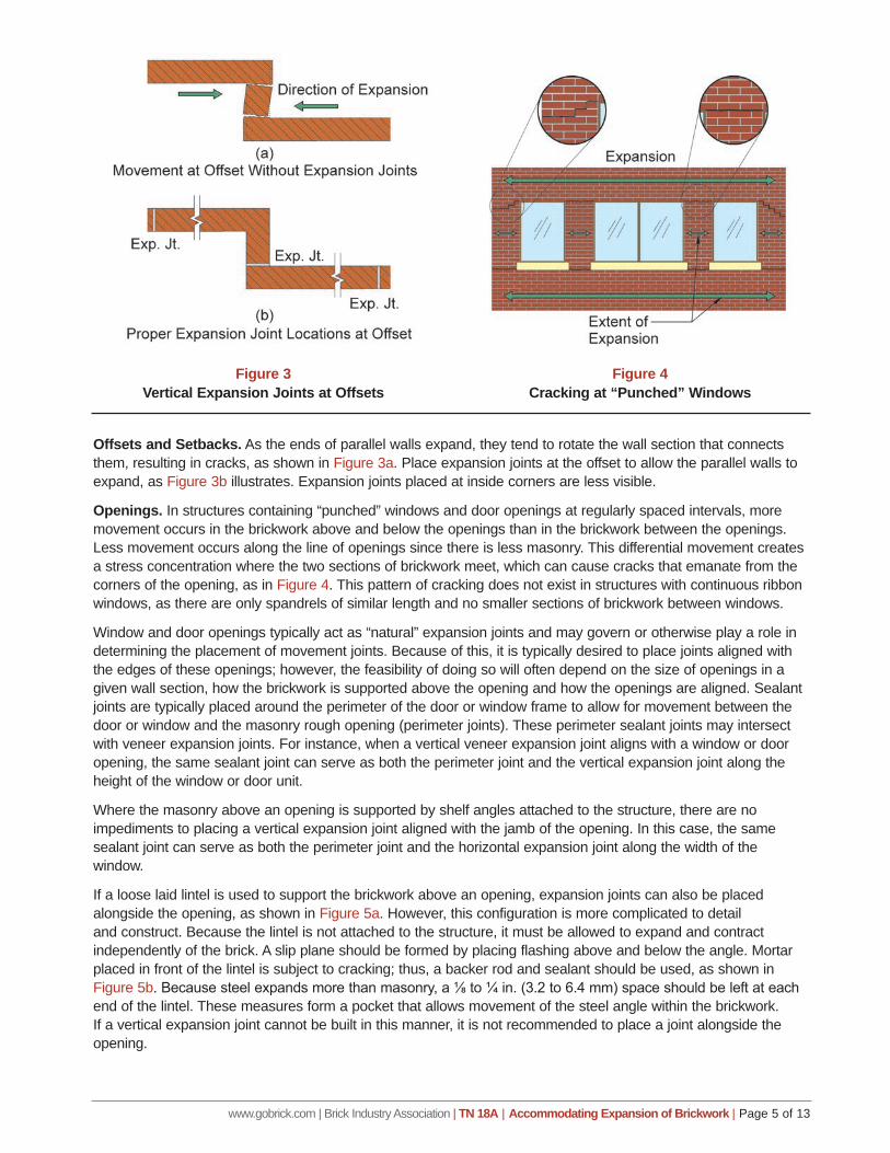
Offsets and Setbacks. As the ends of parallel walls expand, they tend to rotate the wall section that connects them, resulting in cracks, as shown in Figure 3a. Place expansion joints at the offset to allow the parallel walls to expand, as Figure 3b illustrates. Expansion joints placed at inside corners are less visible.
Openings. In structures containing “punched” windows and door openings at regularly spaced intervals, more movement occurs in the brickwork above and below the openings than in the brickwork between the openings. Less movement occurs along the line of openings since there is less masonry. This differential movement creates a stress concentration where the two sections of brickwork meet, which can cause cracks that emanate from the corners of the opening, as in Figure 4. This pattern of cracking does not exist in structures with continuous ribbon windows, as there are only spandrels of similar length and no smaller sections of brickwork between windows.
Window and door openings typically act as “natural” expansion joints and may govern or otherwise play a role in determining the placement of movement joints. Because of this, it is typically desired to place joints aligned with the edges of these openings; however, the feasibility of doing so will often depend on the size of openings in a given wall section, how the brickwork is supported above the opening and how the openings are aligned. Sealant joints are typically placed around the perimeter of the door or window frame to allow for movement between the door or window and the masonry rough opening (perimeter joints). These perimeter sealant joints may intersect with veneer expansion joints. For instance, when a vertical veneer expansion joint aligns with a window or door opening, the same sealant joint can serve as both the perimeter joint and the vertical expansion joint along the height of the window or door unit.
Where the masonry above an opening is supported by shelf angles attached to the structure, there are no impediments to placing a vertical expansion joint aligned with the jamb of the opening. In this case, the same sealant joint can serve as both the perimeter joint and the horizontal expansion joint along the width of the window.
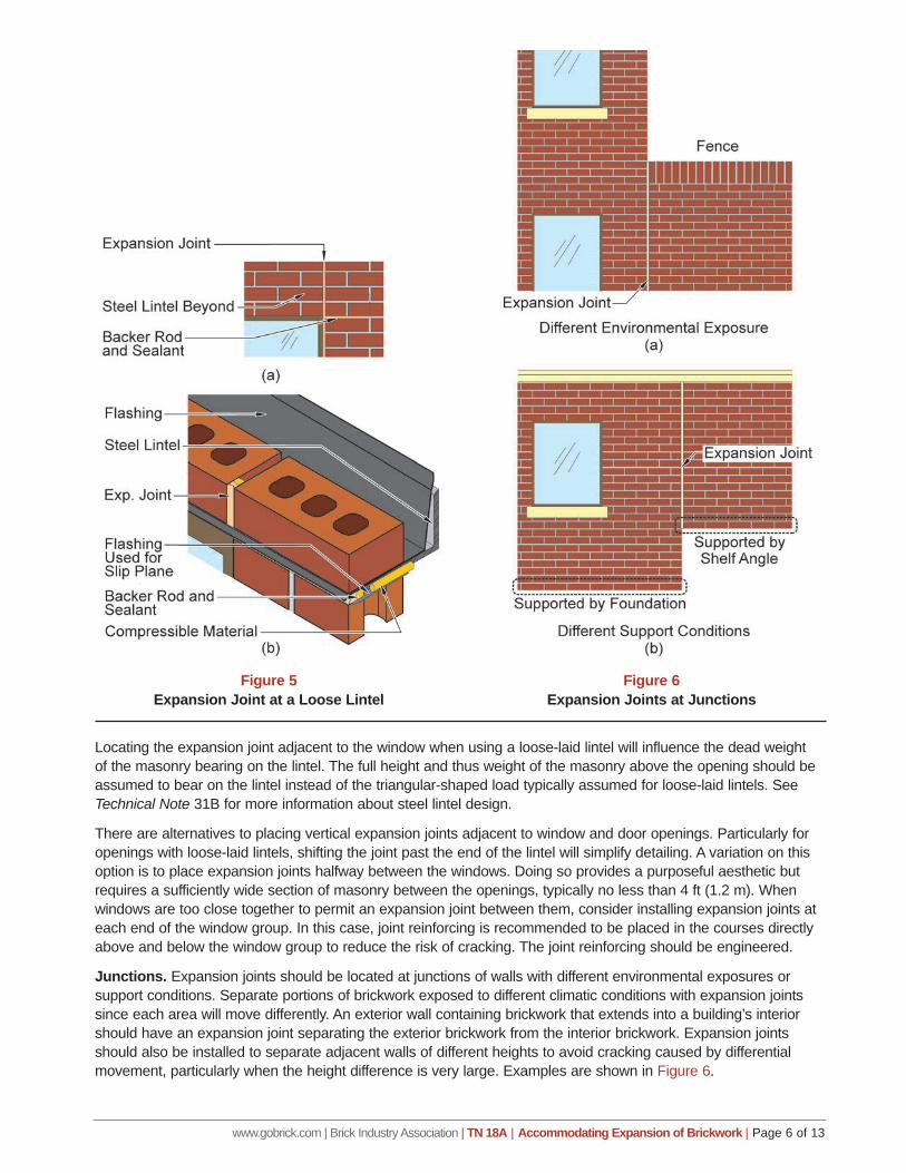
If a loose laid lintel is used to support the brickwork above an opening, expansion joints can also be placed alongside the opening, as shown in Figure 5a. However, this configuration is more complicated to detail and construct. Because the lintel is not attached to the structure, it must be allowed to expand and contract independently of the brick. A slip plane should be formed by placing flashing above and below the angle. Mortar placed in front of the lintel is subject to cracking; thus, a backer rod and sealant should be used, as shown in Figure 5b. Because steel expands more than masonry, a ⅛ to ¼ in. (3.2 to 6.4 mm) space should be left at each end of the lintel. These measures form a pocket that allows movement of the steel angle within the brickwork. If a vertical expansion joint cannot be built in this manner, it is not recommended to place a joint alongside the opening.
Figure 3Vertical Expansion Joints at Offsets
Figure 4Cracking at “Punched” Windows
www.gobrick.com | Brick Industry Association | TN 18A | Accommodating Expansion of Brickwork | Page 6 of 13
Locating the expansion joint adjacent to the window when using a loose-laid lintel will influence the dead weight of the masonry bearing on the lintel. The full height and thus weight of the masonry above the opening should be assumed to bear on the lintel instead of the triangular-shaped load typically assumed for loose-laid lintels. See Technical Note 31B for more information about steel lintel design.
There are alternatives to placing vertical expansion joints adjacent to window and door openings. Particularly for openings with loose-laid lintels, shifting the joint past the end of the lintel will simplify detailing. A variation on this option is to place expansion joints halfway between the windows. Doing so provides a purposeful aesthetic but requires a sufficiently wide section of masonry between the openings, typically no less than 4 ft (1.2 m). When windows are too close together to permit an expansion joint between them, consider installing expansion joints at each end of the window group. In this case, joint reinforcing is recommended to be placed in the courses directly above and below the window group to reduce the risk of cracking. The joint reinforcing should be engineered.
Junctions. Expansion joints should be located at junctions of walls with different environmental exposures or support conditions. Separate portions of brickwork exposed to different climatic conditions with expansion joints since each area will move differently. An exterior wall containing brickwork that extends into a building’s interior should have an expansion joint separating the exterior brickwork from the interior brickwork. Expansion joints should also be installed to separate adjacent walls of different heights to avoid cracking caused by differential movement, particularly when the height difference is very large. Examples are shown in Figure 6.
Figure 5Expansion Joint at a Loose Lintel
Figure 6Expansion Joints at Junctions
www.gobrick.com | Brick Industry Association | TN 18A | Accommodating Expansion of Brickwork | Page 7 of 13
Parapets. Parapets require special treatment due to their differing configuration compared with a typical building wall. A parapet is exposed to moisture and the environment on three sides instead of one, which increases the amount of movement it can experience. A parapet also lacks sufficient dead load from brickwork above to restrain movement. Because of these conditions, additional accommodations for movement are required in parapets. It is recommended to extend all vertical expansion joints through the parapet and place additional parapet expansion joints approximately halfway between those running full height, such that the spacing between joints is no more than 15 ft (4.6 m) apart at the top of the parapet. These parapet expansion joints must continue to a horizontal expansion joint. Usually they will be terminated at the horizontal joint associated with the shelf angle at the roof level. If joint spacing of no more than 15 ft (4.6 m) cannot be achieved, widen the expansion joints. If additional parapet joints cannot be installed, continuous joint reinforcement should be installed at 16 in. (406 mm) o.c. vertically in the parapet.
Material Transitions. Many modern buildings incorporate a variety of cladding materials in their design, with multiple materials present on the same facade. Expansion joints should always be placed at the transitions between brick and non-masonry cladding systems to accommodate the movement of each material. Closure of the brick air space, flashing and drainage between cladding systems is necessary in many cases. Expansion joints are also required between brick and projecting elements such as pipes, vents and ducts. Refer to Technical Note 7 for more information about flashing requirements and recommendations at material transitions. In the case of horizontal joints, increased width to accommodate additional movement due to frame shrinkage may be required.
Masonry Infill. Expansion joints should be placed around masonry infill to isolate it from the surrounding structural frame. The expansion joint along the top course of the infill should accommodate the deflection of the beam, floor or roof system above.
Deflection of Support. Brickwork can be supported by a beam or floor, provided that the maximum deflection of that support is L/600. These spandrel sections of brickwork are subject to stresses from deflection of the support. Reduced spacing between expansion joints will permit deflection to occur without cracking the brickwork.
Support on Wood. Building Code Requirements for Masonry Structures (TMS 402) [Ref. 4] and most building codes allow anchored masonry veneer with an installed weight not exceeding 40 lb/ft2 (1,915 Pa) and a maximum height of 12 ft (3.66 m) to be supported on wood construction, provided that a vertical expansion joint is used to isolate the veneer supported by wood from the veneer supported by the foundation.
Planning Expansion Joint Placement During DesignIt can be difficult to decide where to begin when determining the placement of vertical expansion joints. Starting at a corner and placing joints at the typical spacing around the building perimeter is not a recommended approach. The following approach is suggested, which prioritizes placing joints at known areas of stress concentrations prior to considering maximum recommended spacing.
1. Place joints at transitions between brick and other cladding systems or structures. 2. Place joints at junctions such as changes in support conditions and interfaces between walls of
differing height.3. Place joints at all inside corners (offsets and setbacks) with brick on both sides.4. Place joints near outside corners with brick on both sides, per Figure 2b.5. Where possible, place joints near detailing such as quoins or reveals to minimize their appearance.6. Based on whether the brickwork has openings, determine the maximum spacing between joints,
and place additional joints where needed. It is often preferable to place joints closer together where they have minimal impact on architectural features rather than spacing them at the recommended maximum distance. Joints at closer spacing can be used to create an aesthetic layout.
7. Extend vertical joints through the parapet. When spacing between vertical joints in a parapet is more than 15 ft (4.6 m), either widen the joints or place additional parapet expansion joints as needed to achieve a maximum 15 ft (4.6 m) spacing.
www.gobrick.com | Brick Industry Association | TN 18A | Accommodating Expansion of Brickwork | Page 8 of 13
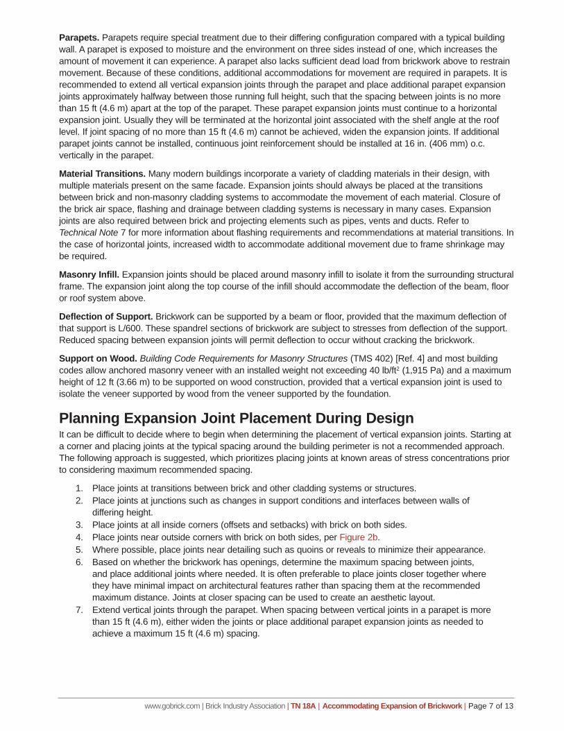
Aesthetic EffectsAlthough expansion joints are usually noticeable on flat walls of masonry buildings, there are ways to reduce their visual impact. Architectural features such as quoins, recessed panels of brickwork or a change in bond pattern reduce the visual impact of vertical expansion joints. In some cases, it may be desirable to accentuate the location of the expansion joint as a design detail. This is possible by recessing the brickwork at the expansion joint or by using special-shaped brick units as shown in Photo 3.
Colored sealants that match the brick in running bond, or the mortar in stack bond, help to hide vertical expansion joints. Mason’s sand also can be rubbed into new sealant to remove the sheen, making the joint blend in more. Expansion joints also are less noticeable when located at inside corners. Hiding expansion joints behind downspouts or other building elements can inhibit maintenance access and is not advised. Installing expansion joints to follow the masonry bond pattern (toothing or zipper joint) is not recommended. Their shape creates difficulty in keeping debris out of the joint during construction; such debris could interfere with movement. In addition, the articulated shape subjects the sealant to both shear and tension combined, which adversely affects the performance of the sealant.
Symmetrical placement of expansion joints on the elevation of buildings is usually most aesthetically pleasing. Further, placing the expansion joints in a pattern such that wall areas and openings are symmetrical between expansion joints will reduce the likelihood of cracking.
HORIZONTAL EXPANSION JOINTSHorizontal expansion joints are typically needed if the brick wythe is supported on a shelf angle attached to the frame or used as infill within the frame. Placing horizontal expansion joints below shelf angles provides sufficient space for vertical expansion of the brickwork below and deformation of the shelf angle and the structure to which it is attached. The joint is formed by leaving an unobstructed space, typically ¼ in. (6 mm) in height, or placing a highly compressible material beneath the angle, and a backer rod and sealant at the toe of the angle to seal the joint. Structures that support the brick wythe on shelf angles, usually at each floor, must have horizontal expansion joints under each shelf angle. Larger sized expansion joints may be required to accommodate the differential movement of taller story heights or where a shelf angle supports more than one story of brickwork. Figure 7 shows a typical detail of a horizontal expansion joint beneath a shelf angle.
If the shelf angle is not attached to the structure when the brick below it are laid, then any temporary shims that support the angle during installation must be removed after the shelf angle is connected. It is not necessary to interrupt shelf angles at vertical expansion joint locations. However, shelf angles must be discontinuous to provide
Photo 3Accentuated Expansion Joint
Figure 7Horizontal Expansion Joint at Shelf Angle
www.gobrick.com | Brick Industry Association | TN 18A | Accommodating Expansion of Brickwork | Page 9 of 13
for their own thermal expansion. A space of ¼ in. in 20 ft (6 mm in 6 m) of shelf angle length is typically sufficient. Bolt heads anchoring a shelf angle to the structure should be covered to decrease the possibility of flashing puncture.
The size of the horizontal expansion joint should take into account movements of the brickwork and movements of the frame. Frame movements include both material and load-induced movements, such as deflections of the shelf angle; rotation of the horizontal leg of the shelf angle; and movement of the support from deflection, temperature change, shrinkage, creep or other factors.
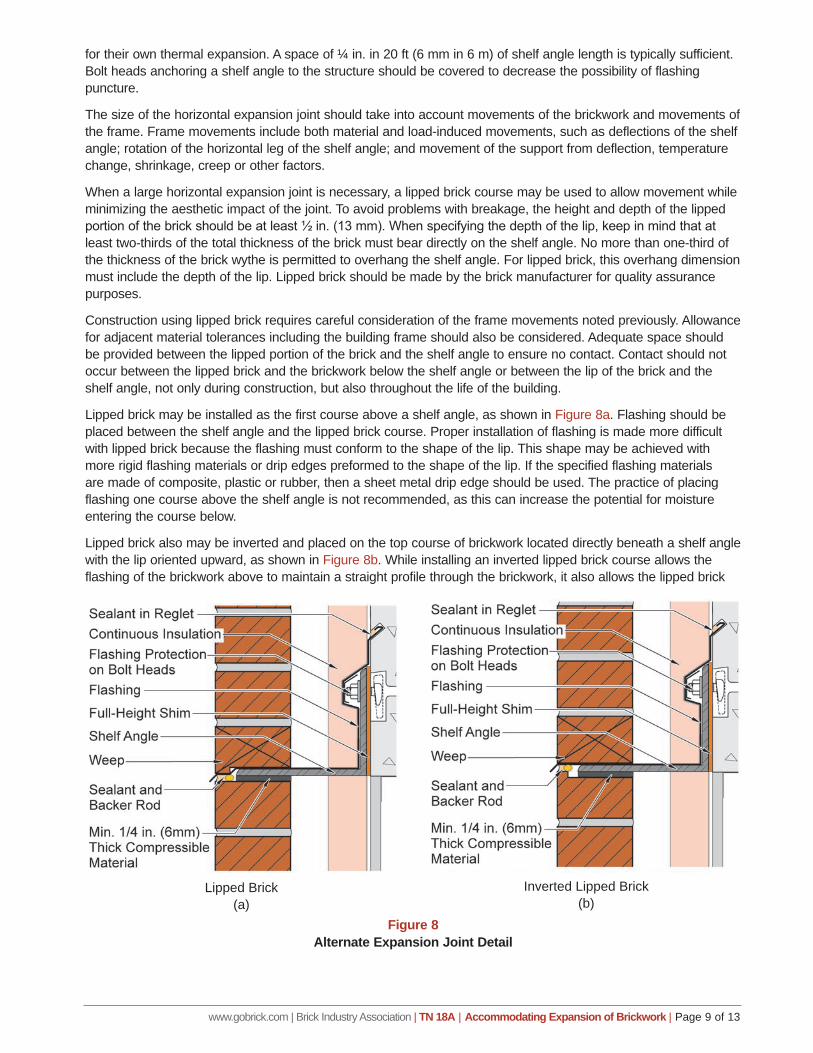
When a large horizontal expansion joint is necessary, a lipped brick course may be used to allow movement while minimizing the aesthetic impact of the joint. To avoid problems with breakage, the height and depth of the lipped portion of the brick should be at least ½ in. (13 mm). When specifying the depth of the lip, keep in mind that at least two-thirds of the total thickness of the brick must bear directly on the shelf angle. No more than one-third of the thickness of the brick wythe is permitted to overhang the shelf angle. For lipped brick, this overhang dimension must include the depth of the lip. Lipped brick should be made by the brick manufacturer for quality assurance purposes.
Construction using lipped brick requires careful consideration of the frame movements noted previously. Allowance for adjacent material tolerances including the building frame should also be considered. Adequate space should be provided between the lipped portion of the brick and the shelf angle to ensure no contact. Contact should not occur between the lipped brick and the brickwork below the shelf angle or between the lip of the brick and the shelf angle, not only during construction, but also throughout the life of the building.
Lipped brick may be installed as the first course above a shelf angle, as shown in Figure 8a. Flashing should be placed between the shelf angle and the lipped brick course. Proper installation of flashing is made more difficult with lipped brick because the flashing must conform to the shape of the lip. This shape may be achieved with more rigid flashing materials or drip edges preformed to the shape of the lip. If the specified flashing materials are made of composite, plastic or rubber, then a sheet metal drip edge should be used. The practice of placing flashing one course above the shelf angle is not recommended, as this can increase the potential for moisture entering the course below.
Lipped brick also may be inverted and placed on the top course of brickwork located directly beneath a shelf angle with the lip oriented upward, as shown in Figure 8b. While installing an inverted lipped brick course allows the flashing of the brickwork above to maintain a straight profile through the brickwork, it also allows the lipped brick
Figure 8Alternate Expansion Joint Detail
Lipped Brick(a)
Inverted Lipped Brick(b)
www.gobrick.com | Brick Industry Association | TN 18A | Accommodating Expansion of Brickwork | Page 10 of 13
course to move independent of the shelf angle. As a consequence, there is an increased possibility of the shelf angle coming in contact with the lipped brick course, resulting in cracking at the lip. When a course of inverted lipped brick is installed, it is difficult, if not impossible, to install compressible material below the shelf angle, as well as to access and remove temporary shims supporting the shelf angle above.
Horizontal expansion joints are also recommended when brick is used as an infill material within the frame of the structure. Expansion joints must be provided between the top course of brickwork and the member above. Deflections of the frame should be considered when sizing the expansion joint to avoid inadvertently loading the brickwork.
STRUCTURES WITHOUT SHELF ANGLESSome buildings with brick veneer construction do not support the brickwork on shelf angles. Low-rise buildings constructed with wood and steel stud framing and buildings with shear walls typically do not exceed prescriptive height limits for masonry veneer and do not need shelf angles to support the brickwork. The TMS Code prescriptively permits brick veneer with wood or steel stud framing to a height of 30 ft (9 m) to the top plate and 38 ft (12 m) to the top of a gable. However, there are no prescriptive height limits or intermediate support requirements for brick veneer with a rigid backing of concrete or concrete masonry. Such veneers may be supported without intermediate shelf angles to a recommended maximum height of about 50 ft (15 m), provided that the building is detailed appropriately for the differential movement and that the moisture drainage system is designed and constructed properly.
In these buildings, differential movement is accommodated by the anchor or tie system, window details, and detailing at the top of the wall. These details must provide independent vertical movement between the brickwork and the backing. Building components that extend into or through the brick veneer (windows, doors, vents, etc.) also must be detailed to allow independent vertical movement of the brick veneer and the component. The structural frame or backing provides the brick veneer with lateral support and carries all other vertical loads. The veneer is anchored by flexible connectors or adjustable anchors that permit differential movement. Allowance for differential movement between the exterior brickwork and the adjacent components should be provided at all openings and at the tops of walls. Vertical expansion joints also must be incorporated, as discussed in previous sections of this Technical Note.
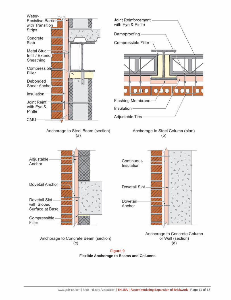
Connectors, anchors or ties that transfer load from the brick wythe to a structural frame or backing that provides lateral support should resist movement perpendicular to the plane of the wall (tension and compression) but allow movement parallel to the wall without becoming disengaged. This flexible anchorage permits differential movement between the structure and the brickwork. Figure 9 shows typical methods for anchoring masonry walls to columns and beams. Technical Note 44B provides detailed information about masonry ties and anchors.
The size and spacing of anchors and ties are based on tensile and compressive loads induced by lateral loads on the walls or on prescriptive anchor and tie spacing requirements in building codes. Technical Note 44B lists recommended tie spacing based on application.
There must be sufficient clearance among the masonry elements and the beams and columns of the structural frame to permit the expected differential movement. The masonry walls may be more rigid than the structural frame. This clearance provides isolation between the brickwork and frame, allowing independent movement.
COMBINING MATERIALSAs discussed in Technical Note 18, brick have different movement properties compared with other building materials. When other materials are used in combination with brick, the movement properties of that building material (concrete, concrete masonry cast stone, etc.) must be considered. To reduce the potential for cracking in a multi-wythe wall of brick and concrete masonry, movement joints must be installed in each wythe to accommodate the differential movement between the materials. In this case, expansion joints are placed in the brick wythe, and control joints are placed in the concrete masonry, although they do not necessarily have to be aligned through the wall. Another way to separate wythes or bands of materials that express different movement properties is to install a bond break to allow each material to move independently.
www.gobrick.com | Brick Industry Association | TN 18A | Accommodating Expansion of Brickwork | Page 11 of 13
Figure 9Flexible Anchorage to Beams and Columns
www.gobrick.com | Brick Industry Association | TN 18A | Accommodating Expansion of Brickwork | Page 12 of 13
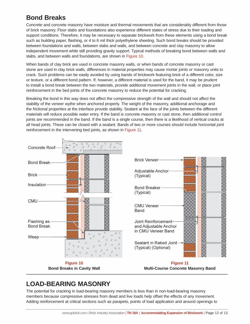
Bond BreaksConcrete and concrete masonry have moisture and thermal movements that are considerably different from those of brick masonry. Floor slabs and foundations also experience different states of stress due to their loading and support conditions. Therefore, it may be necessary to separate brickwork from these elements using a bond break such as building paper, flashing, or 4 to 6 mil thick polyethylene sheeting. Such bond breaks should be provided between foundations and walls, between slabs and walls, and between concrete and clay masonry to allow independent movement while still providing gravity support. Typical methods of breaking bond between walls and slabs, and between walls and foundations, are shown in Figure 10.
When bands of clay brick are used in concrete masonry walls, or when bands of concrete masonry or cast stone are used in clay brick walls, differences in material properties may cause mortar joints or masonry units to crack. Such problems can be easily avoided by using bands of brickwork featuring brick of a different color, size or texture, or a different bond pattern. If, however, a different material is used for the band, it may be prudent to install a bond break between the two materials, provide additional movement joints in the wall, or place joint reinforcement in the bed joints of the concrete masonry to reduce the potential for cracking.
Breaking the bond in this way does not affect the compressive strength of the wall and should not affect the stability of the veneer wythe when anchored properly. The weight of the masonry, additional anchorage and the frictional properties at the interface provide stability. Sealant at the face of the joints between the different materials will reduce possible water entry. If the band is concrete masonry or cast stone, then additional control joints are recommended in the band. If the band is a single course, then there is a likelihood of vertical cracks at all head joints. These can be closed with a sealant. Bands of two or more courses should include horizontal joint reinforcement in the intervening bed joints, as shown in Figure 11.
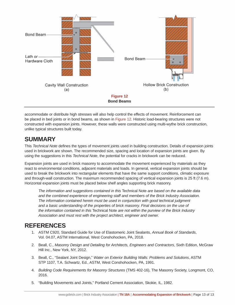
LOAD-BEARING MASONRYThe potential for cracking in load-bearing masonry members is less than in non-load-bearing masonry members because compressive stresses from dead and live loads help offset the effects of any movement. Adding reinforcement at critical sections such as parapets, points of load application and around openings to
Figure 11Multi-Course Concrete Masonry Band
Figure 10Bond Breaks in Cavity Wall
www.gobrick.com | Brick Industry Association | TN 18A | Accommodating Expansion of Brickwork | Page 13 of 13
accommodate or distribute high stresses will also help control the effects of movement. Reinforcement can be placed in bed joints or in bond beams, as shown in Figure 12. Historic load-bearing structures were not constructed with expansion joints. However, these walls were constructed using multi-wythe brick construction, unlike typical structures built today.
SUMMARYThis Technical Note defines the types of movement joints used in building construction. Details of expansion joints used in brickwork are shown. The recommended size, spacing and location of expansion joints are given. By using the suggestions in this Technical Note, the potential for cracks in brickwork can be reduced.
Expansion joints are used in brick masonry to accommodate the movement experienced by materials as they react to environmental conditions, adjacent materials and loads. In general, vertical expansion joints should be used to break the brickwork into rectangular elements that have the same support conditions, climatic exposure and through-wall construction. The maximum recommended spacing of vertical expansion joints is 25 ft (7.6 m). Horizontal expansion joints must be placed below shelf angles supporting brick masonry.
The information and suggestions contained in this Technical Note are based on the available data and the combined experience of engineering staff and members of the Brick Industry Association. The information contained herein must be used in conjunction with good technical judgment and a basic understanding of the properties of brick masonry. Final decisions on the use of the information contained in this Technical Note are not within the purview of the Brick Industry Association and must rest with the project architect, engineer and owner.
REFERENCES1. ASTM C920, Standard Guide for Use of Elastomeric Joint Sealants, Annual Book of Standards,
Vol. 04.07, ASTM International, West Conshohocken, PA, 2018.
2. Beall, C., Masonry Design and Detailing for Architects, Engineers and Contractors, Sixth Edition, McGraw Hill Inc., New York, NY, 2012.
3. Beall, C., “Sealant Joint Design,” Water on Exterior Building Walls: Problems and Solutions, ASTM STP 1107, T.A. Schwartz, Ed., ASTM, West Conshohocken, PA, 1991.
4. Building Code Requirements for Masonry Structures (TMS 402-16), The Masonry Society, Longmont, CO, 2016.
5. “Building Movements and Joints,” Portland Cement Association, Skokie, IL, 1982.