88
Model 12300 Digital Level Transmitter / Controller Instruction No EU 3500 E 04/2000 With HART ® Communication Protocol
| Date post: | 26-Oct-2015 |
| Category: |
Documents |
| Upload: | julio-cesar-hernandez-trujillo |
| View: | 218 times |
| Download: | 14 times |
Model 12300 Digital LevelTransmitter / Controller
Instruction
No EU 3500 E
04/2000
With HART ®
Communication Protocol
2Instruction No EU 3500 E 04/2000
12 300 Series Level Transmitter/ Controller
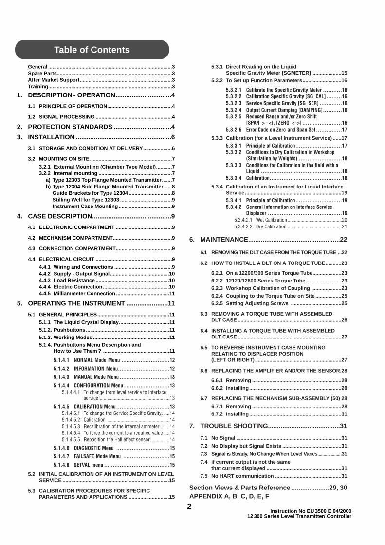
General ......................................................................................3Spare Parts................................................................................3After Market Support................................................................3Training......................................................................................3
1. DESCRIPTION - OPERATION...............................4
1.1 PRINCIPLE OF OPERATION.............................................4
1.2 SIGNAL PROCESSING .....................................................4
2. PROTECTION STANDARDS ................................4
3. INSTALLATION .....................................................6
3.1 STORAGE AND CONDITION AT DELIVERY....................6
3.2 MOUNTING ON SITE.........................................................7
3.2.1 External Mounting (Chamber Type Model)...........73.2.2 Internal mounting ...................................................7
a) Type 12303 Top Flange Mounted Transmitter.......7b) Type 12304 Side Flange Mounted Transmitter......8
Guide Brackets for Type 12304 ..............................8Stilling Well for Type 12303 ....................................9Instrument Case Mounting .....................................9
4. CASE DESCRIPTION............................................9
4.1 ELECTRONIC COMPARTMENT .......................................9
4.2 MECHANISM COMPARTMENT.........................................9
4.3 CONNECTION COMPARTMENT.......................................9
4.4 ELECTRICAL CIRCUIT .....................................................9
4.4.1 Wiring and Connections ........................................94.4.2 Supply - Output Signal .........................................104.4.3 Load Resistance ...................................................104.4.4 Electric Connection..............................................104.4.5 Milliammeter Connection .....................................11
5. OPERATING THE INSTRUMENT .......................11
5.1 GENERAL PRINCIPLES..................................................11
5.1.1 The Liquid Crystal Display...................................115.1.2. Pushbuttons..........................................................115.1.3. Working Modes .....................................................115.1.4. Pushbuttons Menu Description and
How to Use Them ? ..............................................11
5.1.4.1 NORMAL Mode Menu ............................12
5.1.4.2 INFORMATION Menu..............................12
5.1.4.3 MANUAL Mode Menu .............................13
5.1.4.4 CONFIGURATION Menu...........................135.1.4.4.1 To change from level service to interface
service.......................................................13
5.1.4.5 CALIBRATION Menu...............................135.1.4.5.1 To change the Service Specific Gravity......145.1.4.5.2 Calibration ................................................145.1.4.5.3 Recalibration of the internal ammeter .......145.1.4.5.4 To force the current to a required value.....145.1.4.5.5 Reposition the Hall effect sensor...............14
5.1.4.6 DIAGNOSTIC Menu ...............................15
5.1.4.7 FAILSAFE Mode Menu ...........................15
5.1.4.8 SETVAL menu ......................................15
5.2 INITIAL CALIBRATION OF AN INSTRUMENT ON LEVELSERVICE ..........................................................................15
5.3 CALIBRATION PROCEDURES FOR SPECIFICPARAMETERS AND APPLICATIONS.............................15
5.3.1 Direct Reading on the Liquid Specific Gravity Meter [SGMETER].....................15
5.3.2 To Set up Function Parameters...........................16
5.3.2.1 Calibrate the Specific Gravity Meter ...........165.3.2.2 Calibration Specific Gravity [SG CAL] .........165.3.2.3 Service Specific Gravity [SG SER] .............165.3.2.4 Output Current Damping [DAMPING]...........165.3.2.5 Reduced Range and /or Zero Shift
[SPAN > – <], [ZERO <–>] .......................165.3.2.6 Error Code on Zero and Span Set ...............17
5.3.3 Calibration (for a Level Instrument Service) ......175.3.3.1 Principle of Calibration...........................175.3.3.2 Conditions to Dry Calibration in Workshop
(Simulation by Weights) .........................185.3.3.3 Conditions for Calibration in the field with a
Liquid ...............................................185.3.3.4 Calibration..........................................18
5.3.4 Calibration of an Instrument for Liquid InterfaceService...................................................................195.3.4.1 Principle of Calibration...........................195.3.4.2 General Information on Interface Service
Displacer ...........................................195.3.4.2.1 Wet Calibration..........................................205.3.4.2.2. Dry Calibration ..........................................21
6. MAINTENANCE...................................................22
6.1 REMOVING THE DLT CASE FROM THE TORQUE TUBE ...22
6.2 HOW TO INSTALL A DLT ON A TORQUE TUBE...........23
6.2.1 On a 12200/300 Series Torque Tube....................236.2.2 12120/12800 Series Torque Tube.........................236.2.3 Workshop Calibration of Coupling .....................236.2.4 Coupling to the Torque Tube on Site ..................256.2.5 Setting Adjusting Screws ...................................25
6.3 REMOVING A TORQUE TUBE WITH ASSEMBLED DLT CASE ........................................................................26
6.4 INSTALLING A TORQUE TUBE WITH ASSEMBLED DLT CASE ........................................................................27
6.5 TO REVERSE INSTRUMENT CASE MOUNTING RELATING TO DISPLACER POSITION (LEFT OR RIGHT)............................................................27
6.6 REPLACING THE AMPLIFIER AND/OR THE SENSOR.28
6.6.1 Removing ..............................................................286.6.2 Installing................................................................28
6.7 REPLACING THE MECHANISM SUB-ASSEMBLY (50) 28
6.7.1 Removing ..............................................................286.7.2 Installing................................................................31
7. TROUBLE SHOOTING........................................31
7.1 No Signal .........................................................................31
7.2 No Display but Signal Exists .........................................31
7.3 Signal is Steady, No Change When Level Varies....................31
7.4 if current output is not the same that current displayed ....................................................31
7.5 No HART communication ..............................................31
Section Views & Parts Reference .....................29, 30APPENDIX A, B, C, D, E, F
Table of Contents
General
This manual provides installation, operation and mainte-nance instructions for the Masoneilan Model 12300 DigitalLevel Transmitter (DLT) with HART ® Communication proto-col. It also includes a complete parts reference and a list ofrecommended spare parts.
Spare Parts
When performing maintenance, use Masoneilan spareparts only. Parts can be obtained through your localMasoneilan Representative or the Spare Parts Department.When ordering parts, always include the Model and SerialNumber of the unit being repaired.
After Market Support
Masoneilan has a highly skilled After Sales Departmentavailable for start-up, maintenance, and repair of our valvesand instruments. Contact the nearest Masoneilan SalesOffice or Representative or After Sales Department.
Training
Regularly scheduled classes are conducted at theMasoneilan plant for training customer service and instru-mentation personnel in the operation, maintenance, andapplication of control valves and instruments.Arrangements for these services can be made through yourlocal Masoneilan Representative or the TrainingDepartment of Masoneilan.
3Instruction No EU 3500 E 04/200012 300 Series Level Transmitter/ Controller
Use of DANGER, WARNING, CAUTION, and NOTE.
These instructions contain DANGER, WARNING, CAUTION, and NOTE where necessary to alert youto safety related or other important information.
DANGER - Hazards which result in severe personal injury or death.WARNING - Hazards which could result in personal injury.CAUTION - Hazards which could result in equipment or property damage.NOTE - Alerts you to pertinent facts and conditions.
Although DANGER and WARNING hazards are related to personal injury, and the CAUTION hazardsinvolve equipment or property damage, it should be understood that operation of damaged equipmentcould, under certain operational conditions, result in degraded process system performance which maylead to personal injury or death. Therefore, comply fully with all DANGER, WARNING, and CAUTIONnotices.
IMPORTANT: SAFETY WARNING
Please read these instructions carefully BEFORE this instrument is installed or maintained. Products certified for use in explosionproof (flameproof) or intrinsically safe installations MUST
a) Be installed in accordance with local and national codes for hazardous area installations.
b) Only be used in situations which comply with the certification conditions stated in this handbook.
c) Only be maintained by qualified personnel with adequate training on hazardous area instrumentation.
Non-compliance with the rules and cautionary notes of this instruction may cause malfunction of the device orserious damage to it. In addition, such negligence may expose area personnel to severe hazards. Not intended foruse in life support systems.
Items sold by Masoneilan Dresser are warranted to be free from defects in materials and workmanship for a periodof one year from the date of manufacture, provided said items are used according to Masoneilan Dresser’s recom-mended usages.
Masoneilan Dresser reserves the right to discontinue manufacture of any product or change product materials,design, or specifications without notice.

4Instruction No EU 3500 E 04/2000
12 300 Series Level Transmitter/ Controller
The 12300 type Digital Level Transmitter/controller is ahigh performance, easy-to-set instrument based on amodular design that permits quick, low-cost upgrades asnew features are developed and as your needs change.
1.1 Principle of Operation
The Masoneilan 12300 series instrument is a 2-wire, looppowered, digital displacement level transmitter/controllerwith HART ® Communication that uses field provenbuoyancy and torque tube principles.
A change in liquid level varies the apparent weight of thedisplacer (130), which increases or decreases load on thetorque tube (136) by an amount directly proportional to thechange in liquid level.
The resulting rotation of the torque rod (138) modifies themagnetic field of a frictionless, non-contacting, Hall effect
sensor (141). The signal generated by the sensor variescurrent in the loop in proportion to the level in the vessel.
1.2 Signal Processing
The analog signal is converted into an error-free digitalsignal that can be processed by the on-board micro-controller. After the signal has been processed, the digitalresult is converted to a 4-20 mA analog output signal *.
- If the 12300 is configurated as transmitter, this 4-20mA analog output signal is the level measure.
- If the 12300 is configurated as controller, this 4-20 mAanalog output signal is not the level measure but theposition setpoint sent to the valve, so that the valvecontrols to achieve the required level setpoint. The12300 electronic turns then the signal of the Hall effectsensor into a different type of signal ( : valve position
Installation in a hazardous atmosphere must be performedin accordance with the requirements specified in the appli-cable standard for protection against explosion.
a) Transmitters Designed to be Installed in anIntrinsically Safe Circuit, according to EuropeanStandards EN 50014 and EN 50020 (CENELEC):
EEx ia IIC T6 (– 40 °C ≤ Ambient temperature ≤ 50 °C)
EEx ia IIC T5 (– 40 °C ≤ Ambient temperature ≤ 60 °C)
EEx ia IIC T4 (– 40 °C ≤ Ambient temperature ≤ 80 °C)
The main feature of this protection system is that nospark nor any thermal effect produced under the testsconditions required by the standard is capable ofcausing ignition of a given explosive atmosphere.
WARNING : Improper replacement or substitution ofelectronic components or of certain parts whosecharacteristics do not meet requirements of theapplicable standards for explosion protection mayvoid this protection.
Figure 1 — Diagram of Principle
Tothe amplifier
130 Displacer131 Displacer chamber135 Torque arm136 Torque tube
137 Torque tube housing138 Torque rod140 Magnets141 Hall effect sensor
* HART ® digital signal is superimposed to the 4-20 mA analog signal.
1. description-operation
2. protection standards
PARTS REFERENCES
setpoint) thanks to the control parameters stored.
Important:
- The controller option of the 12300 is available only ifthe customer has ordered a 12300 controller (seefig.2 - numbering system) he will then be able to confi-gure the 12300 wether as transmitter or as controller.
- If the customer has ordered a 12300 transmitter (seefig.2 - numbering system) he will then only be able toconfigure the 12300 as transmitter.
- The relevant controller information are discribed inannex F and in the HDLT communicator (joined).
The instrument is powered through the 2-wire series loop.
The instrument can be retrofitted to old style electronic orpneumatic heads to upgrade an instrument already inservice.
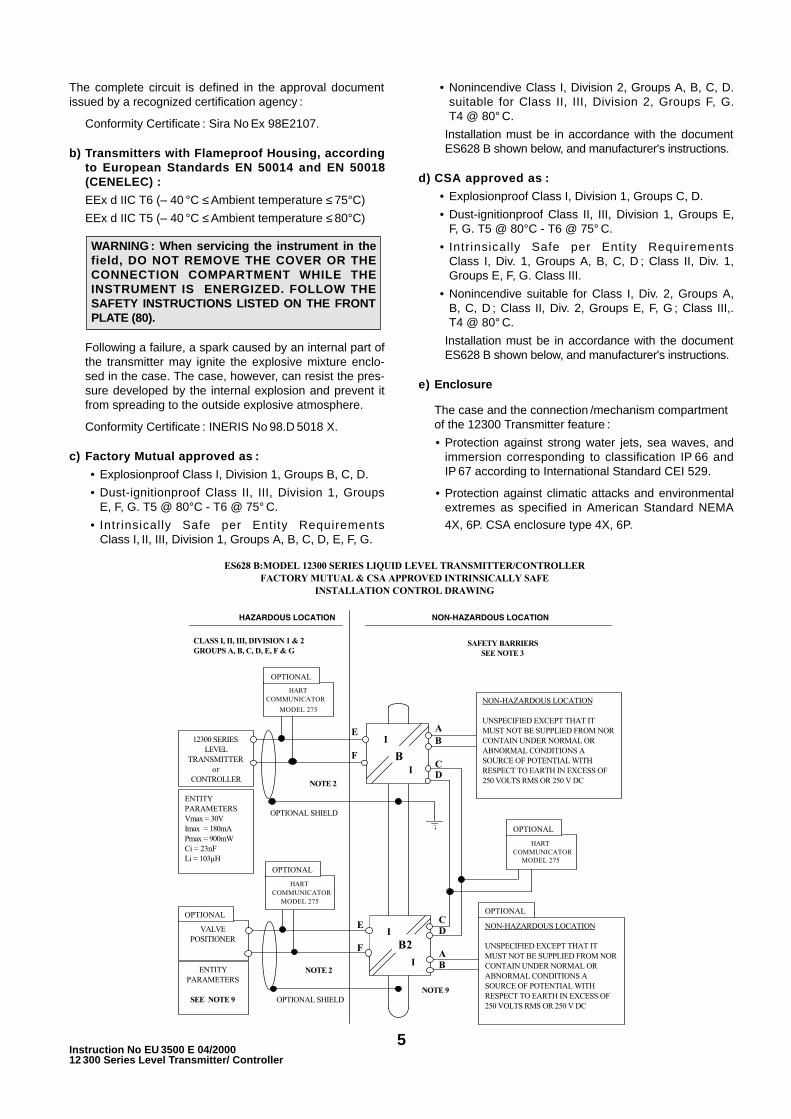
The complete circuit is defined in the approval documentissued by a recognized certification agency :
Conformity Certificate : Sira No Ex 98E2107.
b) Transmitters with Flameproof Housing, accordingto European Standards EN 50014 and EN 50018(CENELEC) :
EEx d IIC T6 (– 40 °C ≤ Ambient temperature ≤ 75°C)
EEx d IIC T5 (– 40 °C ≤ Ambient temperature ≤ 80°C)
Following a failure, a spark caused by an internal part ofthe transmitter may ignite the explosive mixture enclo-sed in the case. The case, however, can resist the pres-sure developed by the internal explosion and prevent itfrom spreading to the outside explosive atmosphere.
Conformity Certificate : INERIS No 98.D 5018 X.
c) Factory Mutual approved as :
• Explosionproof Class I, Division 1, Groups B, C, D.
• Dust-ignitionproof Class II, III, Division 1, GroupsE, F, G. T5 @ 80°C - T6 @ 75° C.
• Intrinsically Safe per Entity RequirementsClass I, II, III, Division 1, Groups A, B, C, D, E, F, G.
• Nonincendive Class I, Division 2, Groups A, B, C, D.suitable for Class II, III, Division 2, Groups F, G.T4 @ 80° C.
Installation must be in accordance with the documentES628 B shown below, and manufacturer's instructions.
d) CSA approved as :
• Explosionproof Class I, Division 1, Groups C, D.
• Dust-ignitionproof Class II, III, Division 1, Groups E,F, G. T5 @ 80°C - T6 @ 75° C.
• Intrinsically Safe per Entity RequirementsClass I, Div. 1, Groups A, B, C, D ; Class II, Div. 1,Groups E, F, G. Class III.
• Nonincendive suitable for Class I, Div. 2, Groups A,B, C, D ; Class II, Div. 2, Groups E, F, G ; Class III,.T4 @ 80° C.
Installation must be in accordance with the documentES628 B shown below, and manufacturer's instructions.
e) Enclosure
The case and the connection /mechanism compartmentof the 12300 Transmitter feature :
• Protection against strong water jets, sea waves, andimmersion corresponding to classification IP 66 andIP 67 according to International Standard CEI 529.
• Protection against climatic attacks and environmentalextremes as specified in American Standard NEMA4X, 6P. CSA enclosure type 4X, 6P.
WARNING : When servicing the instrument in thefield, DO NOT REMOVE THE COVER OR THECONNECTION COMPARTMENT WHILE THEINSTRUMENT IS ENERGIZED. FOLLOW THESAFETY INSTRUCTIONS LISTED ON THE FRONTPLATE (80).
5Instruction No EU 3500 E 04/200012 300 Series Level Transmitter/ Controller
6Instruction No EU 3500 E 04/2000
12 300 Series Level Transmitter/ Controller
3.1 STORAGE AND CONDITION ATDELIVERY
Level instruments have been carefully packed in ourpremises to prevent them from damage during handlingand transportation.
Units must be stored in an area where temperatures arebetween – 45° C (– 49° F) and + 93° C (+ 200 F).
Units are factory dry calibrated (simulation by weight) tothe service specific gravity specified by the customer.When service specific gravity has not been specified, unitsare factory dry calibrated to a specific gravity of 1.
Recalibration is recommended when the actual specificgravity differs from calibration specific gravity.
Recalibration is needed when verification of instrumentperformance is made with liquid in the displacer chamber.
3. installation
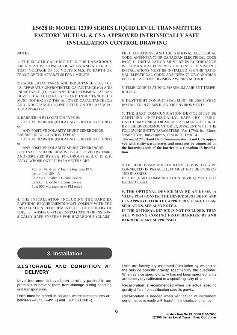
NOTES:
1. THE ELECTRICAL CIRCUIT IN THE HAZARDOUSAREA MUST BE CAPABLE OF WITHSTANDING AN A.C.TEST VOLTAGE OF 500 VOLTS R.M.S. TO EARTH ORFRAME OF THE APPARATUS FOR 1 MINUTE.
2. CABLE CAPACITANCE AND INDUCTANCE PLUS THEI.S. APPARATUS UNPROTECTED CAPACITANCE (Ci) ANDINDUCTANCE (Li) PLUS ANY HART COMMUNICATIONSDEVICE CAPACITANCE (Ci) AND INDUCTANCE (Li)MUST NOT EXCEED THE ALLOWED CAPACITANCE (Ca)AND INDUCTANCE (La) INDICATED ON THE ASSOCIA-TED APPARATUS.
3. BARRIER IN B1 LOCATION TYPE IS:- ACTIVE BARRIER (ISOLATING IS INTERFACE UNIT)
or- ANY POSITIVE POLARITY SHUNT ZENER DIODE.
BARRIER IN B2 LOCATION TYPE IS:- ACTIVE BARRIER (ISOLATING IS INTERFACE UNIT)
or- ANY POSITIVE POLARITY SHUNT ZENER DIODE.
BOTH SAFETY BARRIER MUST BE APPROVED BY FMRCAND CERTIFIED BY CSA FOR GROUPS A, B, C, D, E, F,AND G WHOSE OUTPUT PARAMETERS ARE:
Voc or Vt ≤ 30 V, but not less than 19 V.Isc or It ≤ 180 mACa ≥ Ci + C cable + C com. deviceLa ≥ Li + L cable + L com. devicePo ≤ 900 Mw (applies to FM only)
4. THE INSTALLATION INCLUDING THE BARRIEREARTHING REQUIREMENTS MUST COMPLY WITH THEINSTALLATION REQUIREMENTS OF THE COUNTRY OFUSE, I.E., ANSI/ISA RP12.6 (INSTALLATION OF INSTRIN-SICALLY SAFE SYSTEMS FOR HAZARDOUS (CLASSI-
FIED) LOCATIONS) AND THE NATIONAL ELECTRICALCODE, ANSI/NFPA 70 OR CANADIAN ELECTRICAL CODEPART 1. INSTALLATION MUST BE IN ACCORDANCEWITH MANUFACTURERS GUIDELINES. DIVISION 2INSTALLATIONS MUST BE INSTALLED PER THE NATIO-NAL ELECTRICAL CODE, ANSI/NFPA 70 OR CANADIANELECTRICAL CODE DIVISION 2 WIRING METHODS.
5. TEMP. CODE T4 AT 80°C. MAXIMUM AMBIENT TEMPE-RATURE.
6. DUST-TIGHT CONDUIT SEAL MUST BE USED WHENINSTALLED IN CLASS II, AND III ENVIRONMENTS.
7. THE HART COMMUNICATION DEVICE MUST BECERTIFIED INTRINSICALLY SAFE BY FMRC.HART COMMUNICATOR MODEL 275 MANUFACTUREDBY FISHER-ROSEMOUNT OR EQUIVALENT WITH THEFOLLOWING ENTITY PARAMETERS : Voc=1.7Vdc, Isc =32mA,Vmax=30Vdc, Imax=300mA, Ci=0.07µF, Li=0 T4.The model 275 Hand Held Communicator is not CSA appro-ved with entity parameteres and must not be connected onthe hazardous side of the barrier in a Canadian IS installa-tion.
8. THE HART COMMUNICATION DEVICE MUST ONLY BECONNECTED IN PARALLEL, IT MUST NOT BE CONNEC-TED IN SERIES.Isc + Isc (HART COMMUNICATION DEVICE) MUST NOTEXCEED 180mA.
9. THE OPTIONAL DEVICE MAY BE AN I/P OR AVALVE POSITIONNER. THE DEVICE MUST BE FM ANDCSA APPROVED FOR THE APPROPRIATE AREA CLAS-SIFICATION. SEE ALSO NOTE 2.IF THE OPTIONAL DEVICE IS NOT INCLUDED, THENALL WIRING COMING FROM BARRIER B1 ANDBARRIER B2 ARE SUPPRESSED.
ES628 B: MODEL 12300 SERIES LIQUID LEVEL TRANSMITTERSFACTORY MUTUAL & CSA APPROVED INTRINSICALLY SAFE
INSTALLATION CONTROL DRAWING
3.2 MOUNTING ON SITE
Unpack the unit carefully and record the serial number forfuture reference. Remove the shipping stud that securesthe displacer in the chamber.
Whenever possible, locate the transmitter at some easilyaccessible, well-lighted place on the vessel. The locationshould be such that the ambient temperature at the trans-mitter case is within the range of – 40 °C to +80 °C.
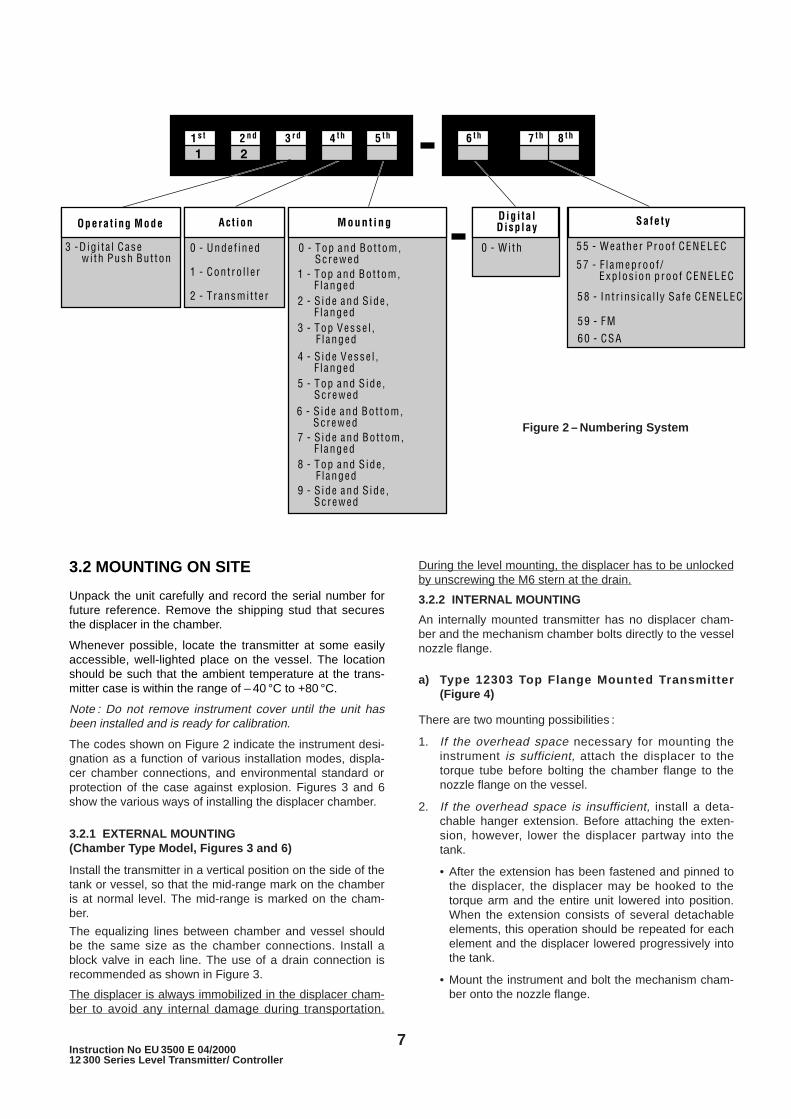
Note : Do not remove instrument cover until the unit hasbeen installed and is ready for calibration.
The codes shown on Figure 2 indicate the instrument desi-gnation as a function of various installation modes, displa-cer chamber connections, and environmental standard orprotection of the case against explosion. Figures 3 and 6show the various ways of installing the displacer chamber.
3.2.1 EXTERNAL MOUNTING(Chamber Type Model, Figures 3 and 6)
Install the transmitter in a vertical position on the side of thetank or vessel, so that the mid-range mark on the chamberis at normal level. The mid-range is marked on the cham-ber.
The equalizing lines between chamber and vessel shouldbe the same size as the chamber connections. Install ablock valve in each line. The use of a drain connection isrecommended as shown in Figure 3.
The displacer is always immobilized in the displacer cham-ber to avoid any internal damage during transportation.
During the level mounting, the displacer has to be unlockedby unscrewing the M6 stern at the drain.
3.2.2 INTERNAL MOUNTING
An internally mounted transmitter has no displacer cham-ber and the mechanism chamber bolts directly to the vesselnozzle flange.
a) Type 12303 Top Flange Mounted Transmitter(Figure 4)
There are two mounting possibilities :
1. If the overhead space necessary for mounting theinstrument is sufficient, attach the displacer to thetorque tube before bolting the chamber flange to thenozzle flange on the vessel.
2. If the overhead space is insufficient, install a deta-chable hanger extension. Before attaching the exten-sion, however, lower the displacer partway into thetank.
• After the extension has been fastened and pinned tothe displacer, the displacer may be hooked to thetorque arm and the entire unit lowered into position.When the extension consists of several detachableelements, this operation should be repeated for eachelement and the displacer lowered progressively intothe tank.
• Mount the instrument and bolt the mechanism cham-ber onto the nozzle flange.
7Instruction No EU 3500 E 04/200012 300 Series Level Transmitter/ Controller
Figure 2 – Numbering System

b) Type 12304 Side Flange Mounted Transmitter(Figure 5)
When the instrument is side flange mounted, enough clea-rance must be provided to permit attachment of the displa-cer after the chamber flange is bolted in place. To attachthe displacer, reach into the end of the protective case anddepress the torque arm. Then bring the displacer hangerup through the hole in the bottom of the case and slip thedisplacer hanger over the torque arm pin. Lower the displa-cer until the pin engages the top of the slot in the hanger.
Guide Brackets for Type 12304 (Figure 5)
If the liquid is in motion, provide brackets as shown inFigure 5 to guide the lower end of the displacer. Thediameter of the hole should be 25 to 35 mm (1” to 1 1/2”)larger than the diameter of the displacer for ranges to 1.8 m(6 feet), and 50 to 70 mm (2” to 3”) larger for greaterranges. The brackets should be placed at 50 to 70 mm (2”to 3”) from each end of the displacer. Locate the centerlineof the hole so that the displacer hangs freely.
8Instruction No EU 3500 E 04/2000
12 300 Series Level Transmitter/ Controller
Figure 3 — Typical Installation
Figure 4Type 12303
Figure 5 Type 12304
Figure 7Figure 6
Left Mounting(Top View)
Type 12300 (NPT Screwed)Type 12301 (Flanged)
Type 12305 (NPT Screwed)Type 12308 (Flanged)
Type 12306 (NPT Screwed)Type 12307 (Flanged)
Type 12309 (NPT Screwed)Type 12302 (Flanged)
Right Mounting(Top View)

Stilling Well for Type 12303 (Figure 4)
If the liquid is turbulent, provide a stilling well as shown inFigure 4.
The well should be made from tubing or pipe of a suitablediameter to allow sufficient clearance between displacerand pipe. It should be mounted so that it extends at least75 mm (3”) below a free hanging displacer.
A hole at the top of the stilling well should be provided toequalize pressure between well and vessel.
Instrument Case Mounting (Figure 7)
The standard case mounting is left hand — the case is tothe left of the displacer. Right hand mounting is optional. Toreverse instrument case mounting, refer to Section 6 —Maintenance.
9Instruction No EU 3500 E 04/200012 300 Series Level Transmitter/ Controller
The purpose of this section is to describe the various sub-assemblies of the instrument in order to facilitate their useand maintenance. (See Figures 19 to 21).
4.1 ELECTRONIC COMPARTMENT
The electronics compartment, located at the front of thetransmitter, can be accessed by removing the maincover (20). This cover contains a window (22) andthree push buttons (27).
The cover (20) is fully screwed on to the case (2), sealedwith an O-ring (109). It may be necessary to unscrew thecover by less than a turn to align the window and LCDdisplay and to install the safety screw (110).
The front plate (80), which is attached by three screws(125), protects the push buttons and provides a gasketseal (24).
The sensor (40) and its seal (111) are secured by twoscrews (112), located in the upper part of theelectronics compartment. The sensor is positioned sothat the blue mark is oriented toward the lower part ofthe case (see Figure 10). Another blue mark on thecase is a visual aid for the operator during reassembly.
The microprocessor, the display and the three pushbuttons are mounted on the potted electronic boardwhich makes the amplifier. This subassembly isinserted into the case with the display facing the top ofthe case. It is assembled by four screws (201).
For wiring, refer to Section 4.4.
4.2 MECHANISM COMPARTMENT
The mechanism compartment (Figures 20 & 21) on theback of the case has an opening on the right side(operator facing instrument) which is closed by athreaded cover (107) and a gasket (108). A secondopening at the bottom, closed by a special 3/4” NPT plug(190), allows access to the mechanical flexure (59),which is part of the beam.
The mechanism (50) [including parts (51 to 62)] iscompletely factory assembled and calibrated beforebeing installed into the mechanism compartment. Thepivot (51) is positioned toward the back of the casethrough two pins (52-53) and fastened by two screws(113). The beam (54) must be free to rotate withoutfriction (up to 7 degrees max.).
Two set screws (114) are located in tapped holes in theside of the case. The holes are covered by two plugs
(115). These set screws have no effect when mountingor dismounting the mechanism subassembly.
4.3 CONNECTION COMPARTMENT
The connection compartment is equipped with aterminal board (90). The flat handle terminal block,the test switch/pins, the HART ® connection pins andthe terminal board connector are mounted on theterminal board. The terminal board is mounted with 2screws (92).
The case is also equipped with radio frequency filterconnections between the terminal board connector andthe main electronic circuit.
To mount the safety screw (106), the cover must be fullyscrewed on the case and then unscrewed by less than aturn.
4.4 ELECTRIC CIRCUIT
4.4.1 WIRING AND CONNECTIONS
FLAT HANDLE TERMINAL BLOCK (90A)This item is located on the top side of the terminalboard in the connection compartment. Connect thepower supply leads to the terminal block. Pay attentionto polarity. Refer to Figures 19 and 20.
TERMINAL BOARD CONNECTOR (90B)This item is located on the bottom side of the terminalboard in the connection compartment. Ensure terminalboard connection with radio frequency filters. Payattention to polarity. Refer to Figure 20.
NOTE : This connection is made at the factory andmust not be adjusted or disconnected, except if theterminal board must be replaced.
SUPPLY TO MAIN BOARD (AMPLIFIER) (7)While facing the instrument this item is located on thebottom left side of the main board in the electronicscompartment. It connects the main board to the radiofrequency filters. Refer to Figures 19 and 21.
DANGER : Do not remove either compartmentcover in an explosionproof area when the instru-ment is powered. In an intrinsically safe installa-tion, follow code practice when servicing theinstrument in the field.
4. case description
10Instruction No EU 3500 E 04/2000
12 300 Series Level Transmitter/ Controller
NOTE : This connection is made at the factory andmust not be adjusted or disconnected, except if theamplifier must be replaced. Observe the connectingposition by means of the locking lugs, (below).
SENSOR CONNECTOR (40)
While facing the instrument this item is located on thetop bottom side of the main board in the electronicscompartment. It connects the sensor to the main board.Refer to Figures 19 and 21.
NOTE : This connection is made at the factory andmust not be adjusted or disconnected, except if theamplifier and/or sensor must be replaced. Observe theconnecting position by means of the locking lugs.
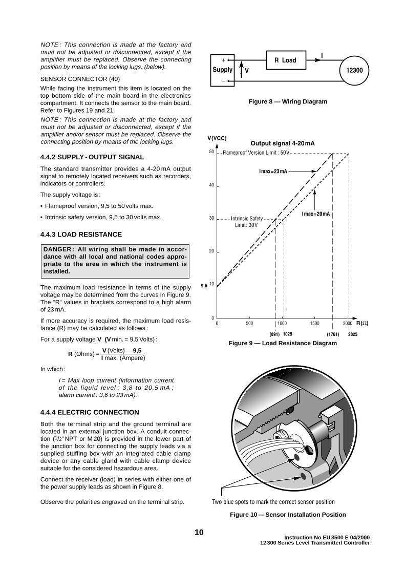
4.4.2 SUPPLY - OUTPUT SIGNAL
The standard transmitter provides a 4-20 mA outputsignal to remotely located receivers such as recorders,indicators or controllers.
The supply voltage is :
• Flameproof version, 9,5 to 50 volts max.
• Intrinsic safety version, 9,5 to 30 volts max.
4.4.3 LOAD RESISTANCE
The maximum load resistance in terms of the supplyvoltage may be determined from the curves in Figure 9.The “R” values in brackets correspond to a high alarmof 23 mA.
If more accuracy is required, the maximum load resis-tance (R) may be calculated as follows :
For a supply voltage V (V min. = 9,5 Volts) :
R (Ohms) = V (Volts) — 9,5I max. (Ampere)
In which :
I = Max loop current (information currentof the l iquid level : 3,8 to 20,5 mA ;alarm current : 3,6 to 23 mA).
4.4.4 ELECTRIC CONNECTION
Both the terminal strip and the ground terminal arelocated in an external junction box. A conduit connec-tion (1/2” NPT or M 20) is provided in the lower part ofthe junction box for connecting the supply leads via asupplied stuffing box with an integrated cable clampdevice or any cable gland with cable clamp devicesuitable for the considered hazardous area.
Connect the receiver (load) in series with either one ofthe power supply leads as shown in Figure 8.
Observe the polarities engraved on the terminal strip.
DANGER : All wiring shall be made in accor-dance with all local and national codes appro-priate to the area in which the instrument isinstalled.
Figure 10 — Sensor Installation Position
Two blue spots to mark the correct sensor position
Figure 8 — Wiring Diagram
Figure 9 — Load Resistance Diagram
11Instruction No EU 3500 E 04/200012 300 Series Level Transmitter/ Controller
4.4.5 MILLIAMMETER CONNECTION
An external milliammeter may be connected to thetransmitter to verify the signal without disconnectingthe power supply.
Remove the safety screw (106) and disassemble theconnection compartment cover (104). Put the switch on
the “TEST” position. Connect the milliammeter on thetwo pins located on each side of the switch. Beforedisconnecting the milliammeter put the switch back onthe position identified by “”. Fully screw the connec-tion compartment cover and unscrew it by less than 1turn to screw the safety screw. See Figure 19.
5. operating the instrument
5.1 General PrinciplesAll electronic calibrations of the DLT are made by means ofthree push buttons and a liquid crystal display on the frontof the instrument. The codes or values displayed by theLCD can be seen through a window. Access to the threepush buttons is obtained by removing the protective logoplate (80). It is not necessary to open the main cover forcalibration or adjustment of the instrument. Except formaintenance, the cover should remain closed.
5.1.1 The Liquid Crystal DisplayIt displays two lines and a bargraph. The upper linecan displays to five numerical digits and a decimal dot.The lower line can display alphanumeric digits.
On Normal operation, the LCD sequentially displaysthe loop current in mA and the level expressed in theunit displayed in the low left corner of the screen ; thelevel unit is generally % but an engineering unit canbe selected through [UNIT] in CALIBRATION menu.The bargraph length is proportional to the loopcurrent. The level value always increases with theheight of liquid in the tank or displacer chamberwhatever is the instrument action. For direct action,the current signal increases when level heightincreases ; for reverse action, the current decreaseswhen level increases.
The display is also used to Configure, Calibrate andDiagnose the DLT.
To facilitate these operations, values, codes or shortnames appear on the display. The various parametersare listed in the menus (see APPENDIX A, B, C, D, F).
5.1.2 Pushbuttons
Three pushbuttons (27) are located under the plate(80) on the front of the instrument. Remove the threescrews (125).
The left button is marked with a star , the middlebutton with the sign –, and the right one with the sign+.
means enter the function, accept or save to memory ;may be replaced by YES.
+ or – means : vertical movement in the programstructure ; may be replaced by NO or NEXT orPREVIOUS.
Note : 1. Do not overpush on the buttons. A buttonshould be depressed at least one second toperform the action.
2. Accidental pushing of the buttons will notcause any malfunction.
After using the buttons, reinstall the front plate (80) forNORMAL mode, which alternately displays the currentloop and the level of liquid.
5.1.3 Operating Modes
The instrument can operate under 3 modes :
• NORMAL Mode : it is the normal operating mode.The 4-20 mA output current is proportional to thelevel in the tank. The local digital display alternatelydisplays loop current and level expressed in theunit (% or engineering unit) shown in the low leftcorner of the screen. Reading of the instrumentdatabase is possible.
• MANUAL Mode : enter the manual mode wheninstrument configuration, calibration or diagnostic(set up or reading of diagnostic parameters) isrequired. The output current is not proportional tothe tank level in this mode.
• FAILSAFE Mode : the instrument automatically setsto the failsafe mode when an error or an alarm hasoccurred. The output current is set to the valueentered in the CONFIGURATION Menu.
5.1.4 Pushbuttons Menu DescriptionAnd How To Use Them ?
The menu structure for operating the 12300 from thelocal pushbuttons is shown on the next page. Sevenmenus are provided to configure, calibrate, diagnose orexit the failsafe mode ; an additional menu is providedto set numerical values of a selected parameter.
Five APPENDIX (A, B, C, D, F), display thecommunication paths within each menu, and providedescriptions and explanations of each screen.
• NORMAL Mode Menu (see APPENDIX A).
• INFORMATION Menu : (see APPENDIX A).
• MANUAL Mode Menu : (see APPENDIX A).

12Instruction No EU 3500 E 04/2000
12 300 Series Level Transmitter/ Controller
• CONFIGURATION Menu : (see APPENDIX B).
• CALIBRATION Menu : (see APPENDIX C).
• DIAGNOSTIC Menu : (see APPENDIX D).
• FAILSAFE Mode Menu : (see APPENDIX A).
• SETVAL menu : (see APPENDIX D).
• SPECIFIC menus : (see APPENDIX F).
Signs , + and – in the menus mean these buttonsshould be pressed to move into the menu.
means : enter the function, accept or save tomemory; may be replaced by YES.
+ or – means : vertical movement in the programstructure; may be replaced by NO or NEXT orPREVIOUS.
When screen [ – +/nn.nnn] is displayed, stroke + toincrease numerical value or – to decrease.
The various small screens in the menu diagramrepresent codes and/or numerical values displayed onthe LCD : explanations on the codes, on thecorresponding function and on the value limits aredescribed in the APPENDIXES.
A momentary (>1 s) press of a button either willchange menus or increase (or decrease) thedisplayed value by increments of 1 : see SETVALmenu.
5.1.4.1 NORMAL Mode Menu (APPENDIX A)This menu will allow you to :
• move to the MANUAL Mode Menu [–> MANU]where the instrument is in MANUAL Mode andcan be configured, calibrated or diagnosed,
• move to the INFORMATION Menu [–> INFO]where actual configuration, calibration anddiagnostics data can be READ ONLY. Note alsowhen you go to [–> INFO] the instrument is still inthe NORMAL Mode and still generates a 4 to 20mA signal proportional to the tank level,
• return to the NORMAL Mode.
Press any button to enter the NORMAL Mode Menufrom the normal operating mode.
5.1.4.2 INFORMATION Menu [–> INFO](APPENDIX A)When the instrument is in the NORMAL Mode thismenu will allow you to access databases to :
• Read configuration data : instrument function,direction of head mounting, action, failsafe option,high and low alarms, times before alarms flag areactivated, language.
• Read calibration data : damping coefficient, lowand high reference level current, low and highlevel, level unit, zero shift, reduced span,calibration specific gravity, service specific gravity,calibration specific gravity of specific gravitymeter.

13Instruction No EU 3500 E 04/200012 300 Series Level Transmitter/ Controller
• Read diagnostic data : accumulated tank filling,time at low or high level, total time of working,electronic board temperature.
• Read fault : displays all permanent faults whichmight have occurred since the last clear fault.
• Clear fault : displays the status of cleared faults.
NOTE : In the CONFIGURATION, CALIBRATIONDIAGNOSTIC AND FAILSAFE menus inAPPENDIX A to D, the screens which can bedisplayed to be READ ONLY under [–>INFO ] arenoted by .
To enter the INFORMATION Menu from theNORMAL Mode press in sequence : (or + or –), +,+, .
Then press the + or – button to move into theINFORMATION Menu and reach the desireddatabase to be read.
Press to enter the database. To display data,press + or –. To exit the database press .
To exit the INFORMATION Menu and return to theNORMAL Mode move to [<– NORM] using + or -and press .
5.1.4.2.1 To read the Calibration SpecificGravity [SG CAL] or the Service SpecificGravity [SG SER]
From the normal operating condition press , +,+, to move to the INFORMATION Menu, press ,+ to display [ CALIB ] then and + eight timesto display [SG CAL] (or [LSG CAL] and [HSGCAL] for an interface level). Press + one moretime to display the Service Specific Gravity [SGSER] or ([LSG SER] and [HSG SER] for aninterface level).
5.1.4.3 MANUAL Mode Menu [MANUAL](APPENDIX A)
The MANUAL Mode menu will allow you to move :
• to the CONFIGURATION Menu [–> CONFG]where configuration options are selected,
• to the CALIBRATION Menu [–> CALIB] where theinstrument is calibrated,
• to the DIAGNOSTIC Menu [–> DIAGN] wherediagnostic options are defined,
To enter the MANUAL Mode menu from the normaloperating mode press to enter the NORMALMode menu, + to reach [–> MANU] , to enter theMANUAL Mode then press any button to enter theMANUAL Mode menu,
To exit the MANUAL Mode menu move to[<– NORM ] and press . [NORMAL] appears for afew seconds and the instrument automaticallyreturns to the NORMAL Mode display.
5.1.4.4 CONFIGURATION Menu [CONFIG](APPENDIX B)
This menu allows you to set the followingconfiguration options :
• the instrument function (level or interface),
• the direction of head mounting (left or rightdisplacer when facing the LCD window),
• the action (direct:current increases with level;reverse: current decreases when level increases),
• the FAILSAFE current,
• the high and low alarms,
• the time delay prior to triggering off an alarm,
• the time duration before the instrument goes intothe Failsafe mode,
• the language of the display.
To enter the CONFIGURATION Menu : enter theMANUAL Mode menu and move into the menu to[–> CONFG], press to display [CONFIG] thenpress any button to enter the menu.
To exit the CONFIGURATION Menu and return tothe NORMAL Mode display, move into the menuuntil [< MANU] is displayed and press to display[STORAGE]. Press any button then (to save data)or + or – (no to save data) to display [MANUAL].
Then press , –, : the instrument automaticallyreturns to the NORMAL Mode display after[NORMAL] has been displayed for a few seconds.
5.1.4.4.1 To change the configuration fromlevel service to interface level service
• From the normal operating condition press , +,, to display [MANUAL],
• Press any button then to display [CONFIG],
• Press any button to display [LEVEL],
• Press to display [INTERF]. The instrument isnow configured as an interface level transmitter,
• To return to the NORMAL Mode and save thenew configuration move into the menu using +or – to display [<– MANU],
• Press , , , –, –, to return to the NORMALMode.
5.1.4.5 CALIBRATION Menu [CALIBR](Appendix C)This menu allows you to:
• perform instrument coupling to the torque tube,
• perform the instrument calibration (transmitter andspecific gravity meter),
• change the calibration and service specific gravity,
• adjust the damping coefficient applied to the loopcurrent,
INFO
14Instruction No EU 3500 E 04/2000
12 300 Series Level Transmitter/ Controller
• set the current corresponding to the low and highlevels,
• select the display unit,
• adjust the low and high loop current,
• adjust zero and span for the reduced scale,
• recalibrate the internal milliammeter and/or force agiven loop current.
To enter the CALIBRATION Menu from theNORMAL Mode, press , + , , to enter theMANUAL Mode menu and move in the menu to[–> CALIB]. Press to display [CALIBR] then pressany button to enter the menu.
To exit the CALIBRATION Menu and return to theNORMAL Mode display, move into the menu until[<-MANU] is displayed and press to display[MANUAL].
Then press , –, : the instrument automaticallyreturns to the NORMAL Mode display after[NORMAL] has been displayed for a few seconds.
5.1.4.5.1 To Change the Service SpecificGravity, [To avoid re-calibration if servicespecific gravity (ies) is (are) different fromcalibration specific gravity (ies)]
From the NORMAL Operating condition press ,+, , to display [MANUAL].
• Press any button to enter the MANUAL Modemenu.
• Press + to display [–> CALIB] then to display[CALIBR].
• Press +, + to display [CHG SG].
• Press to display the specific gravity.
a) For a “level” instrument,
• Enter the Specific Gravity of Service [SGSER] .
b) For an “interface” instrument,
• Enter the Low and High Specific Gravities ofService [LSG SER] and [HSG SER].
• Press to enter SETVAL menu. See SETVALmenu (Section 5.1.4.8) to change the servicespecific gravity.
• After adjustment press to exit SETVAL menu.
• Press + or – to display [<– ].
• Press to display [STORAGE]. Press anybutton then to save new specific gravity. andto display [CHG SG].
• To return to the NORMAL Mode move into themenu using + or –. to display [<– MANU].
• Press , , –, to return to the NORMALMode.
5.1.4.5.2 Calibration
To calibrate the instrument :
a) For a “level” instrument,
• Set the Specific Gravity value of the liquid usedfor calibration [SG CAL] and take the REF L[ZERO] and REF H [SPAN],
b) For an “interface” instrument,
• Set the Low and High Specific Gravities of theliquids used for calibration and take the REF L[ZERO] and REF H [SPAN],
c) For a “level” or an “interface” instrument,
• Set the currents and levels corresponding toREF L and REF H,
• Define the unit for level indication,
• Set the Zero and Span for reduced scale (Referto Section 5.3.2.5),
• Set the damping action applied to the loopcurrent (Refer to Section 5.3.2.4),
• Calibrate the specific gravity meter, (Refer toSection 5.3.2.1),
To enter the CALIBRATION Menu from theNormal operating mode, press in sequence :
(or + or –), +, , , +, , to display [CALIBR].
To quit the CALIBRATION Menu and return toNormal Operating mode, move into the menuuntil [<-MANU] is displayed, then press todisplay [MANUAL], via [STORAGE] and[YES NO].
Then press , –, : [NORMAL] appears for a fewseconds and the instrument automatically returnsto Normal Operating displaying alternatively thecurrent and the level.
5.1.4.5.3 Recalibration of the internal ammeter
CAUTION : Must be done only if currentoutput is not the same as the currentdisplayed.
Move to sub-menu [4 20 MA]. (Refer toSection 7 – Trouble Shooting and APPENDIX C).
5.1.4.5.4 Force the current to display arequired value
Allows setting another instrument (such as apositioner) in series in the loop, generating arequired output current. Move to sub-menu[4 20 MA] then [MA GENE] and proceed as indi-cated in APPENDIX C).
5.1.4.5.5 Reposition the Hall effect sensortowards the torque tube rod
Only necessary after installation of aninstrument on the torque tube. Move to sub-menu [COUPLNG]. (Refer to Sections 6.2.3 or6.2.4).

15Instruction No EU 3500 E 04/200012 300 Series Level Transmitter/ Controller
5.1.4.6 DIAGNOSTIC Menu [DIAGNOS](Appendix D)
This menu allows you to:
• Get information on working data : accumulatedtank filling, time during which the level was high orlow, total time of working, board temperature,
• Test the Hall effect sensor,
• Tune manually or automatically the smart filteringfunction,
• Test the specific gravity meter,
• Get the history of faults (permanent and nonpermanent),
• Reset the diagnostics database,
To enter the DIAGNOSTIC Menu from the NORMALMode press , +, to enter the MANUAL Modemenu and move in the menu to [–> DIAGN]. Press to display [DIAGNOS] then press any button toenter the menu.
To exit the DIAGNOSTIC Menu and return to theNORMAL Mode display, move into the menu until[<– MANU] is displayed :and press to display[MANUAL].
Then press , –, : the instrument automaticallyreturns to the NORMAL Mode display after[NORMAL] has been displayed for a few seconds.
5.1.4.7 FAILSAFE Mode menu (Appendix A)
The FAILSAFE mode menu allows you to :
• Read fault which has occurred,
• Clear fault which has occurred,
• Reset to factory default settings,
• Return to NORMAL Mode.
When the instrument is in the FAILSAFE Mode itdisplays [FAILSAF]. To enter the FAILSAFE Modemenu press any button.
To exit move in the menu to [–> NORM] andpress . The instrument automatically returns to theNORMAL Mode display after [REV xxx] and[NORMAL] have been displayed for a few seconds.
5.1.4.8 SETVAL menu (Appendix D)
This setting values menu is used to set numericalvalues for any function requiring such an action. Toenter or exit SETVAL menu from a function press .
When entering SETVAL menu [<–#.###] is displayed.
Push + to display [ ^#.###], then + or – to shift the
sign ^ below the number to be changed.
Push to display [–#.###+]. Push + to increase or – todecrease to change the number.
Validate by . Repeat for each digit.
To exit the SETVAL menu press + or – to display[<–#.###]. Then press .
5.2 Init ial Calibration of anInstrument on Level ServiceTo perform a first calibration and running in case of a levelapplication of the instrument refer to APPENDIX E.
5.3 Calibration Procedures forSpecif ic Parameters andApplications
After the 12300 Level Instrument has been installedand connected, remove the front plate (80) located infront of the instrument to gain access to the pushbuttons and select all required configuration data asindicated in the Section 5.1.4.4. APPENDIX B, thenproceed as follows:
NOTE : The electronic circuit has been factoryadjusted during instrument manufacturing to 4-20 mA,using a reference milliammeter.
So, for calibration on site, no measurement instrumentis required.
However, if the loop current must be verified and if fullcompliance with standards requirements forinstruments installed in hazardous areas is required,insert the milliammeter in series with the power supplyor connect it to the electronic board provided into theconnection compartment. Put the switch on the“TEST” position. Connect the milliammeter on the twopins located on each side of the switch. Beforedisconnecting the milliammeter put the switch back onthe position identified by “”. See Figure 19.
5.3.1 Direct Reading on the LiquidSpecific Gravity Meter [SGMETER]
• If displacer volume is lower than 1270 cm3 andservice specific gravity X displacer volume islower than 1270.
• If the displacer is fully immersed in the liquidand if the [SGMETER] function has beenpreliminary calibrated.
To calibrate the [SGMETER] function, refer toSection 5.3.2.1.
To read specific gravity of the process liquid :
• Fill the displacer chamber until the displacer is fullyimmersed in the process liquid.
• Move into the DIAGNOSTIC Menu (APPENDIX D)until [RD CTR] then [SGMETER] are displayed. Push to read the value. Return to normal operation.
Danger : If area cannot be verified as safe, donot remove any covers.
Caution : Direct reading of specific gravity iscorrect only :

16Instruction No EU 3500 E 04/2000
12 300 Series Level Transmitter/ Controller
5.3.2 To Set up Parameters
5.3.2.1 Calibrate the Specific Gravity MeterThis adjustment is made at the factory for completeinstruments. Use of the specific gravity function[SGMETER] aids in performing on site newcalibrations of simulations with or without liquid.
Caution : The Specific Gravity Meter function isfactory calibrated at a specific gravity of 1 forcomplete instrument only if the displacervolume is lower than 1270 cm 3 and the weight is1362 g.For an instrument delivered alone with a torquetube, the Specific Gravity Meter function isfactory calibrated at a SG 1 for a displacer with907 cm3 / 1362 g.If actual displacer characteristics differs fromthese values, recalibration is necessary and willbe possible only if displacer volume is lower than1270 cm3 and service specific gravity x displacervolume is lower than 1270 :
Proceed as follows :
a. Move to CALIBRATION Menu (APPENDIX C)until [SGM CAL], then [SG CAL] are displayed.Validate by to enter SETVAL menu and set thespecific gravity of 1. Store data.
b. Empty the chamber or simulate the low level byusing weights and stabilize the displacer (or theweights).
c. Display [ZERO ] and press to set the REF L.
NOTE : During the procedure, refer to Section5.3.2.6 if the LCD displays [ERROR].
d. Attach a set of weights to the torque arm tosimulate a high level or fill the displacer chamberuntil the high level is reached. Stabilize thedisplacer (or the weight).
• On site : Fill the displacer chamber until highlevel (REF H) is reached by a specific gravity1 liquid.
• In workshop : Simulate by weights the highlevel (REF H) corresponding to the apparentweight of the actual displacer fully immersedin a specific gravity 1 liquid.
e. Display [SPAN ] and press to set the REF H,
f. Move until [<– ] is displayed and press tostore data via [STORAGE] and [YES NO]screens. [CAL Z S] is displayed,
g. Exit the CALIBRATION Menu via [<–MANU] and then move into the DIAGNOSTIC menu(APPENDIX D) until [RD CTR] then [SGMETER]are displayed. Push to read the value andcheck if the calibration is successful. Return toNORMAL Operation Mode.
5.3.2.2 Calibration Specific Gravity [SG CAL]The calibration specific gravity is that of the liquid used(or simulated by weights) for calibration of zero andspan in the CALIBRATION Menu.
It should be modified only if zero and span calibrationare performed again for a liquid of different specificgravity. Refer to Section 5.3.3.4—Calibration, Steps 1to 7.
5.3.2.3 Service Specific Gravity [SG SER]
The service specific gravity is the one used for thefunction [SG SER] in the CALIBRATION Menu.
Its value is identical to that of [SG CAL] just aftercalibration. If the specific gravity of the processliquid is different, modify the value of [SG SER].
Two cases are possible :
a) If the specific gravity of the liquid is unknown ,you must first measure specific gravity of the liquidby using the function [SGMETER]. See Section5.3.1, then proceed as follows :
b) If the specific gravity is known, it can bemodified, regardless of what the liquid level in thedisplacer chamber is. To adjust the value :
Move into the CALIBRATION Menu until [CALIBR],[CHG SG] then [SG SER] are displayed.
Validate by to enter SETVAL menu and set thespecific gravity. Return to normal operation.
5.3.2.4 Output Current Damping [DAMPING]
In case of rapid oscillations of the level or if theliquid is in motion, it may be necessary to filter theoutput signal. A first order digital filter is provided foradjusting the damping coefficient.
Enter the CALIBRATION Menu, move to display[VAR SET], then [DAMPING] and validate by toenter SETVAL menu and set the filtering coefficient.Return to normal operation.
5.3.2.5 Reduced Range and /or Zero Shift[SPAN > – <], [ZERO <–>]
For an application where the level change is smallerthan the displacer height, it is possible to obtain thefull signal range for this reduced level range.
• Enter the CALIBRATION Menu, move to display[VAR SET], then [ZERO <–>] and validate by toenter SETVAL menu and set the zero shift value.Return to the [ZERO <–>] screen by ,
• Move to display [SPAN > – <] and validate by toenter SETVAL menu and set the span reductionvalue. Return to display [SPAN > – <] screen by ,
• Move until [<– ] is displayed and press to storedata via [STORAGE] and [YES NO] screens.[VAR SET] is displayed,
Caution : In interface service , if the [LSG SER]and/or [HSG SER] are modified, an automaticcalculation is performed to set a new value in[ZERO <–>].

17Instruction No EU 3500 E 04/200012 300 Series Level Transmitter/ Controller
• Exit the CALIBRATION Menu via [<–MANU] and then return to NORMAL Operation Mode via theMANUAL Mode.
Example : To modify a calibration so that 0 %corresponds to a displacer immersed to 1/4 of itsheight (25 %), and 100 % corresponds to a displa-cer immersed to 4/5 of its height (80 %), adjustzero shift to 25 % and span reduction to 45 %,(see schematic on Figure 11).
5.3.2.6 Error Code on Zero and Span Set
a) The value of the span can be accepted before orafter the zero value is entered. If you accept thezero without simulating the corresponding levelchange, the LCD displays [ERROR]. Press todelete the message and then perform (or simu-late) the level change before acquiring the newvalue.
b) The LCD may also display [ERROR] for a newcalibration if :
• The zero value is higher or equal to the span ofthe preceding calibration. If so, accept andstore the span first and then the zero.
• The span value of the new calibration is smal-ler than the zero value of the preceding calibra-tion. If so, accept and store the zero value firstand then the span.
5.3.3 Calibration (for Level InstrumentService)
5.3.3.1 Principle of CalibrationThe electronic circuit is calibrated towards tworeference levels (REF L and REF H), see Schematicbelow :
• REF L corresponds to the displacer completely out ofliquid.
• REF H corresponds to the displacer fully immersedin the liquid of Specific Gravity used for calibration[SG CAL].
The loop current corresponding to REF L may be setthrough [MA L] via [VAR SET] ; it is generally 4 mA.
The current corresponding to REF H may be setthrough [MA H] via [VAR SET] ; it is generally 20 mA.
Caution : If new calibration is performed, theparameters of the reduced range [SPAN > – <]and/or zero shift function [ZERO <–>] areautomatically set to zero.In interface service : If the [LSG SER] and/or[HSG SER] are modified, an automatic calcula-tion is performed to set a new value in[ZERO <–>].
Figure 11Schematic Example of Reduced Range

18Instruction No EU 3500 E 04/2000
12 300 Series Level Transmitter/ Controller
The value of [MA H] shall always be higher than thevalue of [MA L].
The level indication corresponding to REF L is setthrough function [LEVEL L] via [VAR SET] ; it isexpressed in the unit set through [UNIT] function ; ifUNIT is “%”, LEVEL L should be 0.0.
The level indication corresponding to REF H is setthrough function [LEVEL H] via [VAR SET] ; it isexpressed in the unit set through [UNIT] function ; ifUNIT is “%”, LEVEL H should be 100.0.
The electronic circuit is calibrated so that the indicatorrange 4-20 mA corresponds to the indication of amilliammeter inserted in series with the supply circuitof the DLT. Therefore it is not necessary to connect amilliammeter when performing an on site calibration ;the instrument display is sufficient.
5.3.3.2 Conditions for Dry Calibration inWorkshop (Simulation by Weights)
Parameter Name S.I Units English UnitsDisplacer Weight g lbmDisplacer Volume cm3 in3
Water Density (WD) 1 g/cm3 0.036 lbm/in3
The effective change in level will be simulated by aset of weights corresponding to :
a) The weight of the actual displacer at low level(REF L), which allows you to calibrate the zeroand obtain the minimum value [ 0,0%] of thesignal (direct action).
b) The apparent displacer weight when the levelis high (REF H). This allows you to calibrate thespan and obtain the maximum value [100,0%] ofthe signal (direct action). The correspondingweight is calculated as :
Proceed as indicated under 5.3.3.4 Calibration :
5.3.3.3 Conditions for Calibration in the fieldwith a Liquid
The effective change in level will be obtained byemptying and filling of the displacer chamber with aliquid.
Wait for the displacer to stabilize to validate thevalues displayed after each change in liquid level.
Take actions necessary to allow a change in theliquid level in the chamber : open/close isolationvalves, vent, purge, etc.
Proceed as indicated under 5.3.3.4 Calibration :
5.3.3.4 Calibration
1. Switch on the power. Attach a set of weights tothe torque arm to simulate a low level or emptythe displacer chamber.
2. Enter the CALIBRATION Menu and press insequence : (or + or –), +, , , +, , to display[CALIBR],
3. Set the Specific Gravity value of the liquid usedfor calibration [SG CAL]. Refer to Section 5.1.4.8for the SETVAL sub-menu,
4. Display [ZERO ] and press to set the REF L,
NOTE : During the procedure, refer to Section5.3.2.6 if the LCD displays [ERROR].
5. Attach a set of weights to the torque arm tosimulate a high level or fill the displacer chamberuntil the high level is reached,
6. Display [SPAN ] and press to set the REF H,
7. Move until [<– ] is displayed and press tostore data via [STORAGE] and [YES NO]screens. [CAL Z S] is displayed,
8. Move to [VAR SET] to display successively[MA L], [MA H], [LEVEL L], [LEVEL H] and, ifneeded, set the currents and levels correspon-ding to REF L and REF H,
9. Display [UNIT ] and define the unit for level indi-cation,
10. If necessary, display [DAMPING] and set thedamping action applied to the loop current. (Ref.to Section 5.3.2.4),
11. If necessary, set zero and span for reducedrange. (Ref. to Section 5.3.2.5),
12. Move until [<– ] is displayed and press tostore data via [STORAGE] and [YES NO]screens. [VAR SET] is displayed,
13. When the calibration is completed, move into themenu until [<–MANU] is displayed, then press to exit the CALIBRATION Menu and to display[MANUAL],
14. Press , –, : [NORMAL] appears for a fewseconds and the instrument automaticallyreturns to Normal Operating display,
15. Reinstall the front plate (80) with the threescrews (125).
Apparent Displacer Weight =Displacer Actual Weight – (Displacer Actual Volume x S.G.x WD)
Danger : Connection of a milliammeter in seriesmust be compatible with applicable hazardousarea standards requirements. Refer to Section4.4.4.
Caution : When performing a calibration, use thefollowing parameter units wherever they apply :
Caution : Actual volume and weight of the displa-cer can be read using HART ® protocol only ifthey have been previously stored in the DLT head.Otherwise, actual volume of the displacer ismarked on the specification plate (124).
Weigh the displacer to get the actual weight.

19Instruction No EU 3500 E 04/200012 300 Series Level Transmitter/ Controller
NOTE : The calibration specific gravity [SGCAL] is automatically stored in the service speci-fic gravity function [SG SER]. If the instrument isto be used with a liquid of different specificgravity, reenter the CALIBRATION Menu to setand accept this new value in [SG SER]. (SeeSection 5.3.2.3).
5.3.4 Calibration of an Instrument forLiquid Interface Service5.3.4.1 Principle of CalibrationThe level transmitter is used to measure the interfacelevel of two immiscible liquids of different specificgravit ies. The displacer must always be fullyimmersed.
The electronic circuit is calibrated towards tworeference levels (REF L and REF H) :
• REF L corresponds to the displacer completely out ofliquid.
• REF H corresponds to the displacer fully immersedin the liquid of Specific Gravity used for calibration[SG CAL].
The loop current corresponding to REF L may be setthrough [MA L] via [VAR SET] ; it is generally 4 mA.
The current corresponding to REF H may be setthrough [MA H] via [VAR SET] ; it is generally 20 mA.
The value of [MA H] shall always be higher than thevalue of [MA L].
The level indication corresponding to REF L is setthrough function [LEVEL L] via [VAR SET] ; it isexpressed in the unit set through [UNIT] function ; ifUNIT is “%”, LEVEL L should be 0.0.
The level indication corresponding to REF H is setthrough function [LEVEL H] via [VAR SET] ; it isexpressed in the unit set through [UNIT] function ; ifUNIT is “%”, LEVEL H should be 100.0.
The electronic circuit is calibrated so that the indicatorrange 4-20 mA corresponds to the indication of amilliammeter inserted in series with the supply circuitof the DLT.
Therefore it is not necessary to connect amilliammeter when performing an on site calibration ;the instrument display is sufficient.
5.3.4.2. General Information on interfaceservice displacers
Under this Section we will consider a standarddisplacer any displacer with the followingcharacteristics :
• Volume V : ≤ 1270 cm3 (≤ 77 in3), marked onspecification plate (124),
• Product of V x SG ≤ 1270,• Weight = 1362 g (3 lbm).
A standard displacer may be used when the liquidspecific gravity difference is between 0.1 and 1.4 (withlower accuracy between 0.1 to 0.2). The lowest specificgravity (d1) liquid is 1.3 max. The highest specific gravity(d2) liquid is between 0.1 and 1.4.
Danger : Connection of a milliammeter in seriesmust be compatible with applicable hazardous areastandards and requirements. Refer to Section 4.4.4.
Caution : Special displacers may be provided forspecific applications (material, service condi-tions…). In these cases, volume and/or weight willdiffer from standard displacer characteris tics.
Actual volume and weight of the displacer canbe read using HART ® protocol only if they havebeen previously stored in the DLT head.Otherwise, actual volume of the displacer ismarked on the specification plate (124).
20Instruction No EU 3500 E 04/2000
12 300 Series Level Transmitter/ Controller
NOTE : During following procedures, refer to Section5.3.2.6 if the LCD displays [ERROR].
5.3.4.2.1 Wet Calibration
The effective change in level will be obtained byemptying and filling of the displacer chamberwith the two liquids .
Wait for the displacer to stabilize to validate thevalues displayed after each change in interfaceof liquids.
Take actions necessary to allow a change in theinterface of liquids in the chamber : open/closeisolation valves, vent, purge, etc.
The procedure is identical to the one used forcalibrating a level transmitter in a liquid on site(see Section 5.3.3.4), except for the differencesoutlined below.
a. With the Process Liquids
1. Enter the specific gravities to be used for cali-bration by using the functions [LSG CAL]and [HSG CAL].
2. Take necessary action to allow change in liquidinterface level in the displacer chamber suchas isolating, vent, purge valves etc....It is thennecessary to put liquids in the chamber to:
3. Set the [ZERO]when the displacer is fully immer-sed in the lowest specific gravity liquid (d1).
4. Set the [SPAN] when the displacer is fully immer-sed in the highest specific gravity liquid (d2).
5. Complete the calibration as indicated inSteps 7 to 15 of the Section 5.3.3.4.
b. With the Highest Specific Gravity Liquid (d 2)
1. Take necessary action to allow change inliquid interface level in the displacer chambersuch as isolating, vent, purge valves etc....and then :
2. Enter the CALIBRATION Menu.
3. Enter the specific gravities to be used for cali-bration by using the functions [LSG CAL]and [HSG CAL].
4. Admit liquid (d2) into the chamber to fullyimmerse the displacer.
5. Set and store [SPAN] for interface configura-tion.
6. Quit CALIBRATION Menu.
7. In the DIAGNOSTIC Menu, move to [SGME-TER]. The specific gravity displayed mustcorrespond to the specific gravity of the liquidin the chamber. This assumes the [SGME-TER] has been calibrated.
8. Slowly empty the chamber until the LCDdisplays the lowest S.G. value (d1) andrecord this value.
9. Quit the [SGMETER] function and theDIAGNOSTIC Menu.
10. Return to CALIBRATION Menu.
11. Set the [ZERO] for interface configuration.
12. Complete the calibration as indicated inSteps 7 to 15 of the Section 5.3.3.4.
c. On Site Using Water if the Highest SpecificGravity (d 2) is ≤ 1
1. Take necessary action to allow change inliquid interface level in the displacer chambersuch as isolating, vent, purge valves etc....and then empty the chamber.
2. Enter the DIAGNOSTIC Menu and move to[SGMETER].
3. Increase the water level in the displacerchamber until LCD displays the value of theprocess lowest specific gravity (d1).
4. Quit [SGMETER] and enter the CALIBRA-TION Menu. Move until [CAL Z S], then [LSGCAL] and [HSG CAL] is displayed to enter(d1) and (d2).
5. Set and store [ZERO] for this water level (d1).
6. Quit the CALIBRATION Menu and return to[SGMETER] in the DIAGNOSTIC Menu.
7. Increase the water level in the displacerchamber until the LCD displays the value ofthe highest specific gravity (d2).
8. Quit [SGMETER] and the DIAGNOSTICMenu, then return to CALIBRATION Menu.
9. Set and store the [SPAN] for this new waterlevel (d2).
10. Complete the calibration as indicated inSteps 7 to 15 of the Section 5.3.3.4.
Weight of the displacer is only necessary on drycalibration to simulate the apparent weight ofthe displacer immersed into the liquids : Weighthe displacer to get the actual weight.
Caution : This procedure is only possible ifthe [SGMETER] function has been calibra-ted. Refer to Section 5.3.1.
Caution : This procedure is only possible ifthe [SGMETER] function has been calibra-ted. Refer to Section 5.3.1.
21Instruction No EU 3500 E 04/200012 300 Series Level Transmitter/ Controller
5.3.4.2.2. Dry Calibration
Conditions for Dry Calibration in a Workshop(Simulation by Weights)
Caution : When performing a calibration, use thefollowing parameter units wherever they apply :
Parameter Name S.I Units English UnitsDisplacer Weight g lbmDisplacer Volume cm3 in3
Water Density (WD) 1 g/cm3 0.036 lbm/in3
Caution : Actual volume and weight of thedisplacer can be read using HART ® functiononly if they have been previously stored inthe DLT head. Otherwise, actual volume of thedisplacer is marked on the specification plate(124).Weight of the displacer is only necessary ondry calibration to simulate the apparentweight of the displacer immersed in theliquids : Weigh the displacer to get the actualweight.
a. In the Workshop (Simulation by Weights)
The procedure is identical to the one used for anormal level transmitter service (see Section5.3.3.4), except the set of weights is calculatedas follows :
• To simulate an interface at 0 % (REF L) and cali-brate the zero, attach to the torque arm a weightequal to the actual displacer weight when fullyimmersed in the lowest specific gravity liquid,which is calculated as :
• To simulate an interface at 100 % (REF H) andcalibrate the span, attach to the torque arm aweight equal to the effective displacer weightwhen fully immersed in the highest specificgravity liquid, which is calculated as :
Enter in [LSG CAL] and [HSG CAL] the processliquids specific gravities (d1) and (d2).
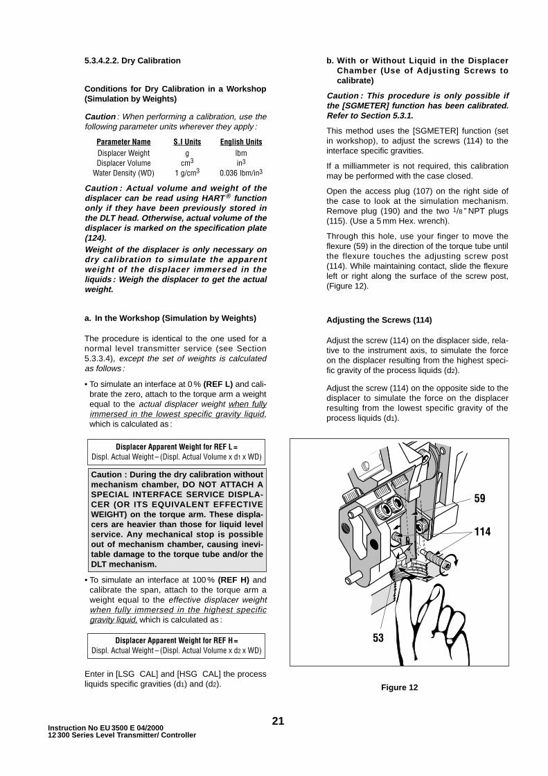
b. With or Without Liquid in the DisplacerChamber (Use of Adjusting Screws tocalibrate)
Caution : This procedure is only possible ifthe [SGMETER] function has been calibrated.Refer to Section 5.3.1.
This method uses the [SGMETER] function (setin workshop), to adjust the screws (114) to theinterface specific gravities.
If a milliammeter is not required, this calibrationmay be performed with the case closed.
Open the access plug (107) on the right side ofthe case to look at the simulation mechanism.Remove plug (190) and the two 1/8 ” NPT plugs(115). (Use a 5 mm Hex. wrench).
Through this hole, use your finger to move theflexure (59) in the direction of the torque tube untilthe flexure touches the adjusting screw post(114). While maintaining contact, slide the flexureleft or right along the surface of the screw post,(Figure 12).
Adjusting the Screws (114)
Adjust the screw (114) on the displacer side, rela-tive to the instrument axis, to simulate the forceon the displacer resulting from the highest speci-fic gravity of the process liquids (d2).
Adjust the screw (114) on the opposite side to thedisplacer to simulate the force on the displacerresulting from the lowest specific gravity of theprocess liquids (d1).
Displacer Apparent Weight for REF H =Displ. Actual Weight – (Displ. Actual Volume x d2 x WD)
Displacer Apparent Weight for REF L =Displ. Actual Weight – (Displ. Actual Volume x d1 x WD)
Figure 12
Caution : During the dry calibration withoutmechanism chamber, DO NOT ATTACH ASPECIAL INTERFACE SERVICE DISPLA-CER (OR ITS EQUIVALENT EFFECTIVEWEIGHT) on the torque arm. These displa-cers are heavier than those for liquid levelservice. Any mechanical stop is possibleout of mechanism chamber, causing inevi-table damage to the torque tube and/or theDLT mechanism.
22Instruction No EU 3500 E 04/2000
12 300 Series Level Transmitter/ Controller
Proceed as follows :
1. Remove the front plate (80). Enter theDIAGNOSTIC Menu then move to [SGME-TER] and accept by .
2. Press the flexure (59) against the adjustingscrew shoulder (114) which corresponds tothe lowest specific gravity, d1. While maintai-ning contact and using a 3 mm hex wrench,turn the adjusting screw until LCD displaysd1.
3. Press the flexure (59) against the adjustingscrew shoulder (114) which corresponds tothe highest specific gravity, d2. While maintai-ning contact and using a 3 mm hex wrench,turn the adjusting screw until LCD displaysd2.
4. Slowly move from one shoulder to the other(to avoid displacer oscillations) and verify thevalue displayed. Correct adjustments ifnecessary.
5. Quit the [SGMETER] function and return to[MANUAL] display.
Calibration with screws (114)
1. Enter the CALIBRATION Menu and move todisplay [CHG SG], then [LSG SER] and[HSG SER]. Read these two values andreturn to [CHG SG].
2. Move to [CAL Z S] then to [LSG CAL] and[HSG CAL] to enter the specific gravities (d1)and (d2).
3. Move to display [ZERO]. Press the flexure(59) to contact the lowest specific gravityadjusting screw (114) (opposite to the displa-cer side). Wait for a few seconds until thedisplacer stabilizes and accept the zerovalue.
4. Move to display [SPAN]. Move the flexure(59) to contact the shoulder of the screw(114) corresponding to the highest specificgravity (on displacer side). Wait a fewseconds until displacer is stable and acceptthe span value.
5. Release the flexure.
6. Complete the calibration as indicated in Steps7 to 15 of the Section 5.3.3.4.
7. Reinstall plugs (107), (190), and (115).
NOTE : If the displacer chamber is empty, theLCD will display an incorrect negative value.
The zero of the LCD is correct only when thedisplacer is fully immersed in the lowestspecific gravity liquid.
Moving the flexure from one shoulder to theother varies the display and the loop currentfrom 0 to 100 %.
6.1 Removing the DLT Case From theTorque Tube (Figures 13, 14, 15 & 21).
a. Switch off power supply. Unscrew (106) until it disen-gages from the case and remove the cover (104) ofthe connection compartment. Disconnect supply wiresfrom terminals (90).
b. Remove cover (107) of the mechanism compartment.Using a 2.5 mm hex wrench, loosen screw (62) touncouple the beam (54) from the torque rod.
c. While holding the case to prevent it from falling, loosenthe four screws (121), using a 5 mm hex wrench, andremove them along with the washers (122). Removethe case by pulling it along the axis of the torque tubewhile being careful to prevent any deformation of thecoupling flexure (70).
CAUTIONS
1. Do not remove the main cover (20) or theconnection compartment cover (104) withoutfirst switching off the power supply or verifyingthat the instrument is installed in an intrinsicallysafe circuit or is not installed in an explosiveatmosphere.
2. Operations described below may require you toopen the mechanism compartment. Before retur-ning the instrument to normal operation, verifythat both covers and the plug are correctly reas-sembled with gaskets in good condition.Use only original Masoneilan parts. Payparticular attention to the plug (190), whichincludes a compressible gasket (192).
6. maintenance
23Instruction No EU 3500 E 04/200012 300 Series Level Transmitter/ Controller
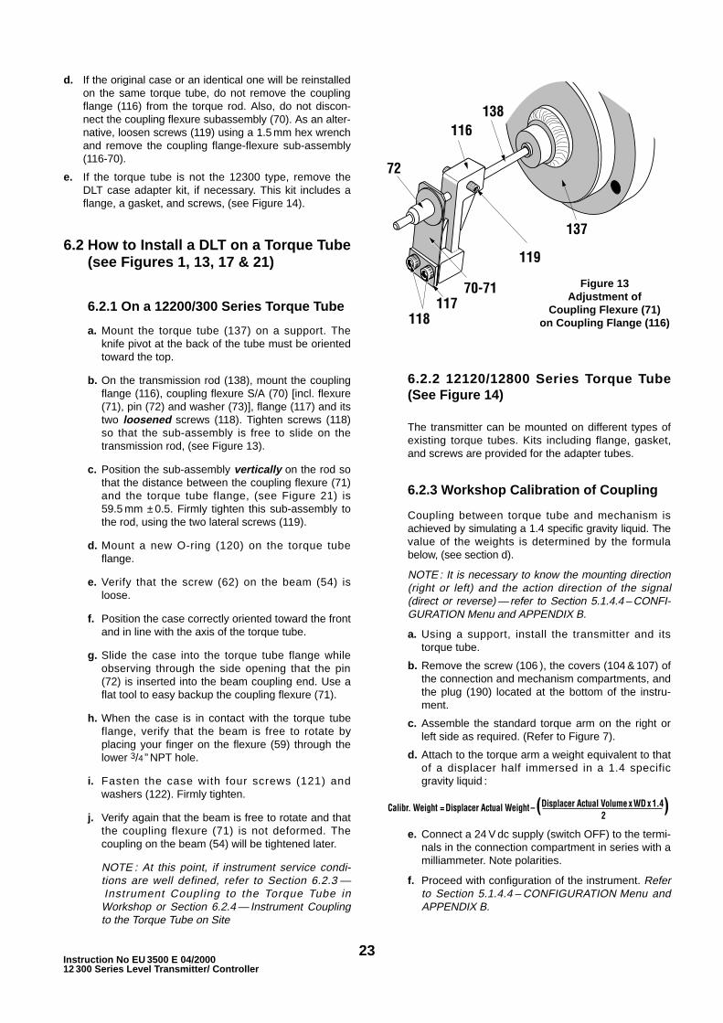
d. If the original case or an identical one will be reinstalledon the same torque tube, do not remove the couplingflange (116) from the torque rod. Also, do not discon-nect the coupling flexure subassembly (70). As an alter-native, loosen screws (119) using a 1.5 mm hex wrenchand remove the coupling flange-flexure sub-assembly(116-70).
e. If the torque tube is not the 12300 type, remove theDLT case adapter kit, if necessary. This kit includes aflange, a gasket, and screws, (see Figure 14).
6.2 How to Install a DLT on a Torque Tube(see Figures 1, 13, 17 & 21)
6.2.1 On a 12200/300 Series Torque Tube
a. Mount the torque tube (137) on a support. Theknife pivot at the back of the tube must be orientedtoward the top.
b. On the transmission rod (138), mount the couplingflange (116), coupling flexure S/A (70) [incl. flexure(71), pin (72) and washer (73)], flange (117) and itstwo loosened screws (118). Tighten screws (118)so that the sub-assembly is free to slide on thetransmission rod, (see Figure 13).
c. Position the sub-assembly vertically on the rod sothat the distance between the coupling flexure (71)and the torque tube flange, (see Figure 21) is59.5 mm ±0.5. Firmly tighten this sub-assembly tothe rod, using the two lateral screws (119).
d. Mount a new O-ring (120) on the torque tubeflange.
e. Verify that the screw (62) on the beam (54) isloose.
f. Position the case correctly oriented toward the frontand in line with the axis of the torque tube.
g. Slide the case into the torque tube flange whileobserving through the side opening that the pin(72) is inserted into the beam coupling end. Use aflat tool to easy backup the coupling flexure (71).
h. When the case is in contact with the torque tubeflange, verify that the beam is free to rotate byplacing your finger on the flexure (59) through thelower 3/4 ” NPT hole.
i. Fasten the case with four screws (121) andwashers (122). Firmly tighten.
j. Verify again that the beam is free to rotate and thatthe coupling flexure (71) is not deformed. Thecoupling on the beam (54) will be tightened later.
NOTE : At this point, if instrument service condi-tions are well defined, refer to Section 6.2.3 —Instrument Coupling to the Torque Tube inWorkshop or Section 6.2.4 — Instrument Couplingto the Torque Tube on Site
6.2.2 12120/12800 Series Torque Tube(See Figure 14)
The transmitter can be mounted on different types ofexisting torque tubes. Kits including flange, gasket,and screws are provided for the adapter tubes.
6.2.3 Workshop Calibration of Coupling
Coupling between torque tube and mechanism isachieved by simulating a 1.4 specific gravity liquid. Thevalue of the weights is determined by the formulabelow, (see section d).
NOTE : It is necessary to know the mounting direction(right or left) and the action direction of the signal(direct or reverse) — refer to Section 5.1.4.4 – CONFI-GURATION Menu and APPENDIX B.
a. Using a support, install the transmitter and itstorque tube.
b. Remove the screw (106 ), the covers (104 & 107) ofthe connection and mechanism compartments, andthe plug (190) located at the bottom of the instru-ment.
c. Assemble the standard torque arm on the right orleft side as required. (Refer to Figure 7).
d. Attach to the torque arm a weight equivalent to thatof a displacer half immersed in a 1.4 specificgravity liquid :
Calibr. Weight = Displacer Actual Weight –(Displacer Actual Volume x WD x 1.4)2
e. Connect a 24 V dc supply (switch OFF) to the termi-nals in the connection compartment in series with amilliammeter. Note polarities.
f. Proceed with configuration of the instrument. Referto Section 5.1.4.4 – CONFIGURATION Menu andAPPENDIX B.
Figure 13Adjustment of
Coupling Flexure (71)on Coupling Flange (116)

24Instruction No EU 3500 E 04/2000
12 300 Series Level Transmitter/ Controller
g. Move to CALIBRATION menu to display[COUPLNG].
h. By looking through the side orifice, verify that thescrew (62) coupling end of the beam (54) is loose.Through the 3/4 ” NPT hole at the bottom of thecase, press the flexure (59) with your finger toverify it is possible to move the beam (54) from leftto right. The value displayed should vary accordin-gly. Pin (72) must rotate freely inside thecoupling end of the beam.
i. Look at the mechanism through the lateral orifice,and index the oval hole of the flexure towards thespecial conical ended pin (53) by bending theflexure (59) toward the case front, (see Figure 15).Note the value read on the LCD — it should bebetween – 5 and + 5 %.
NOTE : At this step, verify that the weight used tosimulate the displacer is stable. To obtain the idealvalue (around 0 %), it may be necessary to slightlybend the flexure towards left or right (while keepingthe conical pin (53) in the oval hole of the flexure).
j. While holding the flexure (59) in that position,slightly but firmly tighten the screw (62) using a2.5 mm Allen wrench.
k. Remove your finger so that the flexure disengagesthe conical pin.
l. Read the value on the LCD. It should remainbetween – 5 and + 5 %.
Figure 14 — Adaptation on 12800 /12120 Torque Tube
ADAPTATION KIT FOR12800 MASONEILAN
TORQUE TUBE EUROPEAN DESIGN
ADAPTATION KIT FOR12120 MASONEILAN
TORQUE TUBEEUROPEAN DESIGN
ADAPTATION KIT FOR12800 & 12120 MASONEILAN
TORQUE TUBEUSA DESIGN
1 O-ring
1 O-ring
1 gasket
4 Lockwashers
4 Lockwashers
4 Lockwashers
1 Adapting Flange
1 Adapting Flange
1 Adapting Flange
4 Hex. H. Screws
4 Hex. H. Screws
4 Hex. H. Screws
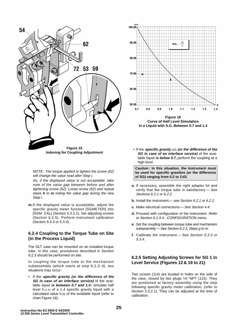
25Instruction No EU 3500 E 04/200012 300 Series Level Transmitter/ Controller
NOTE : The torque applied to tighten the screw (62)will change the value read after Step i.So, if the displayed value is not acceptable, takenote of the value gap between before and aftertightening screw (62). Loose screw (62) and repeatsteps h to m noting the value gap during the newStep i.
m. If the displayed value is acceptable, adjust thespecific gravity meter function [SGMETER] into[SGM CAL] (Section 5.3.2.1). Set adjusting screws(Section 6.2.5). Perform instrument calibration(Section 5.3.3 or 5.3.4).
6.2.4 Coupling to the Torque Tube on Site(in the Process Liquid)
The DLT case can be mounted on an installed torquetube. In this case, procedures described in Section6.2.3 should be performed on site.
In coupling the torque tube to the mechanismsubassembly (which starts at step 6.2.3. d), twosituations may occur :
• If the specific gravity (or the difference of theSG in case of an interface service) of the avai-lable liquid is between 0.7 and 1.4 : simulate halflevel h (1.4) of a 1.4 specific gravity liquid with acalculated value h (d) of the available liquid (refer tochart Figure 16).
• If the specific gravity (d3) (or the difference of theSG in case of an interface service) of the avai-lable liquid is below 0.7, perform the coupling at ahigh level.
a. If necessary, assemble the right adapter kit andverify that the torque tube is satisfactory — SeeSections 6.2.1 or 6.2.2.
b. Install the instrument — see Section 6.2.1 or 6.2.2.
c. Make electrical connections — See Section 4.4.
d. Proceed with configuration of the instrument. Referto Section 5.1.4.4 – CONFIGURATION menu.
e. Set the coupling between torque tube and mechanismsubassembly—See Section 6.2.3, Steps g to m.
f. Calibrate the instrument — See Section 5.3.3 or5.3.4.
6.2.5 Setting Adjusting Screws for SG 1 inLevel Service (Figures 12 & 19 to 21)
Two screws (114) are located in holes on the side ofthe case, closed by two plugs 1/8 ” NPT (115). Theyare positioned at factory assembly using the stepfollowing specific gravity meter calibration, (refer toSection 5.3.2.1). They can be adjusted at the time ofcalibration.
Figure 16Curve of Half Level Simulation
in a Liquid with S.G. Between 0.7 and 1.4
Figure 15Indexing for Coupling Adjustment
Caution : In this situation, the instrument mustbe used for specific gravities (or the differenceof SG) ranging from 0.2 to 2 d3.

26Instruction No EU 3500 E 04/200012 300 Series Level Transmitter/ Controller
These adjusting screws allow the user on site :
• For level interface service : To calibrate theinstrument, with or without liquid, (see Section5.3.4.2.2, b.).
• For liquid level service : To simulate, withoutliquid, a change in level of a specific gravity 1liquid.
In this last case, proceed as follows :
To adjust stops, put the instrument into the precedingcalibrated specific gravity meter function [SGMETER](Refer to APPENDIX D).
Open the access plug (107) to look at the simulationmechanism. Remove the 3/4” NPT plug (190) locatedat the bottom of instrument.
Through the 3/4 ” NPT opening, use your finger tomove the flexure (59) in the direction of the torquetube until it seats on the smooth end of the screws(114). While maintaining pressure, slide the flexure tothe right or the left until it stops against the screwshoulder. See Figure 12.
Relative to the instrument axis, adjust the screw ondisplacer side to simulate a high level of S.G. 1 liquid(REF H). Use the screw on the side opposite to thedisplacer to simulate a low level (REF L) (displacerchamber empty).
In practice, proceed as follows :
a. Simulate low level (REF L) :
In the workshop, attach to the displacer arm aweight equal to actual displacer.
On site, the displacer chamber should be empty.
b. Remove plugs (115) using a 5 mm hex wrench.
c. Using the push buttons, enter the DIAGNOSTICMenu and move to the specific gravity meter func-tion [SGMETER]. Validate by . The LCD display avalue around [ 0.000].
d. With your finger, move the flexure (59) until it seatson the shoulder of the screw opposite to the displa-cer. Adjust screw (114) until LCD displays a valueas close as possible to [ 0.000].
e. Move the flexure (59) until it contacts the shoulderof the displacer side screw. Adjust screw until LCDdisplays a value as close as possible to [ 1.000].
f. Quit the DIAGNOSTIC Menu and return toNORMAL Operation.
g. Release the flexure.
h. Reassemble the plugs (115-107-190).
6.3 Removing a Torque Tube withassembled DLT Case (see Figure 17)
a. Switch off power supply.
b. For instruments with a displacer chamber, closeisolation valves, and purge the chamber.
c. Remove upper flange (146) and blind flange (144).
d. Lower the torque arm (135) and unhook the displa-cer (130). A hook-shaped 3 mm steel wire will facili-tate unhooking and holding of the displacer. Thewire may be inserted through the clevis hole.
e. Remove the two torque arm screws (133) andremove the torque arm (135) from the chamber.
f. Remove displacer from its chamber (131) or tank.
g. Be sure that requirements for instruments installedin explosive areas are strictly followed.
Remove screw (106) from connection compartmentand unscrew cover (104). Disconnect supply elec-trical wires and other equipment from terminals(90).
h. Remove nuts (142) holding the torque tube sub-assembly and slide the subassembly out of themechanism chamber.
130.Displacer131.Displacer Chamber132. Internal Knife Edge Block133.Torque Arm Screw134.Torque Arm Block135.Torque Arm137.Torque Tube Housing
Assembly
142.Stud Nut143.Gasket144.Blind Flange145.Stud146.Top Flange147.Top Flange Stud148.Top Flange Stud Nut149.Top Flange Gasket
PARTS REFERENCE
Figure 17
Caution : This procedure is only possible if the[SGMETER] function has been calibrated. Referto Section 5.3.1.
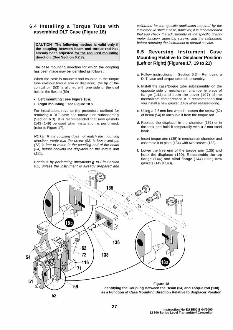
27Instruction No EU 3500 E 04/2000
12 300 Series Level Transmitter/ Controller
6.4 Install ing a Torque Tube withassembled DLT Case (Figure 18)
The case mounting direction for which the couplinghas been made may be identified as follows :
When the case is mounted and coupled to the torquetube (without torque arm or displacer), the tip of theconical pin (53) is aligned with one side of the ovalhole in the flexure (59) :
• Left mounting : see Figure 18 a.• Right mounting : see Figure 18 b.
For installation, reverse the procedure outlined forremoving a DLT case and torque tube subassembly(Section 6.3). It is recommended that new gaskets(143 - 149) be used when installation is performed,(refer to Figure 17).
NOTE : If the coupling does not match the mountingdirection, verify that the screw (62) is loose and pin(72) is free to rotate in the coupling end of the beam(54) before hooking the displacer on the torque arm(135).
Continue by performing operations g to i in Section6.5, unless the instrument is already prepared and
calibrated for the specific application required by thecustomer. In such a case, however, it is recommendedthat you check the adjustments of the specific gravitymeter function, adjusting screws, and the calibration,before returning the instrument to normal service.
6.5 Reversing Instrument CaseMounting Relative to Displacer Position(Left or Right) (Figures 17, 19 to 21)
a. Follow instructions in Section 6.3 — Removing aDLT case and torque tube sub-assembly.
b. Install the case/torque tube subassembly on theopposite side of mechanism chamber in place offlange (144) and open the cover (107) of themechanism compartment. It is recommended thatyou install a new gasket (143) when reassembling.
c. Using a 2,5 mm hex wrench, loosen the screw (62)of beam (54) to uncouple it from the torque rod.
d. Replace the displacer in the chamber (131) or inthe tank and hold it temporarily with a 3 mm steelhook.
e. Insert torque arm (135) in mechanism chamber andassemble it to plate (134) with two screws (133).
f. Lower the free end of the torque arm (135) andhook the displacer (130). Reassemble the topflange (146) and blind flange (144) using newgaskets (149 & 143).
Figure 18Identifying the Coupling Between the Beam (54) and Torque rod (138)
as a Function of Case Mounting Direction Relative to Displacer Position
CAUTION : The following method is valid only ifthe coupling between beam and torque rod hasalready been adjusted for the required mountingdirection. (See Section 6.2.3).

28Instruction No EU 3500 E 04/2000
12 300 Series Level Transmitter/ Controller
g. Remove the front plate (80) located in front of theinstrument to gain access to the push buttons (27).
h. Enter the CONFIGURATION Menu and select therequired configuration data corresponding to thenew instrument position (refer to Section 5.1.4.4and APPENDIX B).
i. Perform the coupling adjustment according toSection 6.2.4. If necessary, calibrate the specificgravity meter function and set adjusting screws perSections 5.3.2.1 and 6.2.5. Proceed with calibrationfollowing Sections 5.2, 5.3.3 or 5.3.4.
NOTE : The specific gravity meter function and theadjusting screws are features of the transmitter. Theypermit a user to perform simulations that facilitatecalibration in situations such as a no liquid low levelwhen special interface displacers are used and forcalibration with or without liquid in case of a levelinterface using a standard displacer. If such conditionsare not present, however, these adjustments areoptional.
6.6 Replacing the Amplifier and/or theSensor
6.6.1 Removing (Figures 10, 19 & 21)
a. Switch off power supply. Partially unscrew safetyscrew (110) from main cover (20) so that it disen-gages from the case. Remove main cover (20).
b. Progressively and alternatively loosen the fourscrews (201) to remove the amplifier (200).
c. Disconnect the sensor connector (40) and connec-tor (7) from the back of amplifier (200).
d. If the sensor shall be removed, unscrew the twoscrews (112) and remove the sensor (40) and itsO-ring (111).
6.6.2 Installing (See Figures 10, 19 & 21)
a. If the sensor has been removed, slide the newsensor, equipped with new O-ring (111), into thecase while observing the following :
• Orient the blue point toward the center of thecase (another blue mark on the back of the casehelps to verify correct position of the sensor).
• Do not turn the sensor while sliding into the case.
• Maintain horizontal alignment of both holes,especially at the end of the insertion proce-dure.
• Insert and tighten the two screws (112).
b. Connect the sensor connector (40) and connector(7) at the back of amplifier (200). Take care tocorrect position by means of the locking lugs.(above for the (40) connector and below for the(7) one). Refer to Figures 19 and 21.
c. Insert the amplifier (200) with four screws (201)inserted into the front of the case with the LCDfacing the top.
d. Progressively and alternately insert the four screws(201) while pushing the amplifier against thebottom of the case. Tighten the four screws.
e. Close the main cover (20) and tighten safety screw(110). Switch on the power supply.
f. Configure the transmitter for the required servicecharacteristics. Refer to Section 5.1.4.4.
g. Calibrate the specific gravity meter function andperform calibration. Refer to proper Sections 6.2.5& 5.2 or 5.3.). Return to NORMAL Operating Mode.
6.7 Replacing the Mechanism Sub-assembly (50), (Figures 20 & 21)
6.7.1 Removing
a. Switch off power supply. Unscrew safety screw(106) enough to disengage it from case. Removecover (104) of the connection compartment.Disconnect supply wires from terminals (90).
b. Remove cover (107) of mechanism compartment.Using a 2.5 mm hex wrench, loosen screw (62) onbeam (54) to uncouple it from the transmission rod.
c. While holding the case to prevent it from falling,loosen the four screws (121) with a 5 mm hexwrench and remove them and the associatedwashers (122). Remove the case by pulling it alongthe axis of the torque tube, using care to preventany deformation of the coupling flexure (70).
NOTE : Do not remove flange (116) from torque rod(138) nor the coupling flexure subassembly (70).
d. Using a 3 mm hex wrench, remove the two screws(113) that fasten the mechanism subassembly tothe case.
CAUTION: Parts which constitute the mechanismsubassembly (50), including elements (51 to 62)are assembled at the factory using high precisiontools that guarantee highly accurate positioning,which is required to achieve specifiedperformance. They should never beendisassembled unless a malfunction occurs. Thewhole sub-assembly must then be replaced orreturned to the factory for rebuild.
CAUTION : Do not pull on the sensor wires toremove the sensor from the case. Be carefulnot to damage the sensor or mechanismsubassembly during this operation.

29Instruction No EU 3500 E 04/200012 300 Series Level Transmitter/ Controller
Figure 19Type 12300 Transmitter
External View of Case,Cover and Amplifier Removed
Figure 20
Type 12300 TransmitterFront View
Type 12300 TransmitterCross Section View
From Back

30Instruction No EU 3500 E 04/200012 300 Series Level Transmitter/ Controller
Ref. Qty Parts Name Ref. Qty Parts Name Ref. Qty Parts NameNo No No
1 1 Case S/A (incl. 2 to 9)2 1 Case
3 2 Radio Frequency Filter7 1 Connecting Plug8 1 Isolated Red Wire9 1 Isolated Black Wire
20 1 Main Cover S/A(incl. 21 to 27)
21 1 Main Cover22 1 Window23 1 Truarc Ring
24 1 O-Ring (Front Plate)25 3 Button Spring26 3 Button Axis27 3 Button40 1 Sensor S/A50 1 Mechanism S/A
(incl. 51 to 62)51 1 Pivot52 1 Drive Pin53 1 Conical Pin54 1 Beam55 2 Magnet56 2 “U” Flexure57 4 Flange (Flexure)58 8 Screw (Fastening of Flexure)59 1 Adjusting Flexure60 1 Screw (Fast.ng of Adj.ng Flexure)
61 1 Washer62 1 Adjusting Screw70 1 Coupling Flexure S/A
(incl. 71 to 73)71 1 Coupling Flexure72 1 Pin73 1 Coupling Flexure Washer80 1 Front Plate S/A90 1 Terminal Board
90A 1 Flat Handle Terminal Block90B 1 Terminal Board Connector
92 2 Screw (Term. Board Fastening)93 2 Washer (Term. Board Fastening)94 2 Lockwasher (Term. Board Fast.ng)95 1 Washer96 1 Clamp97 1 Screw (Clamp)98 1 Lockwasher99 1 Washer
100 1 Clamp101 1 Screw (Clamp)102 1 Washer103 1 Caplug (Only for Shipment)104 1 Connection Compartment Cover
105 1 O-Ring (Connection Compart.nt)106 1 Screw (Connection Compartment)107 1 Access Plug
108 1 O-Ring (Access Plug) 109 1 O-Ring (Main Cover)
110 1 Safety Screw (Main Cover) 111 1 O-Ring (Sensor)
112 2 Screw (Fast.ng of sensor)113 2 Screw (Fast.ng of Mechan. S/A)114 2 Adjusting Screw115 2 1/8” NPT Plug (Adjusting Screw)116 1 Coupling Flange117 1 Flexure Flange118 2 Screw (Fastening of
Coupling Flexure/Flange)119 2 Screw (Fast.ng of Coupling Fl.
on Torque T Transm. Rod) 120 1 O-Ring (Case S/A on T. Tube)
121 4 Screw (Fast.ng of Case S/A on TT.)122 4 Lockwasher123 4 Drive Screw124 1 Specifications Plate125 3 Screw (Front Plate/Main Cover)
126 3 O-Ring (Screw 125) 190 1 3/4” NPT Plug S/A
(incl. 191 & 192)191 1 3/4”NPT Plug192 1 Spongy Gasket200 1 Type 300 Circuit Board S/A201 4 Screw
Recommended Spare PartsBold Type : No Dissociable Sub-assembly
Not Shown
Figure 21 — Cross Section of Type 12300 Electronic Level Transmitter
PARTS REFERENCE

31Instruction No EU 3500 E 04/2000
12 300 Series Level Transmitter/ Controller
7.1 No Signal :
• Check connection wires to transmitter.
• Check polarities.
• Verify the correct position of the connectors (7) and(40) on the amplifier, (refer to Figures 19 & 21).
7.2 No Display but Signal Exists :
• Replace the amplifier.
7.3 Signal is Steady, No Change When LevelVaries:
• In case of an external maounting (see 3.2.1),check that the immobilization of the displacer inthe displacer chamber (for transportationpurpose), has been removed.
• Verify that the instrument is not in FAILSAFEMode. If not, verify that the instrument display theNormal Operating screen [the instrument displaysalternatively the loop current and the level expres-sed in the unit (% or engineering unit)],
• Verify coupling between transmission rod mecha-nism subassembly by moving flexure (59), whichallows you to simulate a level change,
• Move to [SNR TST] in the DIAGNOSTIC Menu toverify Hall effect sensor. Refer to APPENDIX D.
7.4 If current output is not the same that currentdisplayed :
DANGER : Full compliance with standardsrequirements for instruments installed inhazardous areas must be insured.
• Verify the current loop is in accordance with §4.4.3. That is to say the voltage on the HDLTterminal board must be equal or greater than 9,5V.
• Insert a reference milliammeter in series with thepower supply or connect it to the electronic boardprovided into the connection compartment,
Put the switch on the “TEST” position. Connect
the milliammeter on the two pins located on eachside of the switch,
• To recalibrate the internal milliammeter, move tosub-menu [4 20 MA] via [CALIBR ] in the CALI-BRATION Menu. Refer to APPENDIX C,
• Move to [4 MA] then display [ – +####] by .Decrease or increase value (ranges from 2900 to3500 increment 1) until the reference milliammeterindicates 4.000 mA. Push again to return to[4 MA],
• Move to [20 MA] then display [ – +####] by .Decrease or increase value (ranges from 2000 to3500 increment 1) until the reference milliammeterindicates 20.000 mA. Push again to return to[20 MA],
• Move to [MA GENE] to generate different outputcurrent to verify the current loop regarding thereference milliammeter,
• Move until [<– ] is displayed and press to storedata via [STORAGE] and [YES NO] screens, thenreturn to the [4 20 mA],
• When the setting is completed, move into themenu until [<–MANU] is displayed, then press toexit the CALIBRATION Menu and to display[MANUAL],
• Press , –, : [NORMAL] appears for a fewseconds and the instrument automatically returnsto Normal Operating display,
• Before disconnecting the milliammeter put theswitch back on the position identified by “”. SeeFigure 19.
7.5 No HART communication :
DANGER : Full compliance with standardsrequirements for instruments installed inhazardous areas must be insured.
• Verify the current loop is in accordance with §4.4.3. That is to say the voltage on the HDLTterminal board must be equal or greater than 9,5V.
NOTE : After removing the two screws (113),dismounting the mechanism subassembly will befacilitated by using a M5 threaded rod with aboutfour threads engaged in pivot (51) in place of rightscrew (113). The same threaded rod will also beuseful during reassembly. (See Figures 20 & 21).
6.7.2 Installing
a. Install the new mechanism subassembly by enga-ging the two pins (52 & 53) in the case holes.
b. Assemble the two screws (113) and tighten themprogressively and alternately. Be sure that pivot(51) perfectly contacts the back surface of the caseso that the beam (54) will move in a plane strictlyparallel to this surface.
c. Place a new gasket (120) on the torque tubeflange. Verify that screw (62) of the coupling part ofbeam (54) is loose.
d. Continue the procedure by performing steps f to j ofSection 6.2.1. — Mounting a DLT case on a torquetube.
e. Adjust coupling (Refer to proper Section 6.2.3 or6.2.4).
f. Calibrate the specific gravity meter function, (Referto Section 5.3.2.1). Set adjusting screws, (Refer toSection 6.2.5).
g. Recalibrate the instrument, (Refer to properSection 5.2, 5.3.3 or 5.3.4)
7. trouble shooting
32Instruction No EU 3500 E 04/200012 300 Series Level Transmitter/ Controller
• Verify the Hart communication has been enable inthe CONFIGURE MENU - See APPENDIX A[-> INFO] or APPENDIX B [CONFIG].
7.6 The current output doesn’t match with thefluid level (linearity issue) :
• Check the calibration parameters.
• For a standard displacer (1362 g), when using thefunction coupling [COUPLING] in the calibrationmenu, for the zero (lower level), the given valueshall be greater than -37% for a left hand moun-ting or lower than 37% for a right hand mounting.
• Check that the torque arm is horizontal withoutdisplacer.
• Recalibrate the transmitter.
• If the problem remains, contact our After-Salesdepartment.

Instruction No EU 3500 E 04/200012 300 Series Level Transmitter/ Controller
APPENDIX A

Instruction No EU 3500 E 04/200012 300 Series Level Transmitter/ Controller
LIMITS Set if : specific gravity of calibration or service is below .01 for level transmitteror difference of specific gravities of calibration or service is below .01 forinterface transmitter.Set if : displacer characteristics specified in the transmitter data base are notadapted regarding specific gravity of calibration or specific gravity used.
CALIBRATION Transmitter / Sgmeter calibration impossible regarding tests : Tank empty or fullleft or right mounting.
MOUNTING Mounting configuration (left or right) conflicts ZERO and SPAN transmittercalibration : Recoupling torque tube is necessary or recalibrate.
DISPLACER Set if :• Level range ([LEVEL H] – [LEVEL L]) expressed in engineering unit (length) is
greater than the displacer height entered in the instrument data base.
• Instrument configured for interface and the Low Specific Gravity of Service[LSG SER] is set to a value smaller than Low Specific Gravity of Calibration[LSG CAL].
TEMPERATURE Temperature sensor on electronic board out of service or board temperature outof normal range (< – 50 °C or > 100 °C).
HARDWARE Voltage reference out of normal range or E2 PROM write procedure failed.
SOFTWARE No refreshed data from the A/D converter or watch dog set : Software in closedloop or bad main logic initialization.
HALL Sensor disconnected or sensor fault (set during [SNR TST] in DIAGNOSTICMenu) or Hall output out of electronic board input or Hall current incorrect.
CLEAR FAULT Validate by to perform CLEAR FAULT procedure.
SUCCESS Indicates that procedure has been correctly executed.
RESET STANDARD Validate by to return instrument to factory settings :
CONFIGURATION CALIBRATION DIAGNOSTIC FILLING
STORAGE Validate by to start the storage procedure of the “resetted to standard”parameters in the instrument memory. Storage of standard configuration andcalibration will be effective only after completion of next step. It is necessary to go through this step to return to Failsafe sub-menu.
YES NO Validate by (YES) to finalize the storing procedure of the “resetted to standard”parameters. Pushing + or – (NO) will abort the storage ; the configuration andcalibration parameters set previously will stay in the instrument memory.
ABORT Validate by to avoid running the Reset to Standard procedure.
AFTER A “RESET STANDARD” ALL PARAMETERS SHALL BE DONE AGAIN
1.0HSG SER
0.00SPAN >–<
0.0LSG SER
0.00ZERO <–>
1.0HSG CAL0/0
0.0ALRML 0
0.0LSG CAL
100.LEVEL H
3.600FAIL 0
0.0TIME W
0.0LEVEL LENGLISHCTRL 0
0.1W VAL
0.0TIME H
1.000SGM CAL
20.000MA H
– 1.0TIME 2DIRECT
0.61DZ INTG
0.0TIME L
1.000SG SER
4.000MA L
– 1.0TIME 1LEFT
4.0W INTG
0.0FILLING
1.000SG CAL
0.0DAMPING
100.0ALRMH 0LEVEL
COLD RESTART Fugitive display appearing when the instrument is powered on after a long powercut.
WARM RESTART Fugitive display appearing when the instrument is powered on after a micropower cut.
Display the value of the level or interface plan in the unit indicated in low leftcorner.
Display the value of the output current in mA.
NORMAL In NORMAL MODE the screen displays in sequence the value of the level and ofthe output current. Validate by to return to [NORMAL ].
MANUAL Validate by to go to MANUAL MODE Menu.
MANUAL Validate by /–/+ to enter sub-menu [–>CONFG ], [–>CALIB ], [–>DIAGN ] andexit by [–>NORM ].
CONFIGURATION Validate by to go to CONFIGURATION Menu.
CALIBRATION Validate by to go to CALIBRATION Menu.
DIAGNOSTIC Validate by to go to DIAGNOSTIC Menu.
INFORMATION Validate by to read the various informations stored in the memory of theinstrument.
CONFIGURATION Validate by to read the actual configuration data.
CALIBRATION Validate by to read the actual calibration data.
DIAGNOSTIC Validate by to read the actual diagnostic data.
FAULT Validate by to read the possible fault(s) which may have occured since the last“CLEAR FAULT” was performed.
CLEAR FAULT Validate by to read informations on the cleared faults.
FAILSAFE Displayed when instrument has gone to Failsafe mode ; this may occur when :• The alarm(s) have been set on and the level is higher than [ALRMH ] or lower
than [ALRML ].• The Hall effect sensor is disconnected.• The current loop is frozen to :
- The last value before going to FAILSAFE if [FAIL O] was selected inCONFIGURATION Menu.
- The value set if [FAIL I] was configured.
Display the loop current value during FAILSAFE Mode. The current value isalternatively displayed with the message "FAILSAF"
FAULT Validate by to know the fault which has induced going to FAILSAFE Mode.
NO FAULT
FACTORY Set in CALIBRATION Menu if “RESET STANDARD” is performed and SPECIFICGRAVITY METER has never been previously calibrated by the Factory.
START Set after every power on or HART ® reset command.
HIGH ALARM Set after TIME 1 has elapsed with level (in engineering unit) > [H ALARM] ± 5%.Set if TIME 2 has elapsed.
LOW ALARM Set after TIME 1 has elapsed with level (in engineering unit) < [L ALARM] ± 5%.Set if TIME 2 has elapsed.
NORMAL MODE, MANUAL MODE, FAILSAFE MODE AND INFORMATION MENU SCREENS DESCRIPTION APPENDIX A
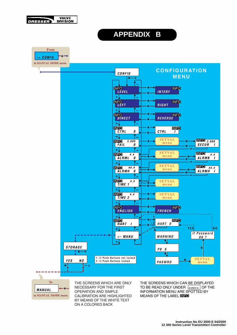
Instruction No EU 3500 E 04/200012 300 Series Level Transmitter/ Controller
APPENDIX B
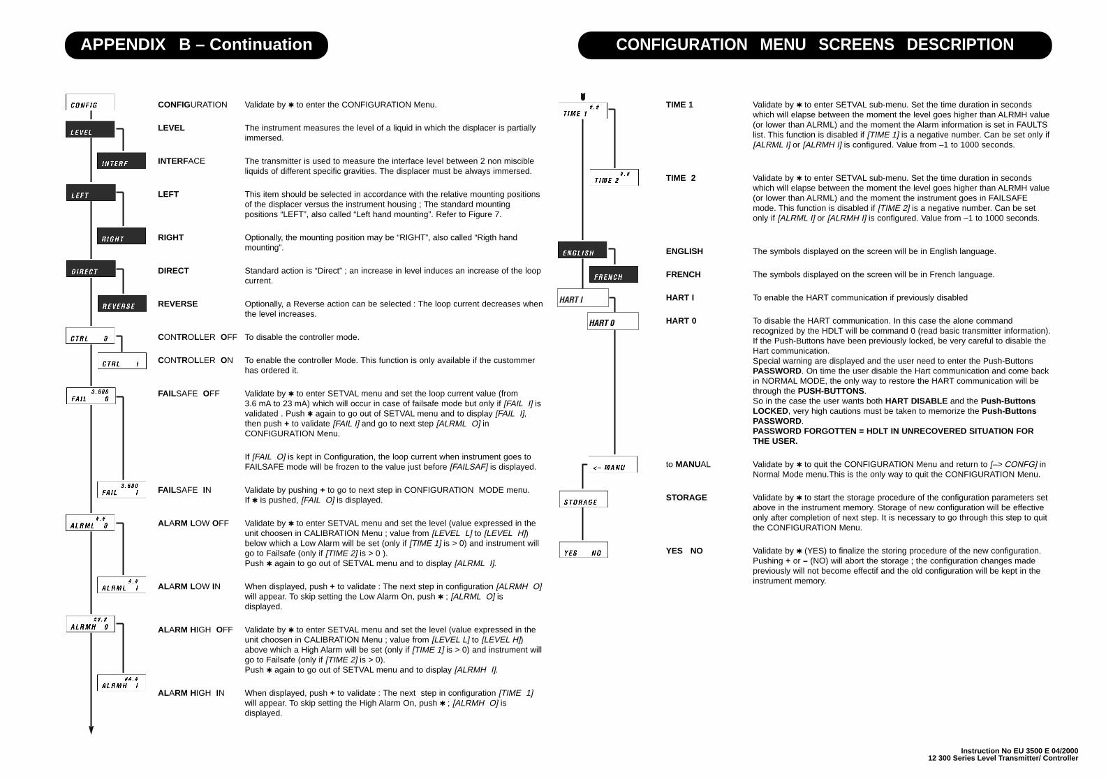
Instruction No EU 3500 E 04/200012 300 Series Level Transmitter/ Controller
TIME 1 Validate by to enter SETVAL sub-menu. Set the time duration in secondswhich will elapse between the moment the level goes higher than ALRMH value(or lower than ALRML) and the moment the Alarm information is set in FAULTSlist. This function is disabled if [TIME 1] is a negative number. Can be set only if[ALRML I] or [ALRMH I] is configured. Value from –1 to 1000 seconds.
TIME 2 Validate by to enter SETVAL sub-menu. Set the time duration in secondswhich will elapse between the moment the level goes higher than ALRMH value(or lower than ALRML) and the moment the instrument goes in FAILSAFEmode. This function is disabled if [TIME 2] is a negative number. Can be setonly if [ALRML I] or [ALRMH I] is configured. Value from –1 to 1000 seconds.
ENGLISH The symbols displayed on the screen will be in English language.
FRENCH The symbols displayed on the screen will be in French language.
HART I To enable the HART communication if previously disabled
HART 0 To disable the HART communication. In this case the alone commandrecognized by the HDLT will be command 0 (read basic transmitter information).If the Push-Buttons have been previously locked, be very careful to disable theHart communication.Special warning are displayed and the user need to enter the Push-ButtonsPASSWORD. On time the user disable the Hart communication and come backin NORMAL MODE, the only way to restore the HART communication will bethrough the PUSH-BUTTONS.So in the case the user wants both HART DISABLE and the Push-ButtonsLOCKED, very high cautions must be taken to memorize the Push-ButtonsPASSWORD.PASSWORD FORGOTTEN = HDLT IN UNRECOVERED SITUATION FORTHE USER.
to MANUAL Validate by to quit the CONFIGURATION Menu and return to [–> CONFG] inNormal Mode menu.This is the only way to quit the CONFIGURATION Menu.
STORAGE Validate by to start the storage procedure of the configuration parameters setabove in the instrument memory. Storage of new configuration will be effectiveonly after completion of next step. It is necessary to go through this step to quitthe CONFIGURATION Menu.
YES NO Validate by (YES) to finalize the storing procedure of the new configuration.Pushing + or – (NO) will abort the storage ; the configuration changes madepreviously will not become effectif and the old configuration will be kept in theinstrument memory.
CONFIGURATION Validate by to enter the CONFIGURATION Menu.
LEVEL The instrument measures the level of a liquid in which the displacer is partiallyimmersed.
INTERFACE The transmitter is used to measure the interface level between 2 non miscibleliquids of different specific gravities. The displacer must be always immersed.
LEFT This item should be selected in accordance with the relative mounting positionsof the displacer versus the instrument housing ; The standard mountingpositions “LEFT”, also called “Left hand mounting”. Refer to Figure 7.
RIGHT Optionally, the mounting position may be “RIGHT”, also called “Rigth handmounting”.
DIRECT Standard action is “Direct” ; an increase in level induces an increase of the loopcurrent.
REVERSE Optionally, a Reverse action can be selected : The loop current decreases whenthe level increases.
CONTROLLER OFF To disable the controller mode.
CONTROLLER ON To enable the controller Mode. This function is only available if the custommerhas ordered it.
FAILSAFE OFF Validate by to enter SETVAL menu and set the loop current value (from3.6 mA to 23 mA) which will occur in case of failsafe mode but only if [FAIL I] isvalidated . Push again to go out of SETVAL menu and to display [FAIL I],then push + to validate [FAIL I] and go to next step [ALRML O] inCONFIGURATION Menu.
If [FAIL O] is kept in Configuration, the loop current when instrument goes toFAILSAFE mode will be frozen to the value just before [FAILSAF] is displayed.
FAILSAFE IN Validate by pushing + to go to next step in CONFIGURATION MODE menu.If is pushed, [FAIL O] is displayed.
ALARM LOW OFF Validate by to enter SETVAL menu and set the level (value expressed in theunit choosen in CALIBRATION Menu ; value from [LEVEL L] to [LEVEL H])below which a Low Alarm will be set (only if [TIME 1] is > 0) and instrument willgo to Failsafe (only if [TIME 2] is > 0 ). Push again to go out of SETVAL menu and to display [ALRML I].
ALARM LOW IN When displayed, push + to validate : The next step in configuration [ALRMH O]will appear. To skip setting the Low Alarm On, push ; [ALRML O] isdisplayed.
ALARM HIGH OFF Validate by to enter SETVAL menu and set the level (value expressed in theunit choosen in CALIBRATION Menu ; value from [LEVEL L] to [LEVEL H])above which a High Alarm will be set (only if [TIME 1] is > 0) and instrument willgo to Failsafe (only if [TIME 2] is > 0). Push again to go out of SETVAL menu and to display [ALRMH I].
ALARM HIGH IN When displayed, push + to validate : The next step in configuration [TIME 1]will appear. To skip setting the High Alarm On, push ; [ALRMH O] isdisplayed.
CONFIGURATION MENU SCREENS DESCRIPTIONAPPENDIX B – Continuation
HART I
HART 0
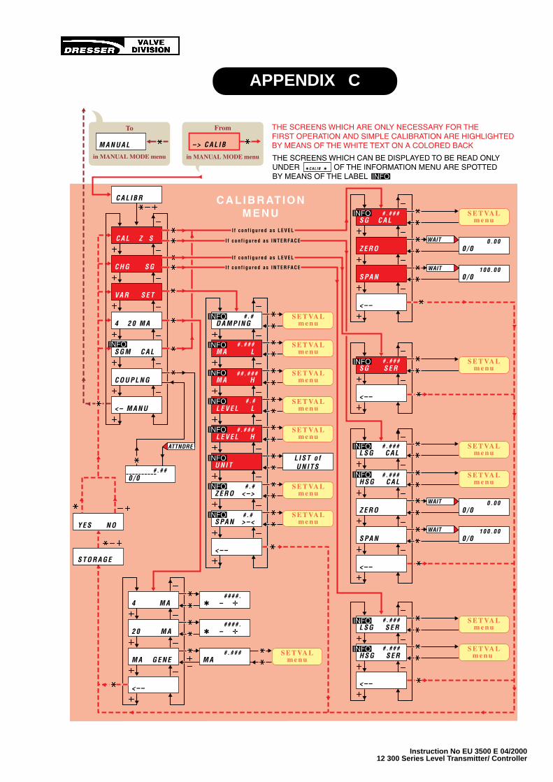
Instruction No EU 3500 E 04/200012 300 Series Level Transmitter/ Controller
APPENDIX C
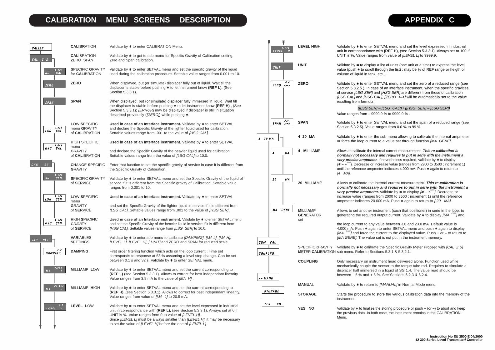
Instruction No EU 3500 E 04/200012 300 Series Level Transmitter/ Controller
LEVEL HIGH Validate by to enter SETVAL menu and set the level expressed in industrialunit in correspondance with (REF H), (see Section 5.3.3.1). Always set at 100 ifUNIT is %. Value ranges from value of [LEVEL L] to 9999.9.
UNIT Validate by to display a list of units (one unit at a time) to express the levelvalue (push + to scroll through the list) ; may be % of REF range or heigth orvolume of liquid in tank, etc…
ZERO Validate by to enter SETVAL menu and set the zero of a reduced range (seeSection 5.3.2.5 ). In case of an interface instrument, when the specific gravitiesof service [LSG SER] and [HSG SER] are different from those of calibration[LSG CAL] and [HSG CAL], [ZERO <–>] will be automatically set to the valueresulting from formula :
([LSG SER] – [LSG CAL]) / ([HSG SER] – [LSG SER])
Value ranges from – 9999.9 % to 9999.9 % .
SPAN Validate by to enter SETVAL menu and set the span of a reduced range (see Section 5.3.2.5). Value ranges from 0.0 % to 99 %.
4 20 MA Validate by to enter the sub-menu allowing to calibrate the internal ampmeteror force the loop current to a value set through function [MA GENE].
4 MILLIAMP Allows to calibrate the internal current measurement. This re-calibration isnormally not necessary and requires to put in serie with the instrument avery precise ampmeter. If nevertheless required, validate by to display[ – +
####]. Decrease or increase value (ranges from 2900 to 3500 ; increment 1)
until the reference ampmeter indicates 4.000 mA. Push again to return to[4 MA].
20 MILLIAMP Allows to calibrate the internal current measurement. This re-calibration isnormally not necessary and requires to put in serie with the instrument avery precise ampmeter. Validate by to display [ – +
####]. Decrease or
increase value (ranges from 2000 to 3500 ; increment 1) until the referenceampmeter indicates 20.000 mA. Push again to return to [ 20 MA].
MILLIAMP Allows to set another instrument (such that positioner) in serie in the loop, toGENERATOR generating the required output current. Validate by to display [MA
#.###] and
set the loop current to any value between 3.6 and 23.0 mA. Default value is4.000 mA. Push again to enter SETVAL menu and push again to display[MA
#.###] and force the current to the displayed value. Push + or – to return to
[MA GENE]. The value set is not put in the instrument memory.
SPECIFIC GRAVITY Validate by to calibrate the Specific Gravity Meter Proceed with [CAL Z S] METER CALIBRATION sub-menu. Refer to Sections 5.3.1 & 5.3.2.1.
COUPLING Only necessary on instrument head delivered alone. Function used whilemechanically couple the sensor to the torque tube rod. Requires to simulate adisplacer half immersed in a liquid of SG 1.4. The value read should bebetween – 5 % and + 5 %. See Sections 6.2.3 & 6.2.4.
MANUAL Validate by to return to [MANUAL] in Normal Mode menu.
STORAGE Starts the procedure to store the various calibration data into the memory of theinstrument.
YES NO Validate by to finalize the storing procedure or push + (or –) to abort and keepthe previous data. In both case, the instrument remains in the CALIBRATIONMenu.
CALIBRATION Validate by to enter CALIBRATION Menu.
CALIBRATION Validate by to get to sub-menu for Specific Gravity of Calibration setting,ZERO SPAN Zero and Span calibration.
SPECIFIC GRAVITY Validate by to enter SETVAL menu and set the specific gravity of the liquid for CALIBRATION used during the calibration procedure. Settable value ranges from 0.001 to 10.
ZERO When displayed, put (or simulate) displacer fully out of liquid. Wait till thedisplacer is stable before pushing to let instrument know (REF L). (SeeSection 5.3.3.1).
SPAN When displayed, put (or simulate) displacer fully immersed in liquid. Wait tillthe displacer is stable before pushing to let instrument know (REF H) , (SeeSection 5.3.3.1); [ERROR] may be displayed if displacer is still in situationdescribed previously ([ZERO]) while pushing .
LOW SPECIFIC Used in case of an Interface instrument. Validate by to enter SETVALmenu GRAVITY and declare the Specific Gravity of the lighter liquid used for calibration. of CALIBRATION Settable values range from .001 to the value of [HSG CAL].
HIGH SPECIFIC Used in case of an Interface instrument. Validate by to enter SETVALmenu GRAVITY and declare the Specific Gravity of the heavier liquid used for calibration. of CALIBRATION Settable values range from the value of [LSG CAL] to 10.0.
CHANGE SPECIFIC Enter that function to set the specific gravity of service in case it is different fromGRAVITY the Specific Gravity of Calibration.
SPECIFIC GRAVITY Validate by to enter SETVAL menu and set the Specific Gravity of the liquid of of SERVICE service if it is different from the Specific gravity of Calibration. Settable value
ranges from 0.001 to 10.
LOW SPECIFIC Used in case of an Interface instrument. Validate by to enter SETVALmenu GRAVITY and set the Specific Gravity of the lighter liquid in service if it is different from of SERVICE [LSG CAL]. Settable values range from .001 to the value of [HSG SER] .
HIGH SPECIFIC Used in case of an Interface instrument. Validate by to enter SETVAL menu GRAVITY and set the Specific Gravity of the heavier liquid in service if it is different from of SERVICE [HSG CAL]. Settable values range from [LSG SER] to 10.0.
VARIABLES Validate by to enter sub-menu to calibrate [DAMPING], [MA L], [MA H],SETTINGS [LEVEL L], [LEVEL H], [ UNIT] and ZERO and SPAN for reduced scale.
DAMPING First order filtering function which acts on the loop current ; Time setcorresponds to response at 63 % assuming a level step change. Can be setbetween 0.1 s and 32 s. Validate by to enter SETVAL menu.
MILLIAMP LOW Validate by to enter SETVAL menu and set the current corresponding to(REF L) (see Section 5.3.3.1). Allows to correct for best independant linearity.Value ranges from 3.8 mA to the value of [MA H] .
MILLIAMP HIGH Validate by to enter SETVAL menu and set the current corresponding to(REF H), (see Section 5.3.3.1). Allows to correct for best independant linearity.Value ranges from value of [MA L] to 20.5 mA.
LEVEL LOW Validate by to enter SETVAL menu and set the level expressed in industrialunit in correspondance with (REF L), (see Section 5.3.3.1). Always set at 0 ifUNIT is %. Value ranges from 0 to value of [LEVEL H] .Since [LEVEL L] must be always smaller than [LEVEL H], it may be necessaryto set the value of [LEVEL H] before the one of [LEVEL L].
CALIBRATION MENU SCREENS DESCRIPTION APPENDIX C

Instruction No EU 3500 E 04/200012 300 Series Level Transmitter/ Controller
APPENDIX D
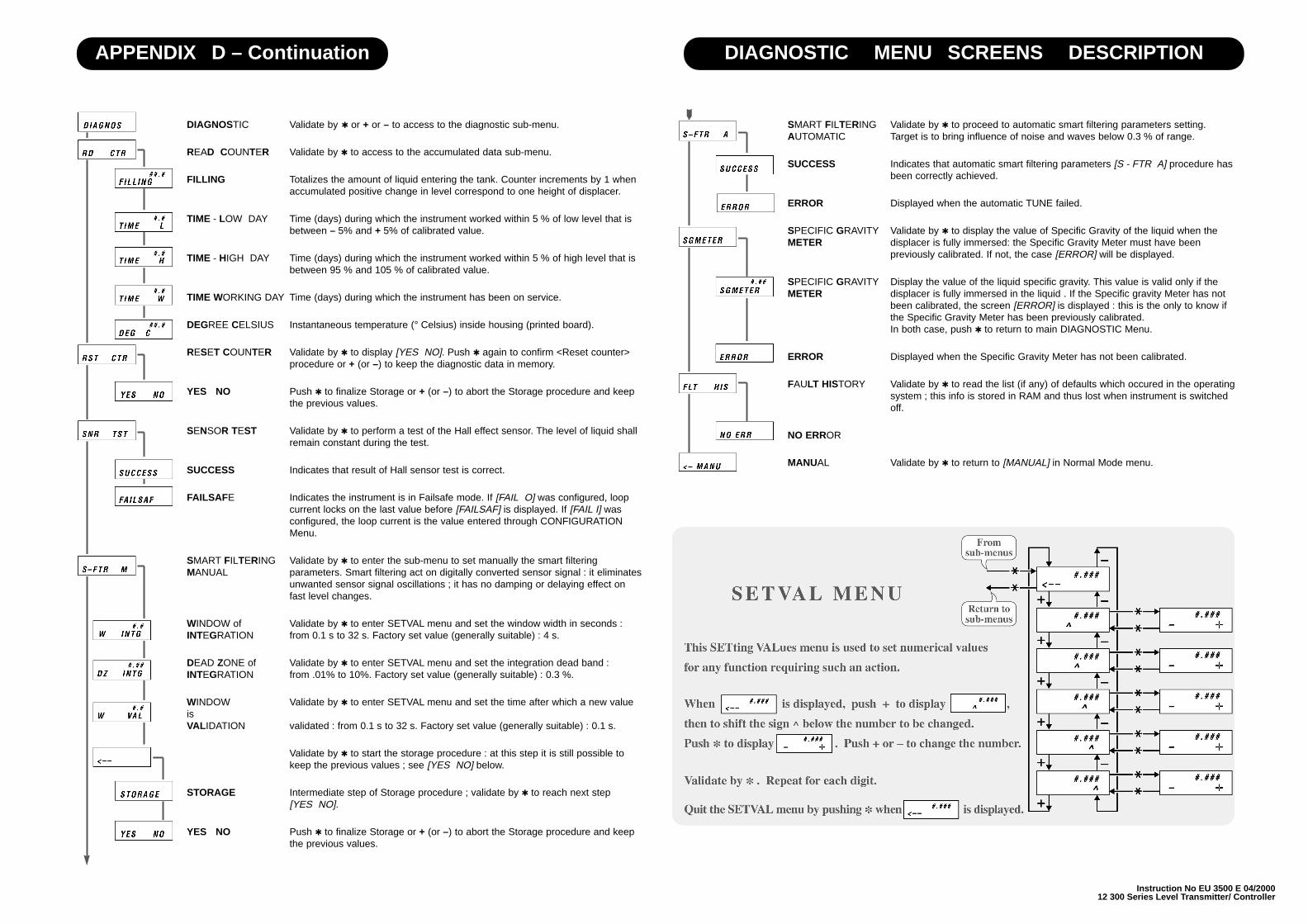
Instruction No EU 3500 E 04/200012 300 Series Level Transmitter/ Controller
SMART FILTERING Validate by to proceed to automatic smart filtering parameters setting. AUTOMATIC Target is to bring influence of noise and waves below 0.3 % of range.
SUCCESS Indicates that automatic smart filtering parameters [S - FTR A] procedure hasbeen correctly achieved.
ERROR Displayed when the automatic TUNE failed.
SPECIFIC GRAVITY Validate by to display the value of Specific Gravity of the liquid when the METER displacer is fully immersed: the Specific Gravity Meter must have been
previously calibrated. If not, the case [ERROR] will be displayed.
SPECIFIC GRAVITY Display the value of the liquid specific gravity. This value is valid only if the METER displacer is fully immersed in the liquid . If the Specific gravity Meter has not
been calibrated, the screen [ERROR] is displayed : this is the only to know ifthe Specific Gravity Meter has been previously calibrated. In both case, push to return to main DIAGNOSTIC Menu.
ERROR Displayed when the Specific Gravity Meter has not been calibrated.
FAULT HISTORY Validate by to read the list (if any) of defaults which occured in the operatingsystem ; this info is stored in RAM and thus lost when instrument is switchedoff.
NO ERROR
MANUAL Validate by to return to [MANUAL] in Normal Mode menu.
DIAGNOSTIC Validate by or + or – to access to the diagnostic sub-menu.
READ COUNTER Validate by to access to the accumulated data sub-menu.
FILLING Totalizes the amount of liquid entering the tank. Counter increments by 1 whenaccumulated positive change in level correspond to one height of displacer.
TIME - LOW DAY Time (days) during which the instrument worked within 5 % of low level that isbetween – 5% and + 5% of calibrated value.
TIME - HIGH DAY Time (days) during which the instrument worked within 5 % of high level that isbetween 95 % and 105 % of calibrated value.
TIME WORKING DAY Time (days) during which the instrument has been on service.
DEGREE CELSIUS Instantaneous temperature (° Celsius) inside housing (printed board).
RESET COUNTER Validate by to display [YES NO]. Push again to confirm <Reset counter>procedure or + (or –) to keep the diagnostic data in memory.
YES NO Push to finalize Storage or + (or –) to abort the Storage procedure and keep the previous values.
SENSOR TEST Validate by to perform a test of the Hall effect sensor. The level of liquid shallremain constant during the test.
SUCCESS Indicates that result of Hall sensor test is correct.
FAILSAFE Indicates the instrument is in Failsafe mode. If [FAIL O] was configured, loopcurrent locks on the last value before [FAILSAF] is displayed. If [FAIL I] wasconfigured, the loop current is the value entered through CONFIGURATIONMenu.
SMART FILTERING Validate by to enter the sub-menu to set manually the smart filtering MANUAL parameters. Smart filtering act on digitally converted sensor signal : it eliminates
unwanted sensor signal oscillations ; it has no damping or delaying effect onfast level changes.
WINDOW of Validate by to enter SETVAL menu and set the window width in seconds : INTEGRATION from 0.1 s to 32 s. Factory set value (generally suitable) : 4 s.
DEAD ZONE of Validate by to enter SETVAL menu and set the integration dead band : INTEGRATION from .01% to 10%. Factory set value (generally suitable) : 0.3 %.
WINDOW Validate by to enter SETVAL menu and set the time after which a new valueis VALIDATION validated : from 0.1 s to 32 s. Factory set value (generally suitable) : 0.1 s.
Validate by to start the storage procedure : at this step it is still possible tokeep the previous values ; see [YES NO] below.
STORAGE Intermediate step of Storage procedure ; validate by to reach next step[YES NO].
YES NO Push to finalize Storage or + (or –) to abort the Storage procedure and keep the previous values.
DIAGNOSTIC MENU SCREENS DESCRIPTIONAPPENDIX D – Continuation

Instruction No EU 3500 E 04/200012 300 Series Level Transmitter/ Controller
Now, proceed as indicated under Calibration :
Conditions to Calibration on Site in aLiquidThe effective change in level will be obtainedby emptying and fi l l ing of the displacerchamber with a liquid.
Wait that the displacer is stabilized to validatethe values displayed after each change inliquid level.
Take actions necessary to allow a change inthe liquid level in the chamber : open/closeisolation valves, vent, purge, etc.
Now, proceed as indicated under Calibration :
Calibration
1. Attach a set of weights to the torque arm tosimulate a low level or empty the displacerchamber. Switch on the power,
2. Enter the CALIBRATION Menu and press insequence : (or + or –), +, , , +, , todisplay [CALIBR],
3. Set the Specific Gravity value of the liquidused for calibration [SG CAL]. Refer toSection 5.1.4.8 for the SETVAL sub-menu,
4. Display [ZERO ] and press to takeaccount the REF L,NOTE : During the procedure, refer toSection 5.3.2.6 if the LCD displays[ERROR].
5. Attach a set of weights to the torque arm tosimulate a high level or fill the displacerchamber until the high level is reached,
6. Display [SPAN ] and press to takeaccount the REF H,
7. Move until [<– ] is displayed and press to store data via [STORAGE] and [YESNO] screens. [CAL Z S] is displayed,
8. Display successively [MA L], [MA H],[LEVEL L], [LEVEL H] and, if needed, setthe currents and levels corresponding toREF L and REF H,
9. Display [UNIT ] and define the unit for levelindication,
10.Move until [<– ] is displayed and press to store data via [STORAGE] and [YESNO] screens. [VAR SET] is displayed,
11.When the calibration is completed, moveinto the menu until [<–MANU] is displayed,then press to exit the CALIBRATIONMenu and to display [MANUAL],
12.Press , –, : [NORMAL] appears for afew seconds and the instrumentautomatically returns to Normal Operatingdisplay,
13.Reinstall the front plate (80) with the threescrews (125).
NOTE : The calibration specific gravity [SGCAL] is automatically stored in the servicespecific gravity function [SG SER]. If theinstrument is to be used with a liquid ofdifferent specif ic gravity, reenter theCALIBRATION Menu to set and accept thisnew value in [SG SER] to avoid the re-calibration. (See Section 5.3.2.3).
The purpose of this Section is to facilitate the firstcalibration and running in case of a level application ofthe instrument.
• Before installation, connection and start to running,carefully read Section 2. Protection Standard andSection 3. Installation.
• For explanations to general principles, the liquidcrystal display, the push buttons and how to use themenus, refer to Sections 5.1 and 5.1.1 to 5.1.3.
• For the menus description, refer to Section 5.1.4.
• To perform the instrument calibration proceed asfollows :
After the 12300 Level Transmitter has beeninstalled, remove the front plate (80) located infront of the instrument to gain access to the pushbuttons.
In NORMAL MODE (refer to APPENDIX A), theinstrument displays alternatively the loop currentand the level expressed in the unit (% orengineering unit) shown in the low left corner ofthe screen.
Stroking any of the button enters a sub-menuwhich allows to go to a MANUAL MODE where theinstrument can be configured, calibrated anddiagnosed :
NOTE : In the CONFIGURATION ANDCALIBRATION menus of APPENDIX B & C, thescreens which are only necessary for the firstoperation and simple calibration are highlighted bymeans of the white text on a colored background.
CONFIGURATION (Appendix B)To enter the CONFIGURATION Menu from theNormal operating mode, press in sequence : (or+ or –), +, , , , to display [CONFIG].
Select all required configuration data indicatedbellows :
• the instrument function (level or interface),
• the direction of head mounting (left or righttowards the displacer when facing the LCDwindow),
• the action (direct :current increases with level ;reverse : current decreases when levelincreases),
• the language of the display (english or french).
To quit the CONFIGURATION Menu and return toNormal Operating mode, move into the menu until[<–MANU] is displayed, then press to display[MANUAL], via [STORAGE ] and [YES NO].
Then press , –, : [NORMAL] appears for a fewseconds and the instrument automatically returnsto Normal Operating displaying alternatively thecurrent and the level.
CALIBRATION (Appendix C)
Conditions to Dry Calibration inWorkshop (Simulation by Weights)
Caution : When performing a calibration, usethe following parameter units wherever theyapply :
Parameter Name S.I Units English UnitsDisplacer Weight g lbmDisplacer Volume cm3 in3
Water Density (WD) 1 g/cm3 0.036 lbm/in3
The effective change in level will be simulatedby a set of weights corresponding to :
a) The weight of the actual displacer at lowlevel (REF L), which allows you to calibratethe zero and obtain the minimum value [0,0%] of the signal (direct action).
b) The apparent displacer weight when thelevel is high (REF H). This allows you tocalibrate the span and obtain the maximumvalue [100,0%] of the signal (direct action).The corresponding weight is calculated as :
Caution : Special displacer may be providedfor specific applications (material, serviceconditions…). In this case, volume and/orweight will differ from standard displacercharacteristics.
Actual volume and weight of the displacercan be read using HART function only ifthey have been previously stored in the DLThead. Otherwise, actual volume of thedisplacer is marked on the specificationplate (124).Weight the displacer to get the actualweight.
Apparent Displacer Weight =Displacer Actual Weight – (Displacer Actual Volume x S.G.x WD)
Danger : If area cannot be verified as safe, do notremove any covers.
APPENDIX E FIRST OPERATING AND SIMPLE CALIBRATION FOR A LEVEL INSTRUMENT SERVICE

Instruction No EU 3500 E 04/200012 300 Series Level Transmitter/ Controller
APPENDIX FSPECIFIC MODES
This annex describes two specific operating modes.1 Push button locking.
In MANUAL MODE, the use of push button can belocked by sending a specific HART message with the275 communicator (loaded with the relevant DDL).
This locking prevents any change in the menusCONFIGURATION, CALIBRATION and DIAGNOSTIC.
However, the MANUAL MODE can be unlocked when
using the password stored in the HDLT during the 275communicator locking operation. Th MANUAL MODEis automatically locked again when the user go back toNORMAL MODE. The MANUAL MODE unlockingthrough the push buttons is then temporary. Thesketch below indicates how unlocking the MANUALMODE with the pasword:
2 Controller mode.
When the CONTROLLER MODE is enabled in theCONFIGURATION menu:[CTRL I]; the NORMALMODE menu is displayed differently. Three data are
displayed alternatively: the liquid level, the loop currentand the controller set point. The following sketchindicates how to modify the controller setpoint:
Remarks :
- The controller set point can be modified even if thepush buttons are locked.
- The loop current doesn't indicate the liquid level butthe controller output (which is the valve position setpoint).
- The controller set point is always displayed by theLCD in level unit.
- If the set point and level units are different, the ratiocontrol is activated and you have to calculate andenter the good values of the Ratio gain and Ratiobias (see the 275 communicator instruction EU 3500HC E). A bad set point display is then avoided.
Instruction No EU 3500 HC E
04/2000
1 / 45
HDLT 12300HART
®
COMMUNICATION

HDLT COMMUNICATOR
2 / 45
This guide describes the device specific instructions for using the HART 275 Hand Held Communicatorwith the Masoneilan HDLT 12300 software revision 4.12 and 5.11 and HART Device Description Language (DDL)revision 65640102.ddl embelled in the Communicator 275.The following pages covers basic instruction for using the communicator. Refer to HART Communicatormanual MAN 4250 for more information.
The menus structure is a guide to performing all of the operations which are possible from the Hand HeldCommunicator to configure, calibrate and diagnose the HDLT 12300 serie.
TABLE of CONTENTS
Hart Communicator 275 using........................................................ 3Hart Communicator 275 connections ............................................ 5Hart Communicator 275 starting .................................................... 6Hart Communicator 275 functions ................................................. 8
HOME MENU .................................................................................. 10INFO MENU .................................................................................. 13HDLT RESET .................................................................................. 18
CONFIG MENUTAG .......................................................................... 20SETUP...................................................................... 22ALARMS................................................................... 24SET DATA BASE ..................................................... 26CTRL PARAMETERS .............................................. 29
CALIBRATE MENUTOOLS ..................................................................... 32CALIBRATION
TRANSMITTER......................................... 34S.G. METER.............................................. 36
PARAMETERS......................................................... 38
DIAGNOSTIC MENUDIAGNOSTIC DATA................................................. 40RESET CONTINUOUS............................................. 40SENSOR TEST ........................................................ 40SMART FILTERING ................................................. 40SG METER ............................................................... 40FAULT HISTORIC.................................................... 40
CONTROLLER MENUCONTROLLER VIEW............................................... 42PID SETTING ........................................................... 42SETPOINT................................................................ 42
Principle of calibration .................................................................. 44
Trademark information.................................................................. 45

HDLT COMMUNICATOR
3 / 45
HART COMMUNICATOR USINGThe table below is limited to basic information for using the HART Communicator with theHDLT 12300.See the HART ref MAN 4250 for more information.
Use this key to turn the Communicator ON or OFF. Whenthe communicator is turned on, it searches for a HART compatibledevice in the 4-20mA loop.If nothing is found, the message displayedis : »No device found.Press OK ».
UP ARROW KEY :Use this key to move the cursor → up through a menu or a list ofoptions.
DOWN ARROW KEY :Use this key to move the cursor → down through a menu or a list ofoptions.
LEFT ARROW AND PREVIOUS MENU KEY :Use this dual function key to move the cursor to the left or to comeback to the previous menu.
RIGHT ARROW AND SELECT KEY :Use this dual function key to move the cursor to the right or to selectbrightness option.
HOT KEY :Use this key to quickly access important menu or optionswhen the communicator is connected to the HDLT.If the communicator is OFF , pressing on this key turn ONthe communicator and displays the INFO menu 5.See the MAN 4250 to customizing the HOT KEY MENU.
Four defined function keys marked F1 to F4 perform action in the different menus regarding the labelappearing above these key. Below are some currently label diplayed. See MAN 4250 for all label information.
HELP access the one line help for the function or the variable diplayed.EXIT to leave the current menu.YES to answer a question.RETRY to try to re-establish the HART communication.ON to select an option.OFF to suppress an option.DEL to delete current character during edition.PGUP to move up one help screen.ABORT to stop current task.HOME to go to the top menu.PGDN to move down one help screen.OK to acknowledge information on the screen.ENTER to accept information on the screen and to display next screen.NO to answer a question.
F1
HDLT:TRS1** NORMAL MODE** 1 LEVEL 7.0 in 2 PERCENT 50.0 % 3 CURRENT 12.000 mA 4 TO MANUAL MODE ↓ 5 INFO
HELP SAVE
←←←←
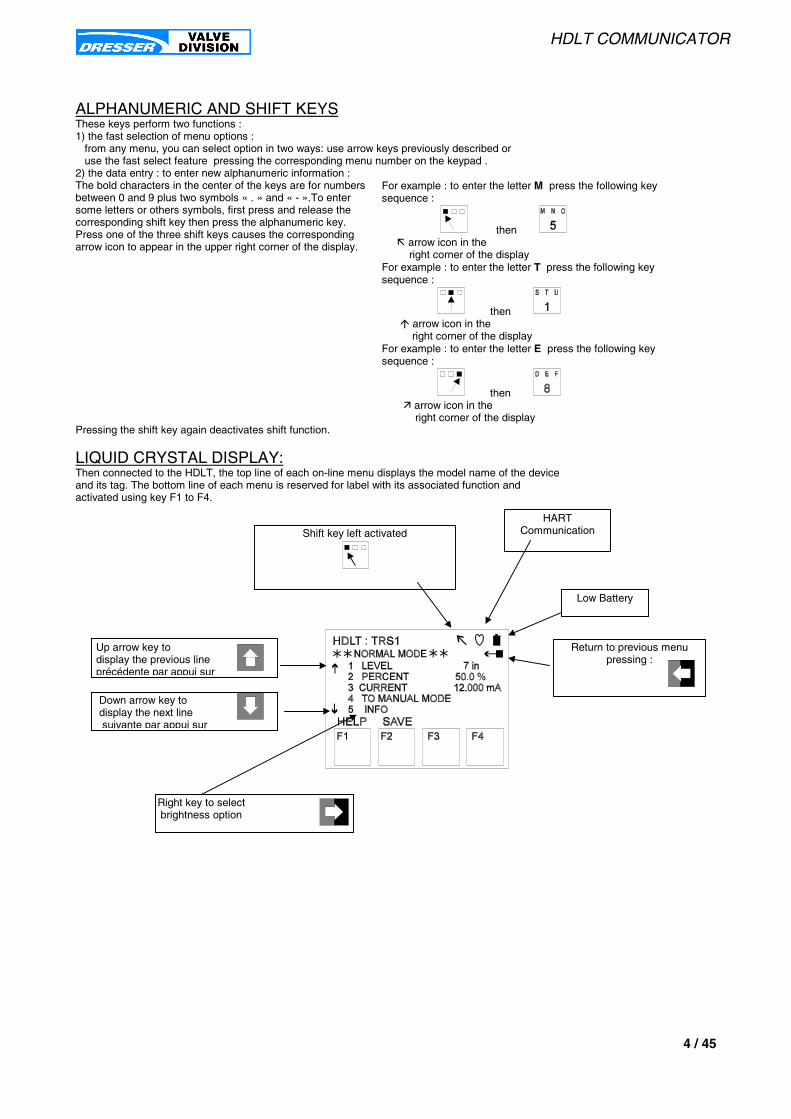
HDLT COMMUNICATOR
4 / 45
ALPHANUMERIC AND SHIFT KEYSThese keys perform two functions :1) the fast selection of menu options : from any menu, you can select option in two ways: use arrow keys previously described or use the fast select feature pressing the corresponding menu number on the keypad .2) the data entry : to enter new alphanumeric information :The bold characters in the center of the keys are for numbersbetween 0 and 9 plus two symbols « . » and « - ».To entersome letters or others symbols, first press and release thecorresponding shift key then press the alphanumeric key.Press one of the three shift keys causes the correspondingarrow icon to appear in the upper right corner of the display.
For example : to enter the letter M press the following keysequence :
then ! arrow icon in the right corner of the displayFor example : to enter the letter T press the following keysequence :
then " arrow icon in the right corner of the displayFor example : to enter the letter E press the following keysequence :
then # arrow icon in the right corner of the display
Pressing the shift key again deactivates shift function.
LIQUID CRYSTAL DISPLAY:Then connected to the HDLT, the top line of each on-line menu displays the model name of the deviceand its tag. The bottom line of each menu is reserved for label with its associated function andactivated using key F1 to F4.
Shift key left activatedHART
Communication
Low Battery
Return to previous menupressing :
Up arrow key to display the previous lineprécédente par appui sur
Down arrow key to display the next line suivante par appui sur
Right key to select brightness option

HDLT COMMUNICATOR
5 / 45
HART COMMUNICATOR CONNECTIONS
WARNING : Before connecting the HART Communicator in an explosive atmosphere,make sure the devices in the loop are installed in accordance with intrinsically safe ornonincendive field wiring practices. For more information see the HART Communicatormanual: MAN 4250.In addition for explosion proof or flame proof area, a connection on the site through theterminal board is absolutly forbidden.
The HART Communicator can be connected to the HDLT transmitter from different locations:in the control room,
on the site through the terminal board on the HDLT heador any wiring termination in the loop.
In any case , connect the HART Communicator in parallel with the instrument or a load resistor in the loop.The connection are not polarized. For the HART Communicator to function properly, a minimum of 110 ohmsresistance must be present in the loop. See below the wiring connections for non explosive atmosphere.
RL >=250 Ω
- +
H H
POWERSUPPLY
-
+
HDLT 12300
FIGURE 1. HART Communicator connected on the HDLT or on the loop termination.
RL >=250 Ω
- +
H H
POWERSUPPLY
-
+
HDLT 12300
FIGURE 2. HART Communicator connected across a load resistor.
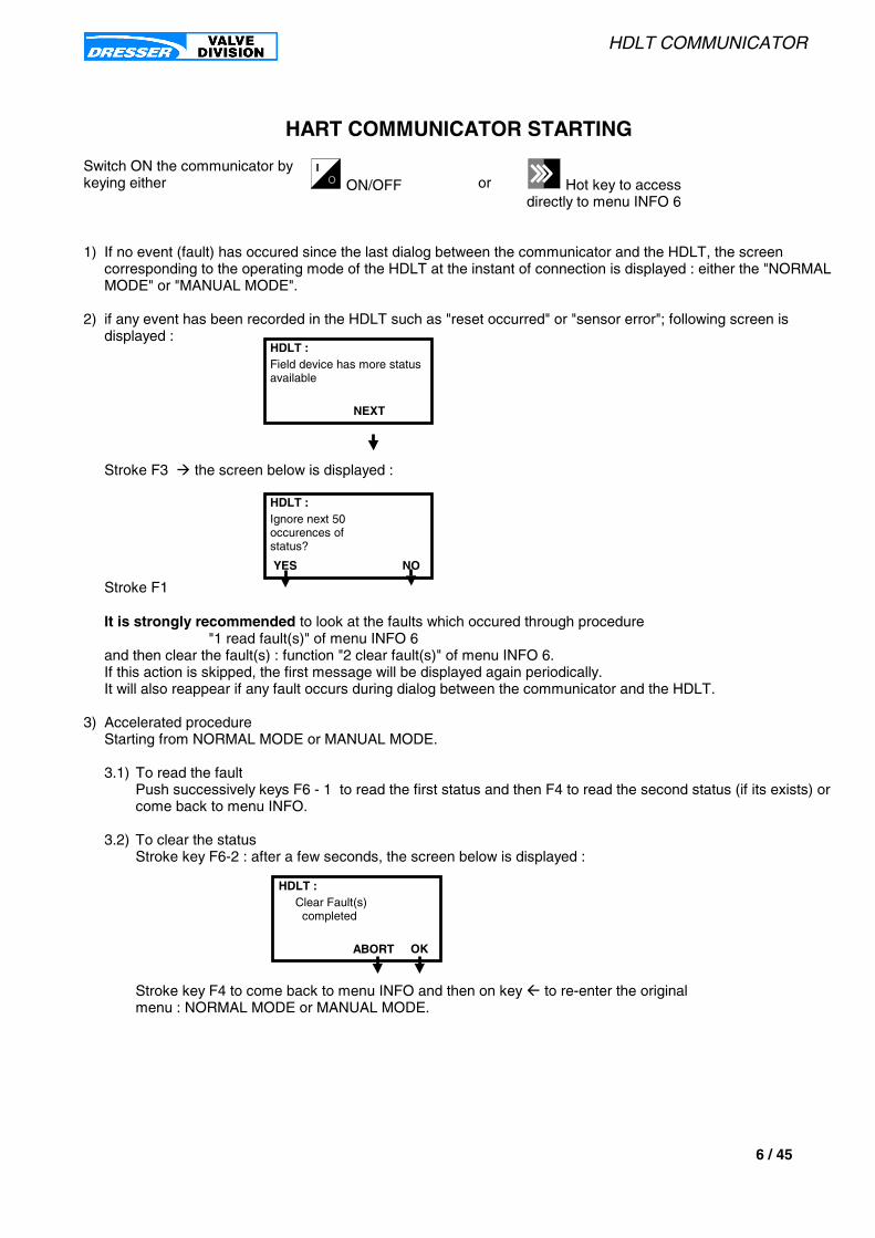
HDLT COMMUNICATOR
6 / 45
HART COMMUNICATOR STARTING
Switch ON the communicator bykeying either ON/OFF or Hot key to access
directly to menu INFO 6
1) If no event (fault) has occured since the last dialog between the communicator and the HDLT, the screencorresponding to the operating mode of the HDLT at the instant of connection is displayed : either the "NORMALMODE" or "MANUAL MODE".
2) if any event has been recorded in the HDLT such as "reset occurred" or "sensor error"; following screen isdisplayed :
Stroke F3 $ the screen below is displayed :
Stroke F1
It is strongly recommended to look at the faults which occured through procedure"1 read fault(s)" of menu INFO 6
and then clear the fault(s) : function "2 clear fault(s)" of menu INFO 6.If this action is skipped, the first message will be displayed again periodically.It will also reappear if any fault occurs during dialog between the communicator and the HDLT.
3) Accelerated procedureStarting from NORMAL MODE or MANUAL MODE.
3.1) To read the faultPush successively keys F6 - 1 to read the first status and then F4 to read the second status (if its exists) orcome back to menu INFO.
3.2) To clear the statusStroke key F6-2 : after a few seconds, the screen below is displayed :
Stroke key F4 to come back to menu INFO and then on key % to re-enter the originalmenu : NORMAL MODE or MANUAL MODE.
NEXT
Field device has more statusavailable
HDLT :
YES NO
Ignore next 50occurences ofstatus?
HDLT :
ABORT OK
Clear Fault(s) completed
HDLT :

HDLT COMMUNICATOR
7 / 45
NOTES

HDLT COMMUNICATOR
8 / 45
HART COMMUNICATOR 275 - FUNCTIONS
COMMUNICATOR 275 FUNCTIONS
Offline See communicator manual.
Online Run the communication procedure between the HDLT transmitter and the communicator.If any fault(s) or event(s) have been recorded by the transmitter, the first message displayed is: « Field device has more status available ». See STARTING document to know the procedure.
Frequency Device See communicator manual.
Utility See communicator manual.

HDLT COMMUNICATOR
9 / 45
HART Communicator
1 Offline2 Online3 Frequency Device4 Utility
0
Standard HHT function. InOFFLINE menu, the customercan configured and store in theHHT memory:
tagdescriptormessagefinal assembly nbrdatepolling address
Standard HHT functions
See HHT manual
COMMUNICATOR 275 - FUNCTIONS
SAVE
Hot key menu :1 INFO
HDLT :
6

HDLT COMMUNICATOR
10 / 45
HOME MENU
NORMAL MODE1 level : indicate the actual level of liquid in % or in other engineering units
2 perc : indicate the percentage of current in the loop.This value is based on the low and highcurrent values set .
3 current : Output signal and current loop in mA.
4 TO MANUAL MODE
To go to MANUAL MODE
5 CONTROLLER MENU
If controller mode actived on the HDLT, this function allows to display controller parameters,to change the PID parameters and to modify the controller setpoint.
6 INFO : Transmitter information: configuration, calibration, diagnostic data, data base, HART identification parameters , faults resume and clear faults.
7 HDLT reset : This function perform a master reset to the device, causing it to go through its startup routine andre-initializing all of its operating parameters from non volatile memory.
OR
MANUAL MODE1 level : indicate the actual level of liquid in % or in other engineering units
2 perc : indicate the percentage of current in the loop.This value is based on the low and highcurrent values set .
3 manual output: To control in manual the controller output.The user can set a current loop in mA.The following information is displayed to inform the user of special state of the transmitteroutput: " Analog output 1 and its digital representation are in fixed mode and not responsive to input changes ".
4 MANUAL MODE MENU
To display the MANUAL MODE MENU.
5 CONTROLLER MENU
If controller mode is actived on the HDLT, this function allows to display controller parameters,to change the PID parameters and to modify the controller setpoint.
6 INFO : Transmitter information: configuration, calibration, diagnostic data, data base, HART identification parameters , faults resume and clear faults.
7 HDLT reset : This function perform a master reset to the device, causing it to go through its startup routine andre-initializing all of its operating parameters from non volatile memory.
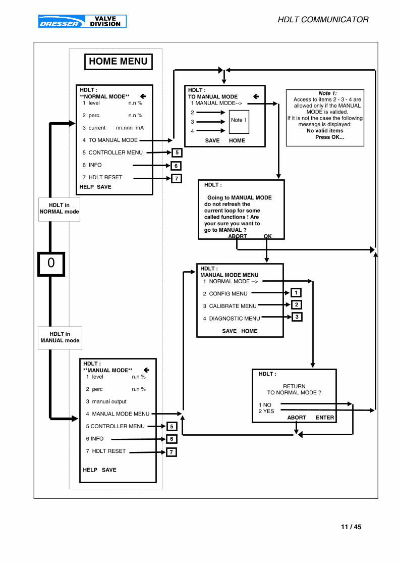
HDLT COMMUNICATOR
11 / 45
HDLT :**MANUAL MODE** &&&&1 level n.n %
2 perc n.n %
3 manual output
4 MANUAL MODE MENU
5 CONTROLLER MENU
6 INFO
7 HDLT RESET
HELP SAVE
HDLT :MANUAL MODE MENU1 NORMAL MODE -->
2 CONFIG MENU
3 CALIBRATE MENU
4 DIAGNOSTIC MENU
SAVE HOME
3
2
1
0
HDLT inNORMAL mode
HDLT inMANUAL mode
HDLT :**NORMAL MODE** &&&&1 level n.n %
2 perc. n.n %
3 current nn.nnn mA
4 TO MANUAL MODE
5 CONTROLLER MENU
6 INFO
7 HDLT RESET
HELP SAVE
Note 1:Access to items 2 - 3 - 4 areallowed only if the MANUAL
MODE is valided.If it is not the case the following
message is displayed:No valid items
Press OK...
HDLT :
Going to MANUAL MODEdo not refresh thecurrent loop for somecalled functions ! Areyour sure you want to
go to MANUAL ?ABORT OK
HDLT :
RETURNTO NORMAL MODE ?
1 NO2 YES
ABORT ENTER
HOME MENU
5
7
HDLT :TO MANUAL MODE &&&&1 MANUAL MODE-->
2
3
4
SAVE HOME
Note 1
6
6
7
5

HDLT COMMUNICATOR
12 / 45

HDLT COMMUNICATOR
13 / 45
INFO MENU
MENU 61 read fault(s) Read fault(s) recorded by the HDLT during any bad user configuration, calibration or hardware fault on the electronic module.
2 clear fault(s) To clear all fault(s) recorded by the HDLT during any bad user configuration, calibration or hardware faulton the electronic module.
3 read identifierTag Tag- Text that is associated with the Field Device installation. This text can be used by the user in any way. A recommended
use is as a unique label to a plant that correlates to a Field Device label : a plant drawing, or on a Control System. This variableis also used as a type of data link layer address handle.
Descriptor Descriptor- Text that is associated with the Field Device installation. This text can be used by the user in any way. There is nospecific recommended use.
Message Message- Text that is associated with the Field Device. This text can be used by the user in any way. There is no recommendeduse.
Final asmbly num Final Assembly Number- Number that is used for identification purposes, and is associated with the overall Field Device.
Date Date- Gregorian calendar date that is stored in the Field Device. This can be used by the user in any way. There is no specificrecommended use.Enter MM/DD/YYYY.
Poll addr Polling Address- Adress used by the Host to identify a Field Device, and changeable by the User to control the MultidropMode.
Manufacturer Manufacturer Identification Code- Références a specific manufacturer, which is usually a company name, that is responsiblefor the manufacture of this Field Device.
Model Model- Références the type of field Device, usually an advertised mode number, that is unique to a singlemanufacturer.
Device id Field Device Identification- Uniquely identifies the Field Device when combined with the Manufacturer Identification andDevice Type. Therefore, this variable cannot be modified by the Host user.
Universal cmd rev Universal Command Revision- Revision of the Universal Device Description, that the Field Device conforms to.
Transmit cmd rev Field Device Revision- Revision of the Field Device Specific Device Description, that the Field Device conforms to.
Software rev Field Device Software Revision- This revision corresponds to the software or firmware, that is embedded in the Field Device.
Hardware rev Hardware Revision- Revision that corresponds to the electronics hardware of the Field Device.
Physicl signl code Physical Signaling Code- the Physical Signaling Code describes the type of Physical Layer that has been implemented in thehardware that is responsible for the HART Communication port.
Device flags Field Device Flags- Describes special features of the Field Device that affect the Data Link Layer.
Num resp preams Number of Request Preambles- Number of Preambles required from the Host request by the Field Device.
4 level configsetup HDLT configuration information ( current acting, mounting ...)
buttons Lock level for push buttons to avoid unintended modifications.
alarms Status and limits for low/high level alarms and fail mode.
language Choice of different languages displayed on the HDLT LCD.

HDLT COMMUNICATOR
14 / 45
5 level calibrationdamping Output current filtering. Value expressed in second and corresponding to T63% for first order response step.
low signal Low output current for low level (direct acting) or low output current for high level (reverse acting).Must be between 3.8 mA and 14 mA.
high signal High output current for high level (direct acting) or high output current for low level (reverse acting).Must be between 8 mA and 20.5 mA.
low level Value in engineering units for low level and corresponding to zero calibration.
high level Value in engineering units for high level and corresponding to span calibration.
zero shift Value in percentage of calibration scale (zero/span) to shift the ZERO in an other position. The current output isautomatically re-ajusted on this new ZERO position.
reduce span Value in percentage of calibration scale (zero/span) to reduce the SPAN . The current output isautomatically re-ajusted to take into account this new SPAN.
SG CAL Specific gravity specified during the calibration procedure and corresponding to the liquid specific gravity in the chamberor the simulation by weight.This specific gravity is used only in LEVEL transmitter.
SF SER This specific gravity is normally the same as the specific gravity of calibration but need to be change if the liquid specificgravityof the process is not the same as which one used during the transmitter calibration.This specific gravity is used only in LEVEL transmitter.
SG Lower CAL Specific gravity specified during the calibration procedure and corresponding to the LOWER liquid specific gravity in thechamberor the simulation by weight.This specific gravity is used only in INTERFACE transmitter.
SG Upper CAL Specific gravity specified during the calibration procedure and corresponding to the UPPER liquid specific gravity in thechamberor the simulation by weight.This specific gravity is used only in INTERFACE transmitter.
SG Lower SER This specific gravity is normally the same as the LOWER specific gravity of calibration but need to be changethe LOWER liquid specific gravity of the process is not the same as which one used during the transmitter calibration.This specific gravity is used only in INTERFACE transmitter.
SG Upper SER This specific gravity is normally the same as the UPPER specific gravity of calibration but need to be change ifthe UPPER liquid specific gravity of the process is not the same as which one used during the transmitter calibration.This specific gravity is used only in INTERFACE transmitter.
SGM SG CAL Specific gravity of calibration for the specific gravity meter.
hall temp cal Temperature in Celcius for the elctronic head during the ZERO and SPAN calibration.
6 diagnostic datanbr of filling up Total number of filling tanks.
time tank empty Time in days for tank empty.
time tank full Time in days for tank full .
time working Time in days for HDLT working.
head temperature Indicate the internal temperature inside the HDLT head.
7 Data basedisplacer volume Value in liter or cubic inchdisplacer weight Value in gr, kg, pound.displacer height Value in in or mm.displacer diameter Value in in or mm.displacer options special material , rod extension ....
chamber type list of all configuration.chamber options Special design and material.
torque tube Material used for the torque tube and the torque tube chamber.force Mecanical parameter for the torque tube.
arm lenght arm lenght between the torque tube and the displacer in inches
general options Torque tube extension for high or low process temperature and specification for use in dangerous area.

HDLT COMMUNICATOR
15 / 45
6
MENU 6
HDLT :INFO &&&&1 read fault(s) *2 clear fault(s) *3 read identifier4 level config5 level calibration6 diagnostic data7 data base8 controller config.9 controller PID burst mode
SAVE HOME
HDLT :read identifier &&&&1 Tag2 Descriptor3 Message4 Final asmbly num5 Date nn/nn/nn6 poll addr7 Manufacturer8 Model HDLT9 Device id nnnnn
Universalcmd revTransmit cmd rev
nSoftware rev nHardware rev nPhysicl signl codeDevice flagsNum resp preams n
HELP SEND HOME
HDLT :diagnostic data &&&&1 nbr of filling up2 time tank empty3 time tank full4 time working5 head temperature
HELP SAVE HOME
HDLT :level config &&&&1 setup2 buttons3 alarms4 language xxxx
HELP SEND HOME
HDLT :level calibration &&&&1 damping n.n s2 low signal n.n mA3 high signal n.n mA4 low level n.n unit5 high level n.n unit6 zero shift n.n %7 reduce span n.n %8 SG CAL n.n **9 SG SER n.n ** SGM SG CAL n.n hall temp cal n.n °C
HELP SEND
HDLT :data base &&&&1 displacer volume2 displacer weight3 displacer height4 displacer diameter5 displacer options6 chamber type7 chamber options8 torque tube9 force arm lenght general options
HELP SAVE HOME
* :Read fault(s) means :Display events or faults thathave occured since the last"Clear fault(s)".Clear fault(s) :Reset all fault(s).
** :In Level : SG CAL n.nnn SG SER n.nnnIN Interface :SG Lower CAL n.nnnSG Upper CAL n.nnnSG Lower SER n.nnnSG Upper SER n.nnn
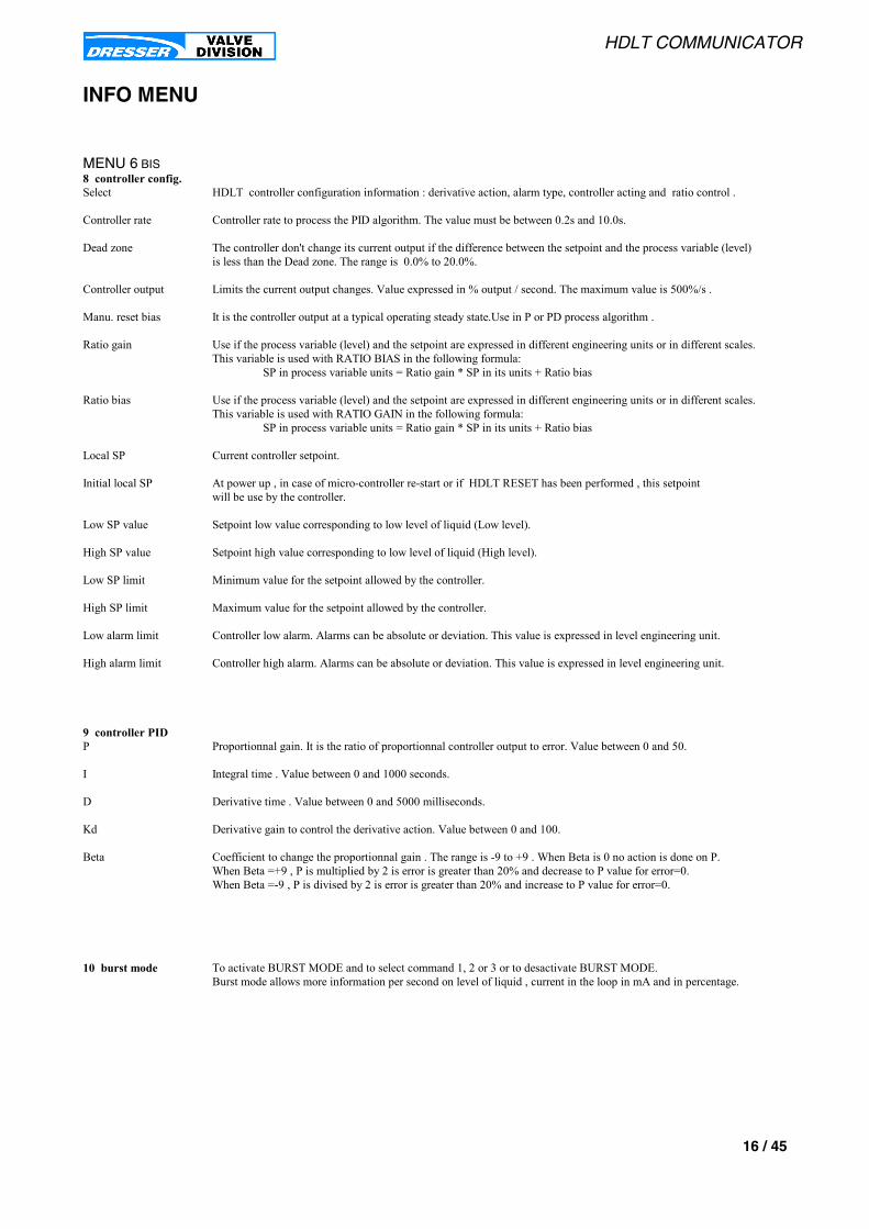
HDLT COMMUNICATOR
16 / 45
INFO MENU
MENU 6 BIS8 controller config.Select HDLT controller configuration information : derivative action, alarm type, controller acting and ratio control .
Controller rate Controller rate to process the PID algorithm. The value must be between 0.2s and 10.0s.
Dead zone The controller don't change its current output if the difference between the setpoint and the process variable (level)is less than the Dead zone. The range is 0.0% to 20.0%.
Controller output Limits the current output changes. Value expressed in % output / second. The maximum value is 500%/s .
Manu. reset bias It is the controller output at a typical operating steady state.Use in P or PD process algorithm .
Ratio gain Use if the process variable (level) and the setpoint are expressed in different engineering units or in different scales.This variable is used with RATIO BIAS in the following formula: SP in process variable units = Ratio gain * SP in its units + Ratio bias
Ratio bias Use if the process variable (level) and the setpoint are expressed in different engineering units or in different scales.This variable is used with RATIO GAIN in the following formula: SP in process variable units = Ratio gain * SP in its units + Ratio bias
Local SP Current controller setpoint.
Initial local SP At power up , in case of micro-controller re-start or if HDLT RESET has been performed , this setpointwill be use by the controller.
Low SP value Setpoint low value corresponding to low level of liquid (Low level).
High SP value Setpoint high value corresponding to low level of liquid (High level).
Low SP limit Minimum value for the setpoint allowed by the controller.
High SP limit Maximum value for the setpoint allowed by the controller.
Low alarm limit Controller low alarm. Alarms can be absolute or deviation. This value is expressed in level engineering unit.
High alarm limit Controller high alarm. Alarms can be absolute or deviation. This value is expressed in level engineering unit.
9 controller PIDP Proportionnal gain. It is the ratio of proportionnal controller output to error. Value between 0 and 50.
I Integral time . Value between 0 and 1000 seconds.
D Derivative time . Value between 0 and 5000 milliseconds.
Kd Derivative gain to control the derivative action. Value between 0 and 100.
Beta Coefficient to change the proportionnal gain . The range is -9 to +9 . When Beta is 0 no action is done on P.When Beta =+9 , P is multiplied by 2 is error is greater than 20% and decrease to P value for error=0.When Beta =-9 , P is divised by 2 is error is greater than 20% and increase to P value for error=0.
10 burst mode To activate BURST MODE and to select command 1, 2 or 3 or to desactivate BURST MODE.Burst mode allows more information per second on level of liquid , current in the loop in mA and in percentage.

HDLT COMMUNICATOR
17 / 45
6
MENU 6 BIS
HDLT :INFO &&&&1 read fault(s) *2 clear fault(s) *3 read identifier4 level config5 level calibration6 diagnostic data7 data base8 controller config.9 controller PID burst mode
SAVE HOME
HDLT :controller config. &&&&1 Select2 Controller rate3 Dead zone4 Controller output5 Manu. reset bias6 Ratio gain7 Ratio bias8 Local SP9 Initial local SP
Low SP valueHigh SP valueLow SP limitHigh SP limitLow alarm limitHigh alarm limit
HELP SAVE HOME
HDLT :controller PID &&&&1 P2 I3 D4 Kd5 BetaHELP SAVE HOME
HDLT :Command number :
xxxxxxPV% range - currentProcess Vars-current
HELP ABORT ENTER
HDLT :Burst mode control :
xxxxxOffOn
ABORT ENTER

HDLT COMMUNICATOR
18 / 45
HDLT RESET
MENU 7HDLT RESET This function performs a master reset to the device, causing it to go through its startup
routine and re-initializing all of its operating parameters from non volatile memory.
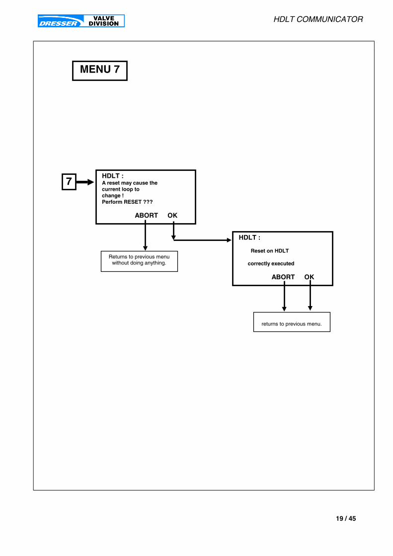
HDLT COMMUNICATOR
19 / 45
MENU 7
HDLT :A reset may cause thecurrent loop tochange !Perform RESET ???
ABORT OK
7
returns to previous menu.
Returns to previous menuwithout doing anything.
HDLT :
Reset on HDLT
correctly executed
ABORT OK
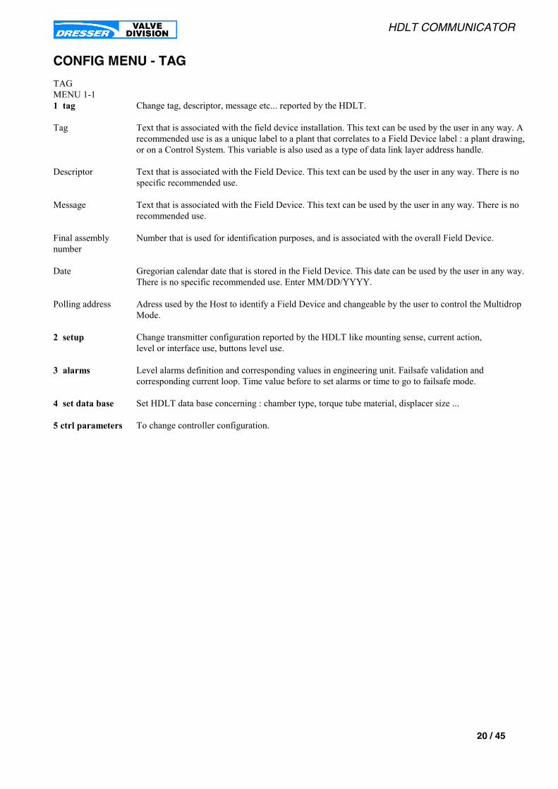
HDLT COMMUNICATOR
20 / 45
CONFIG MENU - TAG
TAGMENU 1-11 tag Change tag, descriptor, message etc... reported by the HDLT.
Tag Text that is associated with the field device installation. This text can be used by the user in any way. Arecommended use is as a unique label to a plant that correlates to a Field Device label : a plant drawing,or on a Control System. This variable is also used as a type of data link layer address handle.
Descriptor Text that is associated with the Field Device. This text can be used by the user in any way. There is nospecific recommended use.
Message Text that is associated with the Field Device. This text can be used by the user in any way. There is norecommended use.
Final assemblynumber
Number that is used for identification purposes, and is associated with the overall Field Device.
Date Gregorian calendar date that is stored in the Field Device. This date can be used by the user in any way.There is no specific recommended use. Enter MM/DD/YYYY.
Polling address Adress used by the Host to identify a Field Device and changeable by the user to control the MultidropMode.
2 setup Change transmitter configuration reported by the HDLT like mounting sense, current action,level or interface use, buttons level use.
3 alarms Level alarms definition and corresponding values in engineering unit. Failsafe validation andcorresponding current loop. Time value before to set alarms or time to go to failsafe mode.
4 set data base Set HDLT data base concerning : chamber type, torque tube material, displacer size ...
5 ctrl parameters To change controller configuration.
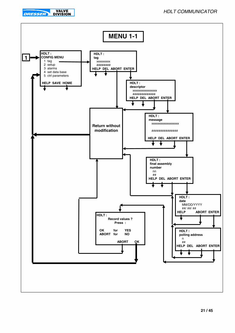
HDLT COMMUNICATOR
21 / 45
1HDLT :CONFIG MENU
1 tag2 setup3 alarms4 set data base5 ctrl parameters
HELP SAVE HOME
MENU 1-1
HDLT :tag
xxxxxxxxx########
HELP DEL ABORT ENTER
HDLT :descriptor
xxxxxxxxxxxxxxxx#############
HELP DEL ABORT ENTER
Return withoutmodification
HDLT :final assemblynumber
nn##
HELP DEL ABORT ENTER
HDLT :Record values ?
Press :
OK for YESABORT for NO
ABORT OK
HDLT :date
MM/DD/YYYY##/ ##/ ##
HELP ABORT ENTER
HDLT :polling address
n##
HELP DEL ABORT ENTER
HDLT :message
xxxxxxxxxxxxxxxxxx
###############
HELP DEL ABORT ENTER

HDLT COMMUNICATOR
22 / 45
CONFIG MENU - SETUP
SETUPMENU 1-21 tag Change tag, descriptor, message etc... reported by the HDLT.
2 setup Change transmitter configuration reported by the HDLT : mounting sense, current action,level or interface use, buttons level use and controller activation.
interface OFF = transmitter used in level indicator.ON = transmitter used in liquid interface indicator.
right OFF = left mounting. See instruction manual for more information .ON = right mounting. See instruction manual for more information .
reverse acting OFF = direct acting : an increase in level of liquid induces an increase of the loop current .ON = the loop current decreases when the level of liquid increases.
controller OFF = controller not activedON= controller actived. This is allowed only if the transmitter implement this function.
Display language Possibility of different languages displayed on the HDLT LCD.English : All screens are diplayed in English language.French : All screens are diplayed in French language.
Buttons : lock level Define use level: OFF is no restriction. All menus are available. ON is limited use to INFO MENU in NORMAL MODE.
Password If the buttons are in locked position, the user can unlock them entering a password.This password is a number between 1 to 255 with odd parity.This function is not available on firmware 4.12 embelled in the HDLT.
3 alarms Level alarms definition and corresponding values in engineering unit. Failsafe validation andcorresponding current loop. Time value before to set alarms or time to go to failsafe mode.
4 set data base Set HDLT data base concerning : chamber type, torque tube material, displacer size ...
5 ctrl parameters To change controller configuration.
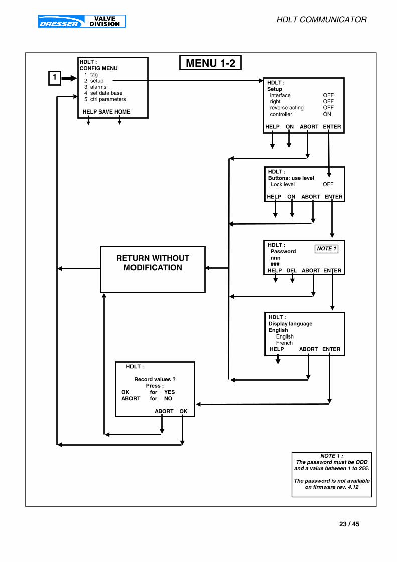
HDLT COMMUNICATOR
23 / 45
HDLT :Setupinterface OFFright OFFreverse acting OFFcontroller ON
HELP ON ABORT ENTER
1
HDLT :CONFIG MENU
1 tag2 setup3 alarms4 set data base5 ctrl parameters
HELP SAVE HOME
HDLT :Buttons: use levelLock level OFF
HELP ON ABORT ENTER
HDLT :Display languageEnglish
EnglishFrench
HELP ABORT ENTER
RETURN WITHOUTMODIFICATION
HDLT :
Record values ?Press :
OK for YESABORT for NO
ABORT OK
MENU 1-2
HDLT :Passwordnnn###
HELP DEL ABORT ENTER
NOTE 1
NOTE 1 :The password must be ODD
and a value between 1 to 255.
The password is not availableon firmware rev. 4.12
HDLT COMMUNICATOR
24 / 45
CONFIG MENU - ALARMS
ALARMSMENU 1-31 tag Change tag, descriptor, message etc... reported by the HDLT.
2 setup Change transmitter configuration reported by the HDLT like mounting sense, current action,level or interface use, buttons level use.
3 alarms Level alarms definition and corresponding values in engineering unit. Failsafe validation andcorresponding current loop. Time value before to set alarms or time to go to failsafe mode.
FAIL OFF = in case the instrument must go to failsafe mode the loop current will be: frozen to the last current value if FAIL = OFF, set to a specified current value if FAIL = ON.
LOW ALARM OFF = not low alarm setON = low alarm is activated and will be set if Time1 is >0 . If Time 2 is also >0 , the transmitter will be force to faisafe mode after Time 2 elapsed.
HIGH ALARM OFF = not high alarm setON = high alarm is activated and will be set if Time1 is >0 . If Time 2 is also >0 , the transmitter will be force to faisafe mode after Time 2 elapsed.
fail current Displayed only if FAIL=ON.Current value for failsafe mode. This value must be between 3.6mA and 23.0mA.
Low alarm level Displayed only if LOW ALARM=ON.Alarm threshold in the same engineering units as the level of liquid corresponding to the level valueunder which the transmitter set a low alarm or go to failsafe mode regarding Time 1 and Time 2.
High alarm level Displayed only if HIGH ALARM=ON.Alarm threshold in the same engineering units as the level of liquid corresponding to the level valueabove which the transmitter set a high alarm or go to failsafe mode regarding Time 1 and Time 2.
Time 1 Time duration is seconds which will elapse between the moment the level goes higher thanHigh alarm level (or lower than Low alarm level) and the moment the alarm is set in : « INFO MENU/ read fault(s) ».The range is -1 to 1000s.
Time 2 Time duration is seconds which will elapse between the moment the level goes higher thanHigh alarm level (or lower than Low alarm level) and the moment the instrument go to : « FAISAFE MODE ». The range is -1 to 1000s.
4 set data base Set HDLT data base concerning : chamber type, torque tube material, displacer size ...
5 ctrl parameters To change controller configuration.
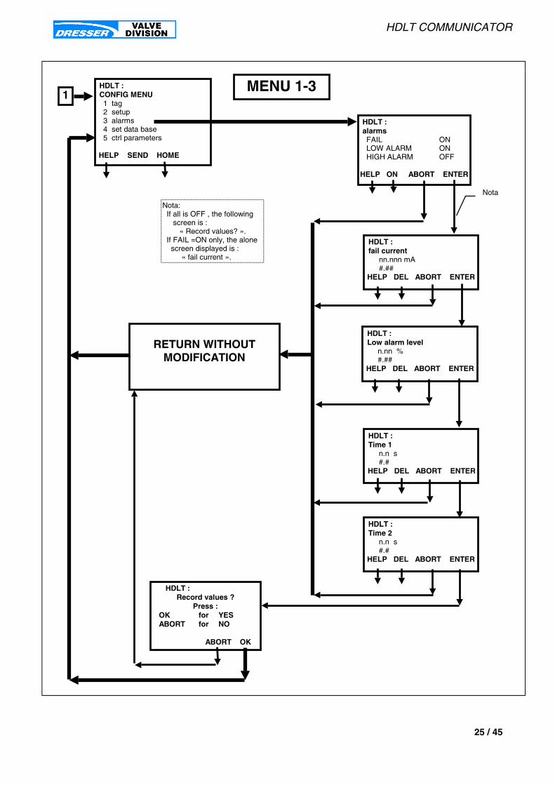
HDLT COMMUNICATOR
25 / 45
HDLT :alarmsFAIL ONLOW ALARM ONHIGH ALARM OFF
HELP ON ABORT ENTER
1HDLT :CONFIG MENU1 tag2 setup3 alarms4 set data base5 ctrl parameters
HELP SEND HOME
HDLT :fail current
nn.nnn mA#.##
HELP DEL ABORT ENTER
HDLT :Time 1
n.n s#.#
HELP DEL ABORT ENTER
RETURN WITHOUTMODIFICATION
HDLT :Time 2
n.n s#.#
HELP DEL ABORT ENTER
HDLT :Low alarm level
n.nn %#.##
HELP DEL ABORT ENTER
HDLT :Record values ?
Press :OK for YESABORT for NO
ABORT OK
MENU 1-3
Nota: If all is OFF , the following screen is : « Record values? ». If FAIL =ON only, the alone screen displayed is : « fail current ».
Nota
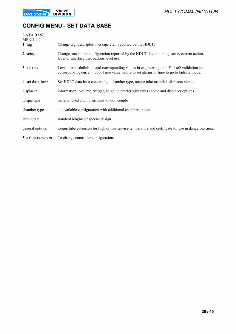
HDLT COMMUNICATOR
26 / 45
CONFIG MENU - SET DATA BASE
DATA BASEMENU 1-41 tag Change tag, descriptor, message etc... reported by the HDLT.
2 setup Change transmitter configuration reported by the HDLT like mounting sense, current action,level or interface use, buttons level use.
3 alarms Level alarms definition and corresponding values in engineering unit. Failsafe validation andcorresponding current loop. Time value before to set alarms or time to go to failsafe mode.
4 set data base Set HDLT data base concerning : chamber type, torque tube material, displacer size ...
displacer information : volume, weight, height, diameter with units choice and displacer options
torque tube material used and normalized torsion couple
chamber type all available configuration with additional chamber options
arm lenght standard lenghts or special design
general options torque tube extension for high or low service temperature and certificate for use in dangerous area.
5 ctrl parameters To change controller configuration.

HDLT COMMUNICATOR
27 / 45
HDLT :displacer weight nnnn.nnn xxx ####.###
HELP DEL ABORT ENTER
1
HDLT :CONFIG MENU &&&&1 tag2 setup3 alarms4 set data base5 ctrl parameters
HELP SAVE HOME
HDLT :displacer volumen.nn xxxxx#.##
HELP DEL ABORT ENTER
HDLT :volume unitliter liter CuIn
ABORT ENTER
RETURN WITHOUTMODIFICATION
HDLT :
Record values ?Press
OK for YESABORT for NO
ABORT OK
HDLT:weight unitgrgrkgpound
ABORT ENTER
HDLT :height unitmm in mm
ABORT ENTER
HDLT :displacer height
nnnn.nn xxxxx ####.## HELP DEL ABORT ENTER
HDLT :displacer diameter
nn.n xxx##.#
HELP DEL ABORT ENTER
MENU 1-4
TO MENU 1- 4-bisFROM MENU 1-4-bis

HDLT COMMUNICATOR
28 / 45
HDLT :torque tube
inconel/carbon inconel/carbon inconel/stainless
ABORT ENTER
HDLT :force1 force 1 force 2 force 4 force
ABORT ENTER
HDLT :arm lenght
arm 4 in not standard arm 4 in arm 8 in arm 16 in ABORT ENTER
75
FROM MENU 1- 4
HDLT :chamber type1230012301
ABORT ENTER
HDLT :displacer optionswith displacer ONnot standard OFFstainless steel ONextention rod OFF
OFF ABORT ENTER
RETURN WITHOUTMODIFICATION
HDLT :
Record values ?Press
OK for YESABORT for NO
ABORT OK
HDLT:chamber options special steel ON carbon steel OFF stainless steel OFF drain ON vent ON
OFF ABORT ENTER
Note 1
HDLT :general options extention HT/LT OFF intrinsic safety ON flameproof OFF weatherproof ON ON ABORT ENTER
Note 1
MENU 1-4-bis
TO MENU 1- 4
Note 1more configuration
available

HDLT COMMUNICATOR
29 / 45
CONFIG MENU - CTRL PARAMETERS
CTRL PARAMETERSMENU 1-51 tag Change tag, descriptor, message etc... reported by the HDLT.
2 setup Change transmitter configuration reported by the HDLT like mounting sense, current action,level or interface use, buttons level use.
3 alarms Level alarms definition and corresponding values in engineering unit. Failsafe validation andcorresponding current loop. Time value before to set alarms or time to go to failsafe mode.
4 set data base Set HDLT data base concerning : chamber type, torque tube material, displacer size ...
5 ctrl parameters To change controller configuration: setpoint startup, units for setpoint (SP) , direct or reverse actionand additional parameters.Remarks : the controller mode must be actived on the HDLT to allows to displaycontroller parameters and to change PID parameters.
Local SP unit Engineering units for the controller setpoint. A choice of many units is proposed . This unit is alsoused by Initial local SP, Low SP value, High SP value, SP low limit, SP high limit.
Ratio control Ratio control is ON : -if controller setpoint unit and level units are different . -if same unit but scale for setpoint and scale for level are not the same.Ratio control is automatically set in case of different units but not for different scale.If ratio control is ON, the two parameters RATIO GAIN and RATIO BIAS must be set using theformula : SP in process variable units = Ratio gain * SP in its units + Ratio bias
Initial local SP At power up , in case of micro-controller re-start or if HDLT RESET has been performed , this setpointwill be use by the controller.
Low SP value Controller setpoint low value corresponding to low level of liquid (Low level).
High SP value Controller setpoint high value corresponding to low level of liquid (High level).
SP low limit Minimum value for the setpoint allowed.
SP high limit Maximum value for the setpoint allowed.
Alarm Alarm type could be absolute or deviation. This alarm is done on the level of liquid.ABSOLUTE= alarm detection is done on the real level of liquid.DEVIATION=alarm detection is done on the error between the level of liquid and the controller setpointexpressed in the level engineering unit .
Low alarm limit Controller low alarm. Alarms can be absolute or deviation. This value is expressed in level engineeringunit. In case of deviation alarm, the Low alarm limit must be a negative number .
High Alarm Limit Controller high alarm. Alarms can be absolute or deviation. This value is expressed in level engineeringunit. In case of deviation alarm, the High alarm limit musy be a positive number .
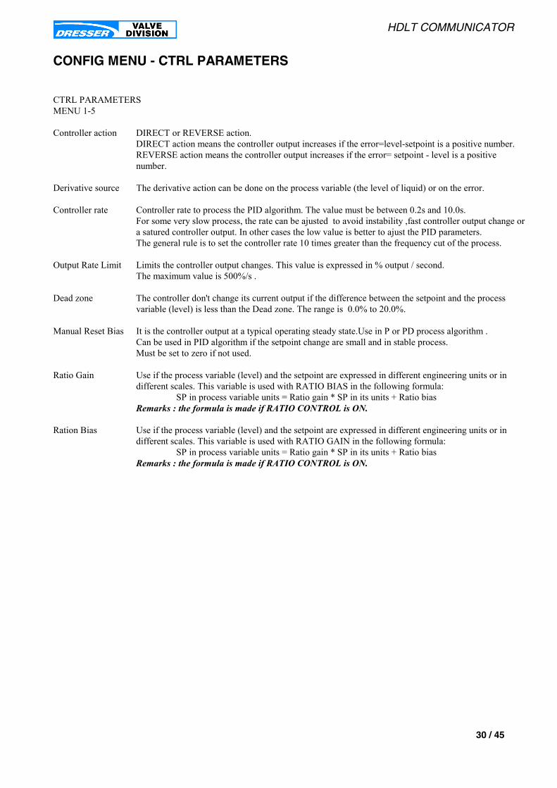
HDLT COMMUNICATOR
30 / 45
CONFIG MENU - CTRL PARAMETERS
CTRL PARAMETERSMENU 1-5
Controller action DIRECT or REVERSE action.DIRECT action means the controller output increases if the error=level-setpoint is a positive number.REVERSE action means the controller output increases if the error= setpoint - level is a positivenumber.
Derivative source The derivative action can be done on the process variable (the level of liquid) or on the error.
Controller rate Controller rate to process the PID algorithm. The value must be between 0.2s and 10.0s.For some very slow process, the rate can be ajusted to avoid instability ,fast controller output change ora satured controller output. In other cases the low value is better to ajust the PID parameters.The general rule is to set the controller rate 10 times greater than the frequency cut of the process.
Output Rate Limit Limits the controller output changes. This value is expressed in % output / second.The maximum value is 500%/s .
Dead zone The controller don't change its current output if the difference between the setpoint and the processvariable (level) is less than the Dead zone. The range is 0.0% to 20.0%.
Manual Reset Bias It is the controller output at a typical operating steady state.Use in P or PD process algorithm .Can be used in PID algorithm if the setpoint change are small and in stable process.Must be set to zero if not used.
Ratio Gain Use if the process variable (level) and the setpoint are expressed in different engineering units or indifferent scales. This variable is used with RATIO BIAS in the following formula: SP in process variable units = Ratio gain * SP in its units + Ratio biasRemarks : the formula is made if RATIO CONTROL is ON.
Ration Bias Use if the process variable (level) and the setpoint are expressed in different engineering units or indifferent scales. This variable is used with RATIO GAIN in the following formula: SP in process variable units = Ratio gain * SP in its units + Ratio biasRemarks : the formula is made if RATIO CONTROL is ON.

HDLT COMMUNICATOR
31 / 45
HDLT :Derivative source: ERROR 1 no change 2 ERROR 3 PV
ABORT ENTER
HDLT :Controller action:reverse 1 no change 2 direct 3 reverse
ABORT ENTER
HDLT :Alarm : ABSOLUTE 1 no change 2 absolute 3 deviation
ABORT ENTER
1HDLT :CONFIG MENU1 tag2 setup3 alarms4 set data base5 ctrl parameters
HELP SEND HOME
HDLT :Low SP value
nn.nn##.## DEL ABORT
HDLT :Record values ?
Press :OK for YESABORT for NO
ABORT OK
MENU 1-5HDLT :Local SP unit%
mAin
ABORT ENTER
HDLT :Ratio control : ON 1 no change 2 NO
3 YES ABORT ENTER
HDLT :Initial local SP
nn.nn##.##
DEL ABORT ENTER
HDLT :High SP value
nn.nn##.## DEL ABORT
HDLT :Low SP limit
nn.nn##.## DEL ABORT
HDLT :High SP limit
nn.nn##.## DEL ABORT
HDLT :Low Alarm Limit
nn.nn##.## HELP DEL ABORT
HDLT :High Alarm Limit
nn.nn##.##
HELP DEL ABORT ENTER
HDLT :Controller rate
n.nn s #.##HELP DEL ABORT ENTER
HDLT :Output Rate Limit in % /s:
nnn.nn ###.## DEL ABORT ENTER
HDLT :Dead zone :
n.n % #.#HELP DEL ABORT ENTER
HDLT :Manual Reset Bias :
nn.n % ##.#HELP DEL ABORT ENTER
HDLT :Ratio Gain :
nn.nn ##.##HELP DEL ABORT ENTER
HDLT :Ratio Bias :
nn.nn ##.##HELP DEL ABORT ENTER
All ABORT Keysgo out the displayed function
without modificationand return to
CONFIG MENU
Note 1:if ENTER is selected,a screen displays the closedvalue allowed to be recorded.
NOTE 1
NOTE 1

HDLT COMMUNICATOR
32 / 45
CALIBRATE MENU - TOOLSTOOLSMENU 2 For more information about the calibration principle see page 44 .
1 calibrate This sub menu allows the user to calibrate the transmitter and the specific gravity meter: ZERO and SPAN.
TRANSMITTER To calibrate the transmitter function.S.G. METER To calibrate the specific gravity meter function.
2 parameters This sub dialog allows to change the specific gravity(ies) of service , to change the upper and lowervalues for the current output signal. The values are typically 4 and 20 mA but may be any valuesbetween 3.8 and 20.5 mA. This dialog also allows to change the upper and lower values for the levelof liquid with a choice of engineering units, the output damping, the zero shift and the reduce span.
CHG SG SER To change the specific gravity(ies) of service if different from the calibration specific gravity(ies).SET VARIABLES to change the upper and lower values for the current output signal. The values are typically 4 and
20 mA but may be any values between 3.8 and 20.5 mA. This dialog also allows to change the upperand lower values for the level of liquid with a choice of engineering units, the output damping,the zero shift and the reduce span.
3 tools Coupling function between the electronic head and the torque tube. A good coupling correspond todisplay 0.0%. Values between +5.0% and -5.0% are acceptable. See the instruction manual formore information on the precise procedure to follow.This menu also allows to re-calibrate the current output but MUST BE DONE ONLY IF ABSOLUTLYNECESSARY.Current generator is also implemented to set different loop current to test or to calibrate othersloop devices.
4-20mA CAL SETCURRENT
The function allows to change the current to test for example different devices in serie in the loop.The range is 3.6 mA to 23.0 mA
4mA ADJ 4 mA re_calibration (trim DAC zero). This procedure must be done ONLY in case current outputis not correct regards reference milli-ampermeter in the loop.Method: -press 4 mA ADJ : using a current reference meter, read the current loop (ex: 4.52mA) -enter the value of the loop current (ex: 4.52mA). -go out : the 4 mA output current is recalibrated.
20mA ADJ 20 mA re_calibration (trim DAC gain). This procedure must be done ONLY in case current outputis not correct regards reference milli-ampermeter in the loop.Method: -press 20 mA ADJ : using a current reference meter, read the current loop (ex: 19..23mA) -enter the value of the loop current (ex: 19.23mA). -go out : the 20 mA output current is recalibrated.
OUT to come back to the CALIBRATE MENU. COUPLING coupling This procedure must be run during the coupling between the electronic head and the torque tube.
The value displays must be between -5% and +5%.See instruction manual before to run this procedure.
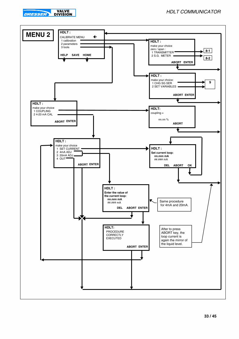
HDLT COMMUNICATOR
33 / 45
ABORT ENTER
PROCEDURE CORRECTLY EXECUTED
HDLT:
make your choicezero / span :1 TRANSMITTER2 S.G. METER
ABORT ENTER
MENU 2
HOMESAVEHELP
CALIBRATE MENU &1 calibration2 parameters3 tools
HDLT :
HDLT :
ABORT ENTER
make your choice:1 CHG SG SER2 SET VARIABLES
HDLT :
ABORT ENTER
make your choice1 COUPLING2 4-20 mA CAL
HDLT :
ABORT
coupling =
nn.nn %
HDLT:
8-1
8-2
9
make your choice1 SET CURRENT2 4mA ADJ3 20mA ADJ4 OUT
ABORT ENTER
HDLT :
ABORT OK
Set current loop: nn.nnn mA ##.### mA
HDLT :
DEL
ABORT ENTER
Enter the value ofthe current loop: nn.nnn mA ##.### mA
HDLT :
DEL
Same procedure for 4mA and 20mA.
After to pressABORT key, theloop current isagain the mirror ofthe liquid level.

HDLT COMMUNICATOR
34 / 45
CALIBRATE MENU - TRANSMITTER
MENU 8-1 For more information about the calibration principle see page 44 .
1 TRANSMITTER To calibrate the transmitter function.
1 SG CAL : This sub menu allows to specify the specific gravity(ies) of calibration for the ZERO and SPAN.In INTERFACE SERVICE: two specific gravities must be set.IN LEVEL SERVICE only one.
LOW SG CAL Specific gravity specified during the calibration procedure and corresponding to the LOWER liquidspecific gravity. This specific gravity is used only in INTERFACE MODE.
HIGH SG CAL Specific gravity specified during the calibration procedure and corresponding to the UPPER liquidspecific gravity. This specific gravity is used only in INTERFACE MODE.
SG CAL Specific gravity specified during the calibration procedure and corresponding to the liquidspecific gravity. This specific gravity is used only in LEVEL MODE.
2 ZERO To take the low level of liquid corresponding to 4.0mA or 20.0mA in the loop respectivelyfor direct or reverse loop current.
3 SPAN To take the high level of liquid corresponding to 20.0mA or 4.0mA in the loop respectivelyfor direct or reverse loop current.
4 OUT to return to CALIBRATE MENU.
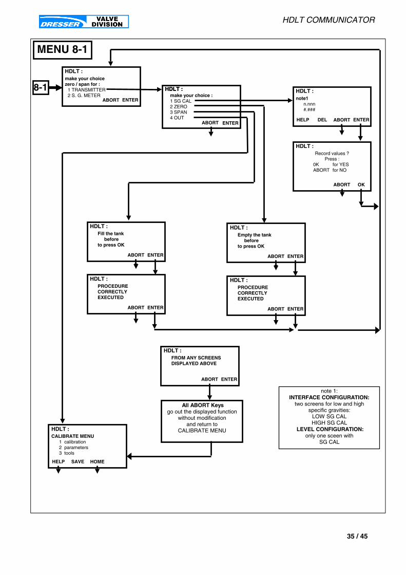
HDLT COMMUNICATOR
35 / 45
note1n.nnn#.###
MENU 8-1
note 1:INTERFACE CONFIGURATION:
two screens for low and highspecific gravities:
LOW SG CALHIGH SG CAL
LEVEL CONFIGURATION:only one sceen with
SG CAL
ABORT ENTER
Empty the tank beforeto press OK
HDLT :
HDLT :PROCEDURECORRECTLYEXECUTED
ABORT ENTER
make your choice :1 SG CAL2 ZERO3 SPAN4 OUT
ENTER
HDLT :
ABORT
HDLT :
HOMESAVEHELP
CALIBRATE MENU1 calibration2 parameters3 tools
HDLT :
HDLT :
ABORT ENTER
make your choicezero / span for :
1 TRANSMITTER2 S. G. METER
ABORTDELHELP ENTER
HDLT :
ABORT OK
Record values ?Press :
0K for YESABORT for NO
HDLT :
ABORT ENTER
Fill the tank beforeto press OK
HDLT :
ABORT ENTER
PROCEDURECORRECTLYEXECUTED
HDLT :
All ABORT Keysgo out the displayed function
without modificationand return to
CALIBRATE MENU
HDLT :FROM ANY SCREENSDISPLAYED ABOVE
ABORT ENTER
8-1
HDLT COMMUNICATOR
36 / 45
CALIBRATE MENU - SG METER
MENU 8-2 For more information about the calibration principle see page 44 .
2 S. G. METER To calibrate the specific gravity meter function.
1 ZERO To take the displacer position corresponding to the specific gravity 0.0.The displacer chamber must be EMPTY.
2 SPAN SG CAL: Specific gravity specified during the calibration procedure and correspondingto the liquid specific gravity. To take the displacer position corresponding to the specificgravity of calibration : SG CAL.The displacer must be fully immersed with the liquid of specific gravity SG CAL.
3 RESET TO FACTORY In case of bad calibration of the specific gravity meter, this function allows the user tocome back on to the factory calibration data.
4 OUT to return to CALIBRATE MENU.
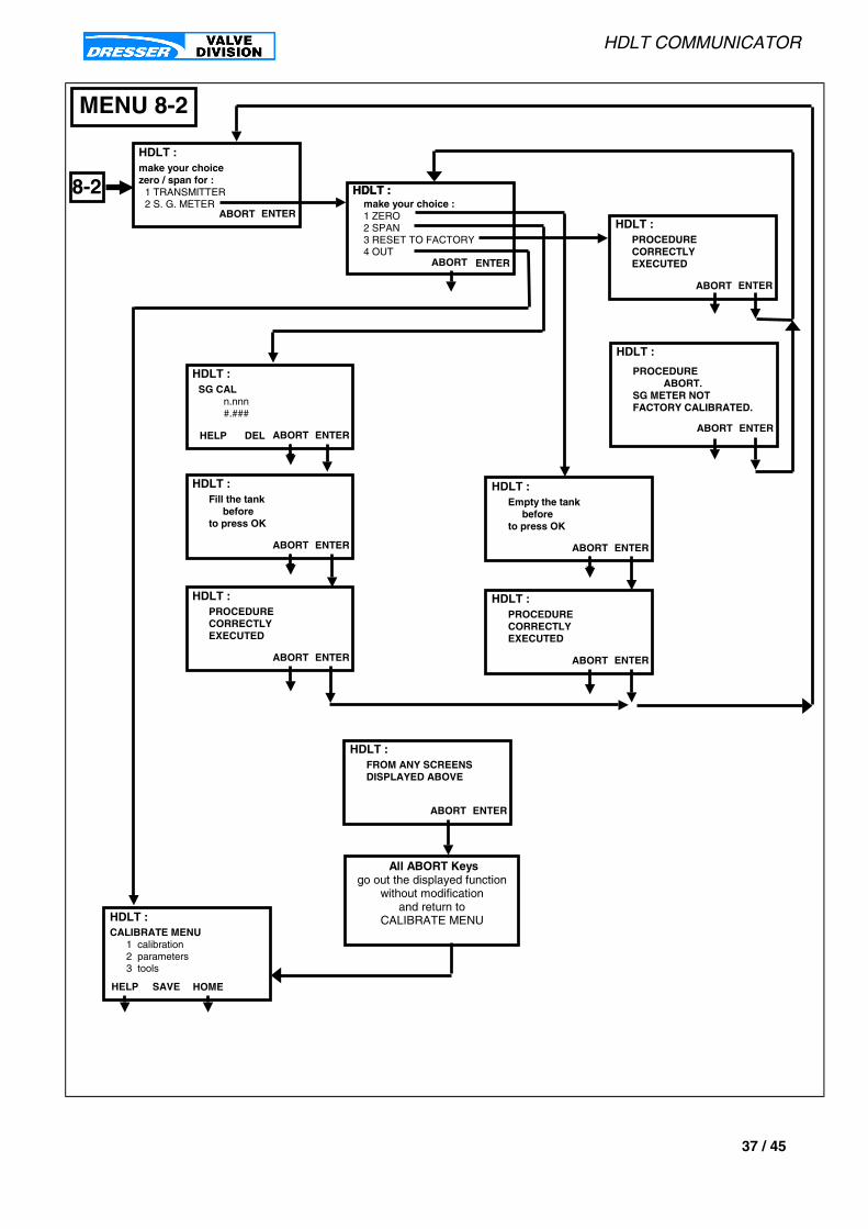
HDLT COMMUNICATOR
37 / 45
SG CAL n.nnn #.###
MENU 8-2
ABORT ENTER
Empty the tank beforeto press OK
HDLT :
HDLT :PROCEDURECORRECTLYEXECUTED
ABORT ENTER
make your choice :1 ZERO2 SPAN3 RESET TO FACTORY4 OUT
ENTER
HDLT :
ABORT
HDLT :
HOMESAVEHELP
CALIBRATE MENU1 calibration2 parameters3 tools
HDLT :
HDLT :
8-2ABORT ENTER
make your choicezero / span for :
1 TRANSMITTER2 S. G. METER
ABORT ENTER
Fill the tank beforeto press OK
HDLT :
ABORT ENTER
PROCEDURECORRECTLYEXECUTED
HDLT :
All ABORT Keysgo out the displayed function
without modificationand return to
CALIBRATE MENU
HDLT :FROM ANY SCREENSDISPLAYED ABOVE
ABORT ENTER
ABORT ENTER
HDLT :
DELHELP
ABORT ENTER
PROCEDURECORRECTLYEXECUTED
HDLT :
ABORT ENTER
PROCEDURE ABORT.SG METER NOTFACTORY CALIBRATED.
HDLT :
HDLT COMMUNICATOR
38 / 45
CALIBRATE MENU - PARAMETERS
MENU 9 For more information about the calibration principle see page 44 .
1 CHG SG SER To calibrate the transmitter function.
LOW SG SER This specific gravity is normally the same as the low specific gravity of calibration (LOW SG CAL)but need to be change if the lower specific gravity of the process has changed and not equal tothe low specific gravity of calibration (LOW SG CAL).This specific gravity is used only in INTERFACE MODE.
HIGH SG SER This specific gravity is normally the same as the high specific gravity of calibration (HIGH SG CAL)but need to be change if the upper specific gravity of the process has changed and not equal tothe upper specific gravity of calibration (HIGH SG CAL).This specific gravity is used only in INTERFACE MODE.
SG SER This specific gravity is normally the same as the specific gravity of calibration (SG CAL)but need to be change if the specific gravity of the process has changed and not equal tothe specific gravity of calibration (SG CAL).This specific gravity is used only in LEVEL MODE.
2 SET VARIABLESDamping Output current filtering. This value is expressed in second and corresponding to T63% for a first
order response time.
Low current Low output current for low level of liquid (direct acting) or low output current for high levelof liquid (reverse acting). Must be between 3.8 mA and 14 mA and lower than High Current.
High Current High output current for high level of liquid (direct acting) or high output current for low levelof liquid (reverse acting). Must be between 8.0 mA and 20.5 mA and greater than Low current.
Low Level Value in engineering units for low level and corresponding to zero calibration.
High Level Value in engineering units for high level and corresponding to span calibration.
Units Engineering units for Low and High Level.Available units are: %, mm, cm, m, liter, m3, inch, feet, cu_inch, cu_feet, kg, gr, pound.
Zero Shift Value in percentage of calibration scale (zero/span) to shift the ZERO in an other position.The current output is automatically re-ajusted at this new ZERO position.
Reduce Span Value in percentage of calibration scale (zero/span) to reduce the SPAN.The current output is automatically re-ajusted to take into account this new SPAN.
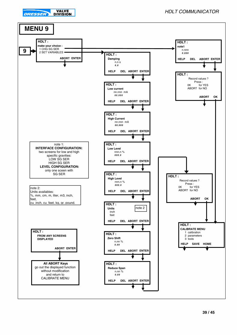
HDLT COMMUNICATOR
39 / 45
Damping n.n s #.#
ABORT ENTER
HDLT :
DELHELP
Low current nn.nnn mA ##.###
ABORT ENTER
HDLT :
DELHELP
High Current nn.nnn mA ##.###
ABORT ENTER
HDLT :
DELHELP
Low Level nnn.n % ###.#
ABORT ENTER
HDLT :
DELHELP
High Level nnn.n % ###.#
ABORT ENTER
HDLT :
DELHELP
Units inch feet
ABORT ENTER
HDLT :
DELHELP
note 2
Zero Shift n.nn % #.##
ABORT ENTER
HDLT :
DELHELP
Reduce Span n.nn % #.##
ABORT ENTER
HDLT :
DELHELP
note1n.nnn#.###
MENU 9
note 1:INTERFACE CONFIGURATION:
two screens for low and highspecific gravities:
LOW SG SERHIGH SG SER
LEVEL CONFIGURATION:only one sceen with
SG SER
HOMESAVEHELP
CALIBRATE MENU1 calibration2 parameters3 tools
HDLT :
9ABORTDELHELP ENTER
HDLT :
ABORT OK
Record values ?Press :
0K for YESABORT for NO
HDLT :
All ABORT Keysgo out the displayed function
without modificationand return to
CALIBRATE MENU
HDLT :FROM ANY SCREENSDISPLAYED
ABORT ENTER
note 2:Units availables:%, mm, cm, m, liter, m3, inch,feet,cu_inch, cu_feet, kg, gr, pound.
ABORT OK
Record values ?Press :
0K for YESABORT for NO
HDLT :
make your choice :1 CHG SG SER2 SET VARIABLES
HDLT :
ABORT ENTER

HDLT COMMUNICATOR
40 / 45
DIAGNOSTIC MENU
MENU 3DIANOSTIC MENU
1 diagnostic data Read continuous diagnostic data: total filling up, time tank empty, time tank full,time transmitter working
nbr of filling up Total number of filling tanks.
time tank empty Time in days for tank empty.
time tank full Time in days for tank full .
time working Time in days for HDLT working.
internal temp Indicate the internal temperature inside the HDLT head.
2 reset continuous Reset continuous diagnostic data : total filling up, time tank empty, time tank full,time transmitter working. These variables are set to 0. The previous data are lost andmust be recorded to be used later.
3 sensor test Sensor check procedure. This test must be run ONLY IF THE LIQUID LEVEL IS STABLE toavoid to go to FAILSAFE MODE.
4 smart filtering This sub menu allow to change manually or automatically the smart filtering variables to suppressnoise , waves in the displacer chamber or wave in the tank and accordingly to reduce the currentoutput variation.
manual tune The user can read and change the parameters value described below one by one .
W INTG Integration window expressed in seconds.The scale must be between 0.1s and 32.0s .
DZ INTG Dead zone expressed in % of zero /span calibration. The scale must be between 0.01% and 10.0% .
W VAL Validation window expressed in seconds.The scale must be between 0.1s and 32.0s .
auto tune The three above parameters are found automatically with the target to reduce the current outputvariation below 0.3% of the full span.
5 SG meter The specific gravity meter allow the user to read an unknown specific gravity. Be sure the displaceris fully immersed to avoid wrong measurement.
6 fault historic To read all the transmitter tempory faults which have been cleared by the transmitter if not remained.The faults displayed are the same as : INFO / 1 read fault(s).

HDLT COMMUNICATOR
41 / 45
HDLT :time working =
n dayinternal temp =
nn.n °CABORT OK
3HDLT :DIAGNOSTIC MENU &&&&1 diagnostic data2 reset continuous3 sensor test4 smart filtering5 SG meter6 fault historic
HELP SAVE HOME
HDLT :WAIT
SENSOR TESTIN PROGRESS
ABORT
HDLT :
RESET CONTINUOUS DATACORRECTLY EXECUTED
ABORT OK
HDLT :Af ter reset t ing , thecur rent va lues wi l lbe los t . P ress ABORTi f you need theseva lues
ABORT OK
MENU 3
HDLT :nbr of filling up =
n.n tanktime tank empty =
n daytime tank full =
n dayABORT OK
HDLT :
TEST PASS
ABORT OK
HDLT :Be sure that thed isp lacer i s fu l l yimmersed. .
ABORT OK
NOTE 2
NOTE 2ABORT key don’t wait the test
result and return toDIAGNOSTIC MENU
This take around 15 seconds.The message is:
« procedure abortedTRY AGAIN »
some seconds
HDLT :
SG = n.nnn
ABORT
NOTE 1
NOTE 1If the S.G. METER has notbeen previously calibrated
the screen message is:« SPECIFIC GRAVITY
METER NOTCALIBRATED »
ABORT OK
make your choice :1 manual tune2 auto tune
HDLT :
ABORT ENTER
HDLT :
AUTO TUNE CORRECTLY EXECUTED
ABORT OK
HDLT :W AIT
AUTO TUNEIN PROGRESS
ABORT
NOTE 3
NOTE 3In case of problems to
research the parameters,the message below is displayed
« PROCEDURE STOPPED »
ABORT OK
ABORT ENTER
HDLT :
DELHELP
W INTG (s) nn.n s
##.#
HDLT :W INTG = n.n sDZ INTG = n.nn%W VAL = n.nnn s
ABORT OK
HDLT :DZ INTG (%) n.nn
#.## DEL ABORT
HDLT :W VAL (s) n.nn
#.## DEL ABORT
ABORT OK
Record values ?Press :
0K for YESABORT for NO
HDLT :
All ABORT Keysgo out the displayed function
without modificationand return to
CALIBRATE MENU
HDLT :FROM ANY SCREENSDISPLAYED
ABORT ENTER
NOTE 2
some seconds later
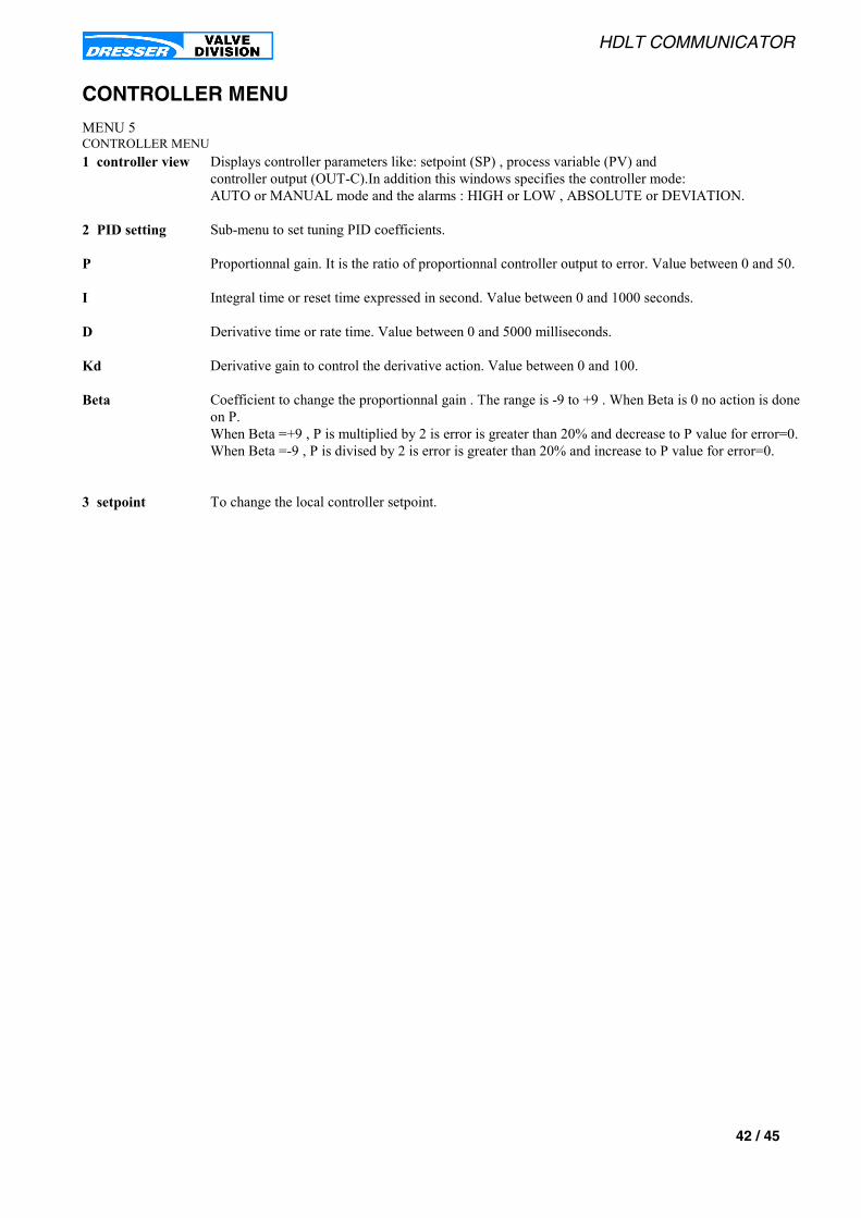
HDLT COMMUNICATOR
42 / 45
CONTROLLER MENU
MENU 5CONTROLLER MENU1 controller view Displays controller parameters like: setpoint (SP) , process variable (PV) and
controller output (OUT-C).In addition this windows specifies the controller mode:AUTO or MANUAL mode and the alarms : HIGH or LOW , ABSOLUTE or DEVIATION.
2 PID setting Sub-menu to set tuning PID coefficients.
P Proportionnal gain. It is the ratio of proportionnal controller output to error. Value between 0 and 50.
I Integral time or reset time expressed in second. Value between 0 and 1000 seconds.
D Derivative time or rate time. Value between 0 and 5000 milliseconds.
Kd Derivative gain to control the derivative action. Value between 0 and 100.
Beta Coefficient to change the proportionnal gain . The range is -9 to +9 . When Beta is 0 no action is doneon P.When Beta =+9 , P is multiplied by 2 is error is greater than 20% and decrease to P value for error=0.When Beta =-9 , P is divised by 2 is error is greater than 20% and increase to P value for error=0.
3 setpoint To change the local controller setpoint.
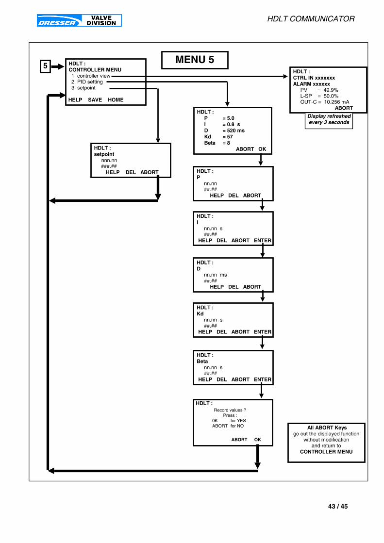
HDLT COMMUNICATOR
43 / 45
HDLT : P = 5.0 I = 0.8 s
D = 520 ms Kd = 57 Beta = 8
ABORT OK
5 HDLT :CONTROLLER MENU1 controller view2 PID setting3 setpoint
HELP SAVE HOME
MENU 5HDLT :CTRL IN xxxxxxxALARM xxxxxx
PV = 49.9%L-SP = 50.0%OUT-C = 10.256 mA
ABORT
HDLT :P
nn.nn##.## HELP DEL ABORT
HDLT :I
nn.nn s##.##
HELP DEL ABORT ENTER
HDLT :setpoint
nnn.nn ###.##
HELP DEL ABORT
All ABORT Keysgo out the displayed function
without modificationand return to
CONTROLLER MENU
HDLT :D
nn.nn ms##.## HELP DEL ABORT
HDLT :Kd
nn.nn s##.##
HELP DEL ABORT ENTER
HDLT :Beta
nn.nn s##.##
HELP DEL ABORT ENTER
ABORT OK
Record values ?Press :
0K for YESABORT for NO
HDLT :
Display refreshedevery 3 seconds
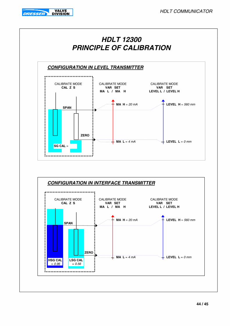
HDLT COMMUNICATOR
44 / 45
LEVEL L = 0 mm
SPAN
ZERO
CALIBRATE MODECAL Z S
CALIBRATE MODEVAR SET
MA L / MA H
CALIBRATE MODEVAR SET
LEVEL L / LEVEL H
LEVEL H = 560 mm
MA L = 4 mA
MA H = 20 mA
CONFIGURATION IN LEVEL TRANSMITTER
SG CAL =
ZEROLEVEL L = 0 mm
SPAN
CALIBRATE MODECAL Z S
CALIBRATE MODEVAR SET
MA L / MA H
CALIBRATE MODEVAR SET
LEVEL L / LEVEL H
LEVEL H = 560 mm
MA L = 4 mA
MA H = 20 mA
CONFIGURATION IN INTERFACE TRANSMITTER
LSG CAL = 0.56
HSG CAL = 0.96
HDLT 12300PRINCIPLE OF CALIBRATION

HDLT COMMUNICATOR
45 / 45
TRADEMARK INFORMATION
HART® is a Registered trademark of the HART Communication Foundation,
Austin, Texas, USA.
Model 275 HART® Communicator is a product of Fisher Rosemount Systems, Inc.

AUSTRIAMasoneilan HP+HP GmbHHans-Kudlich-Str. 35A 2100 Korneuburg - AustriaTelephone/Fax : 02262 63689
BELGIUMMasoneilan Division of Dresser Europe S.A.281-283, Chaussée de Bruxelles1190 BRUSSELS - BelgiumTelephone 02 344 09 70 Fax 02 344 11 23
BRAZILDresser Idustria E Comercio Ltda Divisao MasoneilanRua Senador Vergueiro, 43309521-320 Sao Caetano Do SulSao Paulo - BrazilTelephone 55 11 453 5511 Fax 55 11 453 5565
CANADADresser Canada, Inc.Valve & Controls Division5010 North Service RoadBurlington, Ontario, L7L 5R5 - CanadaTelephone 1-905-335-3529Fax 1-905-336-7628
Dresser Canada, Inc.Valve & Controls Division3530 78 th AvenueEdmonton, Alberta T6B 2X9 - CanadaTelephone 1-403-465-7882Fax 1-403-468-0934
FRANCEDresser Produits Industriels Division Masoneilan4, place de Saverne92971 Paris La Défense Cedex FranceTelephone 33 1 49 04 90 00Fax 33 1 49 04 90 10
Lyon Distribution Center55, rue de la Mouche 69540 Irigny - France Telephone 33 4 72 39 06 29Fax 33 4 72 39 21 93
GERMANYMasoneilan - HP+HP GmbHHead Office : 47860 Willich Postfach 120847877 Willich Klein-Kollenburg Strasse 78-80GermanyTelephone 49 2156 9189-0 Fax 49 2156 41058
GERMANY (continuation)
Masoneilan - HP+HP GmbHUhlandstrasse 58 - 60314 Frankfurt GermanyTelephone 49 69 439350Fax 49 69 4970802
Masoneilan - HP+HP GmbHGoethestrasse 170006237 LeunaGermanyPhoneFax 49 03461 434443
ITALYMasoneilan - Division of Dresser Italia S.p.A.Headquarters, Sales Office, Plant and After Sales : Via Cassano 77 80020 Casavatore (Naples) - ItalyTelephone (081) 7892111 Fax (081) 7892208
North Italy Sales Office :C.soGaribaldi 113 20121 Milan - ItalyTelephone (02) 29005683/84 Fax (02) 29005660
JAPANNiigata Masoneilan Valve Service Company26th fl., Marive East TowerWBG 2-6 Nakase, Mihama-ku Chiba-shi, Chiba, 261-71 - JapanTelephone 81-43-297-9242Fax 81-43-299-1115
LATIN AMERICADresser Valve & Controls Division10556 NW 26th Street, Suite D-201Miami, Florida 33172 - U.S.A.Telephone 1-305-470-2766Fax 1-305-470-2743
MEXICOMasoneilan Internacional, S.A. de C.v.Henry Ford n° 114, Esq. FultonFraccionamiento Industrial San Nicolas54030 Tlalnepantla, MexicoTelephone 52-5-310-9863Fax 52-5-310-5584
MIDDLE EAST REGIONDresser Valve & Controls DivisionMiddle East OperationsUnit JAO1 and JAO2 Roundabout 8Jebel Ali Free ZoneUnited Arab EmiratesTelephone 971-4-838-752Fax 971-4-838-038
NETHERLANDSDresser Industrial Products B.V.Masoneilan DivisionSteenhouwerstraat 11 - 3194 AG Hoogvliet P.O. Box 6403190 AN Hoogvliet RTThe NetherlandsTelephone 010-4384122Fax 010-4384443
SINGAPOREDresser Valve & Controls Far East16, Tuas Ave 8 - Singapore 639231Telephone 65-861-6100Fax 65-861-7172
SOUTH AFRICADresser LimitedValve & Controls DivisionP.O. Box 2234 - 16 Edendale RoadEastleigh, Edenvale 1610Transvaal, Republic of South AfricaTelephone 27-11-452-1550Fax 27-11-452-2903
SPAINMasoneilan S.A.Zona Franca, Sector M, Calle Y08040 Barcelona - SpainTelephone 3 223 41 75/223 41 28 Fax 3 223 47 54
UNITED KINGDOMValve & Controls - Dresser U.K. LtdTrevithick WorksGillibrands Estate, SkelmersdaleLancashire WN8 9TU - EnglandTelephone 44-1695-52600Fax 44-1695-720175
Valve & Controls - Dresser U.K. LtdU.K. Sales Office :Unit 5, Brook Business CentreCowley Mill Road, UxbridgeMiddx UB8 2FX - EnglandTelephone 44-1895-454900Fax 44-1895-454919
UNITED STATESDresser Valve & Controls DivisionMasoneilan North America Operations 85 Bodwell StreetAvon, Massachusetts 02322-1190Telephone 1-508-586-4600Fax 1-508-941-5497
Dresser Valve & Controls Division15112 Morales Road (77032)P.O. Box 60078Houston, Texas 77205-0078Telephone 1-281-871-6500Fax 1-281-871-6569
PLANTS, SPARE PARTS and AFTER SALES DEPARTMENTS: 3, rue Saint–Pierre – 14110 Condé–sur–NoireauTelephone : 33 2 31 59 59 59 - Fax : 33 2 31 59 59 60 - E-mail : [email protected]
Sales Officesand Distribution
Centers
TRADEMARK INFORMATION
HART¨
is a Registered trademark of the HART Communication Foundation,Austin, Texas, USA.
Model 275 HART¨ Communicatoris a product of Fisher Rosemount Systems, Inc.


![RESCUE LIFTING DEVICE RUP 502-[] INSTRUCTION MANUAL](https://static.documents.pub/doc/80x56/61864a898318cc40a41c553a/rescue-lifting-device-rup-502-instruction-manual.jpg)


