51
Interactive Design Systems MC3D™ Short Bench Casting Geometry Control For Windows Version 1.1 User’s Manual Application Status: Version 1.1 Doc. Status: Final Last Update: 8 September 2007

Interactive Design Systems
MC3D™ Short Bench Casting Geometry
Control For Windows Version 1.1 User’s Manual
Application Status: Version 1.1
Doc. Status: Final
Last Update: 8 September 2007

2 MC3D User’s Manual
Interactive Design Systems v.8 September 2007
Copyright
About MC3D Version 1.1
Copyright © 2002-2007 Interactive Design Systems
Copyright Copyright © 2002-2007 Interactive Design Systems. ALL RIGHTS RESERVED. No part of this publication may be reproduced, transmitted, transcribed, stored in a retrieval system, or translated into any language in any form without prior written consent from Interactive Design Systems. The software applications described in this manual, including the manual and any associated media, is copyrighted and contains proprietary information that is subject to change without notice. All other trademarks or registered trademarks are acknowledged as the exclusive property of their respective owners.
Interactive Design Systems Interactive Design Systems 16885 Via Del Campo Ct., Suite #207 San Diego CA 92127
Phone: (858) 674-4196 or (800) 326-5525 E-mail: [email protected] Web: http://www.ids-soft.com

Contents 3
Interactive Design Systems v.8 September 2007
Contents
Chapter 1 — Introduction_________________________________________ 5 Short Line Match Casting ...................................................................................................7 Geometry Control for Short Line Casting ............................................................................8
Chapter 2 — Structure Geometric Definition _________________________ 9 Roadway Alignments ........................................................................................................10 3D Spine Curve ................................................................................................................10 Span Distribution – Pier Stations ......................................................................................11
Chapter 3 — Structure Topology - Segments And Joints______________ 13 Span Configuration - Segment Distribution .......................................................................13 Joints................................................................................................................................13 3D Coordinates of Control Points and Survey Markers .....................................................13
Chapter 4 — Match-Casting ______________________________________ 15 Concept and Applicability .................................................................................................15 Casting Cell and Bulkheads..............................................................................................19 Starter Segment vs. Typical Segment...............................................................................19 Survey and As-Cast - Method of Geometry Control ..........................................................20
Chapter 5 — Survey and As-Cast Coordinates ______________________ 23 Chapter 6 — MC3D Program Overview_____________________________ 27
Options.............................................................................................................................27 Chapter 7 — MC3D Program Architecture __________________________ 29
Project Definition ..............................................................................................................30 Joint Coordinates..............................................................................................................31 Camber Diagram ..............................................................................................................33 Starter Segment Set-Up ...................................................................................................34 Typical Segment Set-Up...................................................................................................37 Survey ..............................................................................................................................37 As-Cast Coordinates ........................................................................................................40 Reports.............................................................................................................................42
Chapter 8 — Working with MC3D _________________________________ 45 Installation and Registration .............................................................................................45 Getting Started .................................................................................................................45 The Casting Cycle – Geometry Control and Survey ..........................................................46

4 MC3D User’s Manual
Interactive Design Systems v.8 September 2007
Chapter 9 — MC3D Reporting ____________________________________ 49 Project Report ..................................................................................................................49 Casting Cell Reports.........................................................................................................49
Chapter 10 — General Remarks __________________________________ 51 Units.................................................................................................................................51 Survey and As-Cast Accuracy ..........................................................................................51 Erection Control................................................................................................................51

Chapter 1 — Introduction 5
Interactive Design Systems v.8 September 2007
Chapter 1 — Introduction PRESTRESSED concrete segmental bridges evolved in Europe as the need arose to eliminate the use of conventional falsework, which, in many cases was impractical or economically prohibitive. Today this bridge type is used for almost any conceivable site condition and has extended the practical competitive economic span range of concrete bridges. Its popularity has increased steadily over the years, as engineers have developed a better understanding of the time-dependent behavior of the materials (concrete creep and shrinkage, steel relaxation).
Jean Muller made the first application of precast segmental box girder construction in 1962, to the Choisy-le-Roi Bridge over Seine River in France. The contribution to the concept of segmental construction was significant because it offered the engineer superior quality control of the bridge elements by using factory-produced precast concrete.
Because the fabrication of the bridge can be accomplished while the substructure is being constructed, the erection period is accelerated and the time required to gain strength in the concrete is removed from the critical path. As a result of the maturity of the concrete at the time of erection, the effects of concrete creep and shrinkage are reduced. The match cast joint method of precasting concrete segments has proved to be the most versatile and reliable way to building precast segmental bridges. With proper geometry control, this method is ideal for building structures with complex geometry.
CONCEPT OF SEGMENT LAYOUT – The match-cast method presents several advantages for precasting concrete segments. The primary advantage is in the area of geometry control. Two different methods have been commonly used:
• Long Bench, where all segments are precast together on a long bench, usually with sliding formwork.
• Short Cell Method, where each segment is cast separately. The “cell” forms are for one segment (Fig. 2).
The “short cell casting method is usually preferred for variable curvature in plan and elevation.
IMPACT OF GEOMETRY ON SEGMENT LAYOUT – The structure geometry has great impact on the casting method and the layout of concrete segments at the design stage. Span lengths are determined on the basis of structural stability, economics, and on other site related constraints. Segment lengths are determined together with the construction method, lifting and erection equipments, and casting cell geometric considerations. For spans on a tight curve (access ramps), span layout and segment lengths as well as location of cast-in-place joints have considerable impact on constructability.

6 MC3D User’s Manual
Interactive Design Systems v.8 September 2007
MATCH CAST JOINTS – In the short cell method, each segment is cast, and subsequently moved into “match-cast” position before pouring the next segment. Placement of the match-cast segment is of primary concern to accommodate the geometry. In this process a 3-D curve along the box centerline must be followed accurately to accommodate both horizontal and vertical alignments. In addition, the cross-fall must be accounted for, together with predicted long-term structural deflections for proper placement of the match-cast segment (casting Curves). The accuracy of calculations and proper control of relative placement in the cell will greatly determine the degree of success of the erection process and the final geometry of the constructed structure.
BULKHEAD PLACEMENT – In the short cell casting method the bulkhead remains fixed and perpendicular to the centerline of the segment being cast (Fig. 3). This simplifies the cell adjustments to simply extending the forms to the match cast segment in place. The only adjustment to the fixed bulkhead side consists in placement of the post-tensioning ducts at proper locations. Placing the match-cast segment in the casting-cell requires local coordinates of the match cast segment (control points are established with bolts/stirrups and hairpins embedded in the top slab).
Figure 1. Fixed Bulkhead Orientation

Chapter 1 — Introduction 7
Interactive Design Systems v.8 September 2007
Short Line Match Casting Match casting is the term used to describe the method of casting one segment adjacent to its neighbor so that when the segments are erected together in their final location in the bridge, they fit together precisely. In some cases where since no glue or other filling material is used ("dry joints"), the exact match between segments is even more vital.
Normally epoxy glue is used to lubricate the joint and to provide a waterproof seal to the pre-stressing tendons. When all tendons are external, the joint does not need to be waterproofed, and the time saved in not applying the glue enables construction rates to be increased. The lack of glue does mean that the shear interface between segments requires more consideration, but overall benefits can be obtained from the dry jointed system.
The match-casting set-up comprises a number of moulds with bulkhead, soffit and side forms. A central moveable core form enables the trapezoidal cross section to be cast. In addition, one end of the mould allows a previously cast segment to form the stop end for the segment currently being cast. This previously cast segment forms the match cast face ensuring a perfect fit during erection.
To Storage
Inner Core
Fixed Bulkhead
Match Cast Segment
Wet Cast Segment
SHORT CELL METHOD
Figure 2. Short Cell Casting Method

8 MC3D User’s Manual
Interactive Design Systems v.8 September 2007
Geometry Control for Short Line Casting The structure geometry has great impact on the casting method and the layout of concrete segments at the design stage.
The goal of the geometry control program will be to monitor the casting operations and establish “as-cast” curves step-by-step to verify that the actual superstructure geometry is in close agreement with the geometry described in the design documents.
After each segment is cast, the position of this segment is established in the general plot of the structure. Comparing the location of the newly cast segment with the location assumed in the design geometry will allow for the determination of the adjustments required before the next pour.
It is important to understand that the geometry is solely dictated by the position of the match cast segment, the new cast segment is always poured in the same stationary form against a fix bulkhead. In reality, the new cast segment forms can be slightly deformed to match the fix bulkhead on one side and the front of the match cast segment on the other side.
The position of the match cast segment is monitored by using four elevation bolts generally placed above the webs close to the extremities of the segment and two centerline survey markers. For a straight bridge in plan and elevation, the segments are simply moved from wet cast to match cast position in a straight line.
For a bridge with a vertical curve the segments are first moved in a straight line to the match cast position, then tilted around a horizontal axis parallel to the joints.
For a bridge with horizontal curve, without super-elevation variation, the segments are first moved in a straight line to the match cast position, and then tilted around a vertical axis passing through the centerline at the front of the segment.
Finally, variable super-elevation can also be obtained by tilting the match cast segment around a horizontal axis perpendicular to the segment joint.
Therefore, short cell casting provides the ability for following any kind of superstructure geometry in three dimensions. Other advantages of the short cell are the limited space required in the casting yard and the stationary location of the forming system. Efficient means of adjustments must be designed into the match- cast segment soffit to limit the amount of time required for these operations.
The geometry of the bridge is actually determined by the casting yard and will be difficult to adjust at the time of erection. It is therefore very important to properly monitor the geometry in the casting yard.

Chapter 2 — Structure Geometric Definition 9
Interactive Design Systems v.8 September 2007
Chapter 2 — Structure Geometric Definition The structure geometric definition results from the placement of concrete segments defined along a 3D spine curve defining the centerline of girder. This centerline may be generated in various ways, by using “COGO-like” roadway geometry software.
The segment placement rules may be somewhat complex, depending on project geometric assumptions. In all cases, the placement rules lead to 3D joints that are placed perpendicular to the centerline of segment, in order to satisfy the cell basic geometric configuration, i.e.:
The structure is broken-down into “sub-structures” which will be cast as a unit. In MC3D, these units are called “casting-sets”. Casting-Sets are made of a “Starter” segment (the first segment to be cast), and a succession of typical segments following the casting rules. MC3D does not make any specific assumptions regarding the direction of casting (up-station or down-station), but simply assumes the first segment is the “starter” segment, and all subsequent segments are given in the order of casting.
The basic data given to MC3D is a series of 3-Dimensional general coordinates provided in a conventional “Right-Hand Rule” System of Coordinates. Three “control points” are given for each joint. The orientation of the general axes (X, Y, Z) is basically arbitrary – but the Z axis is by convention vertical and Z is positive upward.
Version 1.1 of MC3D accepts control point coordinates for crowned top slab. The program simply creates a fictitious centerline point that is uses internally (mid-point between East and West).
The bulkhead joint is always perpendicular to the longitudinal axis of the casting-cell.
Control Point Coordinates are provided in a “Right Hand Rule” General System of coordinates, in which the Z axis is vertical and z values are positive upward.

10 MC3D User’s Manual
Interactive Design Systems v.8 September 2007
Roadway Alignments The structure centerline is a 3D “spine” curve resulting from the geometry of several roadway “alignment” curves. They can be:
• Baseline alignment
• “Offset” alignment
• Profile Grade Line (PGL)
and can also be the result of applying various roadway design conditions, such as:
• Super-elevation and Transitions
• Constant or Variable roadway width conditions
3D Spine Curve Based on roadway design standards, these geometric alignments and conditions provide a set of parameters needed to determine the 3D location of the structure centerline points. Once obtained (either using computer programs such as COGO or other 3D Bridge Geometry programs), the general coordinates of base points (without applying final camber) are given to the MC3D program in the form of a table of X, Y and Z coordinates for:
• Centerline Point
• East Control Point
• West Control Point
MC3D Version 1.1 accepts control point coordinates for top slabs with a crown.

Chapter 2 — Structure Geometric Definition 11
Interactive Design Systems v.8 September 2007
Span Distribution – Pier Stations Based on the roadway geometry described above, and pier stations, it is possible to locate all segments for a “casting-set” (a span, or a cantilever arm) – and the general coordinates must be oriented according to the MC3D axes assumptions. The sketch below shows the orientation of axes to satisfy MC3D coordinate systems.
FIXED BULKHEAD
FIXED BULKHEAD
Left
+ Station
C Bridge
L
Baseline
Right
Match Cast
Wet CastWet
Cast
Match Cast
WEST LINE
EAST LINETowards Pier
CalledNorth
Toward
s Pier
WES
T LIN
E
EAST
LINE
Calle
dNo
rth
Figure 3. Casting Bed Orientation to Final Location
By convention, the “North” is always in the “Direction of Casting” – Upstation
when casting Upstation and DownStation when casting DownStation


Chapter 3 — Structure Topology - Segments And Joints 13
Interactive Design Systems v.8 September 2007
Chapter 3 — Structure Topology - Segments And Joints Span Configuration - Segment Distribution
The methodology to obtain the control point coordinates is described in Chapter 2. MC3D may be used to control the geometry of different types of structures and construction methods, among which are:
• Span-by-Span construction method
• Cantilever Construction
• Cable-Stayed Bridge Construction (Cantilever with stay-cables)
MC3D Version 1.0 can process casting-sets of pre-cast segments in sequence of casting and erection progression, either “up-station” or “down-station”. It is important to input the segments and joints definition in the order of casting. (See sign conventions and coordinate system orientation described in the Span Distribution – Pier Stations section of Chapter 2.)
Joints Joint coordinates are input in a grid of successive rows with the East, Center and West coordinates according to the orientation assumptions described above. The sic control points necessary to fully define each segment are computed by the program following the assumptions below.
3D Coordinates of Control Points and Survey Markers In order to achieve the desired geometry, it is necessary to establish reference points on each segment. These control points are used to physically position each match cast segment and to determine actual as-cast positions for each segment just after it has been cast – see Figure 6. Every segment requires six control points (four for elevation control and two for horizontal control.).
14 MC3D User’s Manual
Interactive Design Systems v.8 September 2007
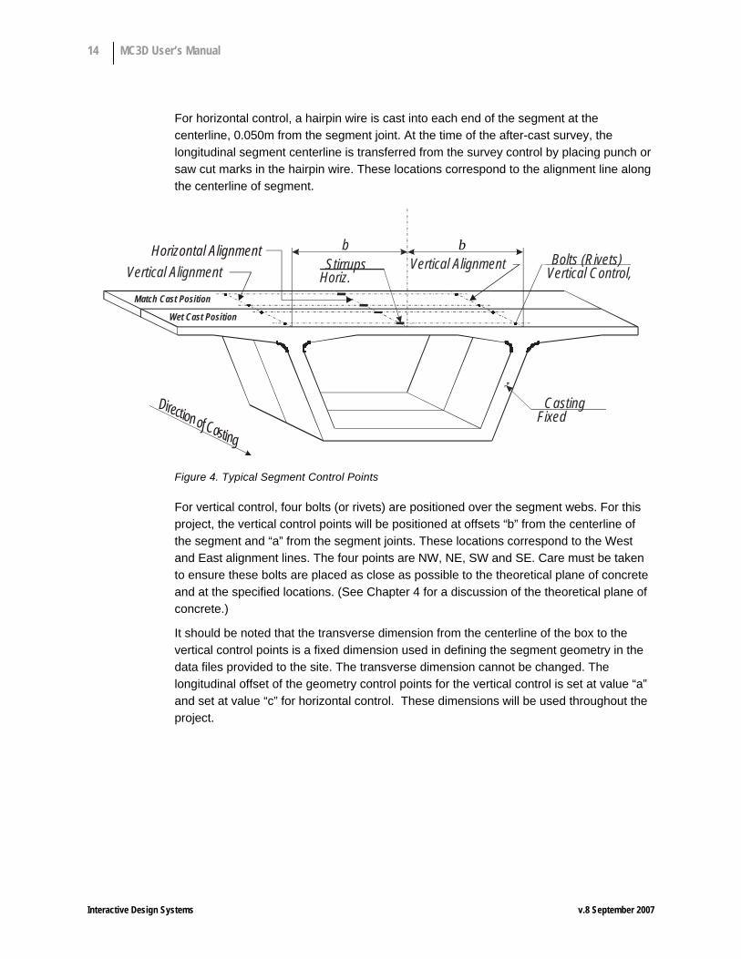
For horizontal control, a hairpin wire is cast into each end of the segment at the centerline, 0.050m from the segment joint. At the time of the after-cast survey, the longitudinal segment centerline is transferred from the survey control by placing punch or saw cut marks in the hairpin wire. These locations correspond to the alignment line along the centerline of segment.
b b
Casting Fixed
Match Cast Position Wet Cast Position
Bolts (Rivets) Vertical Control, Stirrups
Horiz. Vertical Alignment Vertical Alignment Horizontal Alignment
D i r e c t i o n o f C a s t i n g
Figure 4. Typical Segment Control Points
For vertical control, four bolts (or rivets) are positioned over the segment webs. For this project, the vertical control points will be positioned at offsets “b” from the centerline of the segment and “a” from the segment joints. These locations correspond to the West and East alignment lines. The four points are NW, NE, SW and SE. Care must be taken to ensure these bolts are placed as close as possible to the theoretical plane of concrete and at the specified locations. (See Chapter 4 for a discussion of the theoretical plane of concrete.)
It should be noted that the transverse dimension from the centerline of the box to the vertical control points is a fixed dimension used in defining the segment geometry in the data files provided to the site. The transverse dimension cannot be changed. The longitudinal offset of the geometry control points for the vertical control is set at value “a” and set at value “c” for horizontal control. These dimensions will be used throughout the project.

Chapter 4 — Match-Casting 15
Interactive Design Systems v.8 September 2007
Chapter 4 — Match-Casting Concept and Applicability
Theoretical Concrete: The system of vertical geometry control is based on a concept of a theoretical “Reference” plane. The base assumption is that a segment cast against a fixed bulkhead forms a top slab horizontal plane located at the elevation of the fixed bulkhead. The survey rivets, which cannot be placed perfectly in the reference plane, become measurements of the location of the plane rather than its actual definition. (See Example Figure 5).
Actual Concrete Surface(distorted for clarity)
0.050m 0.050m
Segment 1(Wet - Cast)
Theoretical ConcreteElevation 0.000m
Fixe
dBu
lkhea
d
Floa
ting
Bulkh
ead
Rivet B0.002m
Rivet A0.001m
AS-CAST VALUESRivet A: Rivet B: Theoretical plane of concrete is 0.002m below rivet
Theoretical plane of concrete is 0.001m below rivet
2.400m
Figure 5. Casting Starter Segment
As the actual concrete surface is slightly irregular and quite possibly skewed, the theoretical plane of concrete is not to be confused with the actual concrete surface.
The interpretation of Figure 5 is as follows:
Rivet N: Reference plane is 0.00lm below the rivet.
Rivet S: Reference plane is 0.002m below the rivet.
Once the reference plane has been established for a segment, the rivet readings can be used for defining set-up values for casting the next segment.
First, assume the camber diagram for a span has ordinates of 0.0m, 0.0m and 0.005m for the first three segment joints as measured in the local system. The wet-cast Segment 2 will be cast in a level position so that the match-cast Segment 1 will need to be positioned to obtain the angle break desired. (See Figure 6).

16 MC3D User’s Manual
Interactive Design Systems v.8 September 2007
Segment 1(Match - Cast)
Theoretical ConcreteElevation 0.000m
Fixe
dBu
lkhea
d
0.050mRivet B’0.007m
2.400m 3.150m
Rivet A’0.001m
DesiredCamber =0.005m Segment 2
(Wet - Cast)
Figure 6. Set-Up for Casting Segment 2
With the reference plane of Segment 1 to be located properly, the setup elevations for rivets North (N’) and South (S’) are calculated based on the ratio of their distance from the segment joints and their elevation with respect to the as-cast of concrete. Therefore, the following is obtained:
Rivet N’ = (0.050)/2.400 x (.005) + .001 = .001m
Rivet S’ = (2.350)/2.400 x (.005) + .002 = .007m
These are the setup rivet readings to create the desired camber. It is difficult to obtain these exact setup values during casting. Deviations occur, most notably from the small movements of the forms during concrete placement and slight inaccuracies in the actual setups. These deviations are the cause of unintentional cambers cast into the segments.
After casting of Segment 2, a new survey is performed and actual rivet readings are taken on the match-cast segment. This determines the actual as-cast location of the theoretical concrete of the match-cast segment, and is shown in Figure 7, below.
Segment 1(Match - Cast)
Theoretical ConcreteElevation 0.000m
Fixe
dBu
lkhea
d
0.050mRivet B0.008m
2.400m 3.150m
Rivet A0.002m
Segment 2(Wet - Cast)
Y1 Y2
Figure 7. Schematic Profile of As-Cast Survey

Chapter 4 — Match-Casting 17
Interactive Design Systems v.8 September 2007
The as-cast data for a segment when it is both wet cast and match cast is used to create the following locations of the reference planes:
Slope of Reference Plane for Match-Cast Segment
M = [(.008 - .002) – (.002m - .001)] / (2.40 – 2 x 0.05)m = 0.00217
Elevations at Segment Joints
y1 = (.008m - .002m) + .00217 x (.05m) = 0.006m
y2 = (.002m - .00lm) - .00217 x (.05m) = 0.001m
From this example, it is noted that the match-cast joint between the two segments is not at elevation 0.000m. This will create a step in the theoretical concrete lines representing the two segments. This does not indicate an actual step in the concrete surfaces between the two segments, but rather a discontinuity in the theoretical concrete lines.
The next step is to determine the actual geometry that has been cast into the segments. Figure 8 shows the two obtained theoretical concrete lines for the wet and match-cast segments.
Segment 1(Match - Cast)
0.050mRivet B0.008m
2.400m 3.150m
Rivet A0.002m
Segment 2(Wet - Cast)
Y3= 0.006m
Figure 8. As-Cast Survey w/Obtained C
Projecting Segment 1 theoretical concrete onto Segment 2 yields the following:
y3 = obtained camber
= 0.001 - [(0.006 -0.001)/2.40m] x 3.15m
= 0.001 – 0.007 = 0.006m (upward)
As each subsequent segment is wet-cast, rivets are placed to establish the reference plane of the segment. The above process of creating setup values for the match-cast segments, and then using the as-cast data to compute obtained cambers is repeated for each segment in the casting unit. For each segment, the previously obtained cambers are utilized in determining the setups.

18 MC3D User’s Manual
Interactive Design Systems v.8 September 2007
Horizontal geometry control follows a similar procedure, with a vertical plane defined by the punch marks in the centerline stirrups. The stirrup marks are established on the wet-cast segment during the after cast survey. All calculations for horizontal control are identical to the vertical control.
Twist Control: As previously noted, deviations from theoretical occur during match casting. The deviations are the direct result of not maintaining the exact setup position required of the match-cast segment. The consequences of this are two-fold. First, the vertical camber is affected, and second, a potential twist may occur.
Twist is defined as warping of the match-cast segment due to stress. It occurs when the relative relationship of rivet elevations change from the wet-cast to the match-cast positions. This twist can be attributed to the support restraints differing between the wet and match-cast conditions.
The geometric relationship between two segments is created during match casting. Consider the case that the match-cast segment has a stress induced twist. The geometric relationship between the two segments differs from the geometric relationship that would have occurred had the match-cast segment been stress free (i.e., no twist). The stress-free state is what will actually occur when the segments are erected. Therefore, to properly define the geometric relationship between two segments, they both must be in a stress-free state.
Twist correction is the elimination of the effects of stress-induced twist in the match-cast segment. It is accomplished by altering the after-cast survey rivet elevations of the match-cast segment at the South joint. MC3D incorporates the twist correction in its processing of the match cast data. The value of the twist correction is shown on the screen and included in the report form.

Chapter 4 — Match-Casting 19
Interactive Design Systems v.8 September 2007
Casting Cell and Bulkheads Figure 9 depicts the casting bed arrangement based on the local system of coordinates.
NOTE: Survey position and target may be reversed; “called north” always in orientation shown.
SESW S
NENW
Target
Matc
h-Ca
stW
et-C
ast
C SegmentLSurvey Position
Fixed Bulkhead
Vertical AlignmentEAST Line
Vertical AlignmentWEST Line
AlignmentStirrup, typ.
NE’
SE’
NW’
SW’
N
N’
S’
“Called NORTH”N
North End
North EndSouth End
South End
+ y
+ x
Dimension “B” Dimension “B”
“A”Rivet OffsetDimensions
“A”Hairpin OffsetDimension “C”
Figure 9. Casting Bed Orientation and Axes
Of critical importance is the proper orientation of the transverse offset (local y axis) in order to achieve the correct direction of curvature in plan view.
Starter Segment vs. Typical Segment MC3D makes a distinction between “Starter” segments and “Typical” segments. A casting-set is always made of a “Starter” segment (the first segment to be cast for the set), and a series of typical segments to be cast in succession with the short-call method.

20 MC3D User’s Manual
Interactive Design Systems v.8 September 2007
The Starter segment is usually cast in its own casting cell, and the back joint (South Joint) is orientated using a “Floating Bulkhead”. In other words, there is no “Match-Cast” segment to be used when pouring the Starter. MC3D recognizes this and has a specific input form for the starter segment. The third “tab” of the user interface (Set-Up & Survey) is where each segment “set-up” is displayed as well as all the fields for the recording of survey readings. The “Starter” input form is automatically displayed when you click the “Starter” segment (first segment in this release).
If you select other segments (typical), then the program automatically displays a “Typical” segment Set-Up and input fields for a typical segment (i.e. with Match-cast survey readings).
Survey and As-Cast - Method of Geometry Control Theoretical 3D coordinates of control points (3 points at the joints – East, West and Centerline) are used to create the local systems at the joints. The coordinates include any and all corrections for camber (inverse of final deflections). Local systems are located at each joint in the direction of casting (fixed bulkhead), and represent the casting-cell local coordinate system.
Starter Segment – The “starter” is the first segment cast. The fixed bulkhead is described above. The previous joint is arbitrarily named “the floating bulkhead” (it can be another segment already cast, and placed as match cast). For the “starter” segment, the setup consists of the 2 elevations of the floating bulkhead (East and West), the centerline (hairpin) offsets and the lengths on East and West lines.
Starter Segment Survey – The 4 bolt elevations, hairpin offsets, East and West lengths, and bulkhead movements are measured in the cell (local coordinates). From these local coordinates, we can compute the general “as-cast” coordinates of the starter segment.
Next Segment (Typical) – From the as-cast general coordinates of the “starter segment”, we can compute the relative position of the starter (now in match-cast position) and the next typical segment. This produces the match-cast “setup”, local coordinates of the match-cast in the cell system (of the wet-cast). To do so, we use a 3-dimensional matrix method, which produces a 3D translation vector and a 3D rotation matrix used to position the match cast. The “setup” of the match-cast segment indicates how the match cast should be positioned relative to the fixed bulkhead (cell system of coordinates).
Survey - Once the typical segment is cast (wet-cast), the 4 bolt elevations, hairpin offsets and length on centerline of both wet-cast and match-cast are surveyed, and produce the relative position of wet-cast and match-cast. From these measurements, we can compute the general as-cast coordinates of the typical segment (wet-cast). These coordinates indicate how the structure is actually cast as compared to the theoretical general coordinates.

Chapter 4 — Match-Casting 21
Interactive Design Systems v.8 September 2007
The as-cast coordinates of the wet-cast are used to produce its relative placement with the next typical segment. The methodology is the same as in 4) above, and produces the match-cast setup (4 elevations, 2 horizontal offsets and the length on center), by combining a 3D translation vector and a 3D rotation matrix. The cycle continues thereafter until completion of the entire casting-set.
NOTE
Note 1:
Bulkhead movements are accounted for, for starter segment as well as for the typical segments.
Note 2:
The “twist” values are given at every step. It is the responsibility of the engineer to adjust the setup to account for the twist.
Note 3:
This methodology may be tested by inputting arbitrary bolt elevations and offsets for the wet-cast, and assuming that the wet-cast and match-cast surveys are exactly equal to the proposed setup. The end result should be a perfect structure for which the as-cast coordinates are exactly equal to the theoretical general coordinates.
Note 4:
The distances a, b & c are assumed constant throughout the project. However, a and c (local offsets from the joints) may be re-defined specific per segment. The transverse offset “b” is considered constant and equal on both sides (East and West).
Note 5:
All computations are conducted with matrix algebra. The position of any point in 3D space is recognized as a “Translation” plus a “Rotation” characterized with a “Vector” and a 3x3 Rotation Matrix as follows:
⎪⎭
⎪⎬
⎫
⎪⎩
⎪⎨
⎧
⎥⎥⎥
⎦
⎤
⎢⎢⎢
⎣
⎡+
⎪⎭
⎪⎬
⎫
⎪⎩
⎪⎨
⎧=
⎪⎭
⎪⎬
⎫
⎪⎩
⎪⎨
⎧
i
i
i
i
i
i
zyx
rrrrrrrrr
ZYX
ZYX
333231
232221
131211
0
0
0
Or, when expressed in matrix form:
{ } { } [ ]{ }jiji xRXX += 0


Chapter 5 — Survey and As-Cast Coordinates 23
Interactive Design Systems v.8 September 2007
Chapter 5 — Survey and As-Cast Coordinates All survey operations should be performed by two independent surveys in order to provide critical checks of the results. A first survey (match cast set-up) is performed prior to segment casting to ensure the proper setup of the match-cast segment and the casting cell. After the segment is cast and initially cured, a second survey (after cast) is performed to check the actual as-cast position of the segment.
Two permanent horizontal reference points and a permanent bench mark should be set up for establishing and checking the surveying instrument position. The horizontal reference points should be established on line with the instrument mounting point. The permanent benchmark should be established at a location where it will not be disturbed by construction activities.
Control points for alignment, elevation and shape of the fixed bulkhead must be established prior to beginning casting operation and checked every time a survey on the adjoining segment is performed.
Starter Segment Form Set-up: The starter segment is always cast between two bulkheads (or the fixed bulkhead and another segment). The bulkheads are normal to the segment centerline and the top slab is in a level position. All geometric transitions are usually accommodated in the remaining segments of a casting-set.
Match-Cast Form Set-Up: Subsequent segments after the starter segment are cast using the fixed bulkhead at one end and the adjacent segment in the match-cast position at the other end for the floating bulkhead.
The match-cast set-up survey will be performed after the match-cast set-up values for both horizontal and vertical alignments have been calculated using the program MC3D. The procedure commences after the segment has been moved from the wet-cast to the match-cast position. A series of elevation shots are made along the East and West alignment lines to determine the existing altitude of the match-cast segment with respect to a benchmark to be used exclusively for the individual segment form. A comparison of this information is then made to the pre-calculated theoretical set-up values to determine which adjustment must be made to place the match-cast segment in its theoretically correct position.
The initial large adjustment of the match-cast segment is usually carried out using two jacks simultaneously to avoid inducing stress in the segment as a result of twisting. For example, a typical adjustment pattern may be executed as follows:
1. Adjust jacks under points NE and SE, to bring NE to its theoretical elevation.
2. Adjust jacks under points NW and SW, to bring NW to its theoretical elevation.
3. Adjust jacks under points SE and SW, to their theoretical elevations.

24 MC3D User’s Manual
Interactive Design Systems v.8 September 2007
The remaining minor elevation adjustments may be performed individually, as minimal twist will not have any significant effect on the segment. Match-cast segments should be set as closely as feasible to theoretical values generated from previous as-cast data.
After the segment has been aligned in the match-cast position, a twist calculation will be performed. A calculation worksheet is included on the survey form. The acceptable value twist is established as +/-0.0001m. If the twist is determined to be greater than this value after set-up, the segment shall be realigned to bring the twist into tolerance.
Using the theodolite, readings will be taken on the centerline stirrups along alignment line N-S to determine the horizontal attitude of the segment. Adjustment will be made to the soffit of the form to bring the segment to the required horizontal attitude, following which the form will be locked to maintain this position. The typical segments are all cast with a fixed bulkhead perpendicular to the centerline of the segment, and the match-cast end skewed, as necessary, to accommodate the horizontal curvature.
The overall wet-cast segment length will now be measured to insure its consistency within specified tolerances. Two measurements will be taken, one along each web line at the top deck. These values will be averaged, to determine the length of the segment on the centerline. If the new segment length is found to be out of tolerance, adjustments will be incorporated to correct it.
A final survey will be performed on the elevation points of the match-cast segment to ensure that no excessive vertical movement has taken place as a result of the horizontal or length adjustment. If any movement is detected, adjustment will be made immediately to correct the match-cast segment position.
When all segment set-up criteria have been satisfied and checked, the form will be left for the crews to close and tighten in preparation for concrete placement. During the form closing operations, it is not uncommon for the match-cast segment to have moved from its set-up position. For this reason, one final survey will be made to determine if the segment is still in satisfactory position to pour concrete. If the closing operations have moved the segment, adjustments will be made to return it to its theoretical position.
After-Cast Survey: The after-cast survey will constitute the most critical phase of the survey operation, as it will be from these values that the current segment elevations are calculated. The after-cast surveys should be performed in the early morning hours, prior to removal of the concrete forms. This time frame is absolutely necessary, as a true match cast/wet cast relationship must be determined prior to any separation of the two segments. The cooler morning temperature will also result in greater degree of accuracy in readings due to reduced visual thermal distortion.

Chapter 5 — Survey and As-Cast Coordinates 25
Interactive Design Systems v.8 September 2007
Independent Graphical Check: It is recommended that independent plots of the as-cast elevations and horizontal alignment be made and compared with the theoretical elevations and line. This provides the surveyor with a better understanding and a check of the MC3D program. The plots will graphically illustrate the deviations from the theoretical grade and line, the corrections needed to return the casting to the theoretical casting curve and any trends in the casting that can be corrected and avoided.


Chapter 6 — MC3D Program Overview 27
Interactive Design Systems v.8 September 2007
Chapter 6 — MC3D Program Overview The computer program MC3D allows the following:
• Input of a “casting-set” (a cantilever or a span), including number of segments, segment definition, joint definition and camber (final deflections at the end of construction with time effects).
• Match-Cast setup based on already cast geometry (As-Cast)
• Survey of match-cast and wet-cast markers, in order to compute as-cast coordinates
• Print-out of As-Cast coordinates
The program provides input and output through the use of screen forms, running in the Windows operating system (see attached screen shots). Joint coordinates and camber values are input in “Excel-compatible” grids that the user may edit.
Options MC3D uses a few options that are recorded in the registry. They are accessible via the Option Menu, and the Option Dialog Box is displayed:
The parameters given here dictate how MC3D interprets the input file with the joint general coordinates:
Starting and Ending Joints indicates if input lines must be skipped at the beginning and at the end of the file when reading joint coordinates.
Include Segment Names indicates that segment names are given for each joint following the joint number (the name is for the segment defined between the current joint and the next joint)

28 MC3D User’s Manual
Interactive Design Systems v.8 September 2007
Include Shim Angles indicates that angles values will be given in the match cast survey and accounted for in as-cast coordinates computations. This is an advanced feature that is not normally necessary (please contact IDS for detail about using this feature if needed)
Options are recorded in the registry and remain as defined for subsequent runs.

Chapter 7 — MC3D Program Architecture 29
Interactive Design Systems v.8 September 2007
Chapter 7 — MC3D Program Architecture The MC3D (Match-Cast 3D) program is a Windows application based on a series of tabbed forms. Each form is dedicated to the input and output of a specific sequence of the casting process. The tabs are:
• Project Definition
• Joint Coordinates
• Camber
• Starter Segment Set-Up
• Typical Segment Set-Up
• As-Cast Coordinates
• Reports
The information input and output in each tab is detailed below. Each form and its utilization are described in more detail in Chapter 8 – Working with MC3D.
MC3D application architecture is based on “Object Orientation”. The objects are “concrete segments” and “joints” and their relationships are captured in the object model. A “Project” is made of a collection of joints and segments (starter and typical) for which the relative geometry is known through a series of data sets, such as:
General Theoretical Coordinates
Local Theoretical Coordinates
Local As-Cast Coordinates (Survey)
Local Match-cast Coordinates (Survey)
General As-Cast Coordinates
The “data sets” as well as the “objects” are maintained by the application, through a process named “serialization” (the collections of objects are stored on the hard-disk for re-use). There is no need for a commercial database environment (such as MS-Access or SQL Server), and the projects are stored in their entirety on small disk files. Users may re-use existing projects by simply “opening” project files. On open, all joint theoretical and as-cast coordinates, segment relationships as well as past survey reading for all already cast segments are restored and ready to be used for the next cast.

30 MC3D User’s Manual
Interactive Design Systems v.8 September 2007
Project Definition Use this tab to input basic Project data, such as the Project Name, the “Casting Set” name, and the initial or full name of the author of the run. The casting-set is the set of general coordinates specific for the run. Coordinates must follow the orientation described in sections 2.3, 3.1 and 4.1.
Figure 10. Project Tab
In addition, you can input the default values for the a, b, c parameters:
• Value “a” is the longitudinal offset of the elevation bolts. This value is considered constant unless modified specifically for one or more segments.
• Value “b” is the transverse offset for the elevation bolts. It is considered constant on both sides (East and West) of the centerline for the entire casting-set
• Value “c” is the longitudinal offset of the centerline hairpins. This value is considered constant unless modified specifically for one or more segments.

Chapter 7 — MC3D Program Architecture 31
Interactive Design Systems v.8 September 2007
Joint Coordinates The general coordinates of the control points (elevation bolts and centerline hairpins) are given in an “Excel” spreadsheet like grid view. The coordinates given must follow the general orientation described in Chapters 3 and 4.
Figure 11. General Coordinates Tab and Grid
If you already have a spreadsheet file with the coordinates in the proper order, you may “cut-and-paste” the coordinates into this grid. If you have an ASCII (text) file containing the coordinates in the proper order, you may use the “Read File” button to open the file and read in the text content.
NORMALIZE Check Box
A “Normalize” check option may be used to extrapolate coordinates so the basic “b” dimension defined for the project is respected.
INCLUDE CAMBER Check Box
In addition, you may include the camber diagram (see below) by clicking the “Include Camber” option. Doing so will add the camber values to the display of vertical coordinate (Y) of all control points.

32 MC3D User’s Manual
Interactive Design Systems v.8 September 2007
PRINT Button
You may obtain a printed page with the “set-Up” values by pressing the Print button.
APPLY Button
By pressing the Apply button, you will record the survey as input in the form. On doing so, the program will compute the resulting “as-cast” coordinates of the bulkhead joint as well as the “set-up” for the next segment.
PREVIEW Button
You may use the “Preview” button to obtain a “print preview” of the coordinate table, which may be sent to the installed printer. As for all Windows application, you will need to have a printer driver installed in your Windows operating system. (See Microsoft documentation to install a new printer in Windows 9x or Windows NT/2K.)
Figure 12. Preview Window
The preview Dialog shows the computed values of the “B” constant on the East and West side for evaluation. Also, the program computes and prints the 3D “Bulkhead Angle”, i.e. the angle between the centerline of box and the bulkhead plane. In the Short-Cell method, this angle must be exactly 90 degrees.
The preview Dialog also shows the computed values of Cross-Slopes resulting from the control point coordinates, as well as the orientation of the Z axis. The Z axis orientation must be positive upward.

Chapter 7 — MC3D Program Architecture 33
Interactive Design Systems v.8 September 2007
Note: It is not possible to enter additional joint coordinates after starting to record the survey and initiating computations of match-cast setups and as-cast coordinates. If it becomes necessary to add segments to the casting set, you must restart recording the survey from the starter segment on.
Camber Diagram The camber diagram is made of the inverse of the long term vertical deflections computed to account for all long-term stress redistributions (creep, shrinkage and relaxation), obtained from a time-dependent analysis similar to the Bridge Designer II program (BD2) developed by Interactive Design Systems.
The camber values given must follow the joint orientation specific to the casting-set, and the joint number must correspond to the previously input joint coordinates. (See the Joint Coordinates section on page 31.)
If you already have a spreadsheet file with the camber values in the proper order, you may “cut-and-paste” the values into this grid. If you have an ASCII (text) file containing the camber values in the proper order, you may use the “Read File” button to open the file and read in the text content.
If joints coordinates are added after the survey recording has started, you must re-initialize and restart the survey recording from the beginning.

34 MC3D User’s Manual
Interactive Design Systems v.8 September 2007
Figure 13. Camber Tab and Grid
APLY Button
Pressing “Apply” will “add” the camber values to the joints definition. When camber values are added, they will automatically be accounted for in the theoretical geometry and set-up values (see segment Set-up and Survey).
Starter Segment Set-Up The “Starter” segment setup tab is different from the Typical Segment Set-Up. For the Starter segment, you need to position a “Floating” bulkhead, which can be a form or another segment previously cast. In all cases, the program provides the “Floating Bulkhead” set-up in the form of:
• East and West Control Elevations
• Centerline offset on the South side
• East and West Line required Lengths

Chapter 7 — MC3D Program Architecture 35
Interactive Design Systems v.8 September 2007
Figure 14. Starter Segment Set-Up & Survey Tab
If the “a” and/or “c” basic dimensions are changed for the Starter Segment, you may input the modified values in the “Bolt Offsets” input group. The edit fields are given for:
• aN : Value of “a” on the North Side (Elevation Bolts - North)
• aS : Value of “a” on the South Side (Elevation Bolts - South)
• cN : Value of “c” on the North Side (Centerline Pin - North)
• cS : Value of “c” on the South Side (Centerline Pin - South)
FLOATING BULKHEAD SET-UP
The program displays here the required elevations of the Floating Bulkhead. Based on the theoretical coordinates of the control points (including camber). The program simply computes the local coordinates of the back joint in the cell coordinate system.
The surveyor should provide this information for accurate placement of the floating bulkhead (or of another segment placed in match-cast position).
FLOATING BULKHEAD SURVEY
Input here the surveyed elevations and horizontal offsets of the control points on the floating bulkhead (or segment placed as match-cast)

36 MC3D User’s Manual
Interactive Design Systems v.8 September 2007
FIXED BULKHEAD SURVEY
Input here the surveyed displacements of the control points on the fixed bulkhead. These displacements (or bulkhead movements) will be used to correct the readings on the wet-cast bolts.
BOLT OFFSETS
You may here correct the values “a” and “c” given for the project, in case the bolts and hairpins are located at different offsets. Value “a” is the longitudinal distance from the bolts to the joint and value “c” Is the longitudinal distance from the hairpin to the joint. These values may be different on the “North” side and on the “South” side. However, they are considered identical on the “East” and “West” sides (for the bolts).
WET-CAST SURVEY
Input here the surveyed elevations of the bolts as placed on the wet-cast segment (starter segment) and horizontal offsets of the hairpins used for horizontal (offset) control.
PRINT Button
You may obtain a printed page with the “set-Up” values by pressing the Print button.
APPLY Button
By pressing the Apply button, you will record the survey as input in the form. On doing so, the program will compute the resulting “as-cast” coordinates of the bulkhead joint as well as the “set-up” for the next segment.
Please note that the “starter” segment is always placed in match-cast position based on the theoretical elevation of the south joint center control point. In other words, it is assumed that this segment will always be placed on the theoretical casting curve (theoretical profile plus camber), regardless of elevations & displacements of the floating bulkhead. The bolts as-cast survey readings, however are used to determine the “Set-Up” for the next segment pour.
Note: MC3D always assumes that the North joint (fixed bulkhead) of the Starter Segment is exactly placed on theoretical. Therefore any discrepancy on the Starter Segment Length is accounted for on the back joint (Floating Bulkhead), and there is not length correction for the first typical segment.

Chapter 7 — MC3D Program Architecture 37
Interactive Design Systems v.8 September 2007
Typical Segment Set-Up
Figure 15. Typical Segment Set-Up & Survey Tab
Survey MATCH-CAST SET-UP
The program displays here the required elevations of the Match-cast bolts. Based on the as-cast coordinates of the bolts and horizontal offsets surveyed when the segment was in wet-cast position. The program simply computes the local coordinates of the match-cast control points in the cell coordinate system.
The surveyor should use information for accurate placement of the match-cast segment. Great care should be taken not to induce distortion in placing the segment from wet-cast to match-cast position. If such a distortion occurs (known as “twist”), the program automatically corrects elevations as to eliminate this error from the survey (see discussion in Chapter 5).
MATCH-CAST SURVEY
Input here the surveyed elevations and horizontal offsets of the control points on the floating bulkhead (or segment placed as match-cast)

38 MC3D User’s Manual
Interactive Design Systems v.8 September 2007
FIXED BULKHEAD SURVEY
Input here the surveyed displacements of the control points on the fixed bulkhead. These displacements (or bulkhead movements) will be used to correct the readings on the wet-cast bolts.
BOLT OFFSETS
You may here correct the values “a” and “c” given for the project, in case the bolts and hairpins are located at different offsets. Value “a” is the longitudinal distance from bolts to the joint, value “c” Is the longitudinal distance from the hairpin to the joint. These values may be different on the “North” side and on the “South” side. However, they are considered identical on the “East” and “West” sides (for the bolts).
WET-CAST SURVEY
Input here the surveyed elevations of the bolts as placed on the wet-cast segment (starter segment) and horizontal offsets of the hairpins used for horizontal (offset) control.
MATCH-CAST TWIST
MC3D automatically evaluates the “twist”, defined as a distortion of match-cast segment, which can occur when the segment is moved from it’s original position in the cell, to it’s match-cast position. If a non-zero twist is detected (from the bolts surveyed elevations in match-cast position), it is displayed in the form for information, and a correction is applied half on the east bolt and half on the west bolt.
FIXED BULKHEAD MOVEMENTS
Input here the (hopefully small) differences in elevation and plan due to the fixed bulkhead possible movement. Please not that MC3D corrects the Wet-Cast Survey (elevations and horizontal offsets) with the values provided here. If non-zero values are provided for the fixed bulkhead movements DO NOT PRESS THE APPLY BUTTON MORE THAT ONCE. Doing so would apply the correction multiple times!
APPLY Button
By pressing the Apply button, you will record the survey as input in the form. On doing so, the program will compute the resulting “as-cast” coordinates of the bulkhead joint as well as the “set-up” for the next segment.
See note above regarding Fixed Bulkhead Movement.
If Bulkhead Movement corrections are given here, DO NOT use APPLY more than once, as this would re-apply the correction multiple times.

Chapter 7 — MC3D Program Architecture 39
Interactive Design Systems v.8 September 2007
PRINT Button
You may obtain a printed page with the “set-Up” values by pressing the Print button.
Figure 16. Print Preview of Match-Cast Set-Up

40 MC3D User’s Manual
Interactive Design Systems v.8 September 2007
As-Cast Coordinates
Figure 17. As-Cast Coordinates Tab
Once the survey readings are recorded for a segment, the program calculates the “as-cast” coordinates of the bulkhead joint control points, as well as the as-cast bolt and hairpin coordinates.
This information may be used to evaluate the accuracy of casting, by comparing the as-cast coordinates to the “Theoretical” coordinates, on this form.
SEGMENT COMBO-BOX
Select the segment for which you wish to display As-Cast coordinates
BULKHEAD JOINT THEORETICAL COORDINATES
The program displays here the x, y, z “theoretical” general coordinates of the control points on the “North” side of the segment (i.e. the fixed bulkhead side).
BULKHEAD JOINT AS-CAST COORDINATES
The program displays here the x, y, z “as-cast” general coordinates of the control points on the “North” side of the segment (i.e. the fixed bulkhead side), for comparison with the theoretical.

Chapter 7 — MC3D Program Architecture 41
Interactive Design Systems v.8 September 2007
BOLTS AND HAIRPINS COORDINATES
The program displays here the x, y, z “as-cast” general coordinates of the bolts and hairpins based on the surveyed elevations and offsets.
Figure 18. Match-Cast Setup Preview & Print

42 MC3D User’s Manual
Interactive Design Systems v.8 September 2007
Reports
Figure 19. Reports Tab
Once the survey readings are recorded for a segment, the program calculates the “as-cast” coordinates of the bulkhead joint control points, as well as the as-cast bolt and hairpin coordinates.
This information may be used to evaluate the accuracy of casting, by comparing the as-cast coordinates to the “Theoretical” coordinates, on this form.
AS-CAST VS THEORETICAL COORDINATES
Select this option to obtain a report showing the Theoretical and As-Cast Coordinates at all joints for the segments that are cast at this time. Click the Preview button to have MC3D display a preview – click Print to send to the printer.

Chapter 7 — MC3D Program Architecture 43
Interactive Design Systems v.8 September 2007
SEGMENT COMBO-BOX
Select a segment number in this combo box to obtain a report specific to the segment selected.
Figure 20. Report Print & Preview


Chapter 8 — Working with MC3D 45
Interactive Design Systems v.8 September 2007
Chapter 8 — Working with MC3D Installation and Registration
To install MC3D, simply follow the directions in the “Installation Notes”. The program installs on a PC as a standard “Windows” application. It registers file type “MC3D Documents” with the extension “.mc3”.
You may uninstall the application at any time, by using the “add/remove programs” icon, in Windows’ Control Panel.
MC3D is first installed as a 30 days trial license, and you need to obtain a registration key (also called “site key”) from IDS, or from the Distributor.
Getting Started Once the program is installed and properly registered, you can run one of the test files included in the delivery. When you are ready to utilize the program, the following procedure is suggested:
1. Gather general geometry for the project, and determine “casting sets”. In other words, the parts of the structures that will be cast as one unit. Casting Sets include a “Starter” segment (the first segment in the release), and a series of typical segments to be cast with the short-cell method.
2. Input the general coordinates (East, Center, West) of the control points for the casting-set. In order to do so, click the second tab “General Coordinates” and input the coordinate values in the grid, starting with the first joint (south joint of the starter segment).
Please review the assumptions outlined in section … for joint orientation. The “north” joint is always the “forward” joint in the direction of casting (it is also the fixed bulkhead joint). When facing the direction of casting (looking to the north joint), the control point on the left is the “West” control point, and the control point of the right is the “East” control point.
You may input the coordinate values directly in the grid, or “cut-and-paste” fro an Excel file, assuming that the values are organized in the proper order on rows and columns.
When all values are entered, make sure that the joints all have “identifiers”, and click “OK”. This will initialize your project, as well as create the segments corresponding to the joint values you have input.
3. Determine the constant values “a”, b””, and “c”. (See the Project Definition section in Chapter 7.)

46 MC3D User’s Manual
Interactive Design Systems v.8 September 2007
4. Select the first tab (Project) and fill-out the various fields defining the project. When you click the “OK” button, the program will generate the segment in the segment grid on the right of the form. In this grid, all segments will appear as “Not Cast”. Make sure you give each segment an identification or segment name) and click OK.
5. Input camber values in the Camber grid (third tab). The form shows 3 columns (DX, DY and DZ) in prevision of future implementations where 3D displacements may be input. In this release, only the DY value is given. It is the opposite of the vertical deflection obtain from long-term deflection analysis. If the camber values are obtained from BD2, they are directly usable as “DY” which represents the vertical nodal displacements.
6. Finally, when returning to the “General Coordinates” tab (second tab on the user interface). You may now click the “Include Camber” button, and the grid will display the vertical coordinates (Z values here) including the camber values given in the camber grid.
The Casting Cycle – Geometry Control and Survey After the General Coordinates are given, Segment Definitions and Camber values are recorded and the project initialized, the program is ready to record survey readings and compute as-cast geometry.
The casting cycle is as follows:
1. Run MC3D to produce the Set-Up for the Starter segment (floating bulkhead elevations (east and west), horizontal offset and 2 lengths (East line and West line) – print this information if needed.
2. Locate and adjust the floating bulkhead accordingly and proceed with pouring the starter segment.
3. Survey readings for:
a. The floating Bulkhead
b. The fixed Bulkhead
c. The bolts and hairpins for the Wet-Cast segment (Starter)
4. Record this information on the “Starter Segment” input form (Set-Up & Survey form for the first segment), and click OK. MC3D records the survey and computes the as-cast coordinates. The casting date for this segment is recorded.
5. Review As-Cast coordinates (As-Cast Coordinates tab is tab number 5). After reviewing this information, you are ready for the pouring of the next segment, a typical segment.

Chapter 8 — Working with MC3D 47
Interactive Design Systems v.8 September 2007
6. Click on the “Set-Up & Survey” tab again, and select the next segment in the “Wet-Cast” combo box. The form displays the fields for a typical segment, and shows the “Set-Up” values (4 elevations, 2 horizontal offsets and a length) – Print this information if needed.
7. Move the last segment from wet-cast position to match-cast position, trying to accommodate the required set-up described in Step 6. Make survey readings for wet-cast and match-cast bolts, as well as fixed bulkhead movements, and wet-cast segment length. Input these values in the form and click OK.
8. The “twist” value is displayed based on the relative elevations of the match-cast from what was measure for these bolts when the segment was in wet-cast position. The correction for a non-zero twist value is done on the match-cast South bolts, half on the East bolt and half on the West bolt.
9. Accept the twist corrections by clicking the OK button. The survey for the typical segment is recorded and the as-cast coordinates of the north joint as well as the general as-cast coordinates of bolts and hairpins are stored in memory. The date of casting is recorded so that the program knows that the segment has been cast and may be located in match-cast position for the next pour.
10. You may view the General As-Cast coordinates by clicking the “As-Cast” tab. The last segment number will be automatically selected, and as-cast coordinates will be displayed. You can then request a printout by clicking the Print button.
11. You may now repeat steps 5 to 10 for the next typical segments until you reach the end of the unit and the last typical segment of the casting-set.
12. At any time, you may go to the “Report” tab, and request various reports to be printed:
a. General Coordinates with and without camber values
b. Individual segment Set-Up and Survey readings
c. Individual segment As-Cast Coordinates
d. As-Cast vs. Theoretical Coordinates for all segments already cast


Chapter 9 — MC3D Reporting 49
Interactive Design Systems v.8 September 2007
Chapter 9 — MC3D Reporting Project Report
MC3D reporting features allow users to produce formatted reports to be sent to printers after a screen preview. This reporting capability is useful for several purposes:
• Check overall project definition, project parameters, general coordinates and camber
• Obtain printed data for each segment set-up and as-cast coordinates
• Overall as-cast coordinates
Each individual segment data may be previewed and printed from the “Set-Up and Survey” form as well as the “As-Cast Coordinates” form. In addition users may preview and print the same information from the “Report” tab where several printing options are available. (See the Reports section in Chapter 7.)
Casting Cell Reports Use the Preview button in the “Set-Up and Survey” tab view to Preview and Print each individual segment set-up. (See Figure 13 and the Survey section in Chapter 7.)


Chapter 10 — General Remarks 51
Interactive Design Systems v.8 September 2007
Chapter 10 — General Remarks Units
MC3D uses a “consistent” system of units. However, it is up to the user to make sure that the base parameters are expressed in units consistent with the general coordinates and camber. (See 3D Coordinates of Control Points and Survey Markers in Chapter 3 and Concept and Applicability in Chapter 4 for more information.)
Survey and As-Cast Accuracy Results accuracy is a direct function of the accuracy in input of the general coordinates. The general coordinates may be given with as many digits as required in the input grid. (See Joint Coordinates in Chapter 7.) When displaying the coordinates MC3D uses 6 digits after the decimal point.
Match-Cast setup elevations and offsets are provided with 4 decimals for maximum accuracy. Surveyors may or may not provide readings with this level of accuracy, but should always provide the maximum number of significant digits. As-Cast coordinates are also provided with 4 decimals.
Erection Control MC3D does not currently provide any functionality regarding erection control. However, all text displayed in Grids and Print Preview windows throughout the application are available for cut-and-paste into other programs or application. In addition, all grids are compatible with MS-Excel so you can easily export to this application for whatever formatting and plotting might be required for erection control.


