82
User Manual Reference/Professional Temperature Calibrator JOFRA RTC-156/157/158/159/250/700 A/B/C JOFRA PTC-125/155/350/660 A/B/C
| Date post: | 27-Mar-2018 |
| Category: |
Documents |
| Upload: | nguyendien |
| View: | 220 times |
| Download: | 2 times |
User ManualReference/Professional Temperature Calibrator
JOFRA RTC-156/157/158/159/250/700 A/B/CJOFRA PTC-125/155/350/660 A/B/C

User ManualReference/ Professional Temperature Calibrator
JOFRA RTC-156/157/158/159/250/700 A/B/CJOFRA PTC-125/155/350/660 A/B/C
Copyright 2012 AMETEK Denmark A/S

2 2013-11-18 128206 03

128206 03 2013-11-18 3
List of contents
1.0 Introduction ............................................................................ 5
1.1 List of equipment received ........................................................ 6
2.0 Safety instructions ................................................................. 8
3.0 Setting up the calibrator ...................................................... 15
3.1 Before use ................................................................................... 153.1.1 Setting up a dry-block calibrator .................................... 183.1.2 Setting up a liquid bath calibrator (RTC-158/250 only).. 20
3.2 During use ................................................................................... 24
3.3 Programming intelligent sensors ................................................ 25
3.4 Keyboard..................................................................................... 25
3.5 Main screen display .................................................................... 27
3.6 Standard connections ................................................................. 31
3.7 Input modules (B and C versions only)....................................... 32
3.8 Stability of temperature values ................................................... 33
4.0 Operating the Calibrator ...................................................... 34
4.1 Operating principle...................................................................... 344.1.1 Horizontal Menu............................................................. 354.1.2 Vertical Menu ................................................................. 354.4.3 Parameter Fields............................................................ 364.4.4 Working with lists ........................................................... 38
4.5 Starting the calibrator.................................................................. 40
4.6 Setting the temperature .............................................................. 40
4.7 Calibration (optional)................................................................... 414.7.1 Running a calibration ..................................................... 424.7.2 Viewing calibration results ............................................. 464.7.3 Displaying calibration information .................................. 474.7.4 Deleting workorders ....................................................... 49
4.8 Switch test menu ........................................................................ 504.8.1 Running a switch test..................................................... 504.8.2 Showing switch test results............................................ 52
4.9 Auto step menu........................................................................... 544.9.1 Running an Auto step calibration ................................... 544.9.2 Auto Step test results..................................................... 57
4.10 Sensor Setup menu .................................................................... 584.10.1 Setting the additional stability time (A version) .............. 584.10.2 Setting the parameters for TRUE – reference sensor (B
and C versions only) ...................................................... 594.10.3 Setting the parameters for DLC– dynamic load

4 2013-11-18 128206 03
compensation – RTC only (B and C versions only) ....... 614.10.4 Setting the parameters for SUT– Sensor under test (B
versions only) ................................................................. 614.10.5 Viewing the Reference and DLC data (B and C versions
only) ............................................................................... 64
4.11 Calibrator Setup menu................................................................ 654.11.1 Setting the temperature parameters .............................. 654.11.2 Setting the temperature resolution................................. 674.11.3 Setting the sound, volume and operating mode ............ 684.11.4 Setting calibration interval.............................................. 684.11.5 Changing the date and time........................................... 684.11.6 Choosing a language (optional) ..................................... 694.11.7 Saving a setup ............................................................... 694.11.8 Loading a setup ............................................................. 704.11.9 Resetting the instrument setup to factory defaults......... 704.11.10 Network Configuration (for service use only)................. 71
4.12 Selecting the stirrer speed (RTC-158/250 only) ........................ 72
4.13 Information Screen ..................................................................... 73
4.14 About the calibrator..................................................................... 74
5.0 Setting the mains voltage and replacing the main fuses... 75
6.0 After use................................................................................ 77
6.1 Storing and transporting the calibrators...................................... 77
6.2 Handling the dry-block calibrator ................................................ 78
6.3 Handling the liquid-bath calibrator (RTC- 158/250 only) ............ 79
128206 03 2013-11-18 5
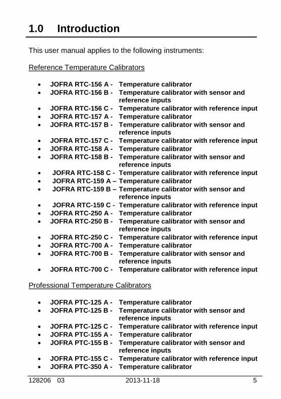
1.0 Introduction
This user manual applies to the following instruments:
Reference Temperature Calibrators
JOFRA RTC-156 A - Temperature calibrator JOFRA RTC-156 B - Temperature calibrator with sensor and
reference inputs JOFRA RTC-156 C - Temperature calibrator with reference input JOFRA RTC-157 A - Temperature calibrator JOFRA RTC-157 B - Temperature calibrator with sensor and
reference inputs JOFRA RTC-157 C - Temperature calibrator with reference input JOFRA RTC-158 A - Temperature calibrator JOFRA RTC-158 B - Temperature calibrator with sensor and
reference inputs JOFRA RTC-158 C - Temperature calibrator with reference input JOFRA RTC-159 A – Temperature calibrator JOFRA RTC-159 B – Temperature calibrator with sensor and
reference inputs JOFRA RTC-159 C - Temperature calibrator with reference input JOFRA RTC-250 A - Temperature calibrator JOFRA RTC-250 B - Temperature calibrator with sensor and
reference inputs JOFRA RTC-250 C - Temperature calibrator with reference input JOFRA RTC-700 A - Temperature calibrator JOFRA RTC-700 B - Temperature calibrator with sensor and
reference inputs JOFRA RTC-700 C - Temperature calibrator with reference input
Professional Temperature Calibrators
JOFRA PTC-125 A - Temperature calibrator JOFRA PTC-125 B - Temperature calibrator with sensor and
reference inputs JOFRA PTC-125 C - Temperature calibrator with reference input JOFRA PTC-155 A - Temperature calibrator JOFRA PTC-155 B - Temperature calibrator with sensor and
reference inputs JOFRA PTC-155 C - Temperature calibrator with reference input JOFRA PTC-350 A - Temperature calibrator

6 2013-11-18 128206 03
JOFRA PTC-350 B - Temperature calibrator with sensor andreference inputs
JOFRA PTC-350 C - Temperature calibrator with reference input JOFRA PTC-660 A - Temperature calibrator JOFRA PTC-660 B - Temperature calibrator with sensor and
reference inputs JOFRA PTC-660 C - Temperature calibrator with reference input
These instruments are temperature calibrators designed to calibratetemperature sensors and thermostats.
The RTC-156/157/159/700 A/B/C instruments and the PTC-series areall designed as dry-block calibrators, where as the RTC-158/250 A/B/Cinstruments are designed to be used both as dry-block calibrators andliquid baths.
Read this manual carefully before using the instrument and ensure thatall safety instructions and warnings are observed.
1.1 List of equipment received
When you receive the instrument, the following should be enclosed:
1 calibrator 1 mains cable 2 sets of test cables (2 black, 2 red –B versions only) 1 software package “JOFRACAL” and reference manual 1 USB cable 1 tool for insertion tube 1 traceable certificate (A versions) 2 traceable certificates (C versions) 3 traceable certificates (B versions) 1 set of silicone plugs for insulation plugs (RTC-
156/157/158/159/250 and PTC-125/155 only) 1 insulation collar (RTC-156 only) 1 protection shield (RTC-700 and PTC-660 only)
128206 03 2013-11-18 7
CautionDo not use the RTC-158 insulation plug (black POM) withthe RTC-250 instrument due to the risk of melting.
Always use the correct - yellow/brown PEEK - insulationplug with the RTC-250 instrument.
RTC-158/250 A/B/C only (liquid bath) - OPTIONAL
1 liquid bath kit consisting of :- 1 sensor basket- 2 lids for transportation / calibration- 1 stirring magnet- 1 stirring magnet remover- 1 liquid drainage syringe- 1 bottom shield- 1 silicone oil- 1 oil material safety data sheet

8 2013-11-18 128206 03
2.0 Safety instructions
Read this manual carefully before using theinstrument!In order to avoid any personal injuries and/or damage tothe instrument all safety instructions and warnings must beobserved.
The screen menus shown in this manual represent themenus displayed when using a B-version.
Disposal – WEEE Directive
These calibrators contain Electrical and Electronic circuitsand must be recycled or disposed of properly (inaccordance with the WEEE Directive 2002/96/EC).
Warning
About the use:
The calibrator must not be used for any purposes otherthan those described in this manual, as it might cause ahazard.
The calibrator has been designed for indoor use onlyand is not to be used in wet locations.
The calibrator is not to be used in hazardous areas,where vapour or gas leaks, etc. may constitute adanger of explosion.
The calibrator is not designed for operation in altitudesabove 2000 meters.
The calibrator is a CLASS I product and must beconnected to a mains outlet with a protective earthconnection. Ensure the ground connection of thecalibrator is properly connected to the protective earthbefore switching on the calibrator. Always use a mainspower cable with a mains plug that connects to theprotective earth.
128206 03 2013-11-18 9
To ensure the connection to protective earth anyextension cord used must also have a protective earthconductor.
Only use a mains power cord with a current rating asspecified by the calibrator and which is approved for thevoltage and plug configuration in your area.
Before switching on the calibrator make sure that it isset to the voltage of the mains electricity supply.
Always position the calibrator to enable easy and quickdisconnection of the power source (mains inlet socket).
The calibrator must be kept free within an area of 20cm on all sides and 1 metre above the calibrator due tofire hazard.
Never use heat transfer fluids such as silicone, oil,paste, etc. in the dry-block calibrators. These fluids maypenetrate the calibrator and cause electrical hazard,damage or create poisonous fumes.
The calibrator must be switched off before any attemptto service the instrument is made. There are no userserviceable parts inside the calibrator.
When cleaning the well or the insertion tube,REMEMBER to wear goggles when using compressedair in the dry-block calibrator and cleaning oil in theliquid bath calibrator.
Use protection shield when calibrating at hightemperatures (RTC-700 and PTC-660)
The RTC-159 and PTC-125 contains R-1270 and R-704 under pressure. The calibrator must under noconditions be stored at ambient temperatures above50°C ( 122°F) or operated at ambient temperaturesabove 40C (104F). Doing so may cause a hazard.
About the front panel:
For B and C versions only, the sockets on the inputmodule must NEVER be connected to voltagesexceeding 30V with reference to ground.
Thermostats must not be connected to any othervoltage sources during test.
10 2013-11-18 128206 03
About insertion tubes, insulation plugs, well andsensor:
Never leave hot insertion tubes which have beenremoved from the calibrator unsupervised – they mayconstitute a fire hazard or personal injury.
If you intend to store the calibrator in the optionalcarrying case after use, you must ensure that theinstrument has cooled down to a temperaturebelow 100°C/212°F before placing it in the carryingcase.
Never place a hot insertion tube in the optional carryingcase.
About the fuses:
The fuse box must not be removed from the powercontrol switch until the mains cable has beendisconnected.
The two main fuses must have the specified currentand voltage rating and be of the specified type. Theuse of makeshift fuses and the short-circuiting of fuseholders are prohibited and may cause a hazard.
About the liquid bath (RTC-158/250 A/B/C only):
For liquid bath ensure that the sensor is absolutelyclean and dry as a few drops of water in the well (liquidbaths) might cause a steam explosion.
Do not pour cold fluid into a hot well – it might causean explosion.
AMETEK Denmark A/S does not take anyresponsibility, if the well is filled with other fluids thanthose recommended.
Liquid baths should only be operated by trainedpersonal.
Heat transfer fluids must only be used in calibratorsprepared as a liquid bath. If these fluids are heatedabove specified temperature they will create noxious ortoxic fumes. Proper ventilation must be used.
128206 03 2013-11-18 11
To avoid hazards from treating fluids in a wrongmanner, always reduce the "Max. SET-temperatureallowed” in the CALIBRATOR SETUP MENU accordingto the specifications of the fluid to be used.If using a calibrator outside of the fluids specificationsthere is a risk of fire hazards, personal Injury orchemical release.By reducing the "Max. SET-temperature allowed”, thecalibrator cannot be used outside this temperaturerange.Be aware of the flash point, the boiling point and otherfluid properties applicable to the usage when setting theMax. SET-temperature. Read the MSDS (MaterialSafety Data Sheet) of the liquid before use.
Always remove the liquid from the calibrator beforetransportation.
Product information on the fluid must be carefullyinvestigated before use.
Do not handle hot fluid.
If the oil is heated beyond the flash point, it mayconstitute a fire hazard.
Do not pour water or any other fluids into a bath filledwith hot oil, because only a few drops of water mightcause a steam explosion, if poured into above 100°Chot oil.
Do not under any circumstances pour water on burningoil. It might cause a dangerous steam explosion.
Caution – Hot surfaceThis symbol is engraved in the grid plate.
Do not touch the grid plate, the well or the insertiontube when the calibrator is heating up – they may bevery hot and cause burns.
Do not touch the lid or the spill tray when the calibratoris heating up – they may be very hot and cause burns(RTC-158/250 A/B/C only).

12 2013-11-18 128206 03
Do not touch the tip of the sensor when it is removedfrom the insertion tube/well – it may be very hot andcause burns.
Do not touch the handle of the calibrator during use – itmay be very hot and cause burns.
Over 50°C/122°F
If the calibrator has been heated up to temperaturesabove 50°C/122°F, you must wait until the instrumentreaches a temperature below 50°C/122°F before youswitch it off.
Do not remove the insert from the calibrator before theinsert has cooled down to less than 50°C/122°F.
Caution – Cold surface
Below 0°C/32°F
(applies only to the RTC-156/157/158/159 A/B/C andPTC-125/155 A/B/C models)
Do not touch the well or insertion tube when these arebelow 0°C/32°F - they might create frostbite.
If the calibrator has reached a temperature below0°C/32°F, ice crystals may form on the insertion tubeand on the well. This, in turn, may cause the materialsurfaces to oxidize.To prevent this from happening, the insertion tube andthe well must be dried. This is done by heating up thecalibrator to min. 100°C/212°F until all water left hasevaporated.Remove the insulation plug while heating up.
It is very important that humidity in the well and insertiontube is removed to prevent corrosion and frostexpansion damages.
128206 03 2013-11-18 13
Caution…
About the use:
Do not use the instrument if the internal fan is out oforder.
Before cleaning the calibrator, you must switch it off,allow it to cool down and remove all cables.
About the liquid bath (RTC-158/250 A/B/C only):
Be careful not to overfill the well with oil.
Avoid getting silicone oil on the clothes. It is impossibleto wash off.
The oil level rises several centimetres when thetemperature is rising. Please read instructions insection 3.1.2 about oil level. To stop overflow switch offthe main power and the oil level will decrease whencooled down.
Carefully wipe off all silicone oil from the sensor undertest to avoid spreading of the silicone oil.
Be careful to select the right oil for the right task. Usingother than the recommended oils might cause damageto the calibrator or degrade the performance.
Remove excess hot fluid with the outmost care, as itmight be very hot.
Do not attempt to remove hot fluid with the liquiddrainage tube, as it might melt.
About the well, insertion tube and sensor:
The well and the insertion tube must be clean and drybefore use.
Do not pour any form of liquids into the well. It mightdamage the well or cause a hazard.
Do not use any alkali, acid or ionic fluids in thealuminium well as it might be damaged.
Scratches and other damage to the insertion tubesshould be avoided by storing the insertion tubescarefully when not in use.
The insertion tube must never be forced into the well.
14 2013-11-18 128206 03
The well could be damaged as a result, and theinsertion tube may get stuck.
Before using new insertion tubes for the calibration, theinsertion tubes must be heated up to maximumtemperature – 250°C (482°F) / 700°C (1292°F) (RTC-250/700 A/B/C only) and 350°C (662°F) / 660°C(1220°F) (PTC-350/660 A/B/C only) - for a period ofminimum 30 minutes.
The insertion tube must always be removed from thecalibrator after use.The humidity in the air may cause corrosion oxidationon the insertion tube inside the instrument. There is arisk that the insertion tube may get stuck if this isallowed to happen.
If the calibrator is to be transported, the insertion tubemust be removed from the well to avoid damage to theinstrument.
The tip of the sensor should rest at the bottom of thesensor basket for optimum results (liquid baths only).
Be careful not to submerge the handle or wire inlet ofthe sensor-under-test in the fluid, as this might damagethe sensor (liquid baths only).
Note…The product liability only applies if the instrument issubject to a manufacturing defect. This liability becomesvoid if the user fails to follow the instructions set out in thismanual or uses unauthorized spare parts.
128206 03 2013-11-18 15
3.0 Setting up the calibrator
3.1 Before use
The RTC/PTC-B-versions have a precision reference input. To achievethe high precision, a set of sensor coefficients relating to the specificsensor must be present in the RTC/PTC. Before use of the RTC/PTC,ensure that the correct coefficients in the RTC/PTC are equal to thosefrom the sensors calibration certificate. This is done with the includedPC software JOFRACAL. Please read how to do in the chapter“Reference Sensors” in the JOFRACAL user manual.
Warning The calibrator must not be used for any purposes other
than those described in this manual, as it might cause ahazard.
The calibrator has been designed for indoor use onlyand is not to be used in wet locations.
The calibrator is not to be used in hazardous areas,where vapour or gas leaks, etc. may constitute a dangerof explosion.
The calibrator is not designed for operation in altitudesabove 2000 meters.
The calibrator is a CLASS I product and must beconnected to a mains outlet with a protective earthconnection. Ensure the ground connection of thecalibrator is properly connected to the protective earthbefore switching on the calibrator. Always use a mainspower cable with a mains plug that connects to theprotective earth.
To ensure the connection to protective earth anyextension cord used must also have a protective earthconductor.
Only use a mains power cord with a current rating asspecified by the calibrator and which is approved for thevoltage and plug configuration in your area.

16 2013-11-18 128206 03
Before switching on the calibrator make sure that it isset to the voltage of the mains electricity supply.
Always position the calibrator to enable easy and quickdisconnection of the power source (mains inlet socket).
The calibrator must be kept free within an area of 20cm on all sides and 1 metre above the calibrator due tofire hazard.
Never use heat transfer fluids such as silicone, oil,paste, etc. in the dry-block calibrators. These fluids maypenetrate the calibrator and cause electrical hazard,damage or create poisonous fumes.
Use protection shield when calibrating at hightemperatures (RTC-700 and PTC-660)
The RTC-159 and PTC-125 contains R-1270 and R-704under pressure. The calibrator must under noconditions be stored at ambient temperatures above50°C ( 122°F) or operated at ambient temperaturesabove 40C (104F). Doing so may cause a hazard.
About the front panel:
For B and C versions only, the sockets on the inputmodule must NEVER be connected to voltagesexceeding 30V with reference to ground. Thermostatsmust not be connected to any other voltage sourcesduring test.
About the liquid bath (RTC-158/250 A/B/C only):
For liquid bath ensure that the sensor is absolutelyclean and dry as a few drops of water in the well (liquidbaths) might cause a steam explosion.
Do not pour cold fluid into a hot well – it might causean explosion.
AMETEK Denmark A/S does not take anyresponsibility, if the well is filled with other fluids thanthose recommended.
Liquid baths should only be operated by trainedpersonal.
Heat transfer fluids must only be used in calibratorsprepared as a liquid bath. If these fluids are heated
128206 03 2013-11-18 17
above specified temperature they will create noxious ortoxic fumes. Proper ventilation must be used.
To avoid hazards from treating fluids in a wrongmanner, always reduce the "Max. SET-temperatureallowed” in the CALIBRATOR SETUP MENU accordingto the specifications of the fluid to be used.If using a calibrator outside of the fluids specificationsthere is a risk of fire hazards, personal Injury orchemical release.By reducing the "Max. SET-temperature allowed”, thecalibrator cannot be used outside this temperaturerange.Be aware of the flash point, the boiling point and otherfluid properties applicable to the usage when setting theMax. SET-temperature. Read the MSDS (MaterialSafety Data Sheet) of the liquid before use.
Product information on the fluid must be carefullyinvestigated before use.
Do not handle hot fluid.
If the oil is heated beyond the flash point, it mayconstitute a fire hazard.
Do not pour water or any other fluids into a bath filledwith hot oil, because only a few drops of water mightcause a steam explosion, if poured into above 100°Chot oil.
Do not under any circumstances pour water on burningoil. It might cause a dangerous steam explosion.
Note…The instrument must not be exposed to draughts.

18 2013-11-18 128206 03
3.1.1 Setting up a dry-block calibrator
Fig. 1a – This image shows the RTC-model
Follow the instructions below before using the calibrator (cf. fig. 1a)
Warning
Always position the calibrator to enable easy and quickdisconnection of the power source (mains inlet socket).
1. Place the calibrator on an even horizontal surface where youintend to use it (pos. 1).
128206 03 2013-11-18 19
Caution…
Do not use the instrument if the internal fan is out oforder.
The well must be clean before use.
2. Ensure a free supply of air to the internal fan located at thebottom of the instrument (pos. 2)The area around the calibrator should be free of draught, dirt,flammable substances, etc.
3. Check that the voltage setting, shown on the power controlswitch (pos. 3), is identical to the mains voltage used.
4. Check that the earth connection for the instrument is presentand attach the cable below the power control switch (pos. 4).
5.
6.
Select an insertion tube (pos. 5) with a boring diametermatching the sensor (pos. 6) to be calibrated. Ensure thatboth the well and the insertion tube are clean. Insert the tubeinto the well.
Place the sensor (pos. 6) and the reference sensor – ifavailable (pos. 7) in the insertion tube (pos. 5) as shown in fig.1a.

20 2013-11-18 128206 03
3.1.2 Setting up a liquid bath calibrator (RTC-158/250 only)
Fig. 1b
Follow the instructions below before using the calibrator (cf. fig. 1b)
Warning
Always position the calibrator to enable easy and quickdisconnection of the power source (mains inlet socket).
1. Place the calibrator on an even horizontal surface where youintend to use it. Place it in a way that will minimize the risk oftilting (pos. 1). It is recommended to cover the surface with adisposable cover in order to protect the surface against thesilicone oil, if spilled.
1
2
3
9
10
4
5
6
8
7
11
Oil
128206 03 2013-11-18 21
It is also recommendable to have a sufficient amount ofdisposable paper towels within reach.
Caution…
Do not use the instrument if the internal fan is out oforder. Ensure a free supply of air to the internal fanlocated at the bottom of the instrument (pos. 2).
The well must be clean before use.
2.
3.
The area around the calibrator should be free of draught, dirt,flammable substances, etc.
Place the parts from the liquid bath kit in the well in thefollowing order:
Bottom shield (pos. 3) – It is very important that thebottom shield is placed in the well before any calibrationis attempted, as the bottom shield protects the well frombeing damaged during calibration.
Stirring magnet (pos. 4) – It is very important that thestirring magnet is in place and spinning before anycalibration is attempted. The stirring magnet ensuresminimum temperature gradient in the fluid. The magnetsteflon cover will over time be worn down, leaving themagnet flat on one side. This will reduce the spinningability. A magnet with a flat side must therefore bereplaced.
Sensor basket (pos. 5) – It is very important to placethe sensor basket in the well, as it ensures that thesensors encounter maximum temperature stability andensures that the stirring magnet is not blocked.
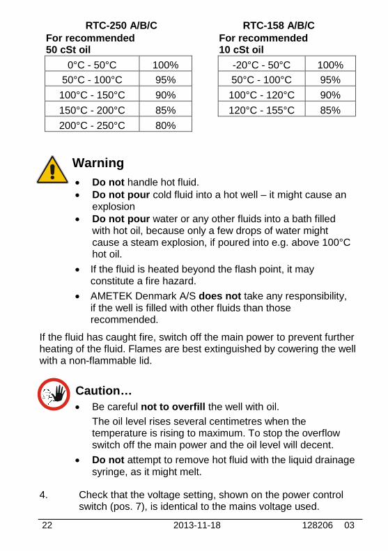
Silicone oil (pos. 6) – Fill the well with oil according tothe tables of recommended oil volume listed in thetables below. The recommended volumes must beadjusted to the actual job.The sensor basket (pos. 4) is marked with an optimumfluid level mark (100%). When filling the well with fluid andplacing the sensors, this mark must never be exceeded.
22 2013-11-18 128206 03
RTC-250 A/B/C RTC-158 A/B/CFor recommended50 cSt oil
For recommended10 cSt oil
0°C - 50°C 100% -20°C - 50°C 100%
50°C - 100°C 95% 50°C - 100°C 95%
100°C - 150°C 90% 100°C - 120°C 90%
150°C - 200°C 85% 120°C - 155°C 85%
200°C - 250°C 80%
Warning
Do not handle hot fluid. Do not pour cold fluid into a hot well – it might cause an
explosion Do not pour water or any other fluids into a bath filled
with hot oil, because only a few drops of water mightcause a steam explosion, if poured into e.g. above 100°Chot oil.
If the fluid is heated beyond the flash point, it mayconstitute a fire hazard.
AMETEK Denmark A/S does not take any responsibility,if the well is filled with other fluids than thoserecommended.
If the fluid has caught fire, switch off the main power to prevent furtherheating of the fluid. Flames are best extinguished by cowering the wellwith a non-flammable lid.
Caution…
Be careful not to overfill the well with oil.
The oil level rises several centimetres when thetemperature is rising to maximum. To stop the overflowswitch off the main power and the oil level will decent.
Do not attempt to remove hot fluid with the liquid drainagesyringe, as it might melt.
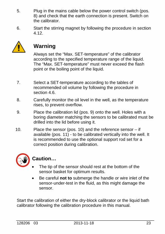
4. Check that the voltage setting, shown on the power controlswitch (pos. 7), is identical to the mains voltage used.
128206 03 2013-11-18 23
5. Plug in the mains cable below the power control switch (pos.8) and check that the earth connection is present. Switch onthe calibrator.
6. Start the stirring magnet by following the procedure in section4.12.
Warning
Always set the “Max. SET-temperature” of the calibratoraccording to the specified temperature range of the liquid.The “Max. SET-temperature” must never exceed the flashpoint or the boiling point of the liquid.
7. Select a SET-temperature according to the tables ofrecommended oil volume by following the procedure insection 4.6.
8. Carefully monitor the oil level in the well, as the temperaturerises, to prevent overflow.
9. Place the calibration lid (pos. 9) onto the well. Holes with aboring diameter matching the sensors to be calibrated must bedrilled into the lid before using it.
10. Place the sensor (pos. 10) and the reference sensor – ifavailable (pos. 11) - to be calibrated vertically into the well. Itis recommended to use the optional support rod set for acorrect position during calibration.
Caution…
The tip of the sensor should rest at the bottom of thesensor basket for optimum results.
Be careful not to submerge the handle or wire inlet of thesensor-under-test in the fluid, as this might damage thesensor.
Start the calibration of either the dry-block calibrator or the liquid bathcalibrator following the calibration procedure in this manual.
24 2013-11-18
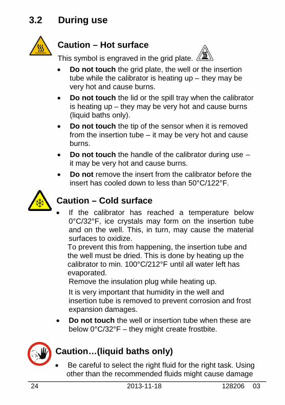
3.2 During use
Caution – Hot surface
This symbol is engraved in the grid plate.
Do not touch the grid plate, the well or the insertiontube while the calibrator is heating up – they may bevery hot and cause burns.
Do not touch the lid or the spill tray when the calibratoris heating up – they may be very hot and cause burns(liquid baths only).
Do not touch the tip of the sensor when it is removedfrom the insertion tube – it may be very hotburns.
Do not touch the handle of the calibrator during useit may be very hot and cause burns.
Do not remove the insert from the calibrator befoinsert has cooled down to less than 50°C/122°F.
Caution – Cold surface
If the calibrator has reached a temperature below0°C/32°F, ice crystals may form on the insertion tubeand on the well. This, in turn, may cause the materialsurfaces to oxidize.To prevent this from happening, the insertion tube andthe well must be dried. This is done by heating up thecalibrator to min. 100°C/212°F until all water left hasevaporated.Remove the insulation plug while heating up.
It is very important that humidity in the well andinsertion tube is removed to prevent corrosion and frostexpansion damages.
Do not touch the well or insertion tube when these arebelow 0°C/32°F – they might create frostbite.
Caution…(liquid baths only)
Be careful to select the right fluid for the right task. Usingother than the recommended fluids might cause damage
128206 03
the grid plate, the well or the insertionthey may be
the lid or the spill tray when the calibratorand cause burns
the tip of the sensor when it is removedit may be very hot and cause
the handle of the calibrator during use –
remove the insert from the calibrator before theinsert has cooled down to less than 50°C/122°F.
If the calibrator has reached a temperature below0°C/32°F, ice crystals may form on the insertion tubeand on the well. This, in turn, may cause the material
To prevent this from happening, the insertion tube andthe well must be dried. This is done by heating up the
until all water left has
Remove the insulation plug while heating up.
hat humidity in the well andinsertion tube is removed to prevent corrosion and frost
the well or insertion tube when these arecreate frostbite.
Be careful to select the right fluid for the right task. Usingother than the recommended fluids might cause damage
128206 03 2013-11-18 25
to the calibrator or degrade the performance.
It is vital that the stirring magnet is in place and spinningbefore any calibration attempts. The spinning magnetensures optimum temperature homogeneity in the oil.
It is strongly recommended to leave the lid on duringcalibration. Calibration without the lid may affect thetemperature stability and homogeneity.
When heated to high temperatures, the liquid bathcalibrator should be placed under a exhaust hood toremove any vapors given off by the oil.
3.3 Programming intelligent sensors
Use the configuration software CON050 supplied with RTC/PTC toprogram and to update calibration information in intelligent sensors.
For instructions read the software manual for CON050.
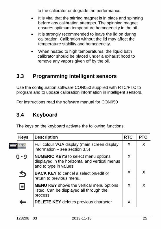
3.4 Keyboard
The keys on the keyboard activate the following functions:
Keys Description RTC PTC
Full colour VGA display (main screen displayinformation – see section 3.5)
M X X
NUMERIC KEYS to select menu optionsdisplayed in the horizontal and vertical menusand to type in values
X
BACK KEY to cancel a selection/edit orreturn to previous menu.
X X
MENU KEY shows the vertical menu optionslisted. Can be displayed all through theprocess
X X
DELETE KEY deletes previous character X

26 2013-11-18 128206 03
Keys Description RTC PTC
ENTER KEY accepts selected options orentered values. When a value is entered withthe ENTER KEY the cursor selects the nextvalue field in the list.
X
ARROW KEYS have different functionsdepending on the mode of operation.
In navigation mode, they move the cursor inthe desired direction.
In edit mode they roll in the list of options or ifentering a number, the ARROW left andARROW right move the cursor one characterin the desired direction
X X
ACTION KEY opens and closes edit fields ora menu button. The action key also acceptsthe selected option or entered value.
ACTION KEY and ENTER KEY
ACTION KEY opens and closes edit fields ora menu button. The action key also acceptsthe selected option or entered value.
ENTER KEY accepts selected options orentered values. When a value is entered withthe ENTER KEY the cursor
X
X
128206 03 2013-11-18 27
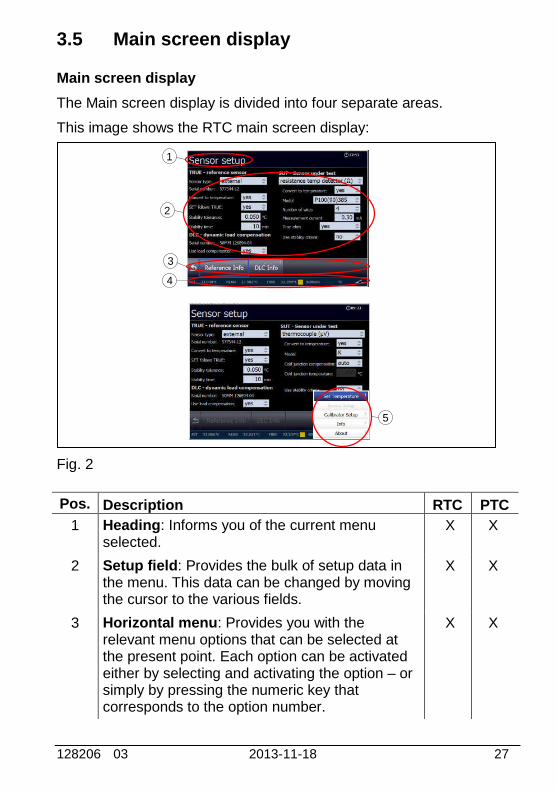
3.5 Main screen display
Main screen display
The Main screen display is divided into four separate areas.
This image shows the RTC main screen display:
Fig. 2
Pos. Description RTC PTC
1 Heading: Informs you of the current menuselected.
X X
2 Setup field: Provides the bulk of setup data inthe menu. This data can be changed by movingthe cursor to the various fields.
X X
3 Horizontal menu: Provides you with therelevant menu options that can be selected atthe present point. Each option can be activatedeither by selecting and activating the option – orsimply by pressing the numeric key thatcorresponds to the option number.
X X
1
2
3
4
5
28 2013-11-18 128206 03
Pos. Description RTC PTC
4 Readings: This reading line is always visibleand informs you of the current readings.
X X
5 Vertical menu: This menu can be activatedthroughout the entire calibration. The menu canbe switched on and off in all stages of operatingthe calibrator.
X X
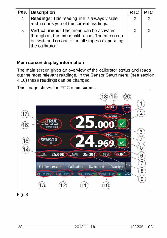
Main screen display information
The main screen gives an overview of the calibrator status and readsout the most relevant readings. In the Sensor Setup menu (see section4.10) these readings can be changed.
This image shows the RTC main screen.
Fig. 3

128206 03 2013-11-18 29
Pos. Description RTC PTC
1
2
3
Resistance of external reference sensor whenexternal reference sensor is selected asTRUE. (Optional - PTC)
Stability indicator displays the status of theTrue temperature stability.
True temperature reading. Can be either theinternal reference sensor or an externalreference sensor.
X
X
X
X
X
X
4
5
6
Sensor under test value in ohm/mV/mA.(Optional - PTC)
Sensor Under Test Stability indicator. IfSensor under Test stability criteria is selected,a symbol will indicate the stability of thesensor under test as well as the True sensor.
SENSOR. Sensor Under Test value.
X
X
X
X
X
X
7 DLC sensor reading. Displays the measuredtemperature load of the insert –if the loadcompensation is active, the DLC system willcontrol this value towards 0.00°C.
X
8 DLC compensation activated. The iconindicates, that the Dynamic LoadCompensation function is active
X
9 READ value. The internal reference is alwaysdisplayed as READ value.
X X
10
11
12
13
14
15
16
17
SENSOR value always visible.
TRUE value always visible.
READ value always visible.
SET reading always visible.
SET temperature.
Sensor Under Test Type.
Set follows True activated.
Reference Sensor Info.
X
X
X
X
X
X
X
X
X
X
X
X
X
X
X
X
30 2013-11-18 128206 03
Pos. Description RTC PTC
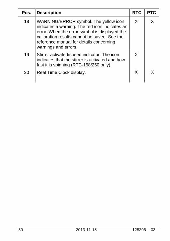
18 WARNING/ERROR symbol. The yellow iconindicates a warning. The red icon indicates anerror. When the error symbol is displayed thecalibration results cannot be saved. See thereference manual for details concerningwarnings and errors.
X X
19
20
Stirrer activated/speed indicator. The iconindicates that the stirrer is activated and howfast it is spinning (RTC-158/250 only).
Real Time Clock display.
X
X X
128206 03 2013-11-18 31
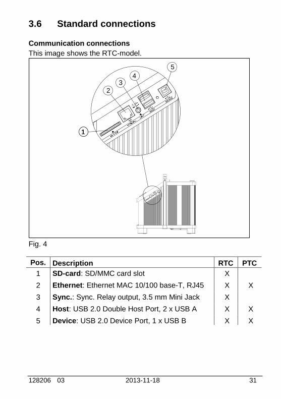
3.6 Standard connections
Communication connections
This image shows the RTC-model.
Fig. 4
Pos. Description RTC PTC
1 SD-card: SD/MMC card slot X
2 Ethernet: Ethernet MAC 10/100 base-T, RJ45 X X
3 Sync.: Sync. Relay output, 3.5 mm Mini Jack X
4 Host: USB 2.0 Double Host Port, 2 x USB A X X
5 Device: USB 2.0 Device Port, 1 x USB B X X
HOST
DEVICE
HOST
DEVICE
11
23
4
5

32 2013-11-18 128206 03
3.7 Input modules (B and C versions only)
Warning
The input terminals must NEVER be connected tovoltages exceeding 30V with reference to ground.
Description of sockets for external connections
This image shows the RTC-model.
Fig. 5
Pos. Description RTC PTC
1 Input for reference sensor (B and C versions) X X
2 Input for DLC sensor (B and C versions) X
128206 03 2013-11-18 33
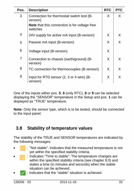
Pos. Description RTC PTC
3 Connection for thermostat switch test (B-version)
Note that this connection is for voltage freeswitches
X X
4 24V supply for active mA input (B-version) X X
5 Passive mA input (B-version) X X
6 Voltage input (B-version) X
7 Connection to chassis (earth/ground) (B-version)
X X
8 TC connection for thermocouples (B-version) X X
9 Input for RTD sensor (2, 3 or 4 wire) (B-version)
X X
One of the inputs either pos. 5, 6 (only RTC), 8 or 9 can be selecteddisplaying the “SENSOR” temperature in the Setup and pos. 1 can bedisplayed as “TRUE” temperature.
Note: Only the sensor type, which is to be tested, should be connectedto the input panel.
3.8 Stability of temperature values
The stability of the TRUE and SENSOR temperatures are indicated bythe following messages:
: ”Not stable": Indicates that the measured temperature is notyet within the specified stability criteria.
: Indicates "Time to stable": The temperature changes arewithin the specified stability criteria (see chapter 8.0) andstates a time (in minutes and seconds) when the stablesituation can be achieved.
: Indicates that the “stable” situation is achieved.
4:32
34 2013-11-18 128206 03
4.0 Operating the Calibrator
4.1 Operating principle
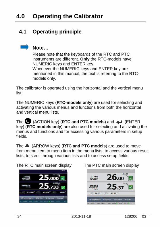
Note…Please note that the keyboards of the RTC and PTCinstruments are different. Only the RTC-models haveNUMERIC keys and ENTER key.Whenever the NUMERIC keys and ENTER key arementioned in this manual, the text is referring to the RTC-models only.
The calibrator is operated using the horizontal and the vertical menulist.
The NUMERIC keys (RTC-models only) are used for selecting andactivating the various menus and functions from both the horizontaland vertical menu lists.
The (ACTION key) (RTC and PTC models) and (ENTERkey) (RTC models only) are also used for selecting and activating themenus and functions and for accessing various parameters in setupfields.
The (ARROW keys) (RTC and PTC models) are used to movefrom menu item to menu item in the menu lists, to access various resultlists, to scroll through various lists and to access setup fields.
The RTC main screen display The PTC main screen display
128206 03 2013-11-18 35
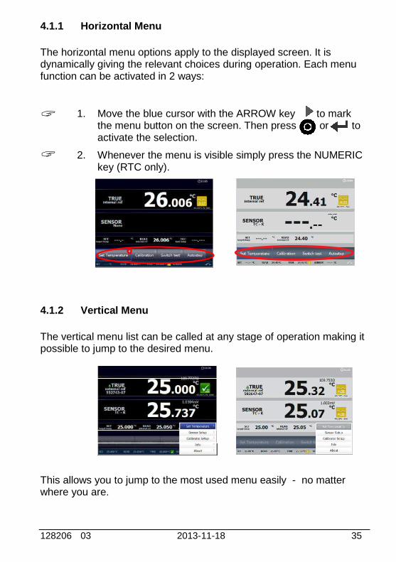
4.1.1 Horizontal Menu
The horizontal menu options apply to the displayed screen. It isdynamically giving the relevant choices during operation. Each menufunction can be activated in 2 ways:
1. Move the blue cursor with the ARROW key to markthe menu button on the screen. Then press or toactivate the selection.
2. Whenever the menu is visible simply press the NUMERICkey (RTC only).
4.1.2 Vertical Menu
The vertical menu list can be called at any stage of operation making itpossible to jump to the desired menu.
This allows you to jump to the most used menu easily - no matterwhere you are.
36 2013-11-18 128206 03
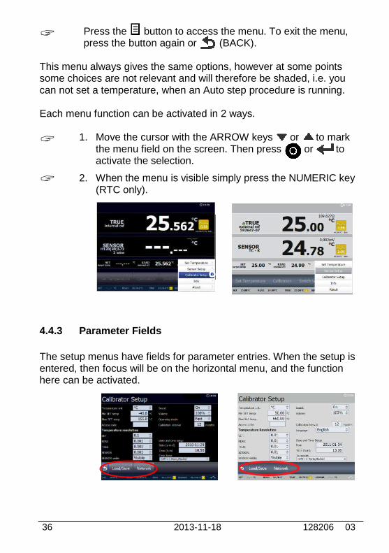
Press the button to access the menu. To exit the menu,press the button again or (BACK).
This menu always gives the same options, however at some pointssome choices are not relevant and will therefore be shaded, i.e. youcan not set a temperature, when an Auto step procedure is running.
Each menu function can be activated in 2 ways.
1. Move the cursor with the ARROW keys or to markthe menu field on the screen. Then press or toactivate the selection.
2. When the menu is visible simply press the NUMERIC key(RTC only).
4.4.3 Parameter Fields
The setup menus have fields for parameter entries. When the setup isentered, then focus will be on the horizontal menu, and the functionhere can be activated.

128206 03 2013-11-18 37
By pressing the ARROW UP key focus will move from thehorizontal menu to the parameter field area.
The parameter field area focus is indicated by The horizontal menu is now shaded The parameter field area has a blue frame (RTC only) The selected parameter field highlighted with a dark
blue color (RTC only) The selected parameter field is highlighted with a dark
grey colour (PTC only)
Use the 4 ARROW keys to move between the parameter fields.
A parameter value is changed by:
Pressing or to open the field for editing. A numeric field can be entered directly without opening
it first – simply enter the number (RTC only).
Press one of the 2 ARROW keys or to movebetween the numeric fields (PTC only).
Enter a numeric field by pressing either or (PTConly).
When the parameter is entered press one of the keys:
This enters the value and leaves the cursor on theparameter field.This enters the value and moves the cursor to the nextparameter field.
°C

38 2013-11-18 128206 03
4.4.4 Working with lists
When it is possible to choose between a number of data sets, the datasets are presented in lists.
As an example access the Calibrator Setup menu from thevertical menu and activate “Load/Save”A list of instruments settings will be displayed.
Press ARROW UP to move the focus from the horizontalmenu to the list.
The selected data set in the list is now highlighted with a darkblue color.

128206 03 2013-11-18 39
Scrolling in the list is done using the ARROW UP key andthe ARROW DOWN key .
When the desired dataset in the list is highlighted press or.
Now the horizontal menu will be in focus again and here youare able to decide what to do with the chosen dataset.
Activate the desired function in the horizontal menu. In thisexample the highlighted Instrument Settings will be loadedfrom the memory into the active setup.
Some lists have no horizontal menus and only one optionavailable.
As an example access the Switch test menu by selecting“Switch test” from the main menu and then activate “Results”.

40 2013-11-18 128206 03
Scroll through the list using the ARROW UP key and theARROW DOWN key and just press or to displaythe result of the highlighted dataset.
4.5 Starting the calibrator
Switch on the calibrator using the power control switch. A start upscreen is displayed and then replaced with the main menu screen:
The functions in the horizontal menu are available using the soft keysor the arrow keys on the keyboard (see description in section 3.4).
4.6 Setting the temperature
Access the Set Temperature function by selecting “SetTemperature “.
°C
°C

128206 03 2013-11-18 41
For RTC models
Use the NUMERIC keys to enter a new value, or or toaccept the value. When pressing the ACTION key or theENTER key the calibrator returns to the main menu screen.
For PTC models
Use the ARROW keys to enter a new value, and toaccept the value and return to the main menu screen. Ifpressing the BACK key the calibrator returns to the mainmenu screen without accepting the new value.
The Set temperature function can also be accessed using thevertical menu (press ). Through this menu a new set pointvalue can be entered at any stage of the operation exceptwhen one of the automatic functions is active.
4.7 Calibration (optional - PTC)
Note…This Calibration function is for B versions only.
This function enables you to perform automatic calibrations of differenttemperature sensors. The calibration procedure is semi-automatic,using parameters and settings, which are defined in workorders. Theseworkorders are created and edited using the "JOFRACAL" PCprogram. Multiple calibrations can be performed using the sameworkorder settings.
Access the Calibration menu by selecting “Calibration” fromthe main menu.
A Workorder List is displayed.
42 2013-11-18 128206 03
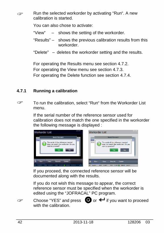
Run the selected workorder by activating “Run“. A newcalibration is started.
You can also chose to activate:
“View” – shows the setting of the workorder.
“Results” – shows the previous calibration results from thisworkorder.
“Delete” – deletes the workorder setting and the results.
For operating the Results menu see section 4.7.2.
For operating the View menu see section 4.7.3.
For operating the Delete function see section 4.7.4.
4.7.1 Running a calibration
To run the calibration, select “Run“ from the Workorder Listmenu.
If the serial number of the reference sensor used forcalibration does not match the one specified in the workorderthe following message is displayed :
If you proceed, the connected reference sensor will bedocumented along with the results.
If you do not wish this message to appear, the correctreference sensor must be specified when the workorder isedited using the “JOFRACAL” PC program.
Choose “YES” and press or if you want to proceedwith the calibration.
128206 03 2013-11-18 43
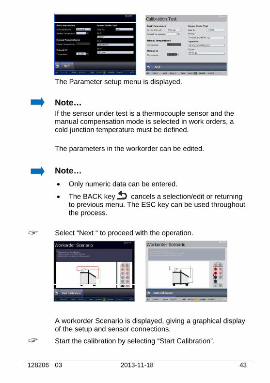
The Parameter setup menu is displayed.
Note…
If the sensor under test is a thermocouple sensor and themanual compensation mode is selected in work orders, acold junction temperature must be defined.
The parameters in the workorder can be edited.
Note…
Only numeric data can be entered.
The BACK key cancels a selection/edit or returningto previous menu. The ESC key can be used throughoutthe process.
Select “Next “ to proceed with the operation.
A workorder Scenario is displayed, giving a graphical displayof the setup and sensor connections.
Start the calibration by selecting “Start Calibration”.
23.50

44 2013-11-18 128206 03
The Calibration Running step 1 of 2 is started and thetemperature is heading towards step 1.
The following screen is displayed :
When the temperature has reached the stable criteria, thecalibration data will be stored and the temperature goestowards the next set temperature.
If the workorder contains manual reading during calibration,you will be asked to enter the Sensor Under Test temperaturebefore that.
The following screen is displayed :
If manual readings are specified these will have to be enteredbefore next step starts.
Note…
The calibration can be stopped at any time by activating“Stop”, but this will erase the calibration results.
°C
128206 03 2013-11-18 45
During calibration several other functions are available:
“Result” - To view the calibration results (no editing ispossible).
“Pause” - To pause the calibration.
“Prev” - Force the calibration to jump a step backwardsto the previous calibration screen regardless ofthe calibration stability.
“Next” - Force the calibration to jump a step forwards tothe next calibration screen regardless of thecalibration stability. This will leave the currentstep without saving calibration results.
“View” - To view the workorder settings.
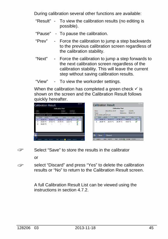
When the calibration has completed a green check isshown on the screen and the Calibration Result followsquickly hereafter.
Select “Save” to store the results in the calibrator
or
select “Discard” and press “Yes” to delete the calibrationresults or “No” to return to the Calibration Result screen.
A full Calibration Result List can be viewed using theinstructions in section 4.7.2.

46 2013-11-18 128206 03
4.7.2 Viewing calibration results
Access the Calibration Result function by selecting
“Results” from the Workorder List menu.
A full Calibration Result List is displayed.
Select a workorder to be displayed showing the calibrationdetails for the specific workorder.
The calibration results can be uploaded with the “JOFRACAL”PC program. This enables you to print out the results on acertificate.
Press to exit the Calibration Result List and return to theWorkorder List menu.
128206 03 2013-11-18 47
4.7.3 Displaying calibration information
Calibration information is defined within the work orders created on thePC using "JOFRACAL".
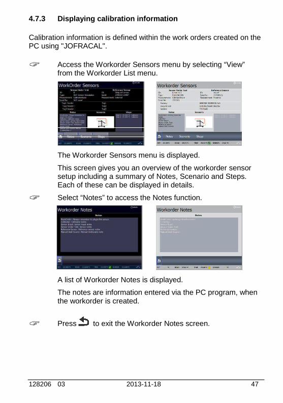
Access the Workorder Sensors menu by selecting “View”from the Workorder List menu.
The Workorder Sensors menu is displayed.
This screen gives you an overview of the workorder sensorsetup including a summary of Notes, Scenario and Steps.Each of these can be displayed in details.
Select “Notes” to access the Notes function.
A list of Workorder Notes is displayed.
The notes are information entered via the PC program, whenthe workorder is created.
Press to exit the Workorder Notes screen.
48 2013-11-18 128206 03
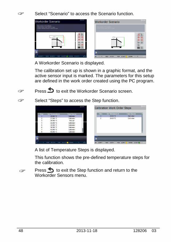
Select “Scenario” to access the Scenario function.
A Workorder Scenario is displayed.
The calibration set up is shown in a graphic format, and theactive sensor input is marked. The parameters for this setupare defined in the work order created using the PC program.
Press to exit the Workorder Scenario screen.
Select “Steps” to access the Step function.
A list of Temperature Steps is displayed.
This function shows the pre-defined temperature steps forthe calibration.
Press to exit the Step function and return to theWorkorder Sensors menu.
128206 03 2013-11-18 49
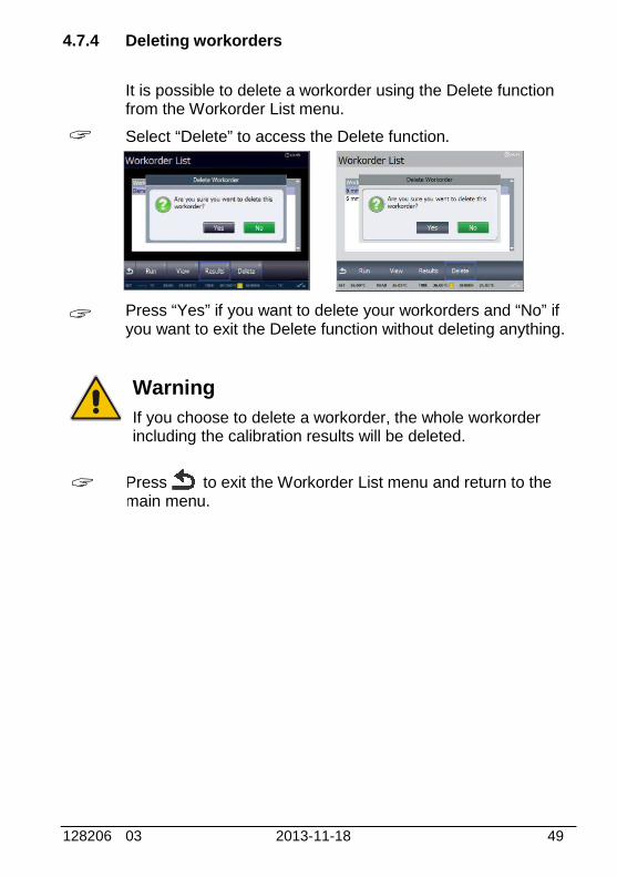
4.7.4 Deleting workorders
It is possible to delete a workorder using the Delete functionfrom the Workorder List menu.
Select “Delete” to access the Delete function.
Press “Yes” if you want to delete your workorders and “No” ifyou want to exit the Delete function without deleting anything.
Warning
If you choose to delete a workorder, the whole workorderincluding the calibration results will be deleted.
Press to exit the Workorder List menu and return to themain menu.

50 2013-11-18 128206 03
4.8 Switch test menu
Note…This Switch test function is for B versions only.
Switch test automatically locates the switch temperatures of athermostat.
Three parameters are required: Start temperature (T1) End temperature (T2) Rate of change in temperature (slope rate).Hysteresis of a thermostat can also be determined here.
4.8.1 Running a switch test
Access the Switch test menu by selecting “Switch test” fromthe main menu.
A Switch test setup menu is displayed.
The small graph illustrates the current T1, T2 and hysteresisselections. Note that T1 can be greater than T2.
128206 03 2013-11-18 51
Access the setup field to edit the parameters:
T1 - first set temperature
T2 - second set temperature
Hysteresis - to determine hysteresis, toggle between"Yes" (a two-way-temperature measurement) and "No"(a one-way-temperature measurement).
Slope rate - The permitted range is 0.1 - 9.9°C/min. /0.2 - 17.8°F/min.
Note…the slope rate should be set so that thethermostat sensor can follow the temperature in thecalibrator's well.
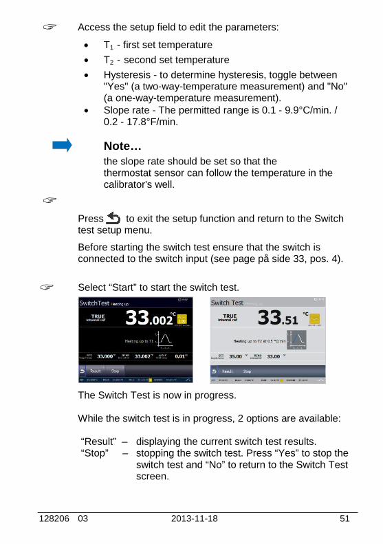
Press to exit the setup function and return to the Switchtest setup menu.
Before starting the switch test ensure that the switch isconnected to the switch input (see page på side 33, pos. 4).
Select “Start” to start the switch test.
The Switch Test is now in progress.
While the switch test is in progress, 2 options are available:
“Result” – displaying the current switch test results.“Stop” – stopping the switch test. Press “Yes” to stop the
switch test and “No” to return to the Switch Testscreen.
°C
52 2013-11-18 128206 03
4.8.2 Showing switch test results
Two types of switch test results are available: Results during a switch test. Results of a finished switch test.
Results during a switch test
Access the Switch Test Result List by selecting “Result” fromthe Switch Test menu.
This shows the results that are currently available. Theseresults change as the test progresses.
Press to return to the switch test.
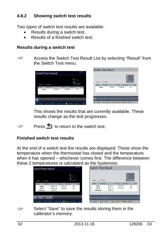
Finished switch test results
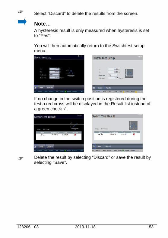
At the end of a switch test the results are displayed. These show thetemperature when the thermostat has closed and the temperaturewhen it has opened – whichever comes first. The difference betweenthese 2 temperatures is calculated as the hysteresis.
Select “Save” to save the results storing them in thecalibrator’s memory.
128206 03 2013-11-18 53
Select “Discard” to delete the results from the screen.
Note…A hysteresis result is only measured when hysteresis is setto “Yes”.
You will then automatically return to the Switchtest setupmenu.
If no change in the switch position is registered during thetest a red cross will be displayed in the Result list instead ofa green check .
Delete the result by selecting “Discard” or save the result byselecting “Save”.
54 2013-11-18 128206 03
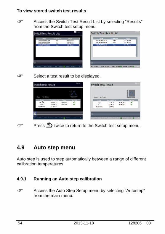
To view stored switch test results
Access the Switch Test Result List by selecting “Results”from the Switch test setup menu.
Select a test result to be displayed.
Press twice to return to the Switch test setup menu.
4.9 Auto step menu
Auto step is used to step automatically between a range of differentcalibration temperatures.
4.9.1 Running an Auto step calibration
Access the Auto Step Setup menu by selecting “Autostep”from the main menu.

128206 03 2013-11-18 55
The Auto Step Setup menu is displayed.
Access the Auto Step Setup to edit the parameters:
No of steps: the number of temperature steps perdirection (T1Tx) can be set using integers from 1 – 20.When a Two-way mode is selected, the same number ofsteps are used for the second direction (TxT1).
Mode: toggle between “One-way” and “Two-way”.
Hold time: defines the time (in minutes) the temperatureis maintained (after it is stable) for each step.
T step values: must be set within the sensors permittedrange.
Press to exit the editor and return to the Auto Step setupmenu.
Access the Sensor setup menu by selecting “Next” from theAuto Step Setup menu.
The Sensor setup menu is displayed. In this menu you havethe opportunity to check and if necessary change thesettings as described in section 4.10 – Sensor Setup menu.
23.00
56 2013-11-18 128206 03
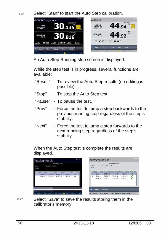
Select “Start” to start the Auto Step calibration.
An Auto Step Running step screen is displayed.
While the step test is in progress, several functions areavailable:
“Result” - To review the Auto Step results (no editing ispossible).
“Stop” - To stop the Auto Step test.
“Pause” - To pause the test.
“Prev” - Force the test to jump a step backwards to theprevious running step regardless of the step’sstability.
“Next” - Force the test to jump a step forwards to thenext running step regardless of the step’sstability.
When the Auto Step test is complete the results aredisplayed.
Select “Save” to save the results storing them in thecalibrator’s memory.
°C

128206 03 2013-11-18 57
Select “Discard” to delete the results from the screen.
The calibrator then returns to the Auto Step Setup menu.
4.9.2 Auto Step test results
At the end of an Auto Step test the results are displayed and stored inthe calibrators memory.
The measured TRUE and SENSOR temperatures for each step aredisplayed.
To view stored Auto step test results
Access the Auto Step Result List by selecting “Results” fromthe Auto Step Setup menu.
The Auto Step Result List is displayed.
Select an auto step result to be displayed.
Press twice to return to the Auto Step Setup menu.
58 2013-11-18 128206 03
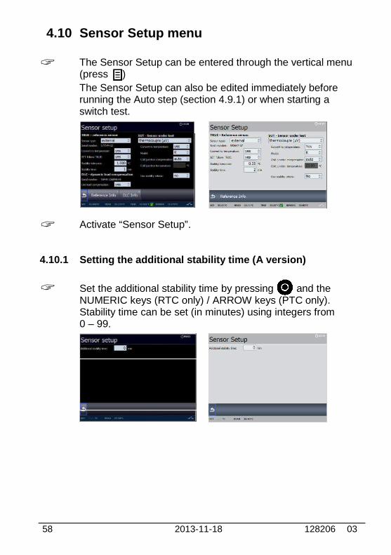
4.10 Sensor Setup menu
The Sensor Setup can be entered through the vertical menu(press )
The Sensor Setup can also be edited immediately beforerunning the Auto step (section 4.9.1) or when starting aswitch test.
Activate “Sensor Setup”.
4.10.1 Setting the additional stability time (A version)
Set the additional stability time by pressing and theNUMERIC keys (RTC only) / ARROW keys (PTC only).Stability time can be set (in minutes) using integers from0 – 99.
23.00
128206 03 2013-11-18 59
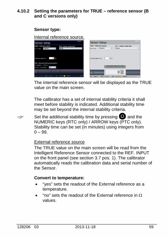
4.10.2 Setting the parameters for TRUE – reference sensor (Band C versions only)
Sensor type:
Internal reference source.
The internal reference sensor will be displayed as the TRUEvalue on the main screen.
The calibrator has a set of internal stability criteria it shallmeet before stability is indicated. Additional stability timemay be set beyond the internal stability criteria.
Set the additional stability time by pressing and theNUMERIC keys (RTC only) / ARROW keys (PTC only).Stability time can be set (in minutes) using integers from0 – 99.
External reference source
The TRUE value on the main screen will be read from theIntelligent Reference Sensor connected to the REF. INPUTon the front panel (see section 3.7 pos. 1). The calibratorautomatically reads the calibration data and serial number ofthe Sensor.
Convert to temperature:
“yes” sets the readout of the External reference as atemperature.
“no” sets the readout of the External reference in values.

60 2013-11-18 128206 03
SET follows TRUE:
This function enables you to reach the TRUE temperaturemeasured by the External reference sensor.
Note…that when “yes” is selected, the calibrator will control thetemperature to the TRUE temperature. This means that itcould take longer time before the calibrator indicatesstability.
The “SET follows TRUE” function is indicated with thesymbol at the TRUE reading in the main display.
Note…SET follows TRUE is only relevant when the Externalreference sensor is displayed in temperature units.
Stability tolerance:
The tolerance should be set low enough to utilize the goodtemperature stability of the calibrator – however a low valuealso gives a longer time to be stable.
Stability time:
Stability time can be set from 1 – 99 minutes.
When the TRUE temperature has reached the specifiedStability tolerance during the specified Stability time, then thestability indicator in the main screen will turn green.
Press to accept the new setting(s) and return to theSensor setup menu or continue to edit the DLC sensorparameters or the Sensor under test parameters.
128206 03 2013-11-18 61
4.10.3 Setting the parameters for DLC– dynamic loadcompensation – (RTC, B and C versions only)
The DLC value on the main screen will be read from theIntelligent Load Sensor as soon as it is connected to theDLC INPUT on the front panel (see section 3.7 pos. 2). Thecalibrator automatically reads the calibration data and serialnumber of the Sensor.
However if the Dynamic Load Compensation shall be active,it must be enabled.
Use load compensation:
The active “DLC” function is indicated with the symbol atthe DLC reading in the main display.
Note…
always use external reference sensor when calibrating withthe DLC-function activated for specified accuracy.
Press to accept the new setting(s) and return to theSensor setup menu or continue to edit the reference sensorparameters or the Sensor under test parameters.
4.10.4 Setting the parameters for SUT– Sensor under test (Bversions only)
Sensor type:
Choose between :
thermocouple sensors (V)
voltage sensors (V) (RTC only)
current sensors (mA)
RTD sensors (resistance temp. detector ())
None (no sensor connected)
Select a sensor.
The selected sensor and its list of parameters are nowdisplayed. The various settings can be edited as described inthe following :
62 2013-11-18 128206 03
Convert to temperature:
(using thermocouple, voltage, current and RTD)
“yes” – the inputs are converted to temperatures.
“no” – no conversion is made.When “no” has been selected the type of model is theonly other parameter which can be altered.
Model:
(using thermocouple and RTD)
Toggle between the models; K, L, N, R, S, T, U, B, E and J(thermocouple) or *P10(90)385, *P50(90)385, P100(90)385,*P200(90)385,*P500(90)385, P1000(90)385, *P50(90)391,P100(90)391, P100(90)392, *Pt-100 MILL, *YSI-400,H120(90)672, *M100(90)428… and *M50(90)428 (RTD).
* Optional – PTC
Cold junction compensation:
(using thermocouple)
“auto” – when the automatic mode is selected, thecalibrator measures the temperature in the T/Cconnector and uses this for the cold junctioncompensation of the thermocouple.
“manual” – to define a manual temperature for coldjunction compensation. Can be used when an externalcold junction temperature can be established.
Cold junction temperature:
(using thermocouple)
When “manual” Cold junction compensation has beenselected the temperature for cold junction can be set usingthe NUMERIC keys (RTC only) / ARROW keys (PTC only).
Voltage(V) and temperature(T) span (RTC only):
(using voltage)
The minimum and the maximum of the voltage and thecorresponding temperature span can be set here.
128206 03 2013-11-18 63
Use the NUMERIC keys to set the value of the voltageand/or the temperature.
Current(C) and temperature(T) span:
(using current)
The minimum and the maximum of the current and thecorresponding temperature span can be set here.
Use the NUMERIC keys (RTC only) / ARROW keys (PTConly) to set the value of the current and/or the temperature.
Number of wires:(using RTD)
The number of wires used for the sensor under test can beselected here.
Choose between 2, 3 or 4 wires.
Use stability criteria:
(using thermocouple, voltage (RTC only), current and RTD)
Beside the stability check on the Reference sensor, it is alsopossible to ensure that the Sensor Under Test (SENSOR) isstable before the temperature is indicated as stable.
“yes” – Stability will be checked on both Referencesensor (TRUE) temperature and Sensor Under Test(SENSOR) temperature.
“no” – Stability will be checked on Reference sensor(TRUE) temperature only.
Stability tolerance:
(using thermocouple, voltage (RTC only), current and RTD)
Enter the Stability tolerance (temperature) by pressing theNUMERIC keys (RTC only) / ARROW keys (PTC only).
The expected performance of the Sensor Under Test shouldbe considered before setting the tolerance.
64 2013-11-18 128206 03
Stability time:
(using thermocouple, voltage (RTC only), current and RTD)
Set the Stability time by pressing the NUMERIC keys (RTConly) / ARROW keys (PTC only). Stability time can be setfrom 1 – 99 minutes.
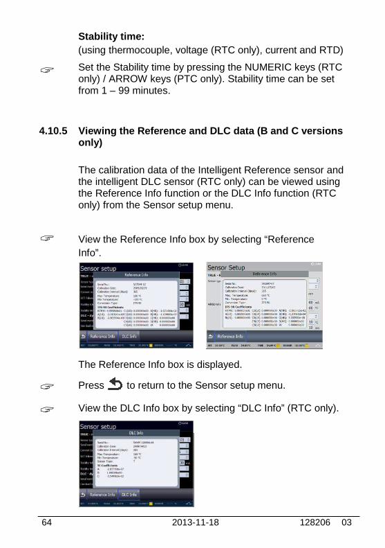
4.10.5 Viewing the Reference and DLC data (B and C versionsonly)
The calibration data of the Intelligent Reference sensor andthe intelligent DLC sensor (RTC only) can be viewed usingthe Reference Info function or the DLC Info function (RTConly) from the Sensor setup menu.
View the Reference Info box by selecting “Reference
Info”.
The Reference Info box is displayed.
Press to return to the Sensor setup menu.
View the DLC Info box by selecting “DLC Info” (RTC only).
128206 03 2013-11-18 65
The DLC Info box is displayed.
Press to return to the Sensor setup menu.
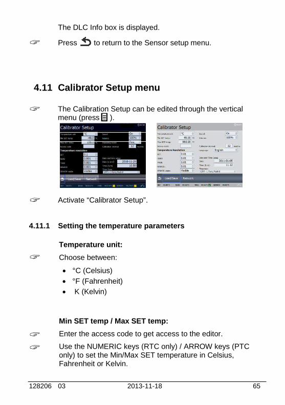
4.11 Calibrator Setup menu
The Calibration Setup can be edited through the verticalmenu (press ).
Activate “Calibrator Setup”.
4.11.1 Setting the temperature parameters
Temperature unit:
Choose between:
°C (Celsius)
°F (Fahrenheit)
K (Kelvin)
Min SET temp / Max SET temp:
Enter the access code to get access to the editor.
Use the NUMERIC keys (RTC only) / ARROW keys (PTConly) to set the Min/Max SET temperature in Celsius,Fahrenheit or Kelvin.
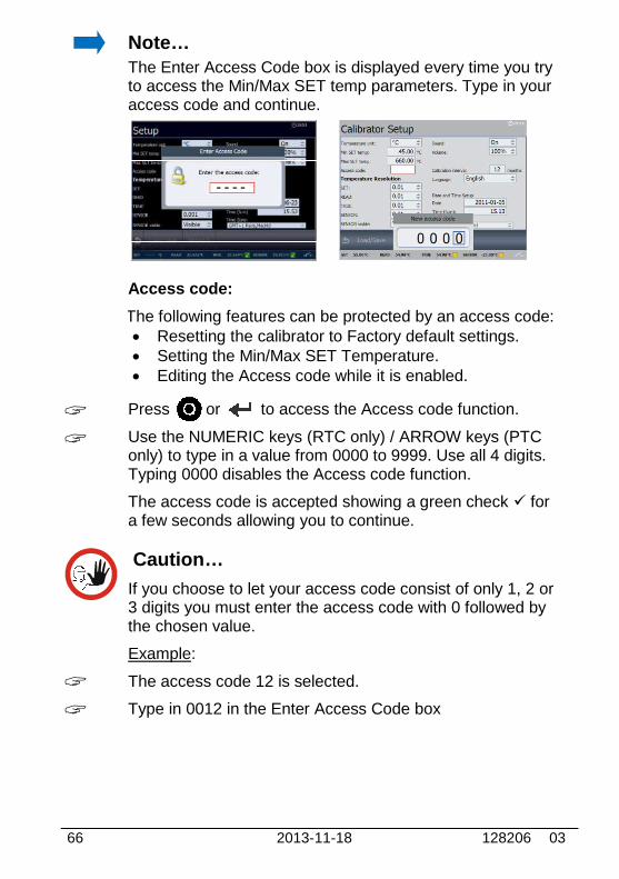
66 2013-11-18 128206 03
Note…The Enter Access Code box is displayed every time you tryto access the Min/Max SET temp parameters. Type in youraccess code and continue.
Access code:
The following features can be protected by an access code: Resetting the calibrator to Factory default settings. Setting the Min/Max SET Temperature. Editing the Access code while it is enabled.
Press or to access the Access code function.
Use the NUMERIC keys (RTC only) / ARROW keys (PTConly) to type in a value from 0000 to 9999. Use all 4 digits.Typing 0000 disables the Access code function.
The access code is accepted showing a green check fora few seconds allowing you to continue.
Caution…
If you choose to let your access code consist of only 1, 2 or3 digits you must enter the access code with 0 followed bythe chosen value.
Example:
The access code 12 is selected.
Type in 0012 in the Enter Access Code box
128206 03 2013-11-18 67
Note…
The access code can be deleted allowing you to change theMin/Max SET temperature without having to enter theaccess code.
Press or to access the Access code function.
Type in your access code.
No new value is entered.
Accept the new setting (empty box).
It is now possible to enter the editor without using theaccess code.
4.11.2 Setting the temperature resolution
Choose between :
SET READ TRUE SENSOR
Choose between the resolutions:
0.001 (RTC only) 0.01 0.1 1
SENSOR visible:
Choose between :
Visible Hidden
If the Hidden option is chosen the Sensor Under Testreading will not be displayed on the main screen.
68 2013-11-18 128206 03
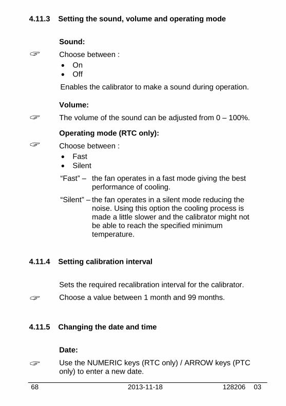
4.11.3 Setting the sound, volume and operating mode
Sound:
Choose between :
On Off
Enables the calibrator to make a sound during operation.
Volume:
The volume of the sound can be adjusted from 0 – 100%.
Operating mode (RTC only):
Choose between :
Fast Silent
“Fast” – the fan operates in a fast mode giving the bestperformance of cooling.
“Silent” – the fan operates in a silent mode reducing thenoise. Using this option the cooling process ismade a little slower and the calibrator might notbe able to reach the specified minimumtemperature.
4.11.4 Setting calibration interval
Sets the required recalibration interval for the calibrator.
Choose a value between 1 month and 99 months.
4.11.5 Changing the date and time
Date:
Use the NUMERIC keys (RTC only) / ARROW keys (PTConly) to enter a new date.
128206 03 2013-11-18 69
The date can only be entered using the format yyyy-mm-dd.When entering the date with different format, the text willdisappear when you try to accept the setting.
Time:
The calibrator is set up with a default time (present time).
Use the NUMERIC keys (RTC only) / ARROW keys (PTConly) to enter a new time using the format hh.mm.
Time Zone:
The relevant time zone is selected from a list of variouszones.
4.11.6 Choosing a language (optional)
The calibrator is set up with a default language - English.
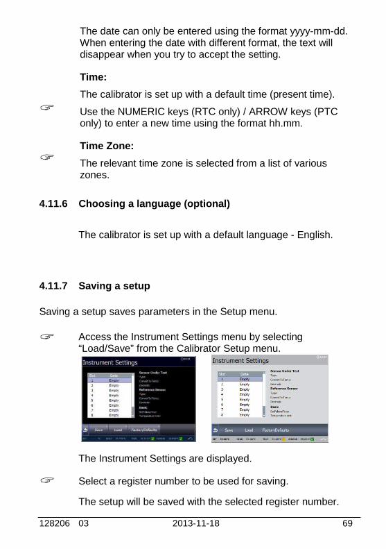
4.11.7 Saving a setup
Saving a setup saves parameters in the Setup menu.
Access the Instrument Settings menu by selecting“Load/Save” from the Calibrator Setup menu.
The Instrument Settings are displayed.
Select a register number to be used for saving.
The setup will be saved with the selected register number.
70 2013-11-18 128206 03
Note…
In the Calibrator Setup the following parameters will not besaved:
Min SET temp
Max SET temp
SENSOR visible
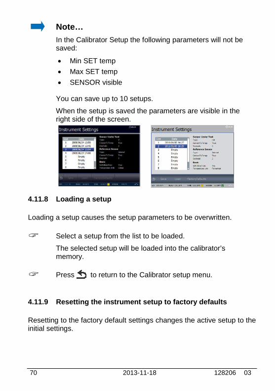
You can save up to 10 setups.
When the setup is saved the parameters are visible in theright side of the screen.
4.11.8 Loading a setup
Loading a setup causes the setup parameters to be overwritten.
Select a setup from the list to be loaded.
The selected setup will be loaded into the calibrator’smemory.
Press to return to the Calibrator setup menu.
4.11.9 Resetting the instrument setup to factory defaults
Resetting to the factory default settings changes the active setup to theinitial settings.
128206 03 2013-11-18 71
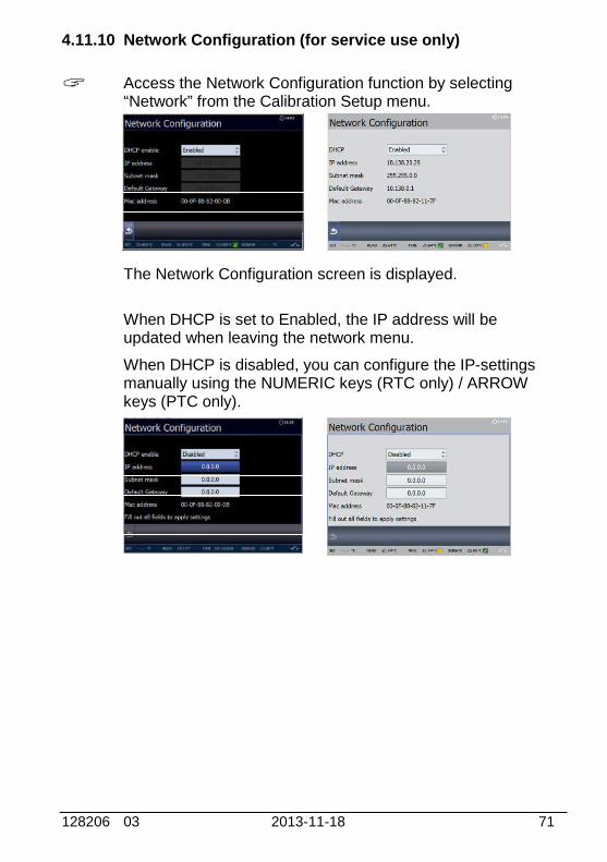
4.11.10 Network Configuration (for service use only)
Access the Network Configuration function by selecting“Network” from the Calibration Setup menu.
The Network Configuration screen is displayed.
When DHCP is set to Enabled, the IP address will beupdated when leaving the network menu.
When DHCP is disabled, you can configure the IP-settingsmanually using the NUMERIC keys (RTC only) / ARROWkeys (PTC only).

72 2013-11-18 128206 03
4.12 Selecting the stirrer speed (RTC-158/250only)
Use the NUMERIC keys to enter a value, or or toaccept the value. When pressing the ACTION key or theENTER key the calibrator returns to the main menu screen.
Select a speed setting between 0 and 100.The normal setting is between 30 and 40.
When using the RTC-158/250 A/B/C with a dry block kit thestirrer speed must be set to 0.
The DLC will be disabled when the stirrer is started
The Sensor Setup can be entered through the vertical menu(press )
Use the ARROW keys to select “Stirrer Speed”.
128206 03 2013-11-18 73
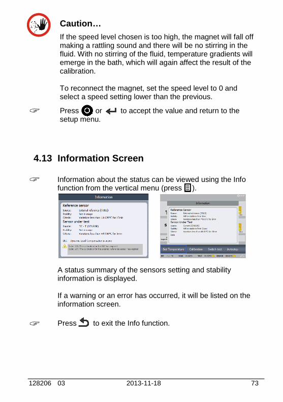
Caution…
If the speed level chosen is too high, the magnet will fall offmaking a rattling sound and there will be no stirring in thefluid. With no stirring of the fluid, temperature gradients willemerge in the bath, which will again affect the result of thecalibration.
To reconnect the magnet, set the speed level to 0 andselect a speed setting lower than the previous.
Press or to accept the value and return to thesetup menu.
4.13 Information Screen
Information about the status can be viewed using the Infofunction from the vertical menu (press ).
A status summary of the sensors setting and stabilityinformation is displayed.
If a warning or an error has occurred, it will be listed on theinformation screen.
Press to exit the Info function.

74 2013-11-18 128206 03
4.14 About the calibrator
Information about the calibrator can be viewed using theAbout function from the vertical menu (press ).
Press to exit the About function.

128206 03 2013-11-18 75
5.0 Setting the mains voltage andreplacing the main fuses
Warning The calibrator must be switched off before any attempt
to service the instrument is made. There are no userserviceable parts inside the calibrator.
The fuse box must not be removed from the powercontrol switch until the mains cable has beendisconnected.
The two main fuses must have the specified current andvoltage rating and be of the specified type. The use ofmakeshift fuses and the short-circuiting of fuse holdersare prohibited and may cause a hazard.
This image shows the RTC-model
Fig. 6
Locate the main fuses in the fuse box in the power controlswitch and check the voltage of the power control switch(on/off switch (230V/115V)). If the voltage of the powercontrol switch differs from the line voltage, you must adjustthe voltage of the power control switch.
2
43
1
4
76 2013-11-18 128206 03
Open the lid of the fuse box using a screwdriver.
Remove the fuse box.
Replace the fuses. The new fuses must be identical andshould correspond to the line voltage.
RTC-156/157/158/159, PTC-125/155: 115V 8AT = 127211230V, 4AT = 127210
RTC-250/700, PTC-350/660: 115V, 10AF = 60B302230V, 5AF = 127573
Slide the fuse box into place with the correct voltage turningupwards.
If the fuses blow immediately after you have replaced them,the calibrator should be returned to the manufacturer forservice.
128206 03 2013-11-18
6.0 After use
6.1 Storing and transporting the calibrator
Caution…
The following guidelines should always be observed whenstoring and transporting the calibrators. This will ensure thatthe instruments and the sensors remain in good workingorder.
Warning (all heating dry-block models)
Never leave hot insertion tubes that have been removedfrom the calibrator unsupervised – they may constitute afire hazard or personal injury.
If you intend to store the calibrator in the optionalaluminium carrying case after use, you mustthe instrument has cooled to a temperature100°C/212°F before placing it in the carrying case.
Never place a hot insertion tube in the optional carryingcase.
Caution…(all dry-block models)
The insertion tube must always be removed from thecalibrator after use.The humidity in the air may cause oxidation on the insertiontube inside the instrument. There is a risk that the insertiontube may get stuck if this is allowed to happen.
Below 0°C/32°F(applies only to the RTC-156/157/158/159, PTCA/B/C models)
If the calibrator has reached a temperature below0°C/32°F, ice crystals may form on the insertion tubeand on the well. This, in turn, may cause the materialsurfaces to oxidize.To prevent this from happening, the insertion tube and
77
Storing and transporting the calibrators
The following guidelines should always be observed when. This will ensure that
remain in good working
leave hot insertion tubes that have been removedthey may constitute a
If you intend to store the calibrator in the optionalmust ensure that
the instrument has cooled to a temperature belowbefore placing it in the carrying case.
place a hot insertion tube in the optional carrying
be removed from the
The humidity in the air may cause oxidation on the insertiontube inside the instrument. There is a risk that the insertion
stuck if this is allowed to happen.
, PTC-125/155
If the calibrator has reached a temperature below0°C/32°F, ice crystals may form on the insertion tubeand on the well. This, in turn, may cause the material
To prevent this from happening, the insertion tube and
78 2013-11-18 128206 03
the well must be dried. This is done by heating up thecalibrator to min. 100°C/212°F until all water left hasevaporated.Remove the insulation plug while heating up.
It is very important that humidity in the well and insertiontube is removed to prevent corrosion and frostexpansion damages.
Do not touch the well or insertion tube when these aredeep frozen – they might create frostbite.
6.2 Handling the dry-block calibrator
The following guidelines must be observed before the insertion tubeis removed and the instrument switched off:
Caution – Hot surfaceDo not remove the insertion tube from the calibrator beforethe insertion tube has cooled down to less than 50°C/122°F
1. If the calibrator has been heated to temperaturesthan above 50°C/122°F, you must wait until the instrument
reaches a temperature below 50°C/122°F beforeyou switch it off.
2. If the calibrator has reached a temperature below 0°C/32°F, itshould be heated to a temperature of 100°C/212°F (applies only tothe RTC-156/157/158/159, PTC-125/155 A/B/C models).
3. Remove the insulation plug while heating up.
4. Switch off the calibrator using the power control switch.
Note that the calibration procedure may be interrupted at any timeusing the power control switch. Turning off the calibrator during thecalibration process will not damage either the instrument or thesensor.
5. Remove the insertion tube from the calibrator using the toolsupplied with the instrument.
6. Optional: Store the calibrator in its protective, aluminium carryingcase.

128206 03 2013-11-18 79
6.3 Handling the liquid-bath calibrator (RTC-158/250 only)
WarningAlways remove the liquid from the calibrator beforetransportation.
It is not recommendable to leave the fluid in the well for long-termstorage. The best way to store the fluid is in its original airtightcontainer.It is recommended to remove the oil from the well before transportationof the calibrator. It is, however, possible to move the liquid bathcalibrator by hand, when it is filled with fluids.The transportation lid is used to reduce the risk of spilling.
As the lid is not completely fluid tight it is advisable to emptying the wellcompletely before any transportation is attempted.
Caution – Hot surface
Do not handle hot fluid.
Do not attempt to remove hot fluid with the liquid drainagetube, as it might melt.
Do not leave any fluid (silicone oil) in the spill tray.
Do not touch the items removed from the well – they maybe very hot and cause burns.
Never leave hot items, which have been removed from thewell, unsupervised – they may constitute a fire hazard orpersonal injury.
The following guidelines must be observed before emptying the well :
1. Switch off the calibrator using the power control switch.
2. Before handling the fluid, it must be cooled down to a temperatureclose to ambient.
3. Remove the sensor basket and clean it with disposable papertowels.

80 2013-11-18 128206 03
4. Remove the stirring magnet using the stirring magnet removersupplied and clean it with disposable paper towels.
5. Empty the well using the liquid drainage tube supplied. Tilting thecalibrator is not recommendable, as it increases the risk ofsplashing oil all over the test area.
Caution…Avoid getting silicone oil on the clothes. It is impossible towash off.
6. Any remaining oil in the well is cleaned up using disposable papertowels. It is recommendable to use the optional cleaning oil whencleaning the well.
Warning REMEMBER, wear goggles when using the cleaning oil.
Do not inhale vapours. Proper ventilation must be used.
Product information on cleaning oil must be carefullyinvestigated before use.
Information in this document is subject to change without notice. ©2012, by AMETEK, Inc., www.ametek.com. All rights reserved.
AMETEK Calibration Instrumentsis one of the world’s leading manufacturers
and developers of calibration instruments for temperature, pressure and process signals as well
as for temperature sensors both from a commercial and a technological point of view.
JOFRA Temperature InstrumentsPortable precision thermometers. Dry-block and
liquid bath calibrators: 5 series, with more than 25 models and temperature ranges from -90° to
1205°C / -130° to 2200°F. All featuring speed, portability, accuracy and advanced documenting
functions with JOFRACAL calibration software.
JOFRA Pressure InstrumentsConvenient electronic systems ranging from -25
mbar to 1000 bar (0.4 to 15,000 psi) - multiple choices of pressure ranges, pumps and accuracies,
fully temperature-compensated for problem-free and accurate field use.
JOFRA Signal InstrumentsProcess signal measurement and simulation for easy control loop calibration and measurement
tasks - from handheld field instruments to laboratory reference level bench top instruments.
JOFRA / JF Marine InstrumentsA complete range of calibration equipment for
temperature, pressure and signal, approved for marine use.
FP Temperature SensorsA complete range of temperature sensors for
industrial and marine use.
M&G Pressure TestersPneumatic floating-ball or hydraulic piston dead
weight testers with accuracies to 0.015% of reading.
M&G PumpsPressure generators from small pneumatic “bicycle”
style pumps to hydraulic pumps generating up to 1,000 bar (15,000 psi).
www.jofra.com
UKAMETEK Calibration InstrumentsTel +44 (0)1243 833 [email protected]
FranceAMETEK S.A.S.Tel +33 (0)1 30 68 89 [email protected]
GermanyAMETEK GmbHTel +49 (0)2159 9136 [email protected]
DenmarkAMETEK DenmarkTel +45 4816 [email protected]
USAAMETEK Mansfield & GreenTel +1 (800) 527 [email protected]
IndiaAMETEK Instruments India Pvt Ltd.Tel +91 22 2836 [email protected]
Singapore AMETEK Singapore Pte LtdTel +65 6484 [email protected]
ChinaAMETEK Inc. - ShanghaiTel +86 21 5868 5111
AMETEK Inc. - BeijingTel +86 10 8526 2111
AMETEK Inc. - GuangzhouTel +86 20 8363 [email protected]


