– Automotive grade A• Operating temperature ranges2
– From –40°C to +95°C IT– From –40°C to +105°C AT
Notes: 1. The JEDEC specification is available athttp://www.jedec.org/standards-documents/docs/jesd220d.pdf.
2. Operating temperature (TOPER) is the casesurface temperature on the center/top ofthe package.
Micron Confidential and Proprietary Advance‡
128GB, 256GB: Automotive UFS MemoryFeatures
CCM005-816717818-10550auto_153ball_ufs_v31_120s_tlc.pdf - Rev. B 05/2020 EN 1 Micron Technology, Inc. reserves the right to change products or specifications without notice.
‡Products and specifications discussed herein are for evaluation and reference purposes only and are subject to change byMicron without notice. Products are only warranted by Micron to meet Micron's production data sheet specifications.
Notes: 1. All the above MPNs can be ordered in the shipping form of tray and tape and reel.2. Products and specifications discussed herein are for evaluation and reference purposes only and are subject
to change by Micron without notice. Products are only warranted by Micron to meet Micron’s productiondata sheet specifications.
Device Marking
Due to the size of the package, the Micron-standard part number is not printed on the top of the device. Instead,an abbreviated device mark consisting of a 5-digit alphanumeric code is used. The abbreviated device marks arecross-referenced to the Micron part numbers at the FBGA Part Marking Decoder site: www.micron.com/decoder.
Micron Confidential and Proprietary Advance
128GB, 256GB: Automotive UFS MemoryFeatures
CCM005-816717818-10550auto_153ball_ufs_v31_120s_tlc.pdf - Rev. B 05/2020 EN 2 Micron Technology, Inc. reserves the right to change products or specifications without notice.
ContentsImportant Notes and Warnings ......................................................................................................................... 6General Description ......................................................................................................................................... 7UFS Performance and Current Consumption .................................................................................................... 8Signal Descriptions ........................................................................................................................................... 9Signal Assignments ......................................................................................................................................... 10Package Dimensions ....................................................................................................................................... 11Architecture ................................................................................................................................................... 12UFS M-PHY Attributes .................................................................................................................................... 13UPIU Transaction Codes ................................................................................................................................. 16UFS Descriptors ............................................................................................................................................. 17UFS Flags, Attributes, and Commands ............................................................................................................. 34UFS Supported Pages ..................................................................................................................................... 42UFS Vital Product Data Parameters ................................................................................................................. 48Electrical Specifications .................................................................................................................................. 57Revision History ............................................................................................................................................. 58
Rev. B – 05/2020 ......................................................................................................................................... 58Rev. A – 03/2020 .......................................................................................................................................... 58
Micron Confidential and Proprietary Advance
128GB, 256GB: Automotive UFS MemoryFeatures
CCM005-816717818-10550auto_153ball_ufs_v31_120s_tlc.pdf - Rev. B 05/2020 EN 3 Micron Technology, Inc. reserves the right to change products or specifications without notice.
CCM005-816717818-10550auto_153ball_ufs_v31_120s_tlc.pdf - Rev. B 05/2020 EN 4 Micron Technology, Inc. reserves the right to change products or specifications without notice.
CCM005-816717818-10550auto_153ball_ufs_v31_120s_tlc.pdf - Rev. B 05/2020 EN 5 Micron Technology, Inc. reserves the right to change products or specifications without notice.
Important Notes and WarningsMicron Technology, Inc. ("Micron") reserves the right to make changes to information published in this document,including without limitation specifications and product descriptions. This document supersedes and replaces allinformation supplied prior to the publication hereof. You may not rely on any information set forth in this docu-ment if you obtain the product described herein from any unauthorized distributor or other source not authorizedby Micron.
Automotive Applications. Products are not designed or intended for use in automotive applications unless specifi-cally designated by Micron as automotive-grade by their respective data sheets. Distributor and customer/distrib-utor shall assume the sole risk and liability for and shall indemnify and hold Micron harmless against all claims,costs, damages, and expenses and reasonable attorneys' fees arising out of, directly or indirectly, any claim ofproduct liability, personal injury, death, or property damage resulting directly or indirectly from any use of non-automotive-grade products in automotive applications. Customer/distributor shall ensure that the terms and con-ditions of sale between customer/distributor and any customer of distributor/customer (1) state that Micronproducts are not designed or intended for use in automotive applications unless specifically designated by Micronas automotive-grade by their respective data sheets and (2) require such customer of distributor/customer to in-demnify and hold Micron harmless against all claims, costs, damages, and expenses and reasonable attorneys'fees arising out of, directly or indirectly, any claim of product liability, personal injury, death, or property damageresulting from any use of non-automotive-grade products in automotive applications.
Critical Applications. Products are not authorized for use in applications in which failure of the Micron compo-nent could result, directly or indirectly in death, personal injury, or severe property or environmental damage("Critical Applications"). Customer must protect against death, personal injury, and severe property and environ-mental damage by incorporating safety design measures into customer's applications to ensure that failure of theMicron component will not result in such harms. Should customer or distributor purchase, use, or sell any Microncomponent for any critical application, customer and distributor shall indemnify and hold harmless Micron andits subsidiaries, subcontractors, and affiliates and the directors, officers, and employees of each against all claims,costs, damages, and expenses and reasonable attorneys' fees arising out of, directly or indirectly, any claim ofproduct liability, personal injury, or death arising in any way out of such critical application, whether or not Mi-cron or its subsidiaries, subcontractors, or affiliates were negligent in the design, manufacture, or warning of theMicron product.
Customer Responsibility. Customers are responsible for the design, manufacture, and operation of their systems,applications, and products using Micron products. ALL SEMICONDUCTOR PRODUCTS HAVE INHERENT FAIL-URE RATES AND LIMITED USEFUL LIVES. IT IS THE CUSTOMER'S SOLE RESPONSIBILITY TO DETERMINEWHETHER THE MICRON PRODUCT IS SUITABLE AND FIT FOR THE CUSTOMER'S SYSTEM, APPLICATION, ORPRODUCT. Customers must ensure that adequate design, manufacturing, and operating safeguards are includedin customer's applications and products to eliminate the risk that personal injury, death, or severe property or en-vironmental damages will result from failure of any semiconductor component.
Limited Warranty. In no event shall Micron be liable for any indirect, incidental, punitive, special or consequentialdamages (including without limitation lost profits, lost savings, business interruption, costs related to the removalor replacement of any products or rework charges) whether or not such damages are based on tort, warranty,breach of contract or other legal theory, unless explicitly stated in a written agreement executed by Micron's dulyauthorized representative.
Micron Confidential and Proprietary Advance
128GB, 256GB: Automotive UFS MemoryImportant Notes and Warnings
CCM005-816717818-10550auto_153ball_ufs_v31_120s_tlc.pdf - Rev. B 05/2020 EN 6 Micron Technology, Inc. reserves the right to change products or specifications without notice.
General DescriptionMicron universal flash storage (UFS) is a communication and mass data storage devicethat includes an M-PHY interface, one or more NAND Flash components, and a con-troller on an advanced 6-signal bus, which is compliant with the UFS system specifica-tion. Its cost per bit, small package sizes, and high reliability make it an ideal choice forautomotive applications, including information and entertainment, navigation tools,advanced driving assistance systems, and a variety of other industrial and portableproducts.
The nonvolatile UFS draws no power to maintain stored data, delivers high perform-ance across a wide range of operating temperatures, and resists shock and vibration dis-ruption.
CCM005-816717818-10550auto_153ball_ufs_v31_120s_tlc.pdf - Rev. B 05/2020 EN 7 Micron Technology, Inc. reserves the right to change products or specifications without notice.
Note: 1. Two lanes, high-speed mode gear 4; sequential access of 512KB chunk; random access of4KB chunk; command queue depth = 32, burst performance
Additional performance data, such as sustained and system performance on a specificapplication board, will be provided in a separate document upon customer request.
Notes: 1. Two lanes, high-speed mode gear 4; VCC = 2.5V; VCCQ = 1.2V; TOPER = 25°C, measurementsdone as average RMS current consumption
2. Two lanes, high-speed mode gear 4; VCC = 2.5V; VCCQ = 1.2V; TOPER = 85°C, measurementsbandwidth of 250 KHz
Table 4: Low-Power Mode
Condition1
Typical Values (ICC/ICCQ) Maximum Values (ICC/ICCQ)
Unit128GB 256GB 128GB 256GB
Sleep TBD TBD TBD TBD µA
Idle TBD TBD TBD TBD µA
Note: 1. Two lanes, low-speed mode PWM gear 4, M-PHY in Hibernate; VCC = 2.5V; VCCQ = 1.2V;TOPER = 25°C
Micron Confidential and Proprietary Advance
128GB, 256GB: Automotive UFS MemoryUFS Performance and Current Consumption
CCM005-816717818-10550auto_153ball_ufs_v31_120s_tlc.pdf - Rev. B 05/2020 EN 8 Micron Technology, Inc. reserves the right to change products or specifications without notice.
CCM005-816717818-10550auto_153ball_ufs_v31_120s_tlc.pdf - Rev. B 05/2020 EN 9 Micron Technology, Inc. reserves the right to change products or specifications without notice.
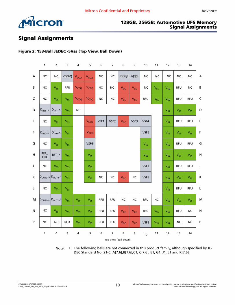
Note: 1. The following balls are not connected in this product family, although specified by JE-DEC Standard No. 21-C: A[7:6],B[7:6],C1, C[7:6], E1, G1, J1, L1 and K[7:6]
CCM005-816717818-10550auto_153ball_ufs_v31_120s_tlc.pdf - Rev. B 05/2020 EN 10 Micron Technology, Inc. reserves the right to change products or specifications without notice.
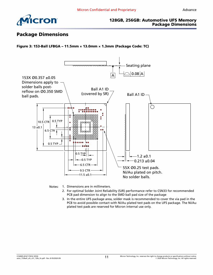
55X Ø0.25 test pads.Ni/Au plated on pitch.No solder balls.
0.5 TYP
0.5 TYP
0.5 TYP
0.5 TYP
6.5 CTR
9.5 CTR11.5 ±0.1
13 ±0.1
10.5 CTR
6.5 CTR
Notes: 1. Dimensions are in millimeters.2. For optimal Solder Joint Reliability (SJR) performance refer to CSN33 for recommended
PCB pad dimension to align to the SMD ball pad size of the package3. In the entire UFS package area, solder mask is recommended to cover the via pad in the
PCB to avoid possible contact with Ni/Au plated test pads on the UFS package. The Ni/Auplated test pads are reserved for Micron internal use only.
CCM005-816717818-10550auto_153ball_ufs_v31_120s_tlc.pdf - Rev. B 05/2020 EN 11 Micron Technology, Inc. reserves the right to change products or specifications without notice.
CCM005-816717818-10550auto_153ball_ufs_v31_120s_tlc.pdf - Rev. B 05/2020 EN 12 Micron Technology, Inc. reserves the right to change products or specifications without notice.
CCM005-816717818-10550auto_153ball_ufs_v31_120s_tlc.pdf - Rev. B 05/2020 EN 13 Micron Technology, Inc. reserves the right to change products or specifications without notice.
CCM005-816717818-10550auto_153ball_ufs_v31_120s_tlc.pdf - Rev. B 05/2020 EN 14 Micron Technology, Inc. reserves the right to change products or specifications without notice.
CCM005-816717818-10550auto_153ball_ufs_v31_120s_tlc.pdf - Rev. B 05/2020 EN 15 Micron Technology, Inc. reserves the right to change products or specifications without notice.
CCM005-816717818-10550auto_153ball_ufs_v31_120s_tlc.pdf - Rev. B 05/2020 EN 16 Micron Technology, Inc. reserves the right to change products or specifications without notice.
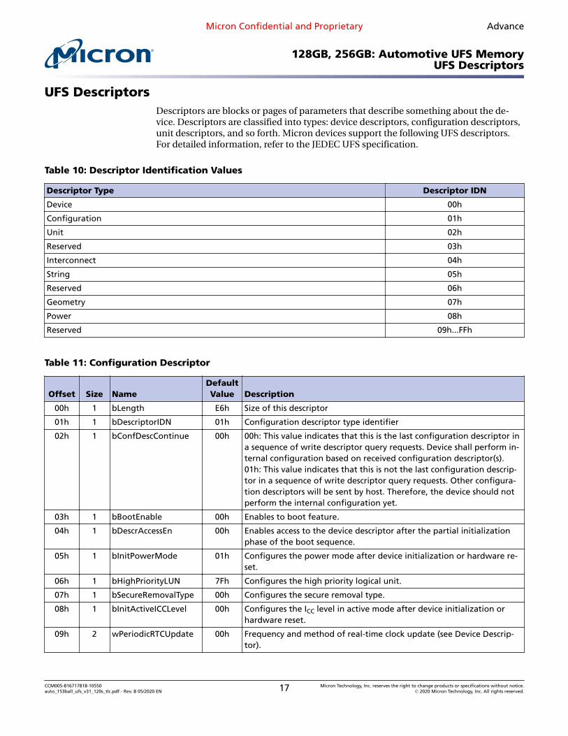
UFS DescriptorsDescriptors are blocks or pages of parameters that describe something about the de-vice. Descriptors are classified into types: device descriptors, configuration descriptors,unit descriptors, and so forth. Micron devices support the following UFS descriptors.For detailed information, refer to the JEDEC UFS specification.
Table 10: Descriptor Identification Values
Descriptor Type Descriptor IDN
Device 00h
Configuration 01h
Unit 02h
Reserved 03h
Interconnect 04h
String 05h
Reserved 06h
Geometry 07h
Power 08h
Reserved 09h...FFh
Table 11: Configuration Descriptor
Offset Size NameDefaultValue Description
00h 1 bLength E6h Size of this descriptor
01h 1 bDescriptorIDN 01h Configuration descriptor type identifier
02h 1 bConfDescContinue 00h 00h: This value indicates that this is the last configuration descriptor ina sequence of write descriptor query requests. Device shall perform in-ternal configuration based on received configuration descriptor(s).01h: This value indicates that this is not the last configuration descrip-tor in a sequence of write descriptor query requests. Other configura-tion descriptors will be sent by host. Therefore, the device should notperform the internal configuration yet.
03h 1 bBootEnable 00h Enables to boot feature.
04h 1 bDescrAccessEn 00h Enables access to the device descriptor after the partial initializationphase of the boot sequence.
05h 1 bInitPowerMode 01h Configures the power mode after device initialization or hardware re-set.
06h 1 bHighPriorityLUN 7Fh Configures the high priority logical unit.
07h 1 bSecureRemovalType 00h Configures the secure removal type.
08h 1 bInitActiveICCLevel 00h Configures the ICC level in active mode after device initialization orhardware reset.
09h 2 wPeriodicRTCUpdate 00h Frequency and method of real-time clock update (see Device Descrip-tor).
CCM005-816717818-10550auto_153ball_ufs_v31_120s_tlc.pdf - Rev. B 05/2020 EN 17 Micron Technology, Inc. reserves the right to change products or specifications without notice.
CCM005-816717818-10550auto_153ball_ufs_v31_120s_tlc.pdf - Rev. B 05/2020 EN 18 Micron Technology, Inc. reserves the right to change products or specifications without notice.
08h 1 bBootEnable 00h Boot enable indicates whether the device is enabled for boot (userconfigurable):00h: Boot feature disabled01h: Bootable feature enabled
09h 1 bDescrAccessEN 00h Descriptor access enable indicates whether the device descriptor canbe read after the partial initialization phase of the boot sequence(user configurable):00h: Device descriptor access disabled01h: Device descriptor access enabled
0Ah 1 bInitPowerMode 01h Initial power mode defines the power mode after device initializationor hardware reset (user configurable):00h: UFS-sleep mode01h: Active mode
0Bh 1 bHighPriorityLUN 7Fh High priority LUN defines the high-priority logical unit (user configura-ble):Valid values are from 0 to the number of logical units specified bybMaxNumberLU, and 7Fh. If the value is 7Fh, all logical units have thesame priority.
0Ch 1 bSecureRemovalType 00h Secure removal type (user configurable):00h: Information removed by an erase of the physical memory01h: Information removed by overwriting the addressed locations witha single character followed by an erase02h: Information removed by overwriting the addressed locations witha character, its complement, then a random character03h: Information removed using a vendor define mechanismOthers: Reserved
0Dh 1 bSecurityLU 01h Support for security LU:00h: Not supported01h: RPMBOthers: Reserved
0Eh 1 bBackgroundOp-sTermLat
05h Background operations termination latency defines the maximum la-tency for the termination of ongoing background operations. Whenthe device receives a COMMAND UPIU with a transfer request, the de-vice shall start the data transfer and send a DATA IN UPIU or an RTTUPIU within the latency declared in bBackgroundOpsTermLat. The la-tency is expressed in units of 10ms (for example, 01h = 10ms, FFh =2550ms). The latency is undefined if the value of this parameter is 0.
0Fh 1 bInitActiveICCLevel 00h Initial active ICC level defines the bActiveICCLevel value after power-onor reset (user configurable):Valid range from 00h to 0Fh
10h 2 wSpecVersion 0310h Specification version:Bits[15:8] = major version in BCD formatBits[7:4] = minor version in BCD formatBits[3:0] = version suffix in BCD formatExample: 3.21 = 0321h
CCM005-816717818-10550auto_153ball_ufs_v31_120s_tlc.pdf - Rev. B 05/2020 EN 19 Micron Technology, Inc. reserves the right to change products or specifications without notice.
12h 2 wManufactureDate – Manufacturing date:BCD version of the device manufacturing dateExample: August 2010 = 0810h
14h 1 iManufactureName 00h Manufacturer name:Index to the string which contains the manufacturer name
15h 1 iProductName 01h Product name:Index to the string which contains the product name
16h 1 iSerialNumber 02h Serial number:Index to the string which contains the serial number
17h 1 iOEMID 03h OEM ID:Index to the string which contains the OEM ID
18h 2 wManufactureID 12Ch Manufacturer ID:Manufacturer ID as defined in JEDEC standard JEP106 "Standard Man-ufacturer's Identification Code"
1Ah 1 bUD0BaseOffset 16h Unit descriptor 0 base offset
1Bh 1 bUDConfigPLength 1Ah Unit descriptor configuration parameter length:Total size of the configurable unit descriptor parameters
1Ch 1 bDeviceRTTCap 02h RTT capability of device:Maximum number of outstanding RTTs supported by device. The mini-mum value is 2.
1Dh 2 wPeriodicRTCUpdate 0000h Frequency and method of real-time clock update (user configurable):Bits[15:10]: ReservedBit[9]: TIME_BASELINE0h: Time elapsed from the previous dSecondsPassed update1h: Absolute time elapsed from January 1st 2010 00:00NOTE if the host device has a real-time clock, it should use TIME BASE-LINE = "1." If the host device has no real-time clock, it should use TIMEBASELINE = "0."Bits[8:6]: TIME_UNIT0h = Undefined1h = Months2h = Weeks3h = Days4h = Hours5h = Minutes6h = Reserved7h = ReservedBits[5:0]: TIME_PERIODIf TIME_UNIT is 0, TIME_PERIOD is ignored and the period betweenRTC update is not defined. All fields are configurable by the host.
CCM005-816717818-10550auto_153ball_ufs_v31_120s_tlc.pdf - Rev. B 05/2020 EN 20 Micron Technology, Inc. reserves the right to change products or specifications without notice.
FFh UFS features support:This field indicates which features are supported by the device. A fea-ture is supported if the related bit is set to 1.Bit[0]: Field firmware update (FFU)Bit[1]: Production state awareness (PSA)Bit[2]: Device life spanBit[3]: Refresh operationBit[4]: TOO_HIGH_TEMPERATUREBit[5]: TOO_LOW_TEMPERATUREBit[6]: Extended TemperatureBit[7]: Host Performance Booster (HPB)Others: ReservedBit 0 shall be set to 1
20h 1 bFFUTimeout 0Ah Field firmware update timeout:The maximum time, in seconds, that access to the device is limited ornot possible through any ports associated due to execution of a WRITEBUFFER command.A value of 0 indicates that no timeout is provided.
21h 1 bQueueDepth 20h Queue depth:0: The device implements the per-LU queuing architecture1.. 255: The device implements the shared queuing architecture. Thisparameter indicates the depth of the shared queue.If bLUQueueDepth > 0 for any LU (except RPMB LU), then bQueue-Depth shall be 0.
22h 2 wDeviceVersion – Device version:This field provides the device version.
24h 1 bNumSecureWPArea 20h Number of secure write protect areas:This value specifies the total number of secure write protect areas sup-ported by the device. The value shall be equal to or greater thanbNumberLU and shall not exceed 32 (bNumberLU ≤ bNumSecureWPAr-ea ≤ 32).
25h 4 dPSAMaxDataSize – PSA maximum data size:This parameter specifies the maximum amount of data that may bewritten during the pre-soldering phase of the PSA flow.The value indicates the total amount of data for all logical units withbPSASensitive = 01h. Value expressed in units of 4KB.
CCM005-816717818-10550auto_153ball_ufs_v31_120s_tlc.pdf - Rev. B 05/2020 EN 21 Micron Technology, Inc. reserves the right to change products or specifications without notice.
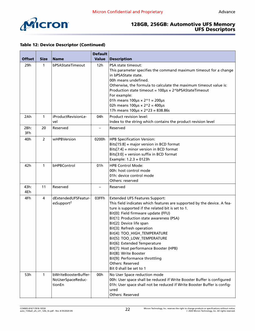
29h 1 bPSAStateTimeout 12h PSA state timeout:This parameter specifies the command maximum timeout for a changein bPSAState state.00h means undefined.Otherwise, the formula to calculate the maximum timeout value is:Production state timeout = 100µs × 2^bPSAStateTimeoutFor example:01h means 100µs × 2^1 = 200µs02h means 100µs × 2^2 = 400µs17h means 100µs × 2^23 = 838.86s
2Ah 1 iProductRevisionLe-vel
04h Product revision level:Index to the string which contains the product revision level
2Bh:3Fh
20 Reserved – Reserved
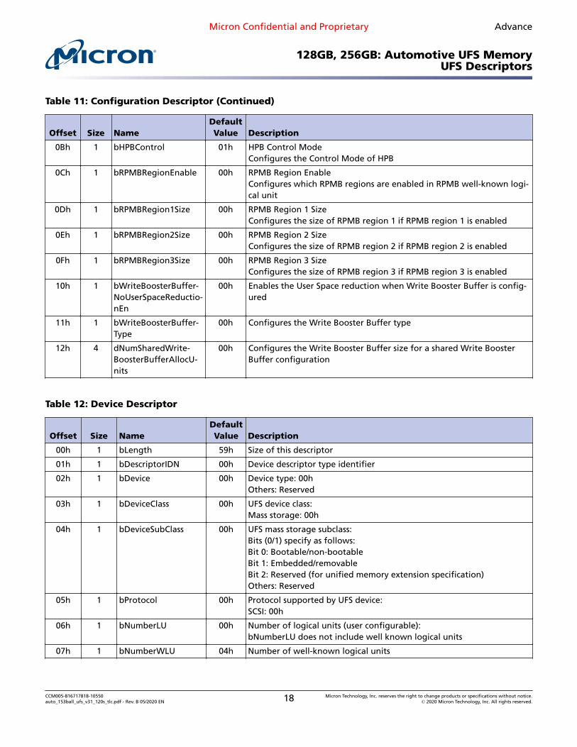
40h 2 wHPBVersion 0200h HPB Specification Version:Bits[15:8] = major version in BCD formatBits[7:4] = minor version in BCD formatBits[3:0] = version suffix in BCD formatExample: 1.2.3 = 0123h
42h 1 bHPBControl 01h HPB Control Mode:00h: host control mode01h: device control modeOthers: reserved
43h:4Eh
11 Reserved – Reserved
4Fh 4 dExtendedUFSFeatur-esSupport2
03FFh Extended UFS Features Support:This field indicates which features are supported by the device. A fea-ture is supported if the related bit is set to 1.Bit[0]: Field firmware update (FFU)Bit[1]: Production state awareness (PSA)Bit[2]: Device life spanBit[3]: Refresh operationBit[4]: TOO_HIGH_TEMPERATUREBit[5]: TOO_LOW_TEMPERATUREBit[6]: Extended TemperatureBit[7]: Host performance Booster (HPB)Bit[8]: Write BoosterBit[9]: Performance throttlingOthers: ReservedBit 0 shall be set to 1
53h 1 bWriteBoosterBuffer-NoUserSpaceReduc-tionEn
00h No User Space reduction mode00h: User space shall be reduced if Write Booster Buffer is configured01h: User space shall not be reduced if Write Booster Buffer is config-uredOthers: Reserved
CCM005-816717818-10550auto_153ball_ufs_v31_120s_tlc.pdf - Rev. B 05/2020 EN 22 Micron Technology, Inc. reserves the right to change products or specifications without notice.
00h Write Booster Buffer Type00h: LU dedicated buffer type01h: Single shared buffer typeOthers: Reserved
55h 4 dNumSharedWrite-BoosterBufferAllocU-nits
00h The Write Booster Buffer size for the shared Write Booster Buffer con-figuration
Notes: 1. Some fields are user-configurable as they can be configured by the user writing the con-figuration descriptor.
2. The Device Life Span and Write Booster features are supported as Jedec interface only
Table 13: Geometry Descriptor
Offset Size NameDefaultValue Description
00h 1 bLength 57h Size of this descriptor
01h 1 bDescriptorIDN 07h Geometry descriptor type identifier
02h 1 bMediaTechnology 00h Reserved
03h 1 Reserved 00h Reserved
04h 8 qTotalRaw-DeviceCa-pacity
128GB EE64000h Total raw device capacity:Total memory quantity available to the user to configure the de-vice logical units (RPMB excluded). It is expressed in unit of 512bytes.
256GB 1DCBC000h
0Ch 1 bMaxNumberLU 01h Maximum number of logical unit supported by the UFS device:01h: 32 logical units
0Dh 4 dSegmentSize 2000h Segment size:Value expressed in unit of 512 bytes
11h 1 bAllocationUnitSize 01h Allocation unit size:Value expressed in number of segments. Each logical unit can beallocated as a multiple of allocation units.
12h 1 bMinAddrBlockSize 08h Minimum addressable block size:Value expressed in unit of 512 bytes. Its minimum value is 08h,which corresponds to 4KB.
13h 1 bOptimalReadBlock-Size
80h Optimal read block size:Value expressed in unit of 512 bytes. This is optional parameter, 0= not available.
14h 1 bOptimalWriteBlock-Size
80h Optimal write block size:Value expressed in unit of 512 bytes
15h 1 bMaxInBufferSize 40h Maximum data-in buffer size:Value expressed in unit of 512 bytes. Its minimum value is 08h,which corresponds to 4KB.
CCM005-816717818-10550auto_153ball_ufs_v31_120s_tlc.pdf - Rev. B 05/2020 EN 23 Micron Technology, Inc. reserves the right to change products or specifications without notice.
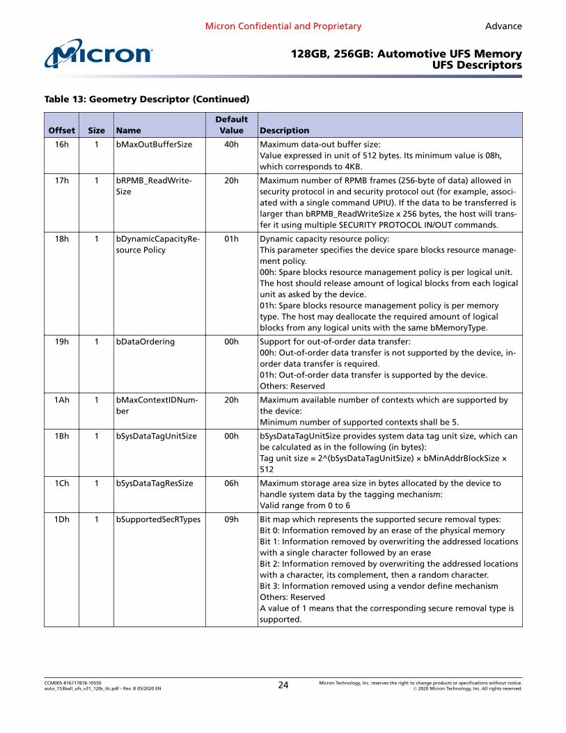
16h 1 bMaxOutBufferSize 40h Maximum data-out buffer size:Value expressed in unit of 512 bytes. Its minimum value is 08h,which corresponds to 4KB.
17h 1 bRPMB_ReadWrite-Size
20h Maximum number of RPMB frames (256-byte of data) allowed insecurity protocol in and security protocol out (for example, associ-ated with a single command UPIU). If the data to be transferred islarger than bRPMB_ReadWriteSize x 256 bytes, the host will trans-fer it using multiple SECURITY PROTOCOL IN/OUT commands.
18h 1 bDynamicCapacityRe-source Policy
01h Dynamic capacity resource policy:This parameter specifies the device spare blocks resource manage-ment policy.00h: Spare blocks resource management policy is per logical unit.The host should release amount of logical blocks from each logicalunit as asked by the device.01h: Spare blocks resource management policy is per memorytype. The host may deallocate the required amount of logicalblocks from any logical units with the same bMemoryType.
19h 1 bDataOrdering 00h Support for out-of-order data transfer:00h: Out-of-order data transfer is not supported by the device, in-order data transfer is required.01h: Out-of-order data transfer is supported by the device.Others: Reserved
1Ah 1 bMaxContextIDNum-ber
20h Maximum available number of contexts which are supported bythe device:Minimum number of supported contexts shall be 5.
1Bh 1 bSysDataTagUnitSize 00h bSysDataTagUnitSize provides system data tag unit size, which canbe calculated as in the following (in bytes):Tag unit size = 2^(bSysDataTagUnitSize) × bMinAddrBlockSize ×512
1Ch 1 bSysDataTagResSize 06h Maximum storage area size in bytes allocated by the device tohandle system data by the tagging mechanism:Valid range from 0 to 6
1Dh 1 bSupportedSecRTypes 09h Bit map which represents the supported secure removal types:Bit 0: Information removed by an erase of the physical memoryBit 1: Information removed by overwriting the addressed locationswith a single character followed by an eraseBit 2: Information removed by overwriting the addressed locationswith a character, its complement, then a random character.Bit 3: Information removed using a vendor define mechanismOthers: ReservedA value of 1 means that the corresponding secure removal type issupported.
CCM005-816717818-10550auto_153ball_ufs_v31_120s_tlc.pdf - Rev. B 05/2020 EN 24 Micron Technology, Inc. reserves the right to change products or specifications without notice.
8009h Bit map which represents the supported memory types:Bit 0: normal memory typeBit 1: System code memory typeBit 2: Non-persistent memory typeBit 3: Enhanced memory type 1Bit 4: Enhanced memory type 2Bit 5: Enhanced memory type 3Bit 6: Enhanced memory type 4Bit 7: Reserved…Bit 14: ReservedBit 15: RPMB memory typeA value 1 means that the corresponding memory type is suppor-ted. Bit 0 and Bit 15 shall be 1 for all UFS device.
20h 4 dSystemCodeMaxNAl-locU
– Not supported
24h 2 wSystemCodeCapAdj-Fac
–
26h 4 dNonPersistMaxNAllo-cU
–
2Ah 2 wNonPersistCapAdj-Fac
–
2Ch 4 dEn-hanced1MaxNAllocU
128GB 7732h Maximum number of allocation units for the enhanced memorytype 1256GB EE5Eh
30h 2 wEnhanced1CapA-djFac
0300h Capacity adjustment factor for the enhanced memory type 1
CCM005-816717818-10550auto_153ball_ufs_v31_120s_tlc.pdf - Rev. B 05/2020 EN 25 Micron Technology, Inc. reserves the right to change products or specifications without notice.
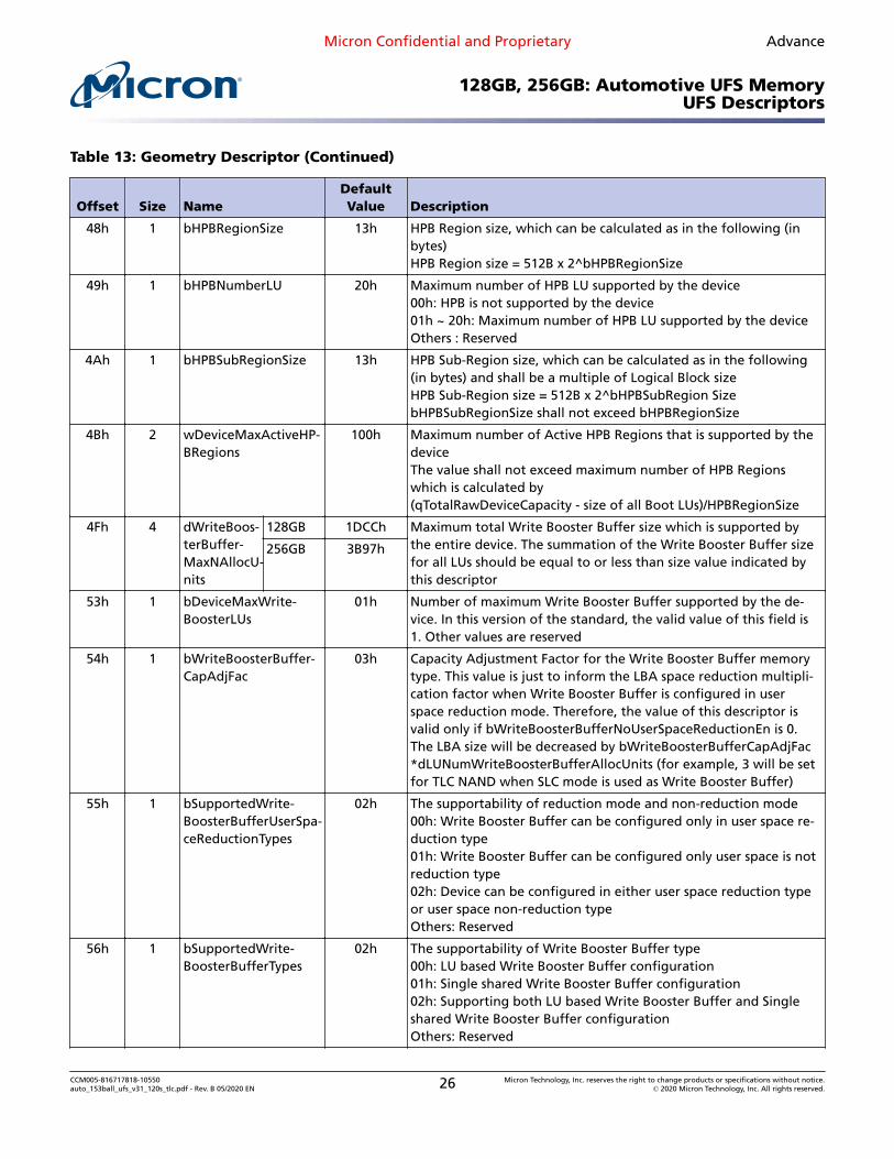
48h 1 bHPBRegionSize 13h HPB Region size, which can be calculated as in the following (inbytes)HPB Region size = 512B x 2^bHPBRegionSize
49h 1 bHPBNumberLU 20h Maximum number of HPB LU supported by the device00h: HPB is not supported by the device01h ~ 20h: Maximum number of HPB LU supported by the deviceOthers : Reserved
4Ah 1 bHPBSubRegionSize 13h HPB Sub-Region size, which can be calculated as in the following(in bytes) and shall be a multiple of Logical Block sizeHPB Sub-Region size = 512B x 2^bHPBSubRegion SizebHPBSubRegionSize shall not exceed bHPBRegionSize
4Bh 2 wDeviceMaxActiveHP-BRegions
100h Maximum number of Active HPB Regions that is supported by thedeviceThe value shall not exceed maximum number of HPB Regionswhich is calculated by(qTotalRawDeviceCapacity - size of all Boot LUs)/HPBRegionSize
4Fh 4 dWriteBoos-terBuffer-MaxNAllocU-nits
128GB 1DCCh Maximum total Write Booster Buffer size which is supported bythe entire device. The summation of the Write Booster Buffer sizefor all LUs should be equal to or less than size value indicated bythis descriptor
256GB 3B97h
53h 1 bDeviceMaxWrite-BoosterLUs
01h Number of maximum Write Booster Buffer supported by the de-vice. In this version of the standard, the valid value of this field is1. Other values are reserved
54h 1 bWriteBoosterBuffer-CapAdjFac
03h Capacity Adjustment Factor for the Write Booster Buffer memorytype. This value is just to inform the LBA space reduction multipli-cation factor when Write Booster Buffer is configured in userspace reduction mode. Therefore, the value of this descriptor isvalid only if bWriteBoosterBufferNoUserSpaceReductionEn is 0.The LBA size will be decreased by bWriteBoosterBufferCapAdjFac*dLUNumWriteBoosterBufferAllocUnits (for example, 3 will be setfor TLC NAND when SLC mode is used as Write Booster Buffer)
02h The supportability of reduction mode and non-reduction mode00h: Write Booster Buffer can be configured only in user space re-duction type01h: Write Booster Buffer can be configured only user space is notreduction type02h: Device can be configured in either user space reduction typeor user space non-reduction typeOthers: Reserved
56h 1 bSupportedWrite-BoosterBufferTypes
02h The supportability of Write Booster Buffer type00h: LU based Write Booster Buffer configuration01h: Single shared Write Booster Buffer configuration02h: Supporting both LU based Write Booster Buffer and Singleshared Write Booster Buffer configurationOthers: Reserved
CCM005-816717818-10550auto_153ball_ufs_v31_120s_tlc.pdf - Rev. B 05/2020 EN 26 Micron Technology, Inc. reserves the right to change products or specifications without notice.
01h 1 bDescriptorIDN 02h Unit descriptor type identifier
02h 1 bUnitIndex 00h to1Fh
Unit index
03h 1 bLUEnable 00h Logical unit enable (user configurable):00h: Logical unit disabled01h: Logical unit enabledOthers: Reserved
04h 1 bBootLunID 00h Boot LUN ID (user configurable):00h: Not bootable01h: Boot LU A02h: Boot LU BOthers: Reserved
05h 1 BLUWriteProtect 00h Logical unit write protect (user configurable):00h: LU not write protected01h: LU write protected when fPowerOnWPEn = 102h: LU permanently write protected when fPermanentWPEn = 103h: Reserved (for UFS Security Extension specification)Others: Reserved
06h 1 bLUQueueDepth 00h Logical unit queue depth:Queue depth available in this LU. Queue depth of 0 means best effortby device to service the command task.
07h 1 bPSASensitive 01h 00h: LU is not sensitive to soldering01h: LU is sensitive to solderingOthers: Reserved
08h 1 bMemoryType 00h Memory type defines the logical unit memory type (user configurable):00h: Normal memory01h: System code memory type02h: Non-persistent memory type03h: Enhanced memory type 104h: Enhanced memory type 205h: Enhanced memory type 306h: Enhanced memory type 4Others: Reserved
09h 1 bDataReliability 00h Data reliability (user configurable):00h: The logical unit is not protected. Logical unit's entire data mightbe lost as a result of a power failure during a WRITE operation.01h: The logical unit is protected. Logical unit's data is protectedagainst power failure.Others: Reserved
0Ah 1 bLogicalBlockSize 0Ch Logical block size (user configurable):0Ch (minimum value which corresponds to 4KB)–0Fh
CCM005-816717818-10550auto_153ball_ufs_v31_120s_tlc.pdf - Rev. B 05/2020 EN 27 Micron Technology, Inc. reserves the right to change products or specifications without notice.
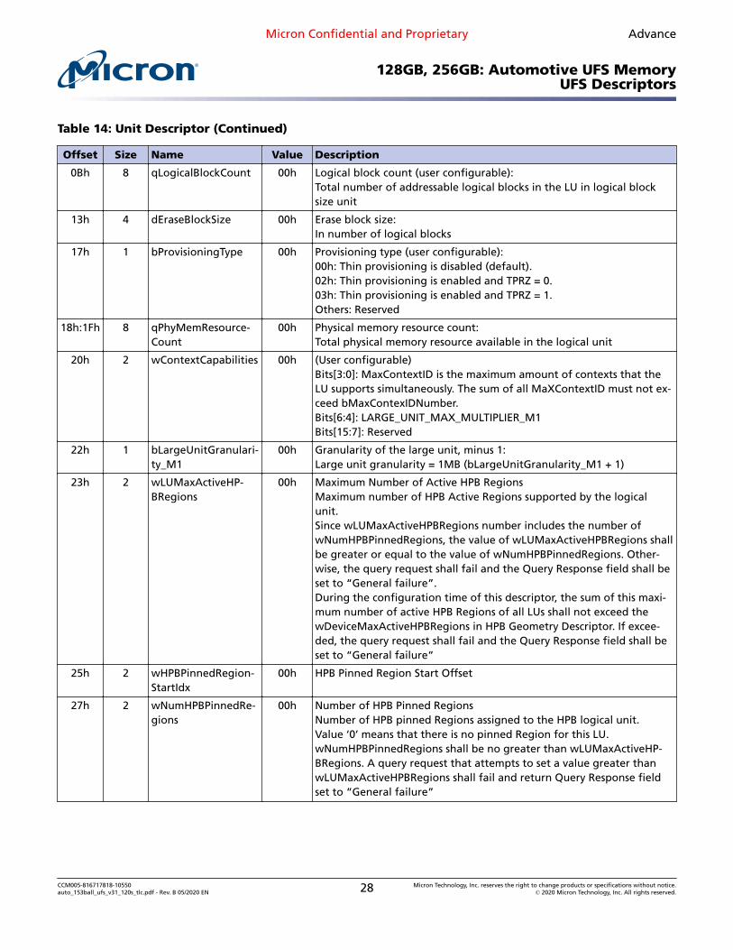
0Bh 8 qLogicalBlockCount 00h Logical block count (user configurable):Total number of addressable logical blocks in the LU in logical blocksize unit
13h 4 dEraseBlockSize 00h Erase block size:In number of logical blocks
17h 1 bProvisioningType 00h Provisioning type (user configurable):00h: Thin provisioning is disabled (default).02h: Thin provisioning is enabled and TPRZ = 0.03h: Thin provisioning is enabled and TPRZ = 1.Others: Reserved
18h:1Fh 8 qPhyMemResource-Count
00h Physical memory resource count:Total physical memory resource available in the logical unit
20h 2 wContextCapabilities 00h (User configurable)Bits[3:0]: MaxContextID is the maximum amount of contexts that theLU supports simultaneously. The sum of all MaXContextID must not ex-ceed bMaxContexIDNumber.Bits[6:4]: LARGE_UNIT_MAX_MULTIPLIER_M1Bits[15:7]: Reserved
22h 1 bLargeUnitGranulari-ty_M1
00h Granularity of the large unit, minus 1:Large unit granularity = 1MB (bLargeUnitGranularity_M1 + 1)
23h 2 wLUMaxActiveHP-BRegions
00h Maximum Number of Active HPB RegionsMaximum number of HPB Active Regions supported by the logicalunit.Since wLUMaxActiveHPBRegions number includes the number ofwNumHPBPinnedRegions, the value of wLUMaxActiveHPBRegions shallbe greater or equal to the value of wNumHPBPinnedRegions. Other-wise, the query request shall fail and the Query Response field shall beset to “General failure”.During the configuration time of this descriptor, the sum of this maxi-mum number of active HPB Regions of all LUs shall not exceed thewDeviceMaxActiveHPBRegions in HPB Geometry Descriptor. If excee-ded, the query request shall fail and the Query Response field shall beset to “General failure”
25h 2 wHPBPinnedRegion-StartIdx
00h HPB Pinned Region Start Offset
27h 2 wNumHPBPinnedRe-gions
00h Number of HPB Pinned RegionsNumber of HPB pinned Regions assigned to the HPB logical unit.Value ‘0’ means that there is no pinned Region for this LU.wNumHPBPinnedRegions shall be no greater than wLUMaxActiveHP-BRegions. A query request that attempts to set a value greater thanwLUMaxActiveHPBRegions shall fail and return Query Response fieldset to “General failure”
CCM005-816717818-10550auto_153ball_ufs_v31_120s_tlc.pdf - Rev. B 05/2020 EN 28 Micron Technology, Inc. reserves the right to change products or specifications without notice.
CCM005-816717818-10550auto_153ball_ufs_v31_120s_tlc.pdf - Rev. B 05/2020 EN 29 Micron Technology, Inc. reserves the right to change products or specifications without notice.
CCM005-816717818-10550auto_153ball_ufs_v31_120s_tlc.pdf - Rev. B 05/2020 EN 30 Micron Technology, Inc. reserves the right to change products or specifications without notice.
CCM005-816717818-10550auto_153ball_ufs_v31_120s_tlc.pdf - Rev. B 05/2020 EN 31 Micron Technology, Inc. reserves the right to change products or specifications without notice.
01h 1 bDescriptorIDN 05h String descriptor type identifier
02h 2 UC[0] – Unicode string character
04h 2 UC[1] – Unicode string character
06h 2 UC[2] – Unicode string character
08h 2 UC[3] – Unicode string character
Table 23: Device Health Descriptor
Offset Size Name Value Description
00h 1 bLength 2Dh Size of this descriptor
01h 1 bDescriptorIDN 09h Device health descriptor type identifier
02h 1 bPreEOLInfo 01h Pre end-of-life information provides indication about device life timereflected by average reserved blocks:01h: Normal
03h 1 bDeviceLifeTimeEstA 01h This field provides an indication of the device life time based on theamount of performed PROGRAM/ERASE cycles. The calculation methodis vendor specific and referred as method A.01h: 0%–10% device life time used
04h 1 bDeviceLifeTimeEstB 01h This field provides an indication of the device life time based on theamount of performed PROGRAM/ERASE cycles. The calculation methodis vendor specific and referred as method B.01h: 0%–10% device life time used
05h 32 VendorPropInfo 01h Reserved for vendor proprietary health report
24h 1 VendorPropInfoTlcEC 01h Reserved for vendor proprietary health report
CCM005-816717818-10550auto_153ball_ufs_v31_120s_tlc.pdf - Rev. B 05/2020 EN 32 Micron Technology, Inc. reserves the right to change products or specifications without notice.
25h 3 dRefreshTotalCount 00h Total Refresh CountIndicates how many times the device complete refresh for the entiredevice; incremented by 1 when dRefreshProgress reach 100000
29h 4 dRefreshProgress 00h Refresh ProgressIndicates the refresh progress in %.
CCM005-816717818-10550auto_153ball_ufs_v31_120s_tlc.pdf - Rev. B 05/2020 EN 33 Micron Technology, Inc. reserves the right to change products or specifications without notice.
UFS Flags, Attributes, and CommandsA flag is a single boolean value that represents 0 or 1 type of value. Flags are useful toenable or disable certain functions, modes, or states with the device.
Table 24: Flags
IDN Name TypeDefaultValue Description
00h Reserved – – Reserved
01h fDeviceInit Read/Set only
00h Device initialization:0b: Device initialization completed or not started yet1b: Device initialization in progress
04h FBackgroundOpsEn Read/Volatile 01h Background operations enable:00h: Device is not permitted to run background operations01h: Device is permitted to run background operations
05h fDeviceLifeSpan-ModeEn
Read/Volatile 00h Device life span mode:0b: Device life span mode is disabled1b: Device life span mode is enabled
06h fPurgeEnable Write only/Volatile
– PURGE enable:00h: PURGE operation is disabled01h: PURGE operation is enabled
07h fRefreshEnable Write only/Volatile
– Refresh Enable:0b: Refresh operation is disabled.1b: Refresh operation is enabled
08h fPhyResourceRemoval Read/Persistent
00h Physical resource removal:The host sets this flag to 1 to indicate that the dynamic ca-pacity operation commences upon device EndPointReset orhardware reset.The device resets this flag to 0 after completion of dynamiccapacity operation. The host cannot reset this flag.
09h fBusyRTC Read only 00h Busy real-time clock:00h: Device is not executing internal operation related toRTC01h: Device is executing internal operation related to RTC
0Ah Reserved – – Reserved for unified memory extension standard
0Bh fPermanentlyDisableF-WUpdate
Read/Write once
00h Permanently disable firmware update:00h: The UFS device firmware may be modified.01h: The UFS device permanently disallows future firmwareupdates to the UFS device.
0Ch Reserved – – Reserved for unified memory extension standard
0Dh Reserved – – Reserved for unified memory extension standard
Micron Confidential and Proprietary Advance
128GB, 256GB: Automotive UFS MemoryUFS Flags, Attributes, and Commands
CCM005-816717818-10550auto_153ball_ufs_v31_120s_tlc.pdf - Rev. B 05/2020 EN 34 Micron Technology, Inc. reserves the right to change products or specifications without notice.
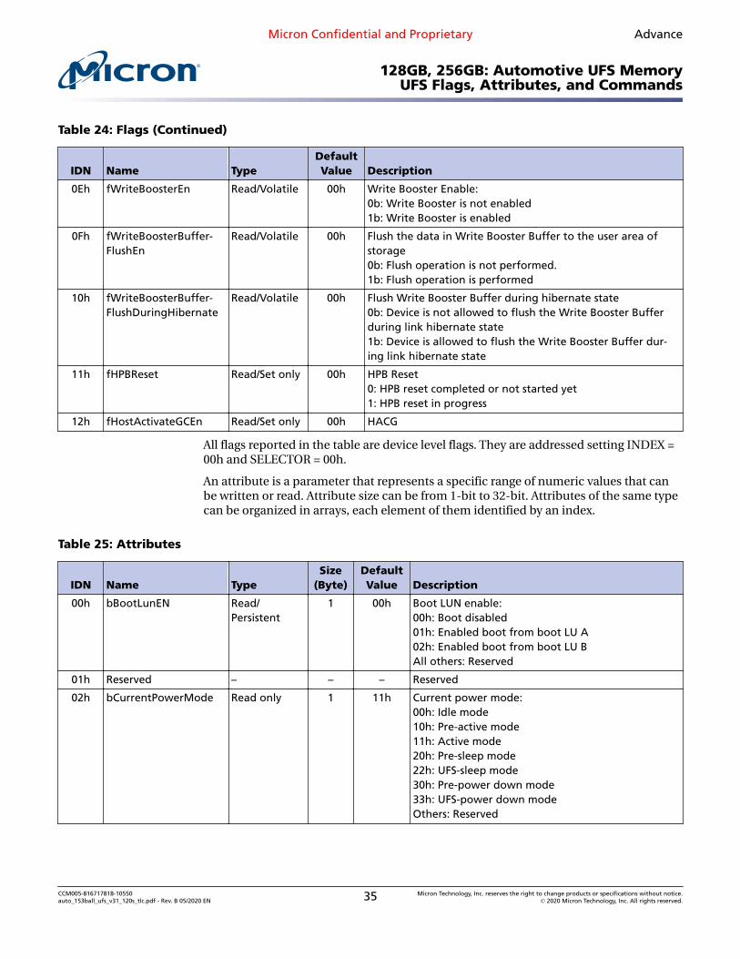
0Eh fWriteBoosterEn Read/Volatile 00h Write Booster Enable:0b: Write Booster is not enabled1b: Write Booster is enabled
0Fh fWriteBoosterBuffer-FlushEn
Read/Volatile 00h Flush the data in Write Booster Buffer to the user area ofstorage0b: Flush operation is not performed.1b: Flush operation is performed
10h fWriteBoosterBuffer-FlushDuringHibernate
Read/Volatile 00h Flush Write Booster Buffer during hibernate state0b: Device is not allowed to flush the Write Booster Bufferduring link hibernate state1b: Device is allowed to flush the Write Booster Buffer dur-ing link hibernate state
11h fHPBReset Read/Set only 00h HPB Reset0: HPB reset completed or not started yet1: HPB reset in progress
12h fHostActivateGCEn Read/Set only 00h HACG
All flags reported in the table are device level flags. They are addressed setting INDEX =00h and SELECTOR = 00h.
An attribute is a parameter that represents a specific range of numeric values that canbe written or read. Attribute size can be from 1-bit to 32-bit. Attributes of the same typecan be organized in arrays, each element of them identified by an index.
Table 25: Attributes
IDN Name TypeSize
(Byte)DefaultValue Description
00h bBootLunEN Read/Persistent
1 00h Boot LUN enable:00h: Boot disabled01h: Enabled boot from boot LU A02h: Enabled boot from boot LU BAll others: Reserved
01h Reserved – – – Reserved
02h bCurrentPowerMode Read only 1 11h Current power mode:00h: Idle mode10h: Pre-active mode11h: Active mode20h: Pre-sleep mode22h: UFS-sleep mode30h: Pre-power down mode33h: UFS-power down modeOthers: Reserved
Micron Confidential and Proprietary Advance
128GB, 256GB: Automotive UFS MemoryUFS Flags, Attributes, and Commands
CCM005-816717818-10550auto_153ball_ufs_v31_120s_tlc.pdf - Rev. B 05/2020 EN 35 Micron Technology, Inc. reserves the right to change products or specifications without notice.
03h bActiveICCLevel Read/Volatile 1 00h Active ICC level:bActiveICCLevel defines the maximum current con-sumption allowed during active mode.00h: Lowest active ICC level0Fh: Highest active ICC levelOthers: Reserved
04h bOutOfOrderDataEn Read/Write once
1 00h Out-of-order data transfer enable:00h: Out-of-order data transfer is disabled01h: Out-of-order data transfer is enabledOthers: Reserved
05h bBackgroundOpStatus Read only 1 00h Background operations status device health statusfor background operation:00h: Not required01h: Required, not critical02h: Required, performance impact03h: CriticalOthers: Reserved
06h bPurgeStatus Read only 1 00h PURGE operation status:00h: Idle (PURGE operation disabled)01h: PURGE operation in progress02h: PURGE operation stopped prematurely03h: PURGE operation completed successfully04h: PURGE operation failed due to logical unitqueue not empty05h: PURGE operation general failureOthers: Reserved
07h bMaxDataInSize Read/Persistent
1 40h Maximum data in size
08h bMaxDataOutSize Read/Persistent
1 40h Maximum data out size
09h dDynCapNeeded Read only 4 00h Dynamic capacity needed
1 02h Maximum current number of outstanding RTTs indevice that is allowed.
Micron Confidential and Proprietary Advance
128GB, 256GB: Automotive UFS MemoryUFS Flags, Attributes, and Commands
CCM005-816717818-10550auto_153ball_ufs_v31_120s_tlc.pdf - Rev. B 05/2020 EN 36 Micron Technology, Inc. reserves the right to change products or specifications without notice.
0Eh wExceptionEventStatus Read only 2 00h Bit 0: DYNCAP_NEEDEDBit 1: SYSPOOL_EXHAUSTEDBit 2: URGENT_BKOPSBit 3–15: Reserved
0Fh dSecondsPassed Write only 4 00h Bits[31:0]: Seconds passed from TIME BASELINE
10h wContextConf Read/Volatile 2 00h INDEX specifies the LU number. SELECTOR specifiesthe context ID within the LU. Valid values are 01h–Fh
11h Obsolete – – – –
12h Reserved – – – Reserved for Unified Memory Extension standard
13h bHostActivateGCStatus – 1 00h HAGC
14h bDeviceFFUStatus Read only 1 00h Device FFU status:00h: No information01h: Successful microcode update02h: Microcode corruption error03h: Internal error04h: Microcode version mismatch05h–FEh: ReservedFFh: General error
15h bPSAState Read/Persistent
1 00h 00h: Off. PSA feature is off.01h: Pre-soldering. PSA feature is on, device is in thepre-soldering state.02h: Loading complete. PSA feature is on. The hostwill set to this value after the host finished writingdata during pre-soldering state.03h: Soldered. PSA feature is no longer available.Set by the device to indicate it is in post-solderingstate. This attribute unchangeable after it is in sol-dered state.
16h dPSADataSize Read/Persistent
4 00h The amount of data that the host plans to load toall logical units with bPSASensitive set to 1.
Micron Confidential and Proprietary Advance
128GB, 256GB: Automotive UFS MemoryUFS Flags, Attributes, and Commands
CCM005-816717818-10550auto_153ball_ufs_v31_120s_tlc.pdf - Rev. B 05/2020 EN 37 Micron Technology, Inc. reserves the right to change products or specifications without notice.
Read only 1 05h Minimum time for which the reference clock is re-quired by device during transition to LS-MODE orHIBERN8 state. The larger time requirement amongthe transition to LS-MODE and HIBERN8 statesshould be set for this attribute.00h: Undefined01h: 1 micro second…FFh: 255 micro seconds
18h bDeviceCaseRoughT-emperature
Read only 1 00h Device’s rough package case surface temperature.This value is valid when (TOO_HIGH_TEMPERATUREis supported and TOO_HIGH_TEMP_EN is enabled)or ( TOO_LOW_TEMPERATURE is supported andTOO_LOW_TEMP_EN is enabled ).0 : Unknown Temperature1~250 : ( this value – 80 ) degrees in Celsius. (–79ºC~170 ºC )Others: Reserved
19h bDeviceTooHighTemp-Boundary
Read only 1 BCh High temperature boundary from whichTOO_HIGH_TEMP in wExceptionEventStatus isturned on.0: Unknown100~250: ( this value – 80 ) degrees in celcius. (20ºC~170 ºC )Others: Reserved
1Ah bDeviceTooLowTemp-Boundary
Read only 1 2Bh Low temperature boundary from whichTOO_LOW_TEMP in wExceptionEventStatus isturned on.0: Unknown1~80: ( this value – 80 ) degrees in celcius. (–79 ºC~0ºC )Others: Reserved
1Bh bTrottling_Status Read only 1 00h
Micron Confidential and Proprietary Advance
128GB, 256GB: Automotive UFS MemoryUFS Flags, Attributes, and Commands
CCM005-816717818-10550auto_153ball_ufs_v31_120s_tlc.pdf - Rev. B 05/2020 EN 38 Micron Technology, Inc. reserves the right to change products or specifications without notice.
Read only 1 00h Flush operation status of Write Booster Buffer00h: idle. Device is not flushing the Write BoosterBuffer; either the Write Booster Buffer is empty or aflush has not been initiated01h: Flush operation in progress. The Write BoosterBuffer is not yet empty and a flush has been initi-ated02h: Flush operation stopped prematurely. TheWrite Booster Buffer is not empty and the host stop-ped the in-progress flush03h: Flush operation completed successfully04h: Flush operation general failureOthers: Reserved
1Dh bAvailableWriteBoos-terBufferSize
Read only 1 00h Available Write Booster Buffer SizeThis available buffer size is decreased by Write Boos-ter operation and increased by flush operationValue expressed in unit of 10% granularity00h: 0% buffer remains01h: 10% buffer remains02h~09h: 20%~90% buffer remains0Ah: 100% buffer remainsOthers: Reserved
1Eh bWriteBoosterBufferLi-feTimeEst
Read only 1 00h This field provides an indication of the Write Boos-ter Buffer lifetime based on the amount of per-formed program/erase cycles. The detailed calcula-tion method is vendor specific00h: Information not available (Write Booster Bufferis disabled)01h: 0%–10% Write Booster Buffer life time used02h: 10%–20% Write Booster Buffer life time used03h: 20%–30% Write Booster Buffer life time used04h: 30%–40% Write Booster Buffer life time used05h: 40%–50% Write Booster Buffer life time used06h: 50%–60% Write Booster Buffer life time used07h: 60%–70% Write Booster Buffer life time used08h: 70%–80% Write Booster Buffer life time used09h: 80%–90% Write Booster Buffer life time used0Ah: 90%–100% Write Booster Buffer life time used0Bh: Exceeded its maximum estimated Write Boos-ter Buffer life time (write commands are processedas if Write Booster feature was disabled)Others: Reserved
Micron Confidential and Proprietary Advance
128GB, 256GB: Automotive UFS MemoryUFS Flags, Attributes, and Commands
CCM005-816717818-10550auto_153ball_ufs_v31_120s_tlc.pdf - Rev. B 05/2020 EN 39 Micron Technology, Inc. reserves the right to change products or specifications without notice.
Read only 4 00h The current Write Booster Buffer sizeHost can check the current Write Booster Buffer sizeby checking this attribute. Value expressed in unit ofAllocation Units. If this value is 0, then the currentWrite Booster Buffer size is 0
20h:2Bh
Reserved – – – Reserved for Unified Memory Extension standard
2Ch bRefreshStatus Read only 1 00h Refresh Operation Status00h: Idle (refresh operation disabled)01h: Refresh operation in progress02h: Refresh operation stopped prematurely03h: Refresh operation completed successfully04h: Refresh operation failed due to logical unitqueue not empty05h: Refresh operation general failureOthers: Reserved
2Dh bRefreshFreq Read/Persistent
1 00h Refresh FrequencyHost should make sure that dRefreshTotalCount willbe incremented on this frequency00h: Not defined01h: 1 month02h: 2 month…FFh: 255 month
2Eh bRefreshUnit Read/Persistent
1 00h Refresh Operation UnitThis attribute may be set to adjust the minimumphysical block numbers to be refreshed upon a sin-gle request00h: Minimum refresh capability of Device01h:100% (entire device)Others: Reserved
2Fh bRefreshMethod Read/Persistent
1 00h Refresh MethodThis parameter specifies the refresh operation meth-od00h: Not defined01h: Manual-Force02h: Manual-SelectiveOthers: Reserved
Notes: 1. dDynCapNeeded and wContextConf are arrays of attributes.2. Default value means attribute's value after device manufacturing.
Micron Confidential and Proprietary Advance
128GB, 256GB: Automotive UFS MemoryUFS Flags, Attributes, and Commands
CCM005-816717818-10550auto_153ball_ufs_v31_120s_tlc.pdf - Rev. B 05/2020 EN 40 Micron Technology, Inc. reserves the right to change products or specifications without notice.
128GB, 256GB: Automotive UFS MemoryUFS Flags, Attributes, and Commands
CCM005-816717818-10550auto_153ball_ufs_v31_120s_tlc.pdf - Rev. B 05/2020 EN 41 Micron Technology, Inc. reserves the right to change products or specifications without notice.
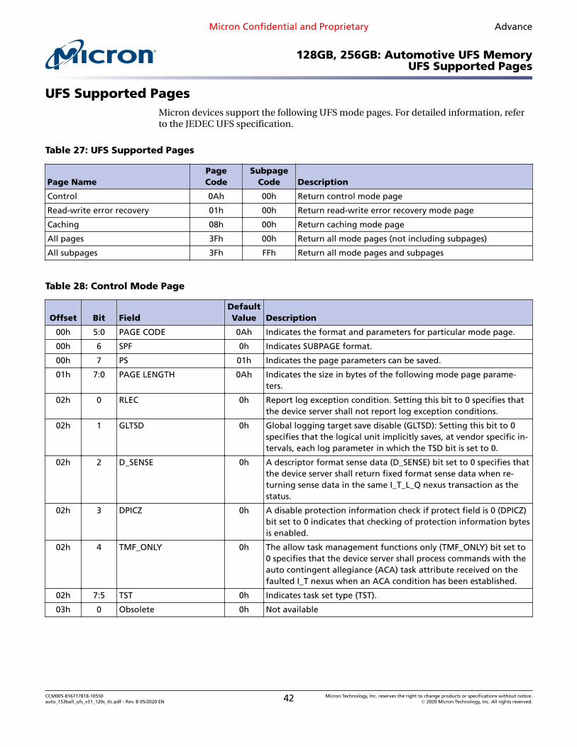
All pages 3Fh 00h Return all mode pages (not including subpages)
All subpages 3Fh FFh Return all mode pages and subpages
Table 28: Control Mode Page
Offset Bit FieldDefaultValue Description
00h 5:0 PAGE CODE 0Ah Indicates the format and parameters for particular mode page.
00h 6 SPF 0h Indicates SUBPAGE format.
00h 7 PS 01h Indicates the page parameters can be saved.
01h 7:0 PAGE LENGTH 0Ah Indicates the size in bytes of the following mode page parame-ters.
02h 0 RLEC 0h Report log exception condition. Setting this bit to 0 specifies thatthe device server shall not report log exception conditions.
02h 1 GLTSD 0h Global logging target save disable (GLTSD): Setting this bit to 0specifies that the logical unit implicitly saves, at vendor specific in-tervals, each log parameter in which the TSD bit is set to 0.
02h 2 D_SENSE 0h A descriptor format sense data (D_SENSE) bit set to 0 specifies thatthe device server shall return fixed format sense data when re-turning sense data in the same I_T_L_Q nexus transaction as thestatus.
02h 3 DPICZ 0h A disable protection information check if protect field is 0 (DPICZ)bit set to 0 indicates that checking of protection information bytesis enabled.
02h 4 TMF_ONLY 0h The allow task management functions only (TMF_ONLY) bit set to0 specifies that the device server shall process commands with theauto contingent allegiance (ACA) task attribute received on thefaulted I_T nexus when an ACA condition has been established.
CCM005-816717818-10550auto_153ball_ufs_v31_120s_tlc.pdf - Rev. B 05/2020 EN 42 Micron Technology, Inc. reserves the right to change products or specifications without notice.
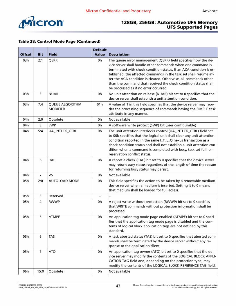
03h 2:1 QERR 0h The queue error management (QERR) field specifies how the de-vice server shall handle other commands when one command isterminated with check condition status. If an ACA condition is es-tablished, the affected commands in the task set shall resume af-ter the ACA condition is cleared. Otherwise, all commands otherthan the command that received the check condition status shallbe processed as if no error occurred.
03h 3 NUAR 0h No unit attention on release (NUAR) bit set to 0 specifies that thedevice server shall establish a unit attention condition.
03h 7:4 QUEUE ALGORITHMMODIFIER
01h A value of 1 in this field specifies that the device server may reor-der the processing sequence of commands having the SIMPLE taskattribute in any manner.
04h 2:0 Obsolete 0h Not available
04h 3 SWP 0h A software write protect (SWP) bit (user configurable)
04h 5:4 UA_INTLCK_CTRL 0h The unit attention interlocks control (UA_INTLCK_CTRL) field setto 00b specifies that the logical unit shall clear any unit attentioncondition reported in the same I_T_L_Q nexus transaction as acheck condition status and shall not establish a unit attention con-dition when a command is completed with busy, task set full, orreservation conflict status.
04h 6 RAC 0h A report a check (RAC) bit set to 0 specifies that the device servermay return busy status regardless of the length of time the reasonfor returning busy status may persist.
04h 7 VS 0h Not available
05h 2:0 AUTOLOAD MODE 0h This field specifies the action to be taken by a removable mediumdevice server when a medium is inserted. Setting it to 0 meansthat medium shall be loaded for full access.
05h 3 Reserved – –
05h 4 RWWP 0h A reject write without protection (RWWP) bit set to 0 specifiesthat WRITE commands without protection information shall beprocessed.
05h 5 ATMPE 0h An application tag mode page enabled (ATMPE) bit set to 0 speci-fies that the application tag mode page is disabled and the con-tents of logical block application tags are not defined by thisstandard.
05h 6 TAS 0h A task aborted status (TAS) bit set to 0 specifies that aborted com-mands shall be terminated by the device server without any re-sponse to the application client.
05h 7 ATO 0h An application tag owner (ATO) bit set to 0 specifies that the de-vice server may modify the contents of the LOGICAL BLOCK APPLI-CATION TAG field and, depending on the protection type, maymodify the contents of the LOGICAL BLOCK REFERENCE TAG field.
CCM005-816717818-10550auto_153ball_ufs_v31_120s_tlc.pdf - Rev. B 05/2020 EN 43 Micron Technology, Inc. reserves the right to change products or specifications without notice.
0h This field contains advisory data that is the time in seconds thatthe device server requires to complete an extended self-test whenthe device server is not interrupted by subsequent commands andno errors occur during processing of the self-test.
Note: 1. Some fields are user-configurable.
Table 29: Read – Write Error Recovery Mode Page
Offset Bit FieldDefaultValue Description
00h 5:0 PAGE CODE 01h Indicates the format and parameters for particular mode page.
00h 6 SPF 0h Indicates SUBPAGE format.
00h 7 PS 01h Indicates the page parameters can be saved.
01h 7:0 PAGE LENGTH 0Ah Indicates the size in bytes of the following mode page parame-ters.
02h 0 DCR 0h A disable correction (DCR) bit set to 0 allows the use of additionalinformation (for example, ECC bytes) for data error recovery. If theEER bit is set to 1, the DCR bit shall be set to 0.
02h 1 DTE 0h A data terminate on error (DTE) bit set to 0 specifies that the de-vice server shall not terminate the data-in or data-out buffertransfer of a command performing a READ or WRITE operationupon detection of a recovered error.
02h 2 PER 0h A post error (PER) bit set to 0 specifies that if a recovered read er-ror occurs during a command performing a READ or WRITE opera-tion, then the device server shall perform error recovery proce-dures within the limits established by the error recovery parame-ters and only terminate the command with check condition statusif the error becomes uncorrectable based on the established limits.If the DTE bit is set to 1, then the PER bit shall be set to 1.
02h 3 EER 0h An enable early recovery (EER) bit set to 0 specifies that the deviceserver shall use an error recovery procedure that minimizes therisk of error mis-detection or mis-correction.
02h 4 RC 0h A read continuous (RC) bit set to 0 specifies that ERROR RECOV-ERY operations that cause delays during the data transfer are ac-ceptable. Data shall not be fabricated.
02h 5 TB 0h A transfer block (TB) bit set to 0 specifies that if an unrecoveredread error occurs during a READ operation, then the device servershall not transfer any data for the logical block to the data-in buf-fer.
CCM005-816717818-10550auto_153ball_ufs_v31_120s_tlc.pdf - Rev. B 05/2020 EN 44 Micron Technology, Inc. reserves the right to change products or specifications without notice.
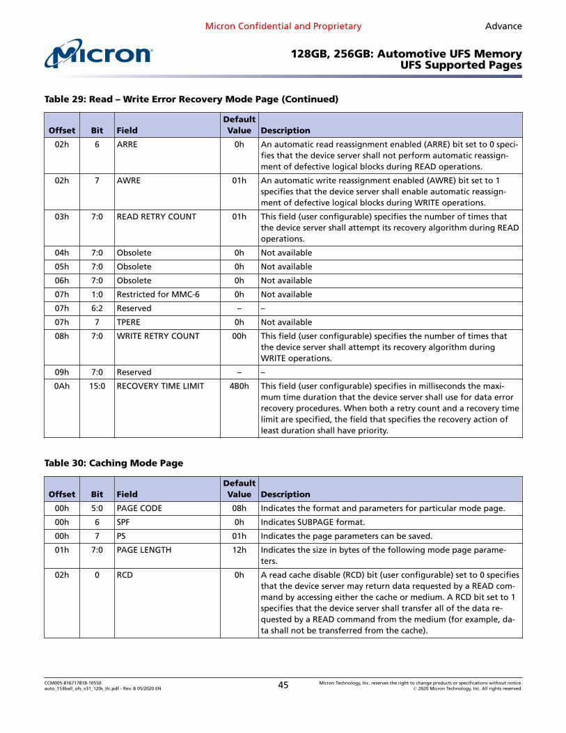
02h 6 ARRE 0h An automatic read reassignment enabled (ARRE) bit set to 0 speci-fies that the device server shall not perform automatic reassign-ment of defective logical blocks during READ operations.
02h 7 AWRE 01h An automatic write reassignment enabled (AWRE) bit set to 1specifies that the device server shall enable automatic reassign-ment of defective logical blocks during WRITE operations.
03h 7:0 READ RETRY COUNT 01h This field (user configurable) specifies the number of times thatthe device server shall attempt its recovery algorithm during READoperations.
04h 7:0 Obsolete 0h Not available
05h 7:0 Obsolete 0h Not available
06h 7:0 Obsolete 0h Not available
07h 1:0 Restricted for MMC-6 0h Not available
07h 6:2 Reserved – –
07h 7 TPERE 0h Not available
08h 7:0 WRITE RETRY COUNT 00h This field (user configurable) specifies the number of times thatthe device server shall attempt its recovery algorithm duringWRITE operations.
09h 7:0 Reserved – –
0Ah 15:0 RECOVERY TIME LIMIT 4B0h This field (user configurable) specifies in milliseconds the maxi-mum time duration that the device server shall use for data errorrecovery procedures. When both a retry count and a recovery timelimit are specified, the field that specifies the recovery action ofleast duration shall have priority.
Table 30: Caching Mode Page
Offset Bit FieldDefaultValue Description
00h 5:0 PAGE CODE 08h Indicates the format and parameters for particular mode page.
00h 6 SPF 0h Indicates SUBPAGE format.
00h 7 PS 01h Indicates the page parameters can be saved.
01h 7:0 PAGE LENGTH 12h Indicates the size in bytes of the following mode page parame-ters.
02h 0 RCD 0h A read cache disable (RCD) bit (user configurable) set to 0 specifiesthat the device server may return data requested by a READ com-mand by accessing either the cache or medium. A RCD bit set to 1specifies that the device server shall transfer all of the data re-quested by a READ command from the medium (for example, da-ta shall not be transferred from the cache).
CCM005-816717818-10550auto_153ball_ufs_v31_120s_tlc.pdf - Rev. B 05/2020 EN 45 Micron Technology, Inc. reserves the right to change products or specifications without notice.
02h 1 MF 0h A multiplication factor (MF) bit set to 0 specifies that the deviceserver shall interpret the MINIMUM PREFETCH field and the MAXI-MUM PREFETCH field in terms of the number of logical blocks foreach of the respective types of prefetch.
02h 2 WCE 01h A write back cache enable (WCE) bit (user configurable) set to 0specifies that the device server shall complete a WRITE commandwith good status only after writing all of the data to the mediumwithout error. A WCE bit set to 1 specifies that the device servermay complete a WRITE command with good status after receivingthe data without error and prior to having written the data to themedium.
02h 3 SIZE 0h A size enable (SIZE) bit set to 0 specifies that the NUMBER OFCACHE SEGMENTS field is used to control caching segmentation.Simultaneous use of both the number of segments and the seg-ment size is vendor specific.
02h 4 DISC 0h A discontinuity (DISC) bit set to 0 specifies that prefetches be trun-cated or wrapped at time discontinuities.
02h 5 CAP 0h A caching analysis permitted (CAP) bit set to 0 specifies that cach-ing analysis is disabled (for example, to reduce overhead time orto prevent non-pertinent operations from impacting tuning val-ues).
02h 6 ABPF 0h An abort prefetch (ABPF) bit set to 0 when the DRA bit set to 0specifies that the termination of any active prefetch is dependentupon caching mode page bytes 4 through 11 and is vendor specif-ic.
02h 7 IC 0h An initiator control (IC) enable bit set to 0 specifies that the deviceserver uses its own adaptive caching algorithm.
03h 3:0 WRITE RETENTION PRIOR-ITY
0h This field set to 0h means that the device server should not distin-guish between retaining the indicated data and data placed intothe cache by other means (for example, prefetch).
03h 7:4 DEMAND READ RETEN-TION PRIORITY
0h This field set to 0 means that the device server should not distin-guish between retaining the indicated data and data placed intothe cache by other means (for example, prefetch).
04h 15:0 DISABLE PREFETCHTRANSFER LENGTH
0h This field specifies the selective disabling of anticipatory prefetchon long transfer lengths. If this field is set to 0, then all anticipato-ry prefetching is disabled for any request for data, including thosewith a transfer length of 0.
06h 15:0 MINIMUM PREFETCH 0h This field specifies the number of logical blocks to prefetch re-gardless of the delays it might cause in processing subsequentcommands. If MF bit is set to 0, this field contains the number oflogical blocks.
08h 15:0 MAXIMUM PREFETCH 0h This field specifies the number of logical blocks to prefetch if theprefetch does not delay processing of subsequent commands. IfMF bit is set to 0, this field contains the number of logical blocks.
CCM005-816717818-10550auto_153ball_ufs_v31_120s_tlc.pdf - Rev. B 05/2020 EN 46 Micron Technology, Inc. reserves the right to change products or specifications without notice.
0h This field specifies an upper limit on the number of logical blockscomputed as the maximum prefetch. If this number of logicalblocks is greater than the value in the MAXIMUM PREFETCH field,then the number of logical blocks to prefetch shall be truncatedto the value stored in this field.
0Ch 0 NV_DIS 0h An NV_DIS bit set to 0 specifies that the device server may use anonvolatile cache and indicates that a nonvolatile cache may bepresent and enabled.
0Ch 2:1 Reserved – –
0Ch 4:3 Vendor specific 0h Vendor specific
0Ch 5 DRA 0h A disable read-ahead (DRA) bit set to 0 specifies that the deviceserver may continue to read logical blocks into the prefetch bufferbeyond the addressed logical block(s).
0Ch 6 LBCSS 0h A logical block cache segment size (LBCSS) bit set to 0 specifiesthat the CACHE SEGMENT SIZE field units shall be interpreted asbytes. The LBCSS shall not impact the units of other fields.
0Ch 7 FSW 0h A force sequential write (FSW) bit set to 0 specifies that the deviceserver may reorder the sequence of writing logical blocks (for ex-ample, in order to achieve faster command completion).
0Dh 7:0 NUMBER OF CACHE SEG-MENTS
0h This field specifies the number of segments into which the deviceserver shall divide the cache.
0Eh 15:0 CACHE SEGMENT SIZE 0h This field specifies the segment size in bytes if the LBCSS bit is setto 0 or in logical blocks if the LBCSS bit is set to 1. This field is validonly when the SIZE bit is set to 1.
CCM005-816717818-10550auto_153ball_ufs_v31_120s_tlc.pdf - Rev. B 05/2020 EN 47 Micron Technology, Inc. reserves the right to change products or specifications without notice.
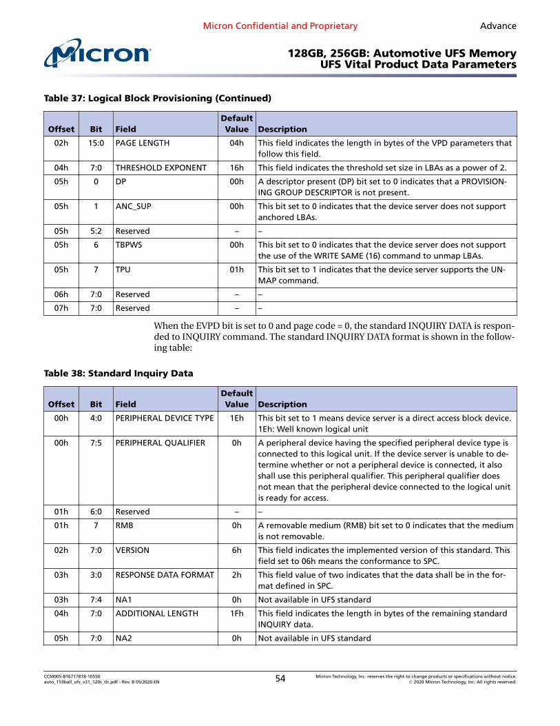
UFS Vital Product Data ParametersThe vital product data (VPD) pages are returned by an INQUIRY command with theEVPD bit set to 1, and contain vendor-specific product information about a logical unitand SCSI target device. A UFS device supports the following VPD pages.
Table 31: Supported VPD Pages
Offset Bit FieldDefaultValue Description
00h 4:0 PERIPHERAL DEVICE TYPE 1Eh This bit set to 1 means device server is a direct access block device.1Eh: Well-known logical unit
00h 7:5 PERIPHERAL QUALIFIER 0h A peripheral device having the specified peripheral device type isconnected to this logical unit. If the device server is unable to de-termine whether or not a peripheral device is connected, it alsoshall use this peripheral qualifier. This peripheral qualifier doesnot mean that the peripheral device connected to the logical unitis ready for access.
01h 7:0 PAGE CODE 0h This field identifies the VPD page and contains the same value asin this field in the INQUIRY CDB.
02h 15:0 PAGE LENGTH 08h This field indicates the length in bytes of the VPD parameters thatfollow this field.
04h 7:0 Supported VPD PageList[0]
0h The supported VPD page list contains a list of all VPD page codesimplemented by the logical unit in ascending order beginningwith page code 00h:SUPPORTED_VPD_PAGE
05h 7:0 Supported VPD PageList[1]
80h UNIT_SERIAL_NUM
06h 7:0 Supported VPD PageList[2]
83h DEVICE_ID
07h 7:0 Supported VPD PageList[3]
86h EXTENDED INQUIRY VPD
08h 7:0 Supported VPD PageList[4]
87h MODE_PAGE_POLICY
09h 7:0 Supported VPD PageList[5]
B0h BLOCK_LIMITS
0Ah 7:0 Supported VPD PageList[6]
B1h BLOCK_DEVICE_CHARACTERISTICS
0Bh 7:0 Supported VPD PageList[7]
B2h LOGICAL_BLOCK_PROVISIONING
Table 32: Unit Serial Number VPD Page
Offset Bit FieldDefaultValue Description
00h 4:0 PERIPHERAL DEVICE TYPE 1Eh This bit set to 1 means device server is a direct access block device.1Eh: Well-known logical unit
Micron Confidential and Proprietary Advance
128GB, 256GB: Automotive UFS MemoryUFS Vital Product Data Parameters
CCM005-816717818-10550auto_153ball_ufs_v31_120s_tlc.pdf - Rev. B 05/2020 EN 48 Micron Technology, Inc. reserves the right to change products or specifications without notice.
00h 7:5 PERIPHERAL QUALIFIER 0h A peripheral device having the specified peripheral device type isconnected to this logical unit. If the device server is unable to de-termine whether or not a peripheral device is connected, it alsoshall use this peripheral qualifier. This peripheral qualifier doesnot mean that the peripheral device connected to the logical unitis ready for access.
01h 7:0 PAGE CODE 80h This field identifies the VPD page and contains the same value asin this field in the INQUIRY CDB.
02h 15:0 PAGE LENGTH 4h This field indicates the length in bytes of the VPD parameters thatfollow this field.
04h 7:0 PRODUCT SERIAL NUM-BER
– This field contains right-aligned ASCII data that is vendor-assignedserial number.
Table 33: Device Identification VPD Page
Offset Bit FieldDefaultValue Description
00h 4:0 PERIPHERAL DEVICE TYPE 1Eh This bit set to 1 means device server is a direct access block device.1Eh: Well-known logical unit
00h 7:5 PERIPHERAL QUALIFIER 0h A peripheral device having the specified peripheral device type isconnected to this logical unit. If the device server is unable to de-termine whether or not a peripheral device is connected, it alsoshall use this peripheral qualifier. This peripheral qualifier doesnot mean that the peripheral device connected to the logical unitis ready for access.
01h 7:0 PAGE CODE 83h This field identifies the VPD page and contains the same value asin this field in the INQUIRY CDB.
02h 15:0 PAGE LENGTH Ch This field indicates the length in bytes of the VPD parameters thatfollow this field.
04h 4:0 CODE SET 2h This field contains a code set enumeration that indicates the for-mat of the DESIGNATOR field.
04h 7:5 PROTOCOL IDENTIFIER 0h This field may indicate the SCSI transport protocol to which thedesignation descriptor applies.
05h 3:0 DESIGNATOR TYPE 1h This field indicates the format and assignment authority for thedesignator.
05h 5:4 ASSOCIATION 0h This field indicates the entity with which the DESIGNATOR field isassociated. If a logical unit returns a designation descriptor withthis field set to 00b or 10b, it shall return the same descriptorwhen it is accessed through any other I_T nexus.
05h 6 Reserved – –
05h 7 PIV 0h A protocol identifier valid (PIV) bit set to 0 indicates the PROTO-COL IDENTIFIER field contents are reserved.
Micron Confidential and Proprietary Advance
128GB, 256GB: Automotive UFS MemoryUFS Vital Product Data Parameters
CCM005-816717818-10550auto_153ball_ufs_v31_120s_tlc.pdf - Rev. B 05/2020 EN 49 Micron Technology, Inc. reserves the right to change products or specifications without notice.
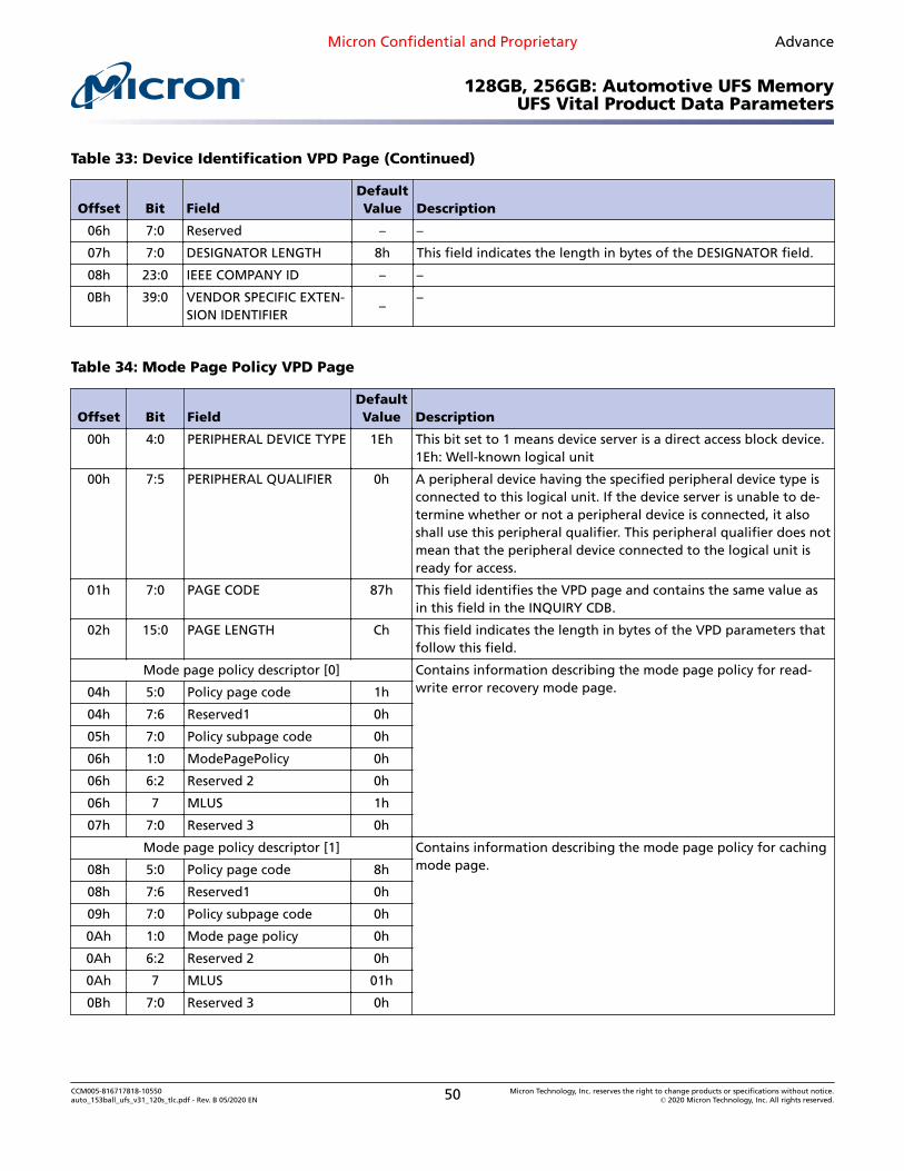
07h 7:0 DESIGNATOR LENGTH 8h This field indicates the length in bytes of the DESIGNATOR field.
08h 23:0 IEEE COMPANY ID – –
0Bh 39:0 VENDOR SPECIFIC EXTEN-SION IDENTIFIER
––
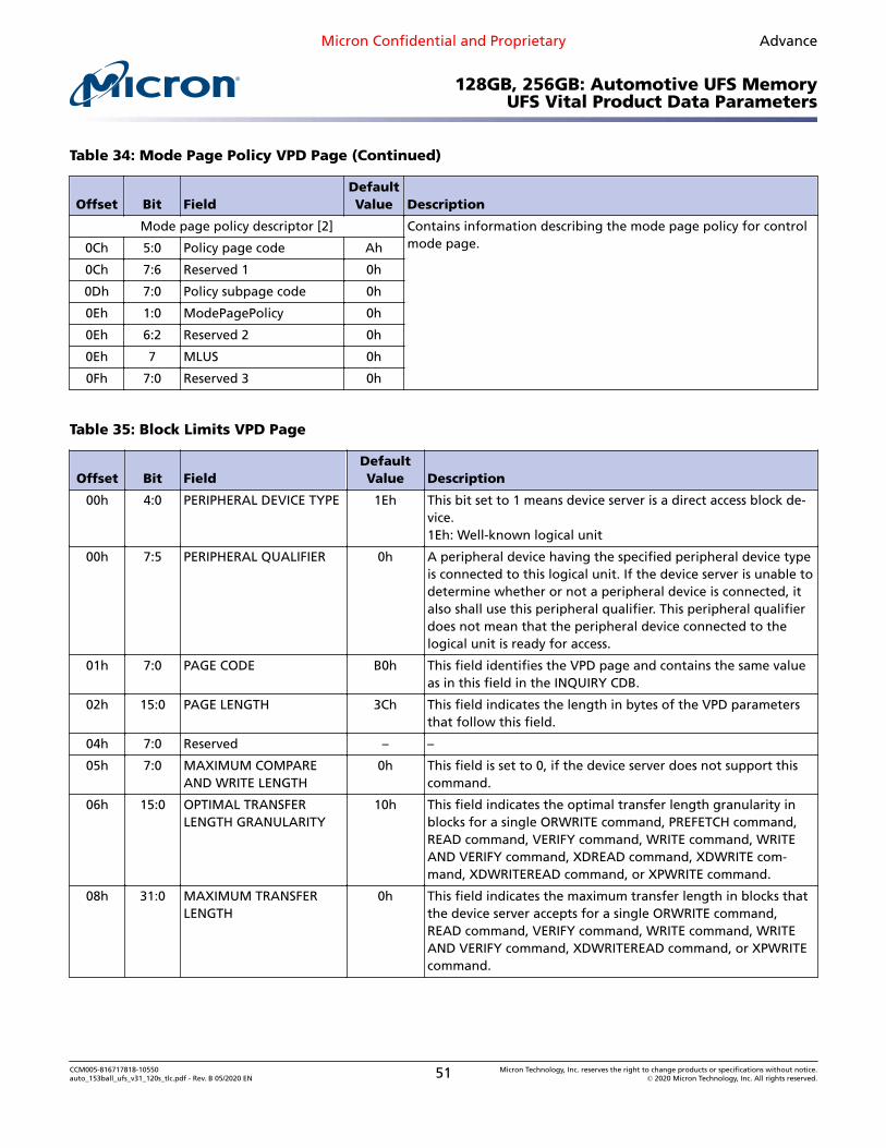
Table 34: Mode Page Policy VPD Page
Offset Bit FieldDefaultValue Description
00h 4:0 PERIPHERAL DEVICE TYPE 1Eh This bit set to 1 means device server is a direct access block device.1Eh: Well-known logical unit
00h 7:5 PERIPHERAL QUALIFIER 0h A peripheral device having the specified peripheral device type isconnected to this logical unit. If the device server is unable to de-termine whether or not a peripheral device is connected, it alsoshall use this peripheral qualifier. This peripheral qualifier does notmean that the peripheral device connected to the logical unit isready for access.
01h 7:0 PAGE CODE 87h This field identifies the VPD page and contains the same value asin this field in the INQUIRY CDB.
02h 15:0 PAGE LENGTH Ch This field indicates the length in bytes of the VPD parameters thatfollow this field.
Mode page policy descriptor [0] Contains information describing the mode page policy for read-write error recovery mode page.04h 5:0 Policy page code 1h
04h 7:6 Reserved1 0h
05h 7:0 Policy subpage code 0h
06h 1:0 ModePagePolicy 0h
06h 6:2 Reserved 2 0h
06h 7 MLUS 1h
07h 7:0 Reserved 3 0h
Mode page policy descriptor [1] Contains information describing the mode page policy for cachingmode page.08h 5:0 Policy page code 8h
08h 7:6 Reserved1 0h
09h 7:0 Policy subpage code 0h
0Ah 1:0 Mode page policy 0h
0Ah 6:2 Reserved 2 0h
0Ah 7 MLUS 01h
0Bh 7:0 Reserved 3 0h
Micron Confidential and Proprietary Advance
128GB, 256GB: Automotive UFS MemoryUFS Vital Product Data Parameters
CCM005-816717818-10550auto_153ball_ufs_v31_120s_tlc.pdf - Rev. B 05/2020 EN 50 Micron Technology, Inc. reserves the right to change products or specifications without notice.
Mode page policy descriptor [2] Contains information describing the mode page policy for controlmode page.0Ch 5:0 Policy page code Ah
0Ch 7:6 Reserved 1 0h
0Dh 7:0 Policy subpage code 0h
0Eh 1:0 ModePagePolicy 0h
0Eh 6:2 Reserved 2 0h
0Eh 7 MLUS 0h
0Fh 7:0 Reserved 3 0h
Table 35: Block Limits VPD Page
Offset Bit FieldDefaultValue Description
00h 4:0 PERIPHERAL DEVICE TYPE 1Eh This bit set to 1 means device server is a direct access block de-vice.1Eh: Well-known logical unit
00h 7:5 PERIPHERAL QUALIFIER 0h A peripheral device having the specified peripheral device typeis connected to this logical unit. If the device server is unable todetermine whether or not a peripheral device is connected, italso shall use this peripheral qualifier. This peripheral qualifierdoes not mean that the peripheral device connected to thelogical unit is ready for access.
01h 7:0 PAGE CODE B0h This field identifies the VPD page and contains the same valueas in this field in the INQUIRY CDB.
02h 15:0 PAGE LENGTH 3Ch This field indicates the length in bytes of the VPD parametersthat follow this field.
04h 7:0 Reserved – –
05h 7:0 MAXIMUM COMPAREAND WRITE LENGTH
0h This field is set to 0, if the device server does not support thiscommand.
06h 15:0 OPTIMAL TRANSFERLENGTH GRANULARITY
10h This field indicates the optimal transfer length granularity inblocks for a single ORWRITE command, PREFETCH command,READ command, VERIFY command, WRITE command, WRITEAND VERIFY command, XDREAD command, XDWRITE com-mand, XDWRITEREAD command, or XPWRITE command.
08h 31:0 MAXIMUM TRANSFERLENGTH
0h This field indicates the maximum transfer length in blocks thatthe device server accepts for a single ORWRITE command,READ command, VERIFY command, WRITE command, WRITEAND VERIFY command, XDWRITEREAD command, or XPWRITEcommand.
Micron Confidential and Proprietary Advance
128GB, 256GB: Automotive UFS MemoryUFS Vital Product Data Parameters
CCM005-816717818-10550auto_153ball_ufs_v31_120s_tlc.pdf - Rev. B 05/2020 EN 51 Micron Technology, Inc. reserves the right to change products or specifications without notice.
10h This field indicates the optimal transfer length in blocks for asingle ORWRITE command, PREFETCH command, READ com-mand, VERIFY command, WRITE command, WRITE AND VERIFYcommand, XDREAD command, XDWRITE command, XDWRITE-READ command, or XPWRITE command.
10h 31:0 MAXIMUM PREFETCHXDREAD XDWRITETRANSFER LENGTH
100h This field indicates:a) the maximum transfer length in blocks that the device serveraccepts for a single PREFETCH commandb) if the XOR control mode page is implemented, then themaximum value supported by the MAXIMUM XOR WRITE SIZEfield in the XOR control mode page.c) if the XOR control mode page is not implemented, then themaximum transfer length in blocks that the device server ac-cepts for a single XDWRITE command or XDREAD command.The device server should set this field to less than or equal tothe MAXIMUM TRANSFER LENGTH field.
14h 31:0 MAXIMUM UNMAP LBACOUNT
FFFFFFFFh This field indicates the maximum number of LBAs that may beunmapped by an UNMAP command.If the number of LBAs that may be unmapped by an UNMAPcommand is constrained only by the amount of data that maybe contained in the UNMAP parameter list, then the deviceserver shall set this field to FFFF_FFFFh.If the device server implements the UNMAP command, thenthe value in this field shall be greater than or equal to 1.
18h 31:0 MAXIMUM UNMAPBLOCK DESCRIPTORCOUNT
10h This field indicates the maximum number of unmap block de-scriptors that shall be contained in the parameter data trans-ferred to the device server for an UNMAP command.If there is no limit on the number of unmap block descriptorscontained in the parameter data, then the device server shallset this field to FFFF_FFFFh.If the device server implements the UNMAP command, thenthe value in this field shall be greater than or equal to 1.
1Ch 31:0 OPTIMAL UNMAP GRAN-ULARITY
1h This field indicates the optimal granularity in logical blocks forunmap requests. An unmap request with a number of logicalblocks that is not a multiple of this value may result in UNMAPoperations on fewer LBAs than requested.If this field is set to 0000_0000h, then the optimal unmap gran-ularity is not specified.
20h 30:0 UNMAP GRANULARITYALIGNMENT
0h This field indicates the LBA of the first logical block to whichthe OPTIMAL UNMAP GRANULARITY field applies.The unmap granularity alignment is used to calculate an opti-mal unmap request starting LBA as follows:Optimal unmap request starting LBA = (n × OPTIMAL UNMAPGRANULARITY) + UNMAP GRANULARITY ALIGNMENTWhere n is 0 or any positive integer value.
Micron Confidential and Proprietary Advance
128GB, 256GB: Automotive UFS MemoryUFS Vital Product Data Parameters
CCM005-816717818-10550auto_153ball_ufs_v31_120s_tlc.pdf - Rev. B 05/2020 EN 52 Micron Technology, Inc. reserves the right to change products or specifications without notice.
20h 31 UGAVALID 0h An unmap granularity alignment valid (UGAVALID) bit set to 0indicates that the UNMAP GRANULARITY ALIGNMENT field isnot valid.
Table 36: Block Device Characteristics
Offset Bit FieldDefaultValue Description
00h 4:0 PERIPHERAL DEVICE TYPE 1Eh This bit set to 1 means device server is a direct access block device.1Eh: Well-known logical unit
00h 7:5 PERIPHERAL QUALIFIER 000h A peripheral device having the specified peripheral device type isconnected to this logical unit. If the device server is unable to de-termine whether or not a peripheral device is connected, it alsoshall use this peripheral qualifier. This peripheral qualifier doesnot mean that the peripheral device connected to the logical unitis ready for access.
01h 7:0 PAGE CODE B1h This fields identifies the VPD page and contains the same value asin the PAGE CODE field in the INQUIRY CDB.
02h 15:0 PAGE LENGTH 3Ch This field indicates the length in bytes of the VPD parameters thatfollow this field.
04h 15:0 MEDIUM ROTATION RATE 0001h 0001h means device is a non-rotating medium (for example, solidstate).
06h 7:0 Reserved – –
07h 3:0 NOMINAL FORM FACTOR 05h This field indicates the nominal form factor of the device contain-ing the logical unit.
07h 7:4 Reserved – –
Table 37: Logical Block Provisioning
Offset Bit FieldDefaultValue Description
00h 4:0 PERIPHERAL DEVICE TYPE 1Eh This bit set to 1 means device server is a direct access block device.1Eh: Well known logical unit
00h 7:5 PERIPHERAL QUALIFIER 000h A peripheral device having the specified peripheral device type isconnected to this logical unit. If the device server is unable to de-termine whether or not a peripheral device is connected, it alsoshall use this peripheral qualifier. This peripheral qualifier doesnot mean that the peripheral device connected to the logical unitis ready for access.
01h 7:0 PAGE CODE B2h This fields identifies the VPD page and contains the same value asin the PAGE CODE field in the INQUIRY CDB.
Micron Confidential and Proprietary Advance
128GB, 256GB: Automotive UFS MemoryUFS Vital Product Data Parameters
CCM005-816717818-10550auto_153ball_ufs_v31_120s_tlc.pdf - Rev. B 05/2020 EN 53 Micron Technology, Inc. reserves the right to change products or specifications without notice.
02h 15:0 PAGE LENGTH 04h This field indicates the length in bytes of the VPD parameters thatfollow this field.
04h 7:0 THRESHOLD EXPONENT 16h This field indicates the threshold set size in LBAs as a power of 2.
05h 0 DP 00h A descriptor present (DP) bit set to 0 indicates that a PROVISION-ING GROUP DESCRIPTOR is not present.
05h 1 ANC_SUP 00h This bit set to 0 indicates that the device server does not supportanchored LBAs.
05h 5:2 Reserved – –
05h 6 TBPWS 00h This bit set to 0 indicates that the device server does not supportthe use of the WRITE SAME (16) command to unmap LBAs.
05h 7 TPU 01h This bit set to 1 indicates that the device server supports the UN-MAP command.
06h 7:0 Reserved – –
07h 7:0 Reserved – –
When the EVPD bit is set to 0 and page code = 0, the standard INQUIRY DATA is respon-ded to INQUIRY command. The standard INQUIRY DATA format is shown in the follow-ing table:
Table 38: Standard Inquiry Data
Offset Bit FieldDefaultValue Description
00h 4:0 PERIPHERAL DEVICE TYPE 1Eh This bit set to 1 means device server is a direct access block device.1Eh: Well known logical unit
00h 7:5 PERIPHERAL QUALIFIER 0h A peripheral device having the specified peripheral device type isconnected to this logical unit. If the device server is unable to de-termine whether or not a peripheral device is connected, it alsoshall use this peripheral qualifier. This peripheral qualifier doesnot mean that the peripheral device connected to the logical unitis ready for access.
01h 6:0 Reserved – –
01h 7 RMB 0h A removable medium (RMB) bit set to 0 indicates that the mediumis not removable.
02h 7:0 VERSION 6h This field indicates the implemented version of this standard. Thisfield set to 06h means the conformance to SPC.
03h 3:0 RESPONSE DATA FORMAT 2h This field value of two indicates that the data shall be in the for-mat defined in SPC.
03h 7:4 NA1 0h Not available in UFS standard
04h 7:0 ADDITIONAL LENGTH 1Fh This field indicates the length in bytes of the remaining standardINQUIRY data.
05h 7:0 NA2 0h Not available in UFS standard
Micron Confidential and Proprietary Advance
128GB, 256GB: Automotive UFS MemoryUFS Vital Product Data Parameters
CCM005-816717818-10550auto_153ball_ufs_v31_120s_tlc.pdf - Rev. B 05/2020 EN 54 Micron Technology, Inc. reserves the right to change products or specifications without notice.
07h 1 CMDQUE 1h This bit is set to 1 indicating that the logical unit supports thecommand management model (SAM).
07h 7:2 NA5 0h Not available in UFS standard
08h 15:0 VENDOR IDENTIFICATION–
This field contains left-aligned ASCII data identifying the vendorof the product.
10h 15:0 PRODUCT IDENTIFICA-TION
–This field contains left-aligned ASCII data defined by the vendor.
20h 15:0 PRODUCT REVISION LEV-EL
–This field contains left-aligned ASCII data defined by the vendor.
The extended INQUIRY DATA format is shown in the following table:
Table 39: Extended Inquiry Data
Offset Bit FieldDefaultValue Description
00h 4:0 PERIPHERAL DEVICE TYPE 1Eh This bit set to 1 means device server is a direct access block device.1Eh: Well-known logical unit
00h 7:5 PERIPHERAL QUALIFIER 0h A peripheral device having the specified peripheral device type isconnected to this logical unit. If the device server is unable to de-termine whether or not a peripheral device is connected, it alsoshall use this peripheral qualifier. This peripheral qualifier doesnot mean that the peripheral device connected to the logical unitis ready for access.
01h 7:0 PAGE CODE 86h This field identifies the VPD page.
02h 15:0 PAGE LENGTH 3Ch The PAGE LENGTH field specifies the length of the VPD page data.
04h 7:6 ACTIVATE MICROCODE B0h This field indicates how a device server activates microcode andestablishes a unit attention condition when a WRITE BUFFER com-mand with the download microcode mode set to 05h or 07h isprocessed.
04h 5:0 Reserved - -
05h 7:6 Reserved - -
05h 5:0 FEATURES SUPPORT 37h These fields indicate if some specific functions are supported bythe device.
06h 7:1 Reserved - -
06h 0 V_SUP 1h This bit is set to 1 when the device server supports a volatile cacheand the applicable command standard defines features using thiscache.
07h 7:5 Reserved - -
Micron Confidential and Proprietary Advance
128GB, 256GB: Automotive UFS MemoryUFS Vital Product Data Parameters
CCM005-816717818-10550auto_153ball_ufs_v31_120s_tlc.pdf - Rev. B 05/2020 EN 55 Micron Technology, Inc. reserves the right to change products or specifications without notice.
07h 4 P_I_I_SUP 0h This bit is set to 0, indicating that the logical unit does not supportprotection information intervals.
07h 3:0 Reserved - -
08h 7:5 Reserved – -
08h 4 R_SUP0h
This bit is set to 0, indicating that the device server does not sup-port referrals.
08h 3:0 Reserved - -
09h 7:4 Reserved - -
09h 3:0 MULTI I_T NEXUS MICRO-CODE DOWNLOAD 5h
This field indicates how the device server handles concurrent at-tempts to download microcode using the WRITE BUFFER com-mand from multiple I_T nexuses.
10h 15:0 EXTENDED SELF_TESTCOMPLETION MINUTES
0hA value of 0h indicates that the EXTENDED SELF-TEST COMPLE-TION MINUTES field is not supported.
12h 7:0 Reserved – -
Micron Confidential and Proprietary Advance
128GB, 256GB: Automotive UFS MemoryUFS Vital Product Data Parameters
CCM005-816717818-10550auto_153ball_ufs_v31_120s_tlc.pdf - Rev. B 05/2020 EN 56 Micron Technology, Inc. reserves the right to change products or specifications without notice.
Electrical SpecificationsAccording to JEDEC UFS v3.1 specification, power-up timing starts when the supplyvoltage crosses 300mV and ends when it reaches the minimum operating value. Microndevice only supports VCC and VCCQ. VCCQ2 is not used.
CCM005-816717818-10550auto_153ball_ufs_v31_120s_tlc.pdf - Rev. B 05/2020 EN 57 Micron Technology, Inc. reserves the right to change products or specifications without notice.
• Removed 512GB• Updated UFS Performance section• Updated PHY M-RX Capability Attributes• Updated Descriptors• Added Extended Inquiry Data• Updated Features section• Updated current consumption• Updated notes in Package Dimensions section
Rev. A – 03/2020
• Initial release
8000 S. Federal Way, P.O. Box 6, Boise, ID 83707-0006, Tel: 208-368-4000www.micron.com/products/support Sales inquiries: 800-932-4992
Micron and the Micron logo are trademarks of Micron Technology, Inc.All other trademarks are the property of their respective owners.
This data sheet contains initial descriptions of products still under development.
Micron Confidential and Proprietary Advance
128GB, 256GB: Automotive UFS MemoryRevision History
CCM005-816717818-10550auto_153ball_ufs_v31_120s_tlc.pdf - Rev. B 05/2020 EN 58 Micron Technology, Inc. reserves the right to change products or specifications without notice.