INSTRUCTION MANUAL • For any further information please contact your local dealer or call: For spare parts drawings refer to the section “ LIST OF COMPONENTS” enclosed to this manual. GB TRANSLATION FROM THE ORI- GINAL INSTRUCTIONS 1296-M101-1_R 1296-M101-1_R Technical services: RAVAGLIOLI S.p.A. - Via 1° Maggio, 3 - 40037 Pontecchio Marconi - Bologna Italy Phone (+39) 051 6781511 - Telex 510697 RAV I - Fax (+39) 051 846349 - e-mail: [email protected]G2.116HD - G2.117HD G2.118HD - G2.119HD G2.119HMD - G2.119HFMD G2.120HD - G2.121HD G2.124HD - GP2.124HD - Rev. n. 1 (03/2014)
Transcript
INSTRUCTION MANUAL
• For any further information please contact your local dealer or call:
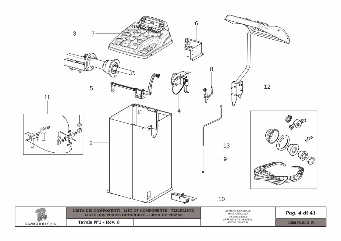
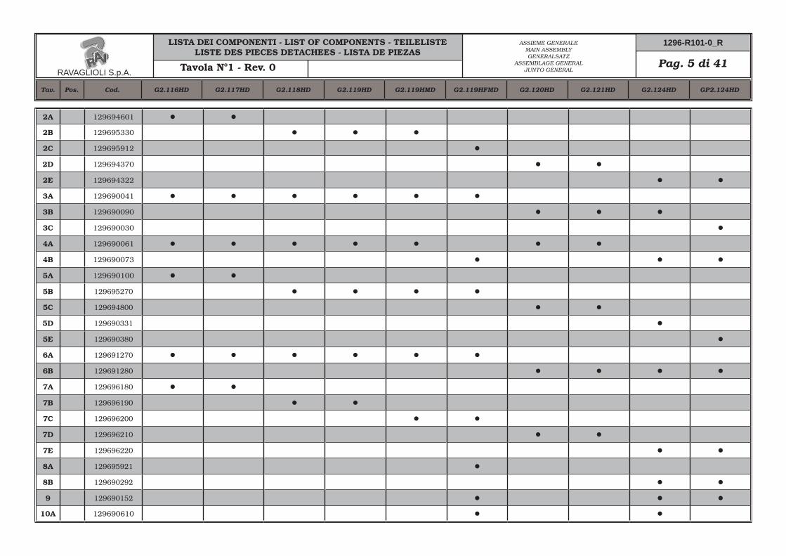
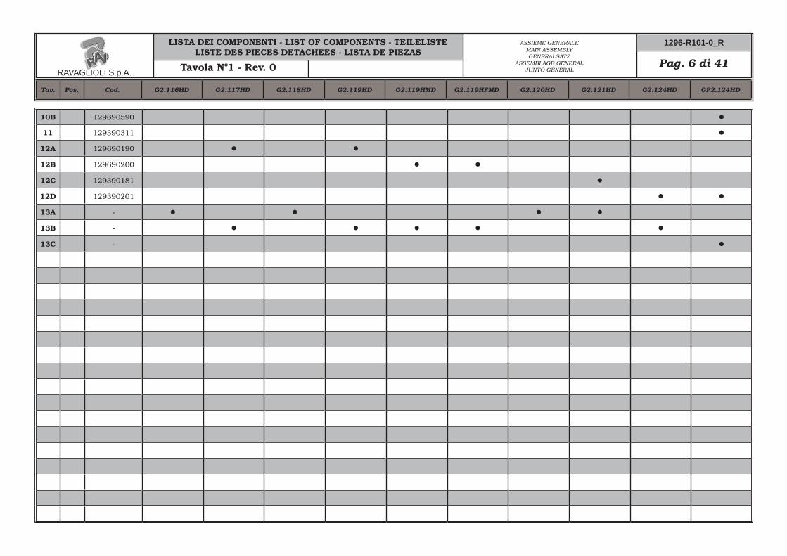
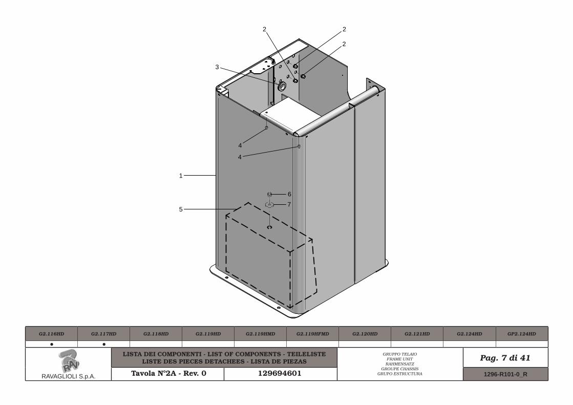
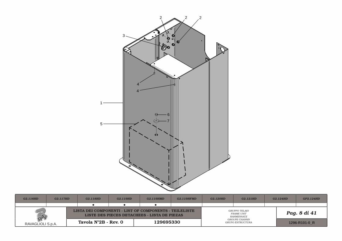
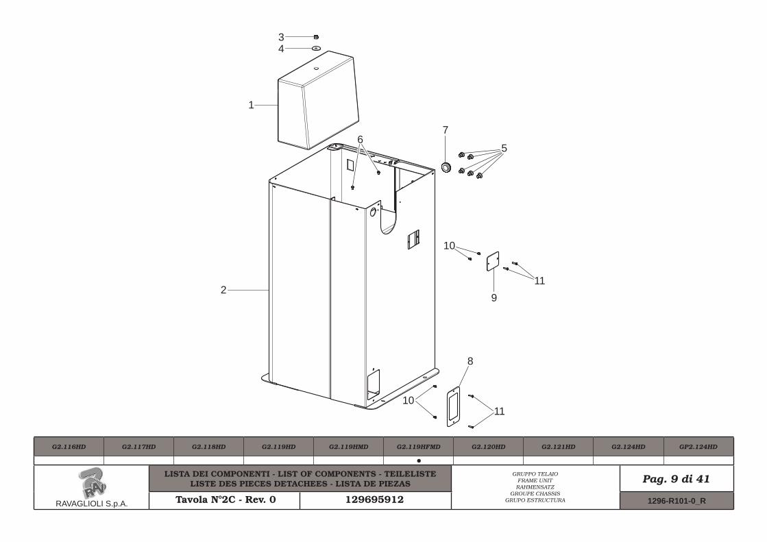
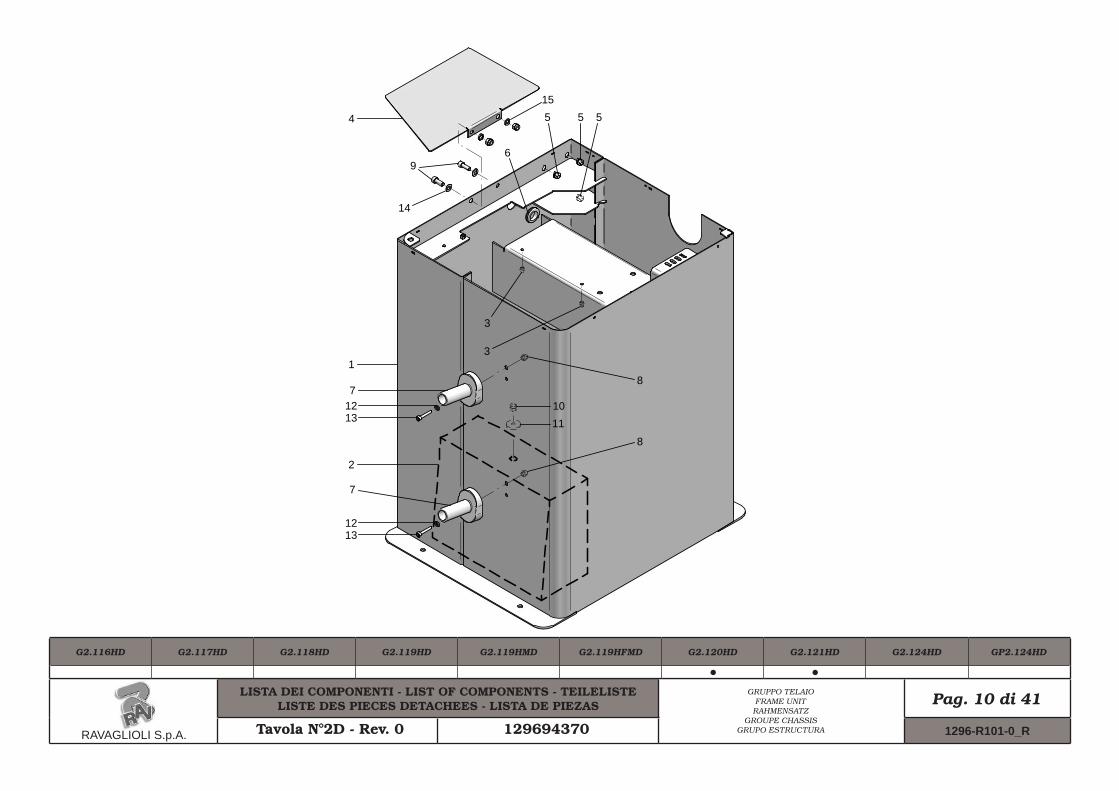
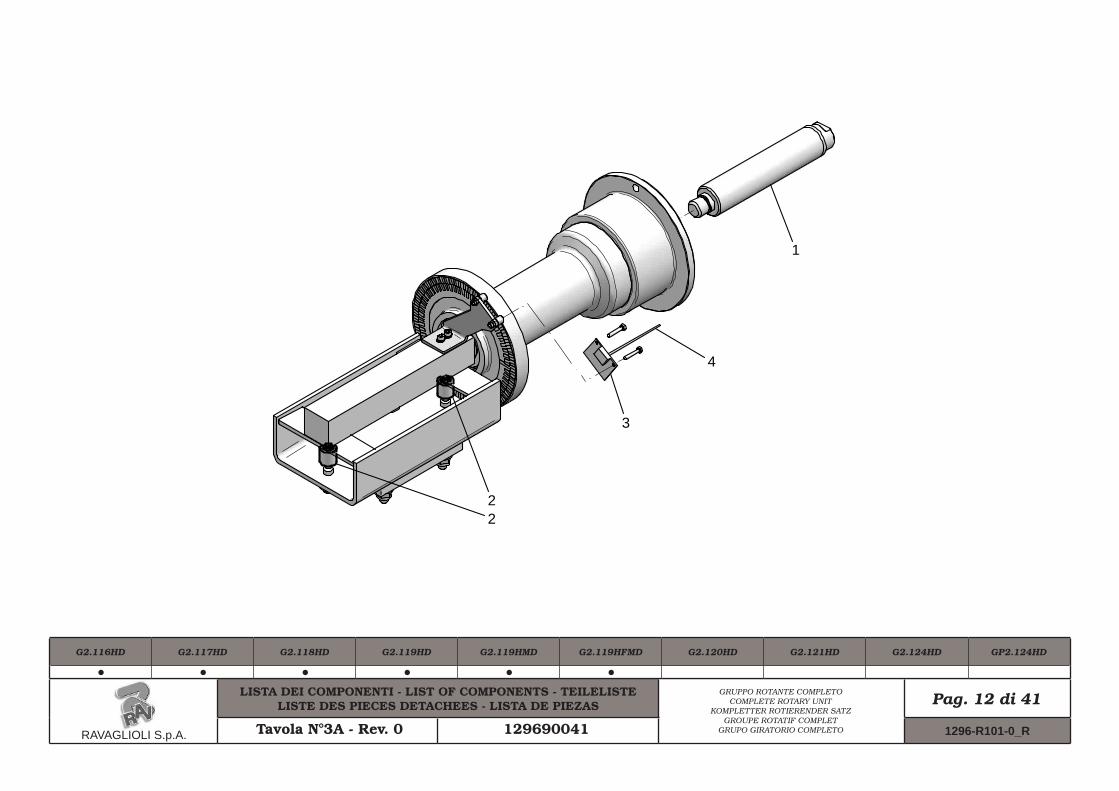
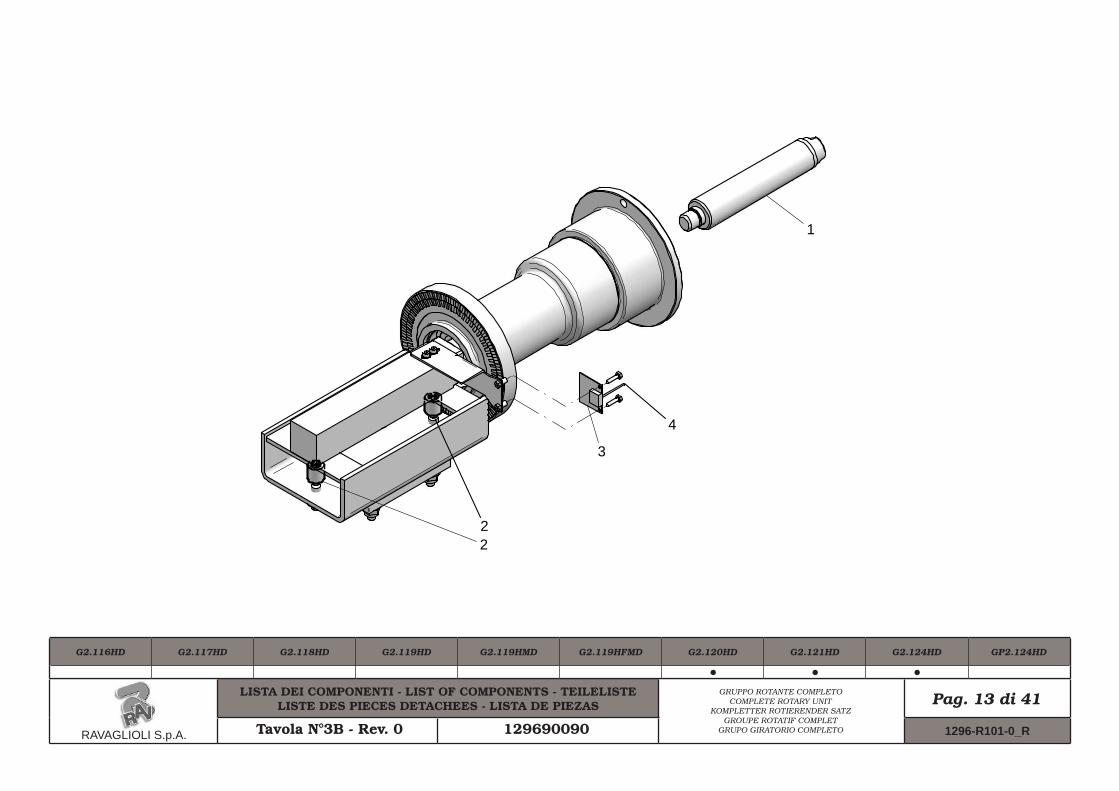
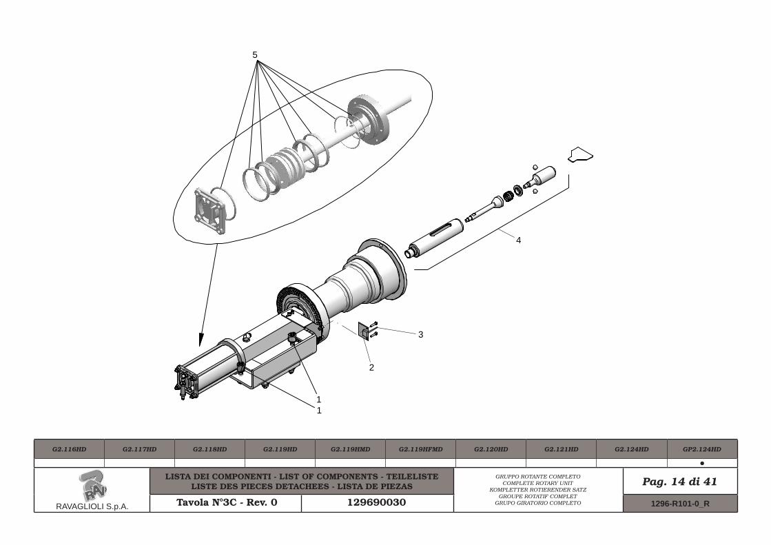
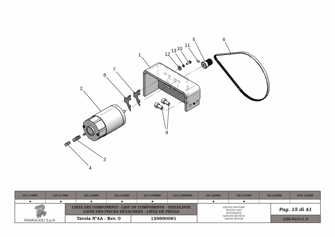
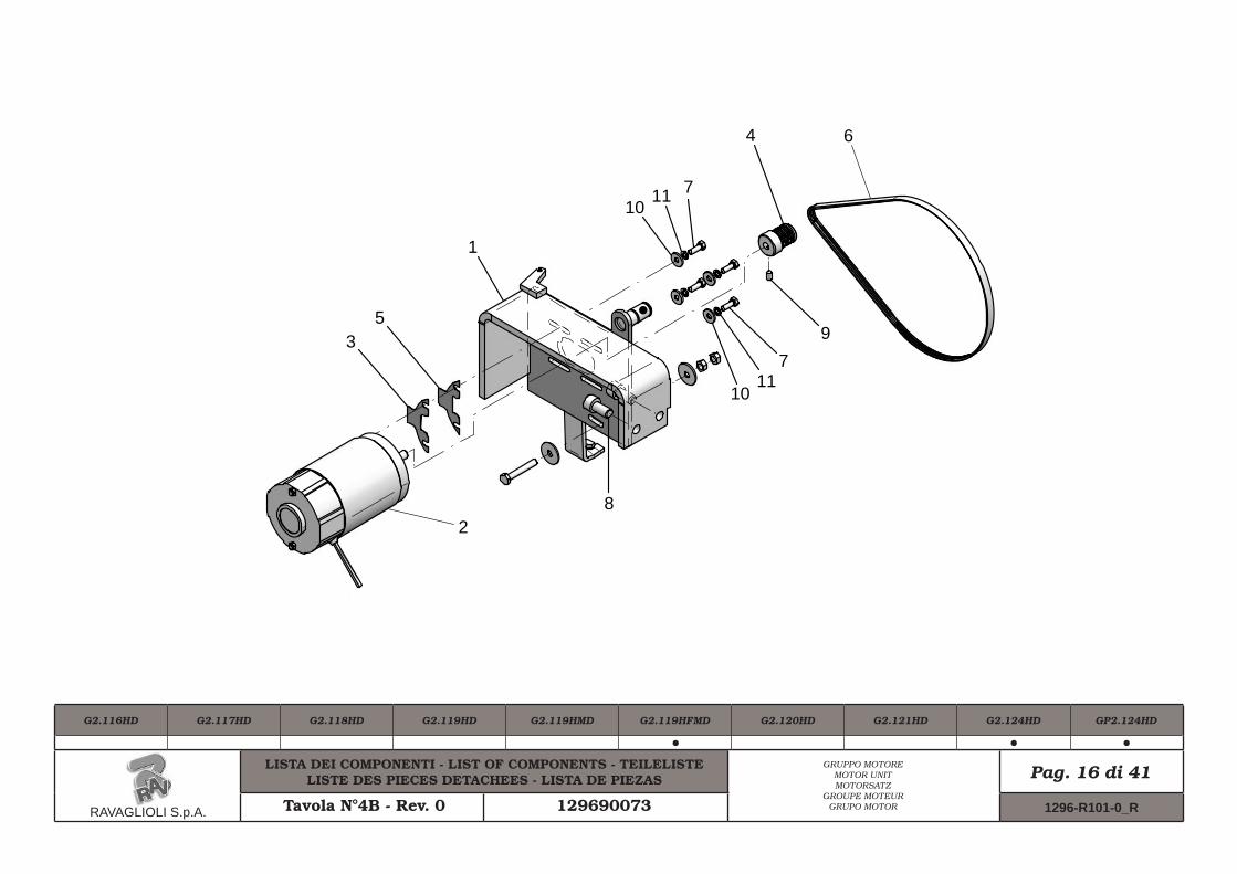
For spare parts drawings refer to the section “ LIST OF COMPONENTS” enclosed to this manual.
INSTRUCTION, USE AND MAINTENANCE MANUALGB Page 7 of 54
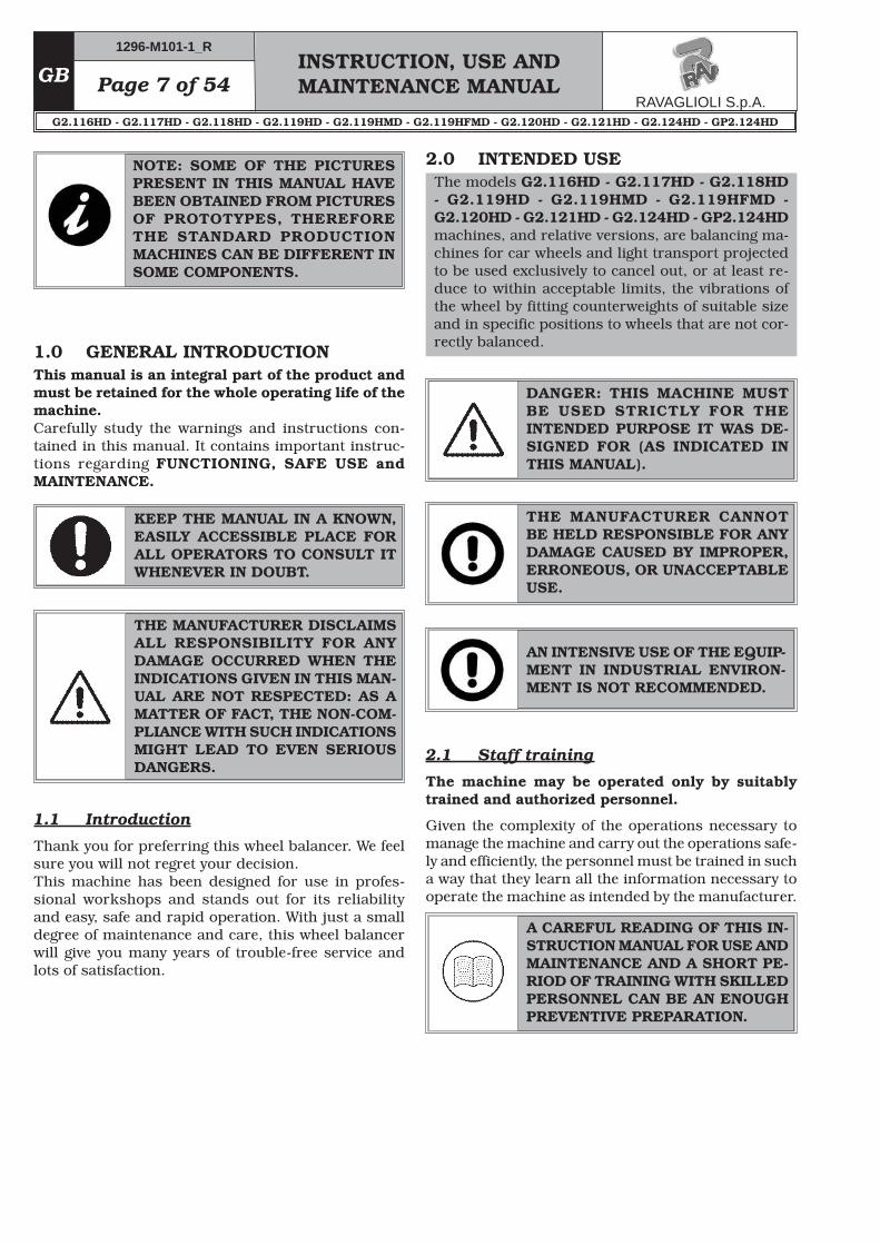
1.0 GENERAL INTRODUCTIONThis manual is an integral part of the product and must be retained for the whole operating life of the machine.Carefully study the warnings and instructions con-tained in this manual. It contains important instruc-tions regarding FUNCTIONING, SAFE USE and MAINTENANCE.
KEEP THE MANUAL IN A KNOWN, EASILY ACCESSIBLE PLACE FOR ALL OPERATORS TO CONSULT IT WHENEVER IN DOUBT.
THE MANUFACTURER DISCLAIMS ALL RESPONSIBILITY FOR ANY DAMAGE OCCURRED WHEN THE INDICATIONS GIVEN IN THIS MAN-UAL ARE NOT RESPECTED: AS A MATTER OF FACT, THE NON-COM-PLIANCE WITH SUCH INDICATIONS MIGHT LEAD TO EVEN SERIOUS DANGERS.
1.1 Introduction
Thank you for preferring this wheel balancer. We feel sure you will not regret your decision.This machine has been designed for use in profes-sional workshops and stands out for its reliability and easy, safe and rapid operation. With just a small degree of maintenance and care, this wheel balancer will give you many years of trouble-free service and lots of satisfaction.
DANGER: THIS MACHINE MUST BE USED STRICTLY FOR THE INTENDED PURPOSE IT WAS DE-SIGNED FOR (AS INDICATED IN THIS MANUAL).
2.1 Staff training
The machine may be operated only by suitably trained and authorized personnel.
Given the complexity of the operations necessary to manage the machine and carry out the operations safe-ly and efficiently, the personnel must be trained in such a way that they learn all the information necessary to operate the machine as intended by the manufacturer.
A CAREFUL READING OF THIS IN-STRUCTION MANUAL FOR USE AND MAINTENANCE AND A SHORT PE-RIOD OF TRAINING WITH SKILLED PERSONNEL CAN BE AN ENOUGH PREVENTIVE PREPARATION.
THE MANUFACTURER CANNOT BE HELD RESPONSIBLE FOR ANY DAMAGE CAUSED BY IMPROPER, ERRONEOUS, OR UNACCEPTABLE USE.
AN INTENSIVE USE OF THE EQUIP-MENT IN INDUSTRIAL ENVIRON-MENT IS NOT RECOMMENDED.
NOTE: SOME OF THE PICTURES PRESENT IN THIS MANUAL HAVE BEEN OBTAINED FROM PICTURES OF PROTOTYPES, THEREFORE THE STANDARD PRODUCTION MACHINES CAN BE DIFFERENT IN SOME COMPONENTS.
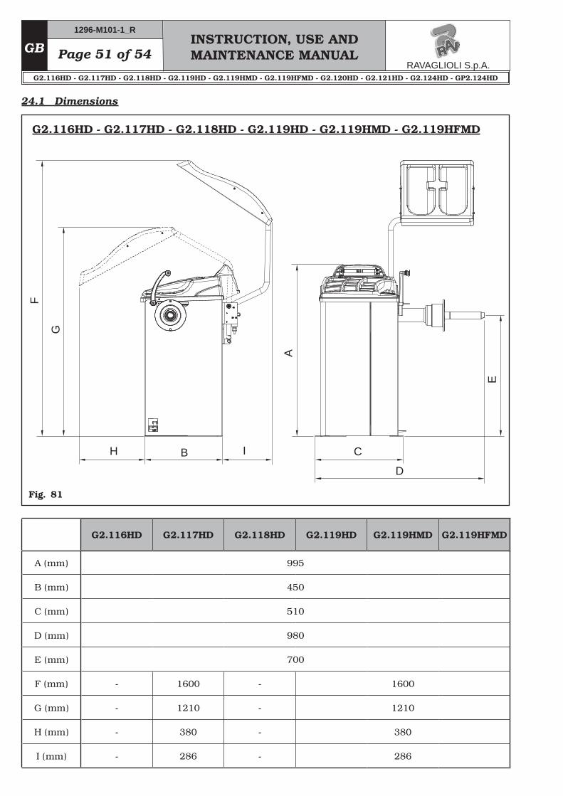
2.0 INTENDED USEThe models G2.116HD - G2.117HD - G2.118HD - G2.119HD - G2.119HMD - G2.119HFMD - G2.120HD - G2.121HD - G2.124HD - GP2.124HD machines, and relative versions, are balancing ma-chines for car wheels and light transport projected to be used exclusively to cancel out, or at least re-duce to within acceptable limits, the vibrations of the wheel by fitting counterweights of suitable size and in specific positions to wheels that are not cor-rectly balanced.
Page 8 of 54INSTRUCTION, USE AND MAINTENANCE MANUAL
GB
THE MANUFACTURER DENIES ANY RESPONSIBILITY IN CASE OF DAMAGES CAUSED BY UNAU-THORIZED MODIFICATIONS OR BY THE USE OF NON ORIGINAL COMPONENTS OR EQUIPMENT.
• Installation must be conducted only by qualified personnel exactly according to the instructions that are given below.
• Ensure that there are no dangerous situations dur-ing the machine operating manoeuvres. Immediately stop the machine if it miss-functions and contact the assistance service of an authorized dealer.
• In emergency situations and before carrying out any maintenance or repairs, disconnect all supplies to the machine by using the main switch, placed on the machine itself, and unplugging the power supply.
• The machine electrical supply system must be equipped with an appropriate earthing, to which the yellow-green machine protection wire must be connected.
• Ensure that the work area around the machine is free of potentially dangerous objects and that there is no oil since this could damage the tyres. Oil on the floor is also a potential danger for the operator.
• UNDER NO CIRCUMSTANCES must the machine be used to spin anything but vehicle wheels. Bad locking can cause rotating parts to come loose, with potential damage to the machine and anything in the vicinity and injury to the operator.
4.0 GENERAL SAFETY RULES
• Any tampering with or modification to the machine not previously authorized by the manufacturer ex-empts the latter from all responsibility for damage caused by or derived from said actions.
• Removing of or tampering with the safety devices or with the warning signals placed on the machine leads to serious dangers and represents a transgression of European safety rules.
• Use of the machine is only permitted in places free from explosion or fire hazard and in dry places under cover.
• Original spare parts and accessories should be used.
Its function is to prevent the operator from danger-ous mistakes.
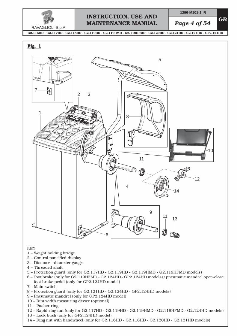
• Master switchIts function is to disconnect machine electric supply.
• Protection guard (only for G2.117HD - G2.119HD - G2.119HMD - G2.119HFMD - G2.121HD - G2.124HD - GP2.124HD models)Its function is to protect the operator from possible projections of materials on the wheel during its spin.Wheel spinning is normally prevented if the wheel protection guard is raised (open). When the protection guard is open, this interrupts the cir-cuit that triggers the motor and automatic start is prevented, including in the case of an error.
Press key on the keyboard to stop the wheel in emergency conditions.
3.1 Residual risks
The machine was subjected to a complete analysis of risks according to reference standard EN ISO 12100.Risks are as reduced as possible in relation with tech-nology and product functionality.Possible residual risks have been emphasized through pictorial representations and warnings which placing is indicated in “ PLATE POSITIONING TABLE” at page 6.
INSTRUCTION, USE AND MAINTENANCE MANUALGB Page 9 of 54
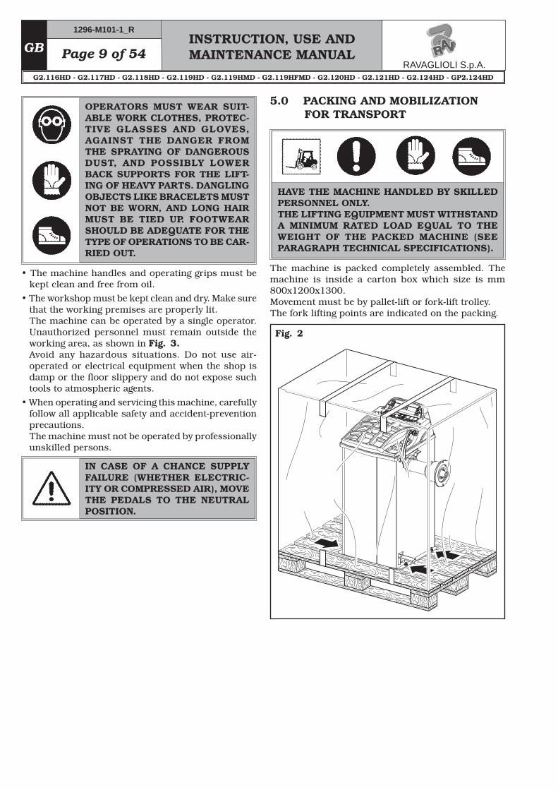
5.0 PACKING AND MOBILIZATION FOR TRANSPORT
Fig. 2
IN CASE OF A CHANCE SUPPLY FAILURE (WHETHER ELECTRIC-ITY OR COMPRESSED AIR), MOVE THE PEDALS TO THE NEUTRAL POSITION.
The machine is packed completely assembled. The machine is inside a carton box which size is mm 800x1200x1300.Movement must be by pallet-lift or fork-lift trolley. The fork lifting points are indicated on the packing.
HAVE THE MACHINE HANDLED BY SKILLED PERSONNEL ONLY. THE LIFTING EQUIPMENT MUST WITHSTAND A MINIMUM RATED LOAD EQUAL TO THE WEIGHT OF THE PACKED MACHINE (SEE PARAGRAPH TECHNICAL SPECIFICATIONS).
• The machine handles and operating grips must be kept clean and free from oil.
• The workshop must be kept clean and dry. Make sure that the working premises are properly lit.The machine can be operated by a single operator. Unauthorized personnel must remain outside the working area, as shown in Fig. 3.Avoid any hazardous situations. Do not use air-operated or electrical equipment when the shop is damp or the floor slippery and do not expose such tools to atmospheric agents.
• When operating and servicing this machine, carefully follow all applicable safety and accident-prevention precautions.The machine must not be operated by professionally unskilled persons.
OPERATORS MUST WEAR SUIT-ABLE WORK CLOTHES, PROTEC-TIVE GLASSES AND GLOVES, AGAINST THE DANGER FROM THE SPRAYING OF DANGEROUS DUST, AND POSSIBLY LOWER BACK SUPPORTS FOR THE LIFT-ING OF HEAVY PARTS. DANGLING OBJECTS LIKE BRACELETS MUST NOT BE WORN, AND LONG HAIR MUST BE TIED UP. FOOTWEAR SHOULD BE ADEQUATE FOR THE TYPE OF OPERATIONS TO BE CAR-RIED OUT.
Page 10 of 54INSTRUCTION, USE AND MAINTENANCE MANUAL
GB
7.0 MOBILIZATION6.0 UNPACKING
The cardboard box is supported with plastic strapping. Cut the strapping with suitable scissors. Use a small knife to cut along the lateral axis of the box and open it like a fan.It is also possible to unnail the cardboard box from the pallet it is fixed to. After removing the packing, and in the case of the machine packed fully assembled, check that the machine is complete and that there is no visible damage. If in doubt do not use the machine and refer to pro-fessionally qualified personnel (to the seller).The packing (plastic bags, expanded polystyrene, nails, screws, timber, etc.) should not be left within reach of children since it is potentially dangerous. These ma-terials should be deposited in the relevant collection points if they are pollutants or non biodegradable.
DURING UNPACKING, ALWAYS WEAR GLOVES TO PREVENT ANY INJURY CAUSED BY CONTACT WITH PACKAGING MATERIAL (NAILS, ETC.).
THE BOX CONTAINING THE FIX-TURES IS CONTAINED IN THE WRAPPING. DO NOT THROW IT AWAY WITH THE PACKING.
If the machine has to be moved from its normal work post, the movement must be conducted following the instructions listed below.• Protect the exposed corners with suitable material
(Pluribol/cardboard).• Do not use metallic cables for lifting.• Make sure that the electricity supply is not connected.• Place again the machine onto the original pallet with
whom it was delivered.• Use transpallet or fork-lift for handling.
8.0 WORKING ENVIRONMENT CONDI-TIONS
The machine must be operated under proper condi-tions as follows:• temperature: 0° + 45° C • relative humidity: 30 - 90% (dew-free) • atmospheric pressure: 860 - 1060 hPa (mbar). The use of the machine in ambient conditions other than those specified above is only allowed after prior agreement with and approval of the manufacturer.
THE LIFTING EQUIPMENT MUST WITHSTAND A MINIMUM RATED LOAD EQUAL TO THE WEIGHT OF THE MACHINE (SEE PARAGRAPH TECHNICAL SPECIFICATIONS). DO NOT AL-LOW THE LIFTED MACHINE TO SWING.
INSTRUCTION, USE AND MAINTENANCE MANUALGB Page 11 of 54
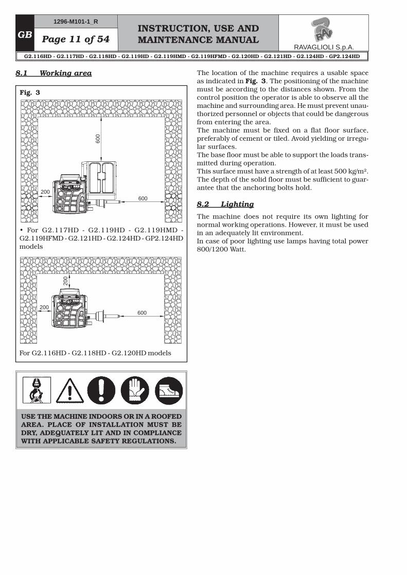
8.1 Working area
Fig. 3
USE THE MACHINE INDOORS OR IN A ROOFED AREA. PLACE OF INSTALLATION MUST BE DRY, ADEQUATELY LIT AND IN COMPLIANCE WITH APPLICABLE SAFETY REGULATIONS.
The location of the machine requires a usable space as indicated in Fig. 3. The positioning of the machine must be according to the distances shown. From the control position the operator is able to observe all the machine and surrounding area. He must prevent unau-thorized personnel or objects that could be dangerous from entering the area.The machine must be fixed on a flat floor surface, preferably of cement or tiled. Avoid yielding or irregu-lar surfaces.The base floor must be able to support the loads trans-mitted during operation. This surface must have a strength of at least 500 kg/m².The depth of the solid floor must be sufficient to guar-antee that the anchoring bolts hold.
8.2 Lighting
The machine does not require its own lighting for normal working operations. However, it must be used in an adequately lit environment.In case of poor lighting use lamps having total power 800/1200 Watt.
Page 12 of 54INSTRUCTION, USE AND MAINTENANCE MANUAL
GB
N.Code Description
1
1
1
1
1
GAR102
GAR111
129571492
1300A004
999072
Ring nut with handwheel + pusher ring
Cones + protection cup
Gauge
Weight pliers
Carriages counterweight
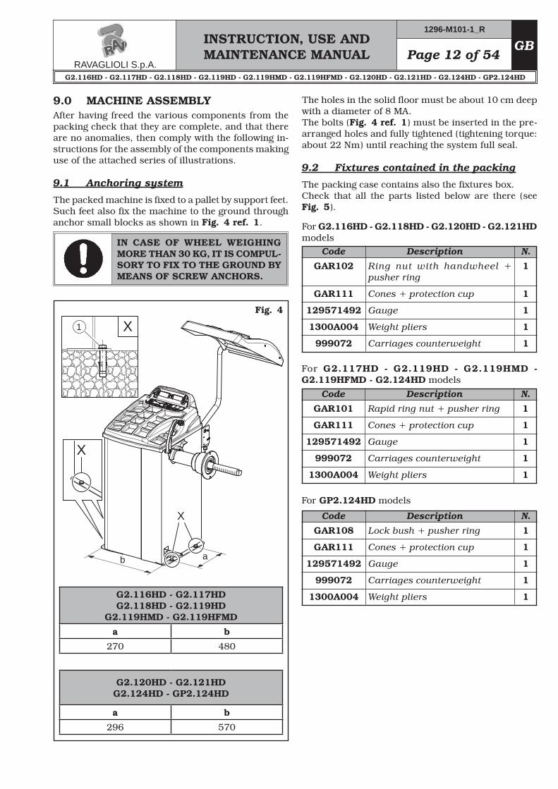
The holes in the solid floor must be about 10 cm deep with a diameter of 8 MA.The bolts (Fig. 4 ref. 1) must be inserted in the pre-arranged holes and fully tightened (tightening torque: about 22 Nm) until reaching the system full seal.
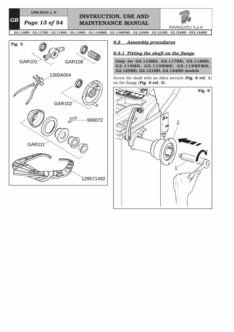
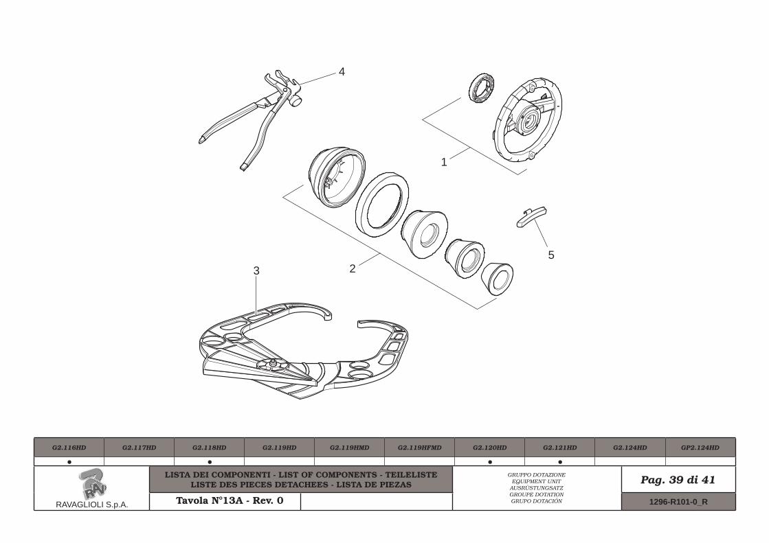
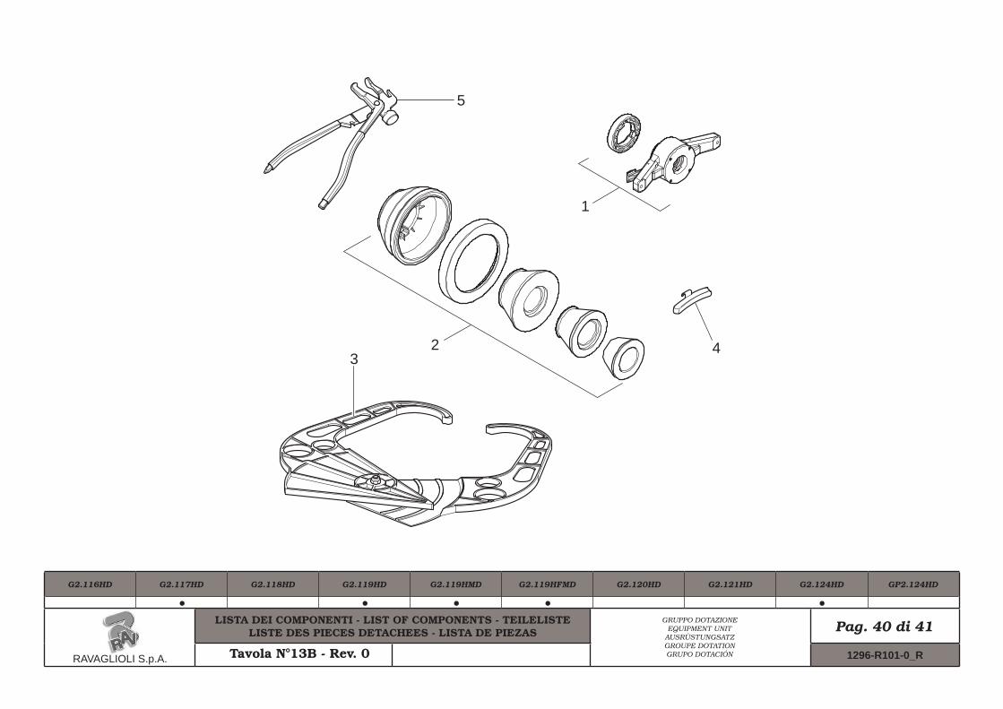
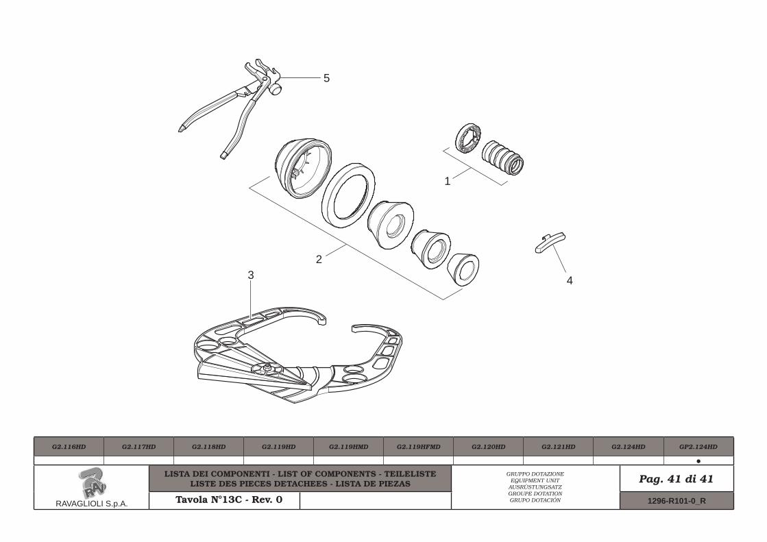
9.2 Fixtures contained in the packing
The packing case contains also the fixtures box.Check that all the parts listed below are there (see Fig. 5).
N.Code Description
1
1
1
1
1
GAR101
GAR111
129571492
999072
1300A004
Rapid ring nut + pusher ring
Cones + protection cup
Gauge
Carriages counterweight
Weight pliers
N.Code Description
1
1
1
1
1
GAR108
GAR111
129571492
999072
1300A004
Lock bush + pusher ring
Cones + protection cup
Gauge
Carriages counterweight
Weight pliers
9.0 MACHINE ASSEMBLYAfter having freed the various components from the packing check that they are complete, and that there are no anomalies, then comply with the following in-structions for the assembly of the components making use of the attached series of illustrations.
9.1 Anchoring system
The packed machine is fixed to a pallet by support feet. Such feet also fix the machine to the ground through anchor small blocks as shown in Fig. 4 ref._1.
IN CASE OF WHEEL WEIGHING MORE THAN 30 KG, IT IS COMPUL-SORY TO FIX TO THE GROUND BY MEANS OF SCREW ANCHORS.
Only for G2.116HD, G2.117HD, G2.118HD, G2.119HD, G2.119HMD, G2.119HFMD, G2.120HD, G2.121HD, G2.124HD models
Page 14 of 54INSTRUCTION, USE AND MAINTENANCE MANUAL
GB
Fig. 7
Fig. 8
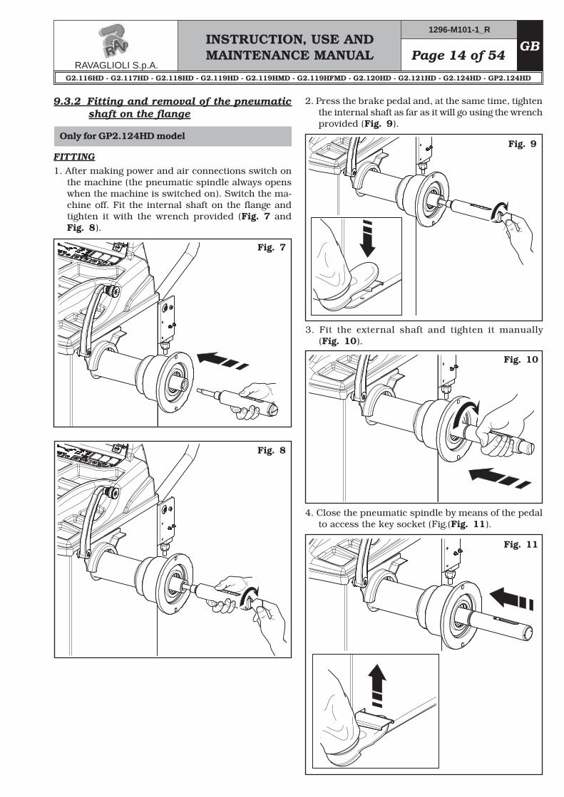
2. Press the brake pedal and, at the same time, tighten the internal shaft as far as it will go using the wrench provided (Fig. 9).
Fig. 9
3. Fit the external shaft and tighten it manually (Fig. 10).
Fig. 10
4. Close the pneumatic spindle by means of the pedal to access the key socket (Fig.(Fig. 11).
Fig. 11
FITTING1. After making power and air connections switch on
the machine (the pneumatic spindle always opens when the machine is switched on). Switch the ma-chine off. Fit the internal shaft on the flange and tighten it with the wrench provided (Fig. 7 and Fig. 8).
9.3.2 Fitting and removal of the pneumatic shaft on the flange
Only for G2.117HD - G2.119HD - G2.119HMD - G2.119HFMD models
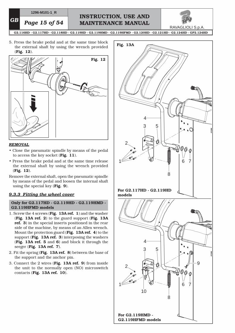
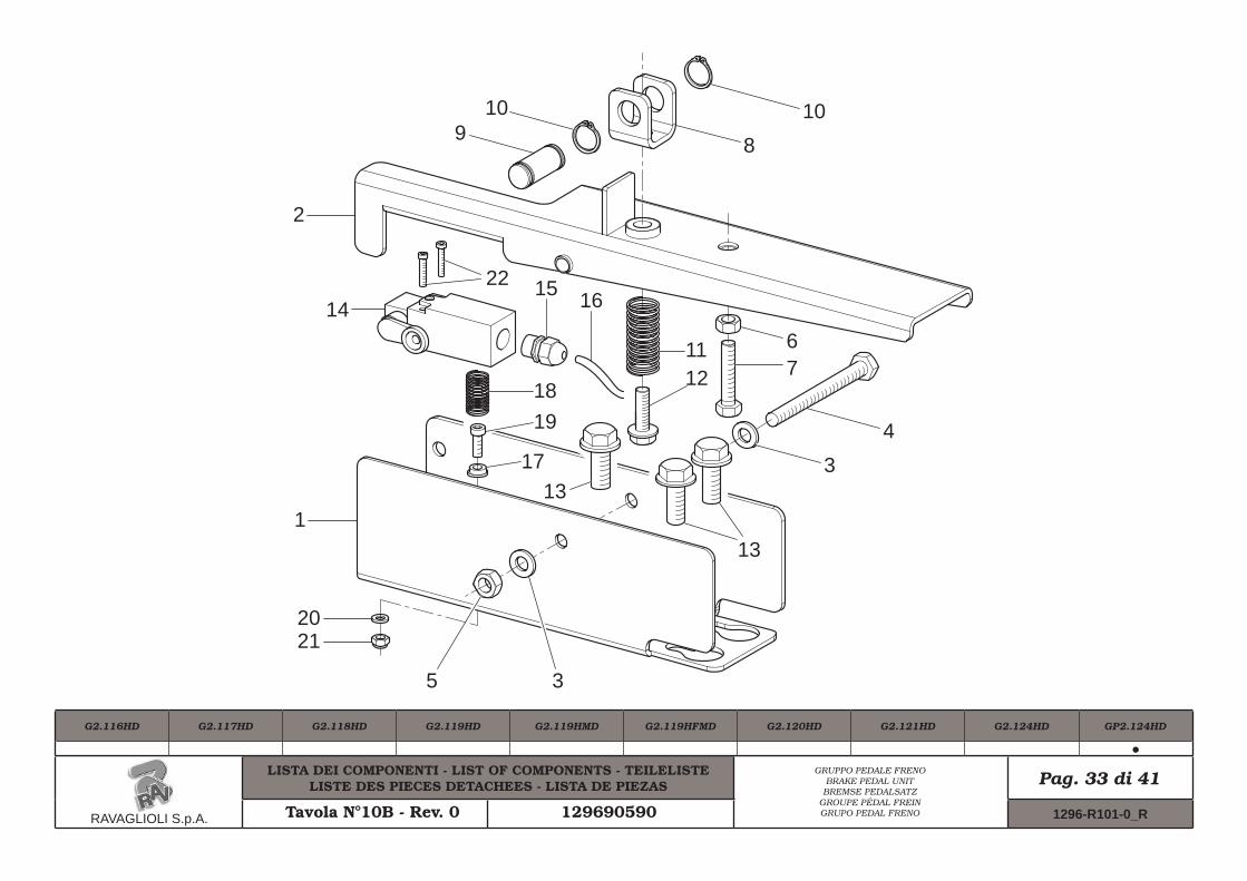
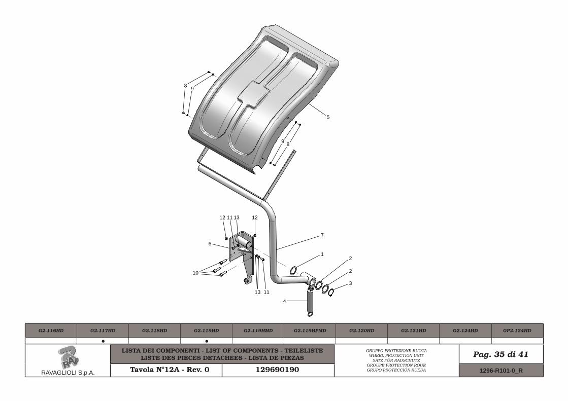
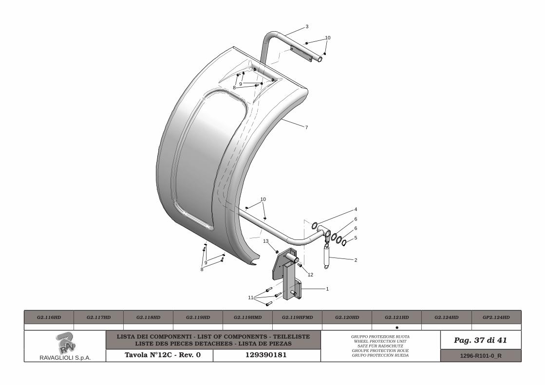
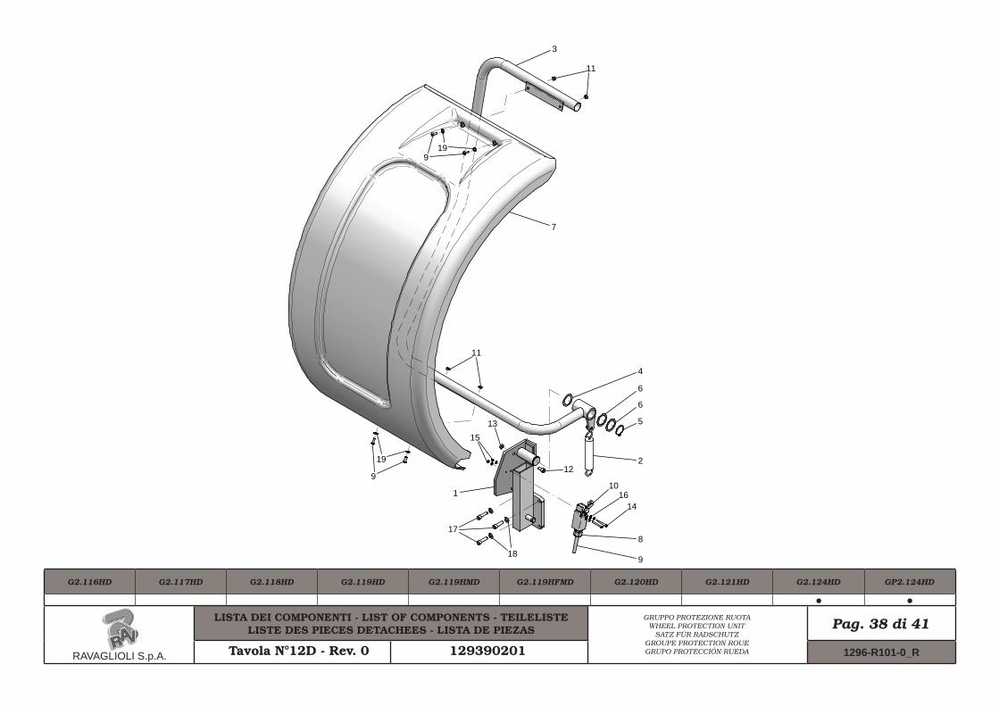
1. Screw the 4 screws (Fig. 13A ref. 1) and the washer (Fig. 13A ref. 2) to the guard support (Fig. 13A ref. 3) in the special inserts positioned in the rear side of the machine, by means of an Allen wrench. Mount the protection guard (Fig. 13A ref. 4) to the support (Fig. 13A ref. 3) interposing the washers (Fig. 13A ref. 5 and 6) and block it through the seeger (Fig. 13A ref. 7).
2. Fit the spring (Fig. 13A ref. 8) between the base of the support and the anchor pin.
3. Connect the 2 wires (Fig. 13A ref. 9) from inside the unit to the normally open (NO) microswitch contacts (Fig. 13A ref. 10).
For G2.117HD - G2.119HD models
For G2.119HMD - G2.119HFMD models
Page 16 of 54INSTRUCTION, USE AND MAINTENANCE MANUAL
GB
1
2
3
4
5
1
2
3
Fig. 13B
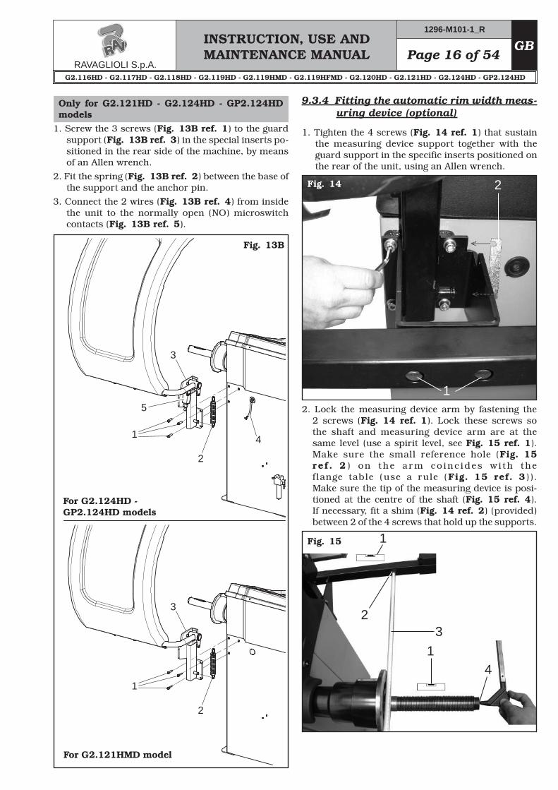
9.3.4 Fitting the automatic rim width meas-uring device (optional)
1. Tighten the 4 screws (Fig. 14 ref. 1) that sustain the measuring device support together with the guard support in the specific inserts positioned on the rear of the unit, using an Allen wrench.
Fig. 14
2. Lock the measuring device arm by fastening the 2 screws (Fig. 14 ref. 1). Lock these screws so the shaft and measuring device arm are at the same level (use a spirit level, see Fig. 15 ref. 1). Make sure the small reference hole (Fig. 15 re f . 2 ) on the arm co inc ides wi th the flange table (use a rule (Fig. 15 ref. 3)). Make sure the tip of the measuring device is posi-tioned at the centre of the shaft (Fig. 15 ref. 4). If necessary, fit a shim (Fig. 14 ref. 2) (provided) between 2 of the 4 screws that hold up the supports.
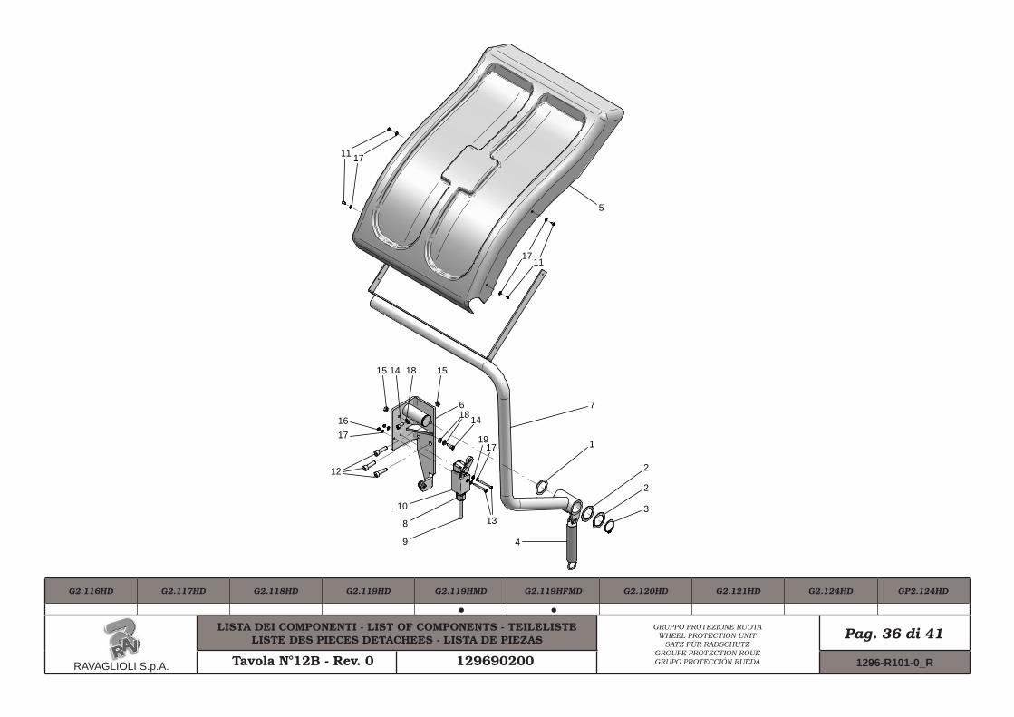
1. Screw the 3 screws (Fig. 13B ref. 1) to the guard support (Fig. 13B ref. 3) in the special inserts po-sitioned in the rear side of the machine, by means of an Allen wrench.
2. Fit the spring (Fig. 13B ref. 2) between the base of the support and the anchor pin.
3. Connect the 2 wires (Fig. 13B ref. 4) from inside the unit to the normally open (NO) microswitch contacts (Fig. 13B ref. 5).
For G2.124HD - GP2.124HD models
For G2.121HMD model
INSTRUCTION, USE AND MAINTENANCE MANUALGB Page 17 of 54
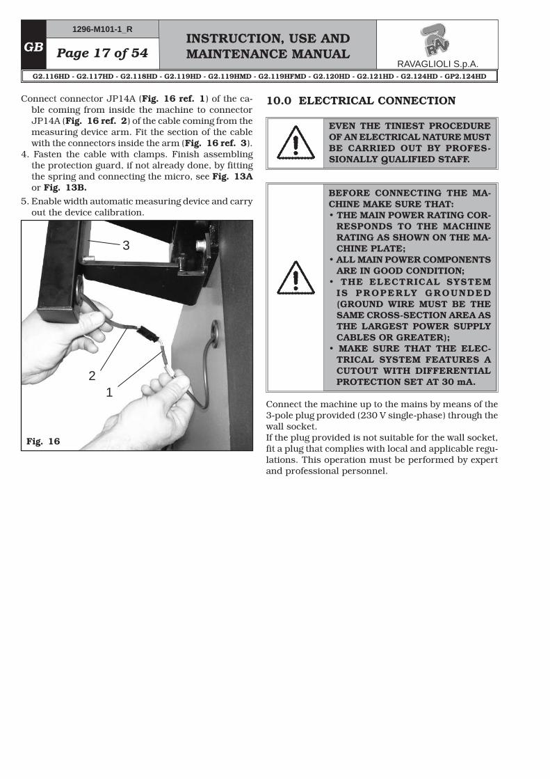
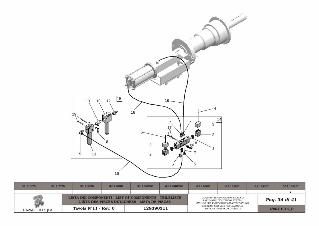
Connect connector JP14A (Fig. 16 ref. 1) of the ca-ble coming from inside the machine to connector JP14A (Fig. 16 ref. 2) of the cable coming from the measuring device arm. Fit the section of the cable with the connectors inside the arm (Fig. 16 ref. 3).
4. Fasten the cable with clamps. Finish assembling the protection guard, if not already done, by fitting the spring and connecting the micro, see Fig. 13A or Fig. 13B.
5. Enable width automatic measuring device and carry out the device calibration.
Fig. 16
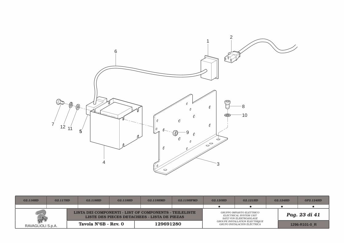
10.0 ELECTRICAL CONNECTION
EVEN THE TINIEST PROCEDURE OF AN ELECTRICAL NATURE MUST BE CARRIED OUT BY PROFES-SIONALLY QUALIFIED STAFF.
BEFORE CONNECTING THE MA-CHINE MAKE SURE THAT:• THE MAIN POWER RATING COR-
RESPONDS TO THE MACHINE RATING AS SHOWN ON THE MA-CHINE PLATE;
• ALL MAIN POWER COMPONENTS ARE IN GOOD CONDITION;
• THE ELECTRICAL SYSTEM IS PROPERLY GROUNDED (GROUND WIRE MUST BE THE SAME CROSS-SECTION AREA AS THE LARGEST POWER SUPPLY CABLES OR GREATER);
• MAKE SURE THAT THE ELEC-TRICAL SYSTEM FEATURES A CUTOUT WITH DIFFERENTIAL PROTECTION SET AT 30 mA.
Connect the machine up to the mains by means of the 3-pole plug provided (230 V single-phase) through the wall socket.If the plug provided is not suitable for the wall socket, fit a plug that complies with local and applicable regu-lations. This operation must be performed by expert and professional personnel.
Page 18 of 54INSTRUCTION, USE AND MAINTENANCE MANUAL
GB
A
FIT A TYPE-APPROVED (AS RE-PORTED BEFORE) PLUG TO THE MACHINE CABLE (THE GROUND WIRE IS YELLOW/GREEN AND MUST NEVER BE CONNECTED TO THE PHASE LEADS). MAKE SURE THAT THE ELECTRICAL SYSTEM IS COMPATIBLE WITH THE RATED POWER ABSORPTION SPECIFIED IN THIS MANUAL AND APT TO ENSURE THAT VOLTAGE DROP UNDER FULL LOAD WILL NOT EXCEED 4% OF RATED VOLTAGE (10% UPON START-UP).
10.1 Electrical checks
BEFORE STARTING UP THE WHEEL-BALANCER, BE SURE TO BECOME FAMILIAR WITH THE LO-CATION AND OPERATION OF ALL CONTROLS AND CHECK THEIR PROPER OPERATION (SEE PAR. “CONTROLS”).
CARRY OUT A DAILY CHECK OF MAINTAINED-TYPE CONTROLS CORRECT FUNCTIONING, BEFORE STARTING MACHINE OPERATION.
FAILURE TO OBSERVE THE ABOVE INSTRUCTIONS WILL IMMEDIATE-LY INVALIDATE THE WARRANTY.
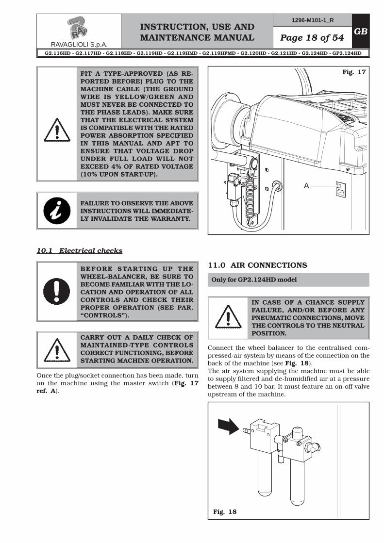
Once the plug/socket connection has been made, turn on the machine using the master switch (Fig. 17 ref. A).
Fig. 17
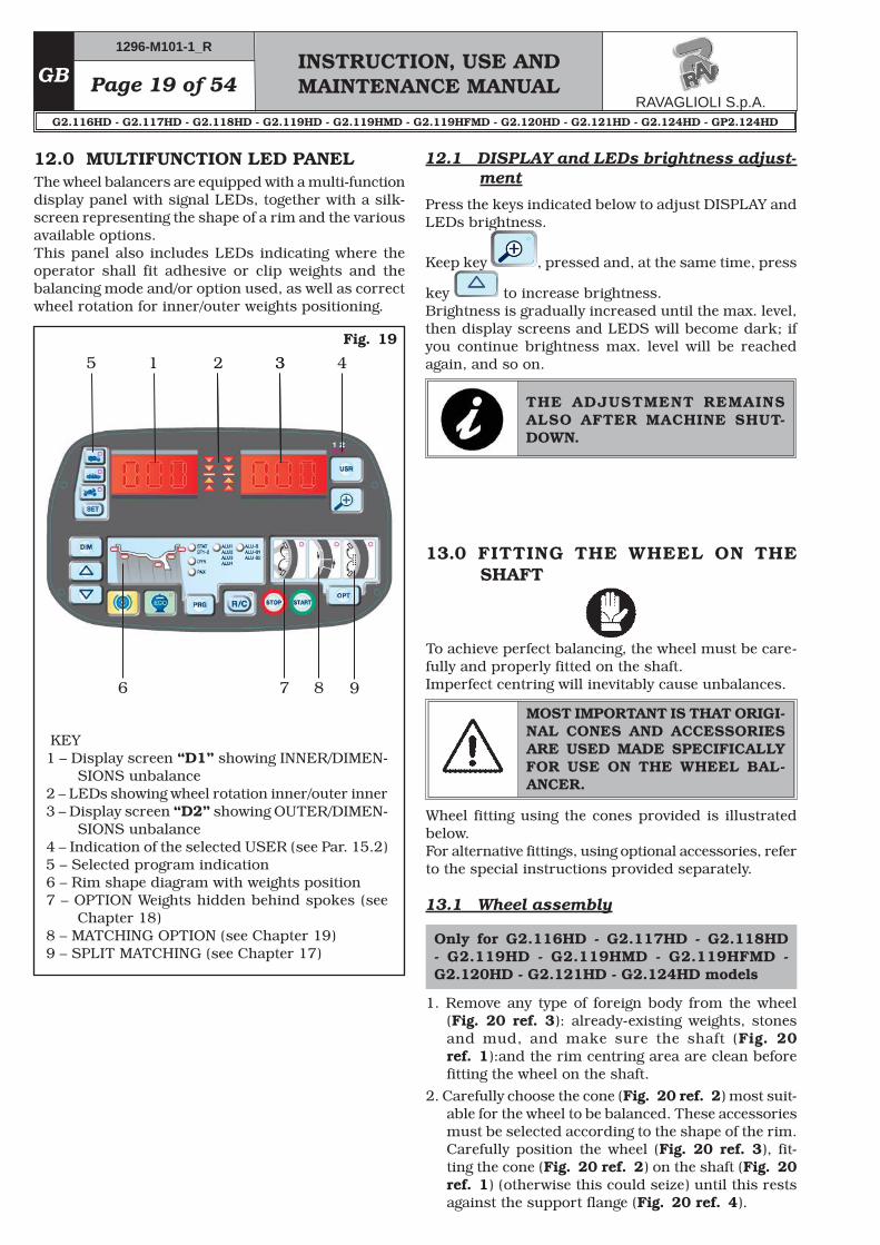
Fig. 18
IN CASE OF A CHANCE SUPPLY FAILURE, AND/OR BEFORE ANY PNEUMATIC CONNECTIONS, MOVE THE CONTROLS TO THE NEUTRAL POSITION.
Connect the wheel balancer to the centralised com-pressed-air system by means of the connection on the back of the machine (see Fig. 18).The air system supplying the machine must be able to supply filtered and de-humidified air at a pressure between 8 and 10 bar. It must feature an on-off valve upstream of the machine.
INSTRUCTION, USE AND MAINTENANCE MANUALGB Page 19 of 54
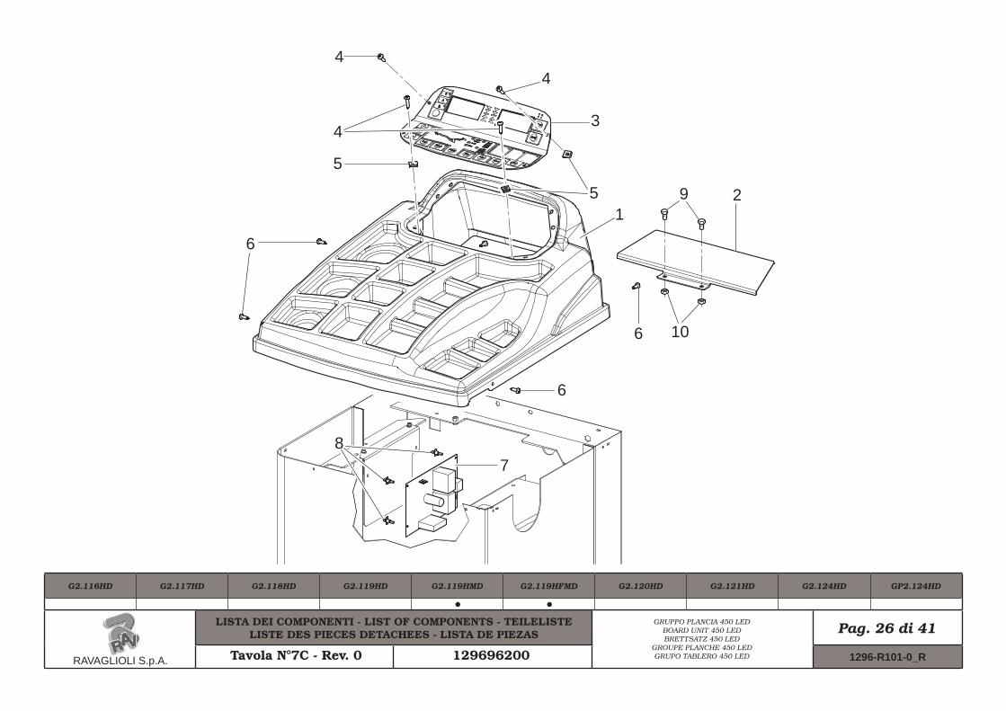
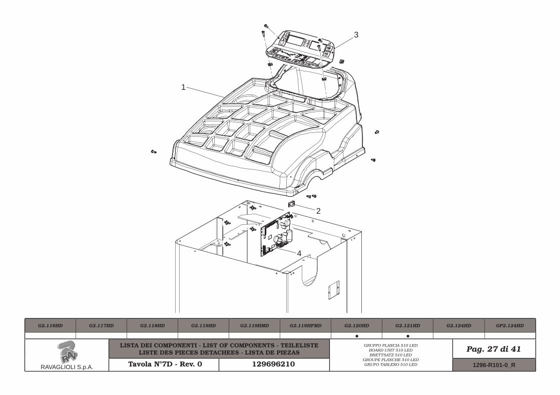
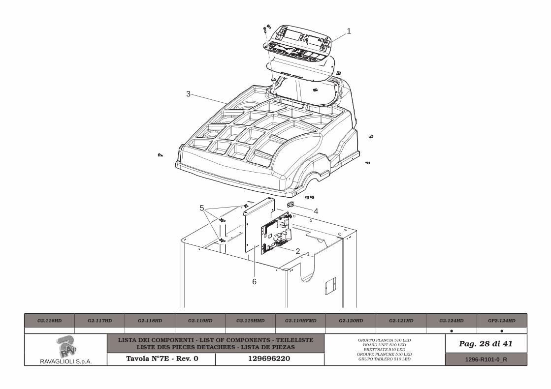
12.0 MULTIFUNCTION LED PANELThe wheel balancers are equipped with a multi-function display panel with signal LEDs, together with a silk-screen representing the shape of a rim and the various available options.This panel also includes LEDs indicating where the operator shall fit adhesive or clip weights and the balancing mode and/or option used, as well as correct wheel rotation for inner/outer weights positioning.
SIONS unbalance4 – Indication of the selected USER (see Par. 15.2)5 – Selected program indication6 – Rim shape diagram with weights position7 – OPTION Weights hidden behind spokes (see
Chapter 18)8 – MATCHING OPTION (see Chapter 19)9 – SPLIT MATCHING (see Chapter 17)
2 33 45
6 7 8 9
12.1 DISPLAY and LEDs brightness adjust-ment
Press the keys indicated below to adjust DISPLAY and LEDs brightness.
Keep key , pressed and, at the same time, press
key to increase brightness.Brightness is gradually increased until the max. level, then display screens and LEDS will become dark; if you continue brightness max. level will be reached again, and so on.
THE ADJUSTMENT REMAINS ALSO AFTER MACHINE SHUT-DOWN.
13.0 FITTING THE WHEEL ON THE SHAFT
To achieve perfect balancing, the wheel must be care-fully and properly fitted on the shaft.Imperfect centring will inevitably cause unbalances.
MOST IMPORTANT IS THAT ORIGI-NAL CONES AND ACCESSORIES ARE USED MADE SPECIFICALLY FOR USE ON THE WHEEL BAL-ANCER.
Wheel fitting using the cones provided is illustrated below.For alternative fittings, using optional accessories, refer to the special instructions provided separately.
13.1 Wheel assembly
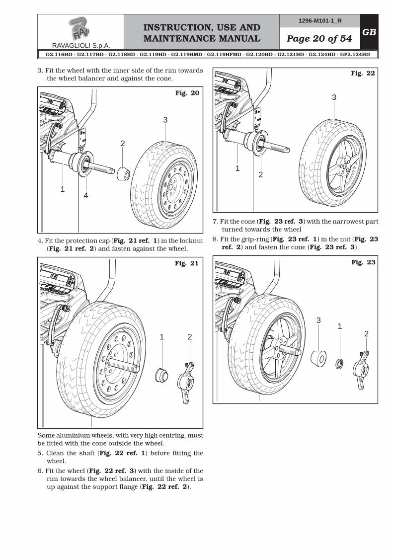
1. Remove any type of foreign body from the wheel (Fig. 20 ref. 3): already-existing weights, stones and mud, and make sure the shaft (Fig. 20 ref. 1):and the rim centring area are clean before fitting the wheel on the shaft.
2. Carefully choose the cone (Fig. 20 ref. 2) most suit-able for the wheel to be balanced. These accessories must be selected according to the shape of the rim. Carefully position the wheel (Fig. 20 ref. 3), fit-ting the cone (Fig. 20 ref. 2) on the shaft (Fig. 20 ref. 1) (otherwise this could seize) until this rests against the support flange (Fig. 20 ref. 4).
INSTRUCTION, USE AND MAINTENANCE MANUALGB Page 21 of 54
1 2
2
3
4 1
3
2 1
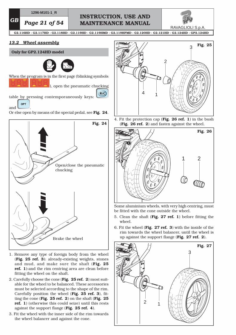
13.2 Wheel assembly
1. Remove any type of foreign body from the wheel (Fig. 25 ref. 3): already-existing weights, stones and mud, and make sure the shaft (Fig. 25 ref. 1):and the rim centring area are clean before fitting the wheel on the shaft.
2. Carefully choose the cone (Fig. 25 ref. 2) most suit-able for the wheel to be balanced. These accessories must be selected according to the shape of the rim. Carefully position the wheel (Fig. 25 ref. 3), fit-ting the cone (Fig. 25 ref. 2) on the shaft (Fig. 25 ref. 1) (otherwise this could seize) until this rests against the support flange (Fig. 25 ref. 4).
3. Fit the wheel with the inner side of the rim towards the wheel balancer and against the cone.
Fig. 24
Fig. 25
4. Fit the protection cap (Fig. 26 ref. 1) in the bush (Fig. 26 ref. 2) and fasten against the wheel.
Some aluminium wheels, with very high centring, must be fitted with the cone outside the wheel.5. Clean the shaft (Fig. 27 ref. 1) before fitting the
wheel.6. Fit the wheel (Fig. 27 ref. 3) with the inside of the
rim towards the wheel balancer, until the wheel is up against the support flange (Fig. 27 ref. 2).
Fig. 26
Fig. 27
Open/close the pneumatic chucking
Brake the wheel
When the program is in the first page (blinking symbols
), open the pneumatic chucking
table by pressing contemporaneously keys:
and .Or else open by means of the special pedal, see Fig. 24.
Page 22 of 54INSTRUCTION, USE AND MAINTENANCE MANUAL
GB
12
3
Close the pneumatic chucking table from the program
start page, by pressing cat the same time keys:
and . Or else close by means of the special pedal.
DURING CHUCKING TABLE OPEN-ING/CLOSING OPERATIONS, BE CAREFUL TO KEEP YOUR HANDS AND OTHER PARTS OF THE BODY AWAY FROM THE MOVING CHUCK-ING TABLE.
14.0 SWITCHING THE MACHINE ON AND OFF
The ON/OFF master switch is located on the rear of the machine.To start the machine and access the program, switch on the system by turning the master switch.
IN THE CASE OF PNEUMATIC MODELS, ON STARTING, THE PNEUMATIC CHUCKING TABLE IS ALWAYS OPENED. ALWAYS KEEP YOUR HANDS AND OTHER PARTS OF THE BODY AWAY FROM THE MOVING CHUCKING TABLE.ALSO BE CAREFUL, IF A WHEEL IS ALREADY FITTED ON THE SHAFT AS THIS COULD BE FORCED OFF THE SHAFT DURING CHUCKING TABLE OPENING.
Wait a few seconds for the operating program to load and for the first program page to appear on the dis-
play screens D1 and D2: (flashing dashes:
)
Use operative keyboard keys (see Fig. 19) to use all machine available functions.
7. Fit the cone (Fig. 28 ref. 3) with the narrowest part turned towards the wheel
8. Fit the grip-ring (Fig. 28 ref. 1) in the bush (Fig. 28 ref. 2) and fasten the cone.
Fig. 28
Key for balancing cycle start
Key for procedure pause / stop
Key for data recalculation / confirmation
Key for wheel dimensions entering
Keys to increase / decrease entered values
Key for MOTORBIKE wheel cycle
Key for balancing program selection
Key for Option selection
Key for Eco-Weight procedure
“Zoom” key for not rounded-off unbalance displaying
INSTRUCTION, USE AND MAINTENANCE MANUALGB Page 23 of 54
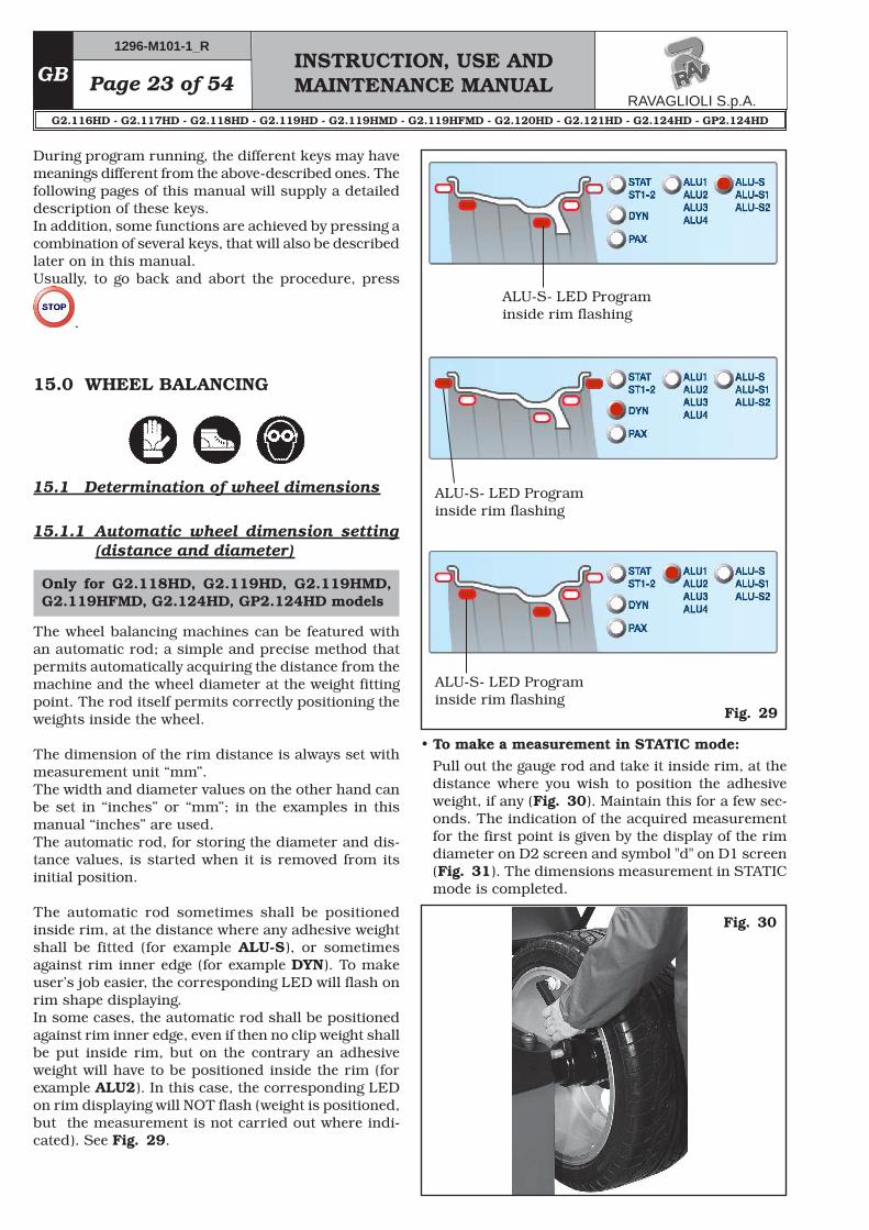
15.1 Determination of wheel dimensions
15.1.1 Automatic wheel dimension setting (distance and diameter)
Fig. 29
ALU-S- LED Program inside rim flashing
ALU-S- LED Program inside rim flashing
ALU-S- LED Program inside rim flashing
• To make a measurement in STATIC mode:Pull out the gauge rod and take it inside rim, at the distance where you wish to position the adhesive weight, if any (Fig. 30). Maintain this for a few sec-onds. The indication of the acquired measurement for the first point is given by the display of the rim diameter on D2 screen and symbol "d" on D1 screen (Fig. 31). The dimensions measurement in STATIC mode is completed.
Fig. 30
During program running, the different keys may have meanings different from the above-described ones. The following pages of this manual will supply a detailed description of these keys.In addition, some functions are achieved by pressing a combination of several keys, that will also be described later on in this manual.Usually, to go back and abort the procedure, press
.
15.0 WHEEL BALANCING
The wheel balancing machines can be featured with an automatic rod; a simple and precise method that permits automatically acquiring the distance from the machine and the wheel diameter at the weight fitting point. The rod itself permits correctly positioning the weights inside the wheel.
The dimension of the rim distance is always set with measurement unit “mm”. The width and diameter values on the other hand can be set in “inches” or “mm”; in the examples in this manual “inches” are used. The automatic rod, for storing the diameter and dis-tance values, is started when it is removed from its initial position.
The automatic rod sometimes shall be positioned inside rim, at the distance where any adhesive weight shall be fitted (for example ALU-S), or sometimes against rim inner edge (for example DYN). To make user’s job easier, the corresponding LED will flash on rim shape displaying. In some cases, the automatic rod shall be positioned against rim inner edge, even if then no clip weight shall be put inside rim, but on the contrary an adhesive weight will have to be positioned inside the rim (for example ALU2). In this case, the corresponding LED on rim displaying will NOT flash (weight is positioned, but the measurement is not carried out where indi-cated). See Fig. 29.
Only for G2.118HD, G2.119HD, G2.119HMD, G2.119HFMD, G2.124HD, GP2.124HD models
Page 24 of 54INSTRUCTION, USE AND MAINTENANCE MANUAL
GB
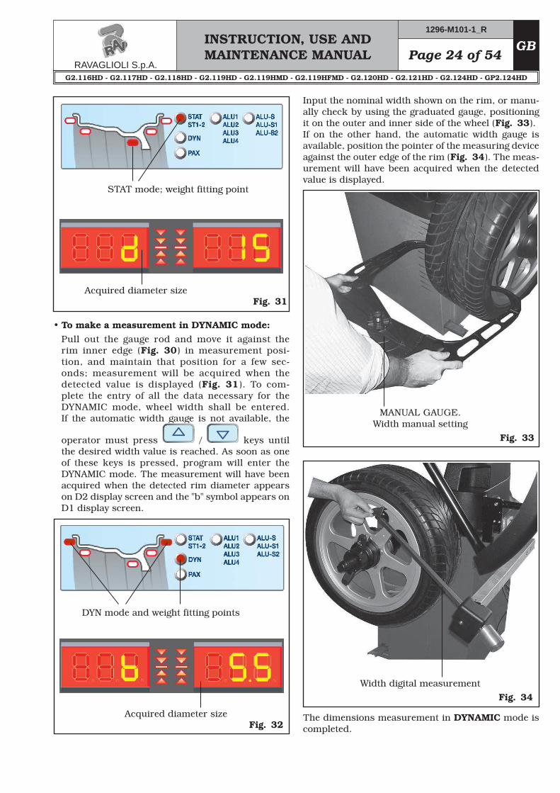
Fig. 31
STAT mode; weight fitting point
Acquired diameter size
• To make a measurement in DYNAMIC mode:Pull out the gauge rod and move it against the rim inner edge (Fig. 30) in measurement posi-tion, and maintain that position for a few sec-onds; measurement will be acquired when the detected value is displayed (Fig. 31). To com-plete the entry of all the data necessary for the DYNAMIC mode, wheel width shall be entered. If the automatic width gauge is not available, the
operator must press / keys until the desired width value is reached. As soon as one of these keys is pressed, program will enter the DYNAMIC mode. The measurement will have been acquired when the detected rim diameter appears on D2 display screen and the "b" symbol appears on D1 display screen.
Fig. 32
DYN mode and weight fitting points
Acquired diameter size
Input the nominal width shown on the rim, or manu-ally check by using the graduated gauge, positioning it on the outer and inner side of the wheel (Fig. 33). If on the other hand, the automatic width gauge is available, position the pointer of the measuring device against the outer edge of the rim (Fig. 34). The meas-urement will have been acquired when the detected value is displayed.
Fig. 33
MANUAL GAUGE.Width manual setting
Fig. 34Width digital measurement
The dimensions measurement in DYNAMIC mode is completed.
INSTRUCTION, USE AND MAINTENANCE MANUALGB Page 25 of 54
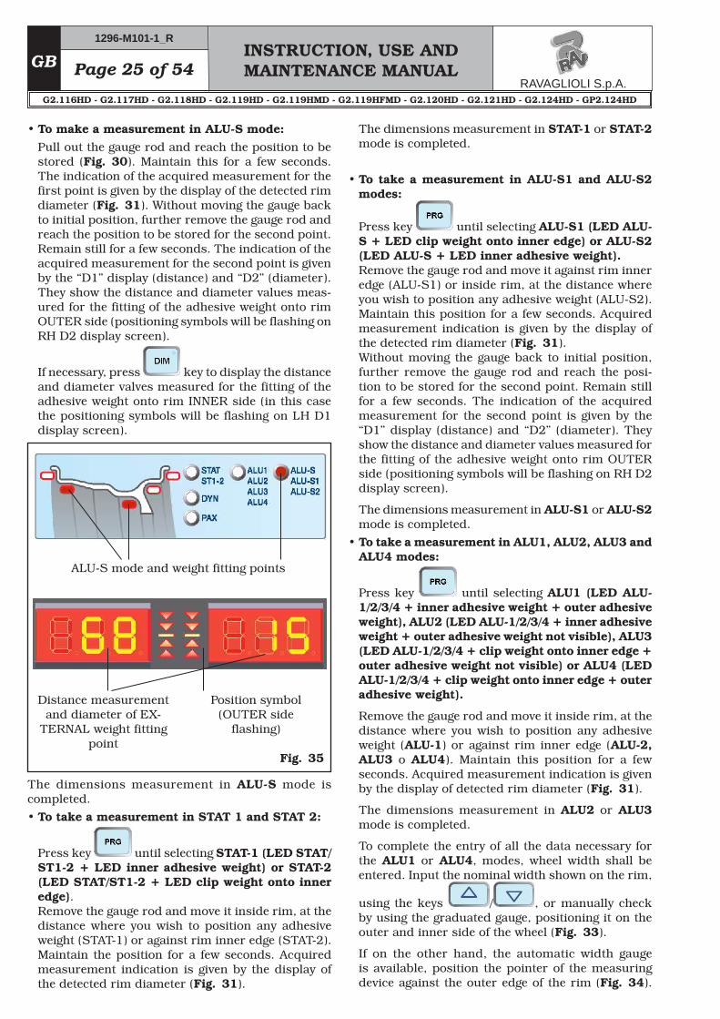
• To make a measurement in ALU-S mode:Pull out the gauge rod and reach the position to be stored (Fig. 30). Maintain this for a few seconds. The indication of the acquired measurement for the first point is given by the display of the detected rim diameter (Fig. 31). Without moving the gauge back to initial position, further remove the gauge rod and reach the position to be stored for the second point. Remain still for a few seconds. The indication of the acquired measurement for the second point is given by the “D1” display (distance) and “D2” (diameter). They show the distance and diameter values meas-ured for the fitting of the adhesive weight onto rim OUTER side (positioning symbols will be flashing on RH D2 display screen).
If necessary, press key to display the distance and diameter valves measured for the fitting of the adhesive weight onto rim INNER side (in this case the positioning symbols will be flashing on LH D1 display screen).
Fig. 35
ALU-S mode and weight fitting points
Distance measurement and diameter of EX-
TERNAL weight fitting point
Position symbol (OUTER side
flashing)
The dimensions measurement in ALU-S mode is completed.• To take a measurement in STAT 1 and STAT 2:
Press key until selecting STAT-1 (LED STAT/ST1-2 + LED inner adhesive weight) or STAT-2 (LED STAT/ST1-2 + LED clip weight onto inner edge).Remove the gauge rod and move it inside rim, at the distance where you wish to position any adhesive weight (STAT-1) or against rim inner edge (STAT-2). Maintain the position for a few seconds. Acquired measurement indication is given by the display of the detected rim diameter (Fig. 31).
The dimensions measurement in STAT-1 or STAT-2 mode is completed.
• To take a measurement in ALU-S1 and ALU-S2 modes:
Press key until selecting ALU-S1 (LED ALU-S + LED clip weight onto inner edge) or ALU-S2 (LED ALU-S + LED inner adhesive weight).Remove the gauge rod and move it against rim inner edge (ALU-S1) or inside rim, at the distance where you wish to position any adhesive weight (ALU-S2). Maintain this position for a few seconds. Acquired measurement indication is given by the display of the detected rim diameter (Fig. 31). Without moving the gauge back to initial position, further remove the gauge rod and reach the posi-tion to be stored for the second point. Remain still for a few seconds. The indication of the acquired measurement for the second point is given by the “D1” display (distance) and “D2” (diameter). They show the distance and diameter values measured for the fitting of the adhesive weight onto rim OUTER side (positioning symbols will be flashing on RH D2 display screen).
The dimensions measurement in ALU-S1 or ALU-S2 mode is completed.
• To take a measurement in ALU1, ALU2, ALU3 and ALU4 modes:
Remove the gauge rod and move it inside rim, at the distance where you wish to position any adhesive weight (ALU-1) or against rim inner edge (ALU-2, ALU3 o ALU4). Maintain this position for a few seconds. Acquired measurement indication is given by the display of detected rim diameter (Fig. 31).
The dimensions measurement in ALU2 or ALU3 mode is completed.
To complete the entry of all the data necessary for the ALU1 or ALU4, modes, wheel width shall be entered. Input the nominal width shown on the rim,
using the keys / , or manually check by using the graduated gauge, positioning it on the outer and inner side of the wheel (Fig. 33).
If on the other hand, the automatic width gauge is available, position the pointer of the measuring device against the outer edge of the rim (Fig. 34).
Page 26 of 54INSTRUCTION, USE AND MAINTENANCE MANUAL
GB
The measurement will have been acquired when the detected value is displayed.
The dimensions measurement in ALU1 or ALU4 mode is completed.
15.1.2 Manual setting of wheel dimensions
In case the operator wants to edit and/or manually enter the wheel dimensions, proceed as follows:
- from wheel dimensions page, press key to select the value to be edited or set; The digit on the display corresponding to the value to be edited is flashing.
- Press the / keys until the desired value is reached.
- Press the key to confirm and to move to the next value to be edited or set.
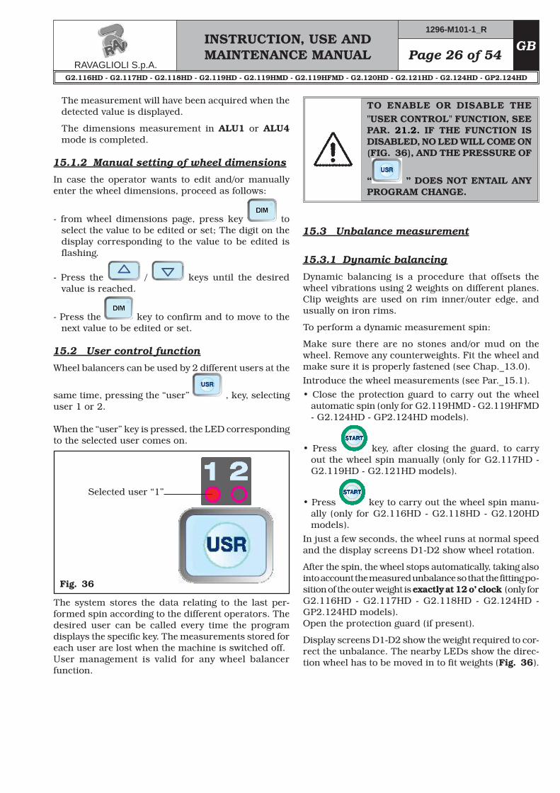
15.2 User control function
Wheel balancers can be used by 2 different users at the
same time, pressing the “user” , key, selecting user 1 or 2.
When the “user” key is pressed, the LED corresponding to the selected user comes on.
Fig. 36
Selected user “1”
The system stores the data relating to the last per-formed spin according to the different operators. The desired user can be called every time the program displays the specific key. The measurements stored for each user are lost when the machine is switched off. User management is valid for any wheel balancer function.
TO ENABLE OR DISABLE THE "USER CONTROL" FUNCTION, SEE PAR. 21.2. IF THE FUNCTION IS DISABLED, NO LED WILL COME ON (FIG. 36), AND THE PRESSURE OF
Dynamic balancing is a procedure that offsets the wheel vibrations using 2 weights on different planes. Clip weights are used on rim inner/outer edge, and usually on iron rims.
To perform a dynamic measurement spin:
Make sure there are no stones and/or mud on the wheel. Remove any counterweights. Fit the wheel and make sure it is properly fastened (see Chap._13.0).Introduce the wheel measurements (see Par._15.1).• Close the protection guard to carry out the wheel
• Press key, after closing the guard, to carry out the wheel spin manually (only for G2.117HD - G2.119HD - G2.121HD models).
• Press key to carry out the wheel spin manu-ally (only for G2.116HD - G2.118HD - G2.120HD models).
In just a few seconds, the wheel runs at normal speed and the display screens D1-D2 show wheel rotation.
After the spin, the wheel stops automatically, taking also into account the measured unbalance so that the fitting po-sition of the outer weight is exactly at 12 o’ clock (only for G2.116HD - G2.117HD - G2.118HD - G2.124HD - GP2.124HD models).Open the protection guard (if present).
Display screens D1-D2 show the weight required to cor-rect the unbalance. The nearby LEDs show the direc-tion wheel has to be moved in to fit weights (Fig. 36).
INSTRUCTION, USE AND MAINTENANCE MANUALGB Page 27 of 54
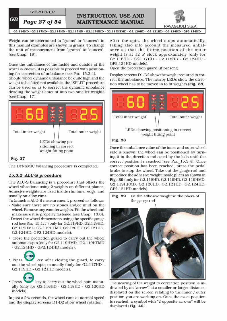
Fig. 37
Total inner weight
LEDs showing po-sitioning in correct weight fitting point
Total outer weight
Fig. 38
Total inner weight
LEDs showing positioning in correct weight fitting point
Total outer weight
Fig. 39 Fit the adhesive weight in the pliers of the gauge rod
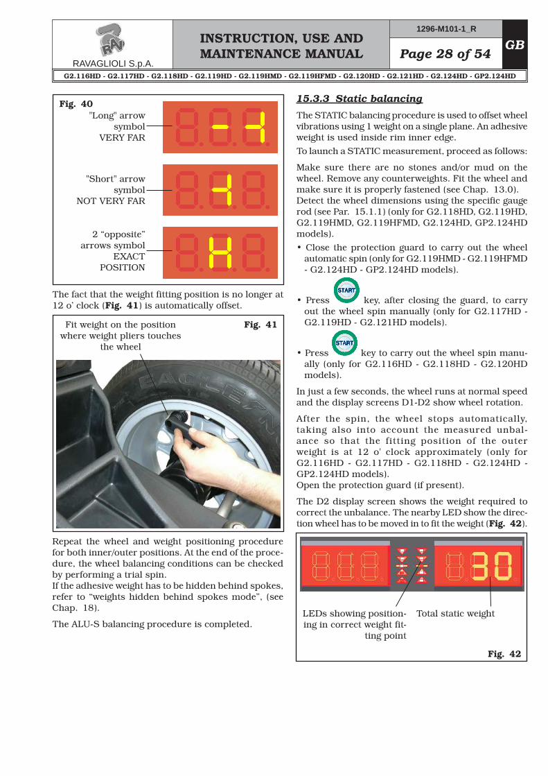
The nearing of the weight to correction position is in-dicated by an “arrow”, at a smaller or larger distance, displayed on the screen relating to the inner / outer position you are working on. Once the exact position is reached, a symbol with “2 opposite arrows” will be displayed (Fig. 40).
Weight can be determined in "grams" or "ounces"; in this manual examples are shown in grams. To change the unit of measurement from "grams" to "ounces", (see Chap. 19).
Once the unbalance of the inside and outside of the wheel is known, it is possible to proceed with position-ing for correction of unbalance (see Par. 15.3.4).Should wheel dynamic unbalance be quite high and the weight to be fitted not available, the “SPLIT” procedure can be used so as to correct the dynamic unbalance dividing the weight amount into two smaller weights (see Chap. 17).
The ALU-S balancing is a procedure that offsets the wheel vibrations using 2 weights on different planes. Adhesive weights are used inside rim inner edge, and usually on alloy rims.To launch a ALU-S measurement, proceed as follows:- Make sure there are no stones and/or mud on the
wheel. Remove any counterweights. Fit the wheel and make sure it is properly fastened (see Chap. 13.0).
- Detect the wheel dimensions using the specific gauge rod (see Par. 15.1.1) (only for G2.118HD, G2.119HD, G2.119HMD, G2.119HFMD, G2.120HD, G2.121HD, G2.124HD, GP2.124HD models).
• Close the protection guard to carry out the wheel automatic spin (only for G2.119HMD - G2.119HFMD - G2.124HD - GP2.124HD models).
• Press key, after closing the guard, to carry out the wheel spin manually (only for G2.117HD - G2.119HD - G2.121HD models).
• Press key to carry out the wheel spin manu-ally (only for G2.116HD - G2.118HD - G2.120HD models).
In just a few seconds, the wheel runs at normal speed and the display screens D1-D2 show wheel rotation.
Once the unbalance value of the inner and outer wheel side is known, the wheel can be positioned by turn-ing it in the direction indicated by the leds until the correct position is reached (see Par._15.3.4). Once correct position has been reached, press the pedal brake to stop the wheel. Take out the gauge rod and introduce the adhesive weight inside pliers as shown in Fig. 39 (only for G2.118HD, G2.119HD, G2.119HMD, G2.119HFMD, G2.120HD, G2.121HD, G2.124HD, GP2.124HD models).
After the spin, the wheel stops automatically, taking also into account the measured unbal-ance so that the fitting position of the outer weight is at 12 o' clock approximately (only for G2.116HD - G2.117HD - G2.118HD - G2.124HD - GP2.124HD models). Open the protection guard (if present).
Display screens D1-D2 show the weight required to cor-rect the unbalance. The nearby LEDs show the direc-tion wheel has to be moved in to fit weights (Fig. 38).
Page 28 of 54INSTRUCTION, USE AND MAINTENANCE MANUAL
GB
Fig. 40"Long" arrow
symbol VERY FAR
"Short" arrow symbol
NOT VERY FAR
2 “opposite” arrows symbol
EXACT POSITION
The fact that the weight fitting position is no longer at 12 o’ clock (Fig. 41) is automatically offset.
Fig. 41Fit weight on the position where weight pliers touches
the wheel
Repeat the wheel and weight positioning procedure for both inner/outer positions. At the end of the proce-dure, the wheel balancing conditions can be checked by performing a trial spin.If the adhesive weight has to be hidden behind spokes, refer to “weights hidden behind spokes mode”, (see Chap. 18).
The STATIC balancing procedure is used to offset wheel vibrations using 1 weight on a single plane. An adhesive weight is used inside rim inner edge.To launch a STATIC measurement, proceed as follows:
Make sure there are no stones and/or mud on the wheel. Remove any counterweights. Fit the wheel and make sure it is properly fastened (see Chap. 13.0).Detect the wheel dimensions using the specific gauge rod (see Par. 15.1.1) (only for G2.118HD, G2.119HD, G2.119HMD, G2.119HFMD, G2.124HD, GP2.124HD models).• Close the protection guard to carry out the wheel
• Press key, after closing the guard, to carry out the wheel spin manually (only for G2.117HD - G2.119HD - G2.121HD models).
• Press key to carry out the wheel spin manu-ally (only for G2.116HD - G2.118HD - G2.120HD models).
In just a few seconds, the wheel runs at normal speed and the display screens D1-D2 show wheel rotation.
After the spin, the wheel stops automatically, taking also into account the measured unbal-ance so that the fitting position of the outer weight is at 12 o' clock approximately (only for G2.116HD - G2.117HD - G2.118HD - G2.124HD - GP2.124HD models). Open the protection guard (if present).
The D2 display screen shows the weight required to correct the unbalance. The nearby LED show the direc-tion wheel has to be moved in to fit the weight (Fig. 42).
INSTRUCTION, USE AND MAINTENANCE MANUALGB Page 29 of 54
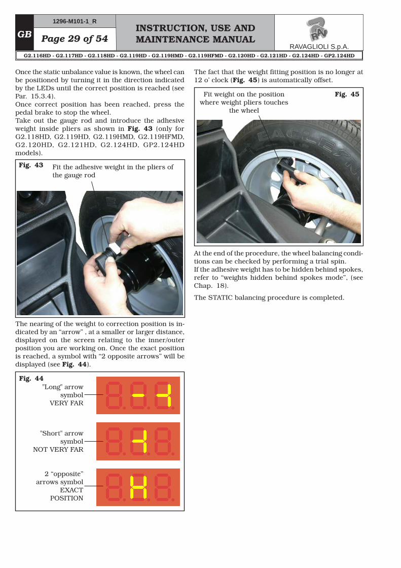
Fit the adhesive weight in the pliers of the gauge rod
The nearing of the weight to correction position is in-dicated by an “arrow” , at a smaller or larger distance, displayed on the screen relating to the inner/outer position you are working on. Once the exact position is reached, a symbol with “2 opposite arrows” will be displayed (see Fig. 44).
Fig. 43
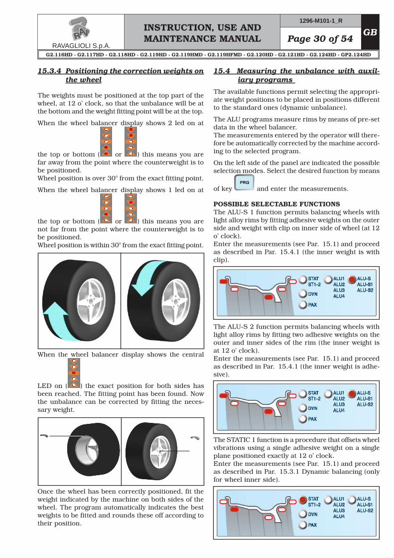
Fig. 44"Long" arrow
symbol VERY FAR
"Short" arrow symbol
NOT VERY FAR
2 “opposite” arrows symbol
EXACT POSITION
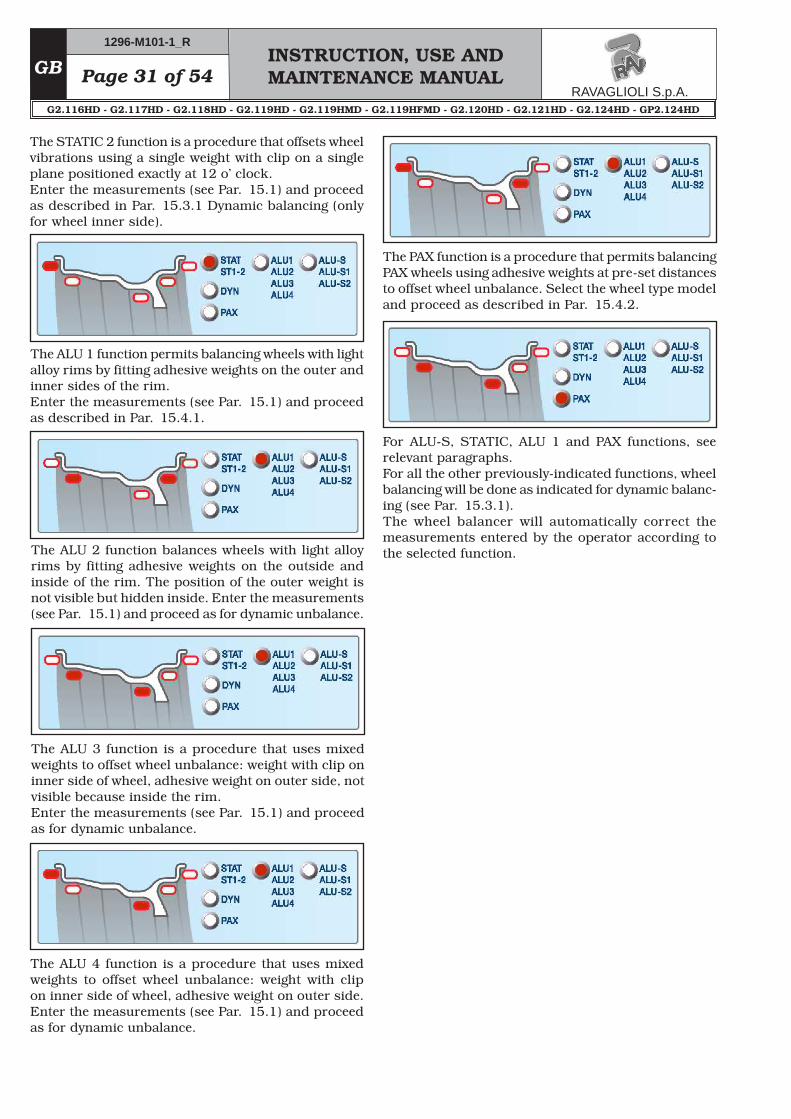
The fact that the weight fitting position is no longer at 12 o’ clock (Fig. 45) is automatically offset.
Fig. 45Fit weight on the position where weight pliers touches
the wheel
At the end of the procedure, the wheel balancing condi-tions can be checked by performing a trial spin.If the adhesive weight has to be hidden behind spokes, refer to “weights hidden behind spokes mode”, (see Chap. 18).
Once the static unbalance value is known, the wheel can be positioned by turning it in the direction indicated by the LEDs until the correct position is reached (see Par. 15.3.4). Once correct position has been reached, press the pedal brake to stop the wheel.Take out the gauge rod and introduce the adhesive weight inside pliers as shown in Fig. 43 (only for G2.118HD, G2.119HD, G2.119HMD, G2.119HFMD, G2.120HD, G2.121HD, G2.124HD, GP2.124HD models).
Page 30 of 54INSTRUCTION, USE AND MAINTENANCE MANUAL
GB
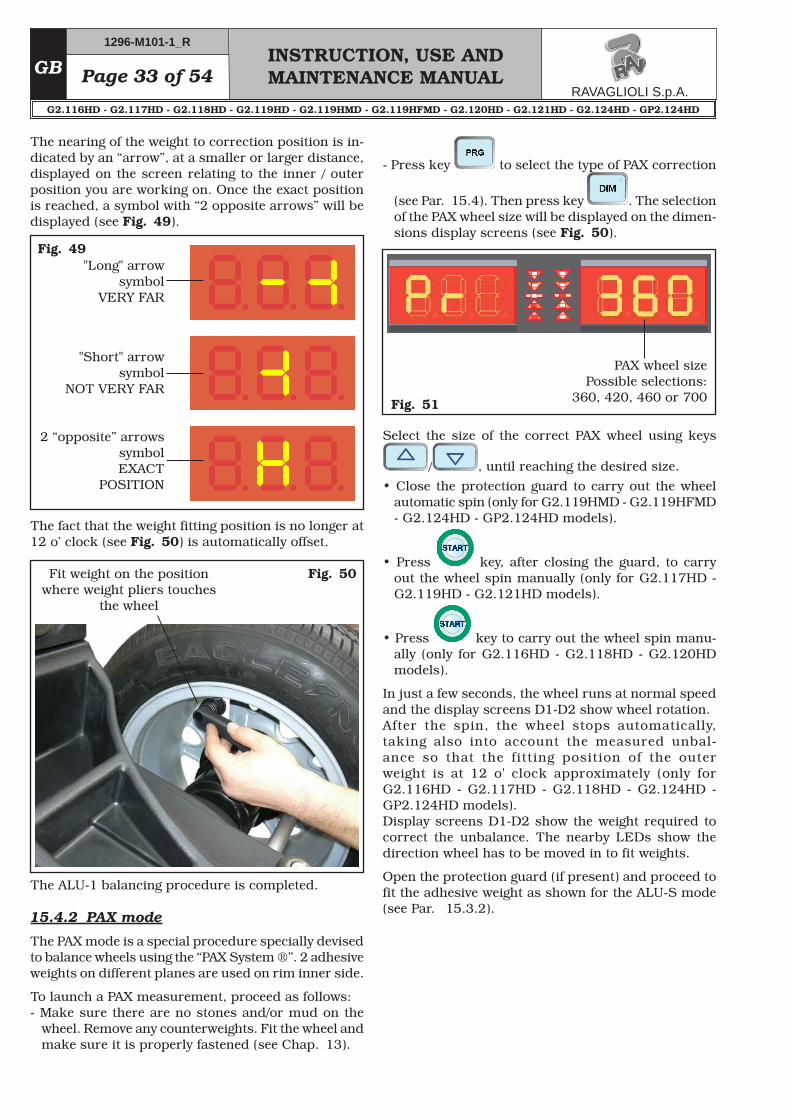
When the wheel balancer display shows the central
LED on ( ) the exact position for both sides has been reached. The fitting point has been found. Now the unbalance can be corrected by fitting the neces-sary weight.
Once the wheel has been correctly positioned, fit the weight indicated by the machine on both sides of the wheel. The program automatically indicates the best weights to be fitted and rounds these off according to their position.
15.4 Measuring the unbalance with auxil-iary programs
The available functions permit selecting the appropri-ate weight positions to be placed in positions different to the standard ones (dynamic unbalance).
The ALU programs measure rims by means of pre-set data in the wheel balancer. The measurements entered by the operator will there-fore be automatically corrected by the machine accord-ing to the selected program.
On the left side of the panel are indicated the possible selection modes. Select the desired function by means
of key and enter the measurements.
POSSIBLE SELECTABLE FUNCTIONSThe ALU-S 1 function permits balancing wheels with light alloy rims by fitting adhesive weights on the outer side and weight with clip on inner side of wheel (at 12 o’ clock).Enter the measurements (see Par. 15.1) and proceed as described in Par. 15.4.1 (the inner weight is with clip).
The ALU-S 2 function permits balancing wheels with light alloy rims by fitting two adhesive weights on the outer and inner sides of the rim (the inner weight is at 12 o’ clock).Enter the measurements (see Par. 15.1) and proceed as described in Par. 15.4.1 (the inner weight is adhe-sive).
15.3.4 Positioning the correction weights on the wheel
The weights must be positioned at the top part of the wheel, at 12 o’ clock, so that the unbalance will be at the bottom and the weight fitting point will be at the top.
When the wheel balancer display shows 2 led on at
the top or bottom ( or ) this means you are far away from the point where the counterweight is to be positioned.Wheel position is over 30° from the exact fitting point.
When the wheel balancer display shows 1 led on at
the top or bottom ( or ) this means you are not far from the point where the counterweight is to be positioned.Wheel position is within 30° from the exact fitting point.
The STATIC 1 function is a procedure that offsets wheel vibrations using a single adhesive weight on a single plane positioned exactly at 12 o’ clock.Enter the measurements (see Par. 15.1) and proceed as described in Par. 15.3.1 Dynamic balancing (only for wheel inner side).
INSTRUCTION, USE AND MAINTENANCE MANUALGB Page 31 of 54
The STATIC 2 function is a procedure that offsets wheel vibrations using a single weight with clip on a single plane positioned exactly at 12 o’ clock.Enter the measurements (see Par. 15.1) and proceed as described in Par. 15.3.1 Dynamic balancing (only for wheel inner side).
The ALU 1 function permits balancing wheels with light alloy rims by fitting adhesive weights on the outer and inner sides of the rim.Enter the measurements (see Par. 15.1) and proceed as described in Par. 15.4.1.
The ALU 2 function balances wheels with light alloy rims by fitting adhesive weights on the outside and inside of the rim. The position of the outer weight is not visible but hidden inside. Enter the measurements (see Par. 15.1) and proceed as for dynamic unbalance.
The ALU 3 function is a procedure that uses mixed weights to offset wheel unbalance: weight with clip on inner side of wheel, adhesive weight on outer side, not visible because inside the rim. Enter the measurements (see Par. 15.1) and proceed as for dynamic unbalance.
The ALU 4 function is a procedure that uses mixed weights to offset wheel unbalance: weight with clip on inner side of wheel, adhesive weight on outer side. Enter the measurements (see Par. 15.1) and proceed as for dynamic unbalance.
The PAX function is a procedure that permits balancing PAX wheels using adhesive weights at pre-set distances to offset wheel unbalance. Select the wheel type model and proceed as described in Par. 15.4.2.
For ALU-S, STATIC, ALU 1 and PAX functions, see relevant paragraphs.For all the other previously-indicated functions, wheel balancing will be done as indicated for dynamic balanc-ing (see Par. 15.3.1). The wheel balancer will automatically correct the measurements entered by the operator according to the selected function.
Page 32 of 54INSTRUCTION, USE AND MAINTENANCE MANUAL
GB
LEDs showing position-ing in correct weight fit-
ting point
Total outer weightTotal inner weight
To position wheel on the OUTER side, turn it in the direction shown by the LEDs, until reaching the correct position (see Par. 15.3.4). Once correct position has been reached, press the pedal brake to stop the wheel.Fit the adhesive weight on wheel outer side (in the ex-ample 20 g). The outer side weight must be positioned by hand on the vertical – at 12 o’clock (see Fig. 47).
Fig. 46
Fig. 47
Fig. 48 Fit the adhesive weight in the pliers of the gauge rod
To fit the adhesive weight on the INNER part of the wheel, turn it in the direction shown by the LEDs until the correct position is reached (see Par. 15.3.4).Take out the gauge rod and introduce the adhesive weight inside pliers as shown in Fig. 48 (only for G2.118HD, G2.119HD, G2.119HMD, G2.119HFMD, G2.120HD, G2.121HD, G2.124HD, GP2.124HD models).
15.4.1 ALU 1 procedure
ALU-1 balancing is a procedure that offsets the wheel vibrations using 2 weights on different planes. Adhesive weights are used on rim inner and outer edge, and is usually carried out on alloy rims.To launch a ALU-1 measurement, proceed as follows:- Make sure there are no stones and/or mud on the
wheel. Remove any counterweights. Fit the wheel and make sure it is properly fastened (see Chap. 13.0).
- Press key to select the type of ALU1 correction (see Par. 15.4).
Detect the wheel dimensions using the specific gauge rod (Par. 15.1.1) (only for G2.118HD, G2.119HD, G2.119HMD, G2.119HFMD, G2.124HD, GP2.124HD models).
• Close the protection guard to carry out the wheel automatic spin (only for G2.119HMD - G2.119HFMD - G2.124HD - GP2.124HD models).
• Press key, after closing the guard, to carry out the wheel spin manually (only for G2.117HD - G2.119HD - G2.121HD models).
• Press key to carry out the wheel spin manu-ally (only for G2.116HD - G2.118HD - G2.120HD models).
In just a few seconds, the wheel runs at normal speed and the display screens D1-D2 show wheel rotation.
After the spin, the wheel stops automatically, taking also into account the measured unbal-ance so that the fitting position of the outer weight is at 12 o' clock approximately (only for G2.116HD - G2.117HD - G2.118HD - G2.124HD - GP2.124HD models). Open the protection guard (if present).
Display screens D1-D2 show the weight required to correct the unbalance. The nearby LEDs show the direction wheel has to be moved in to fit weights (see Fig. 46).
INSTRUCTION, USE AND MAINTENANCE MANUALGB Page 33 of 54
The nearing of the weight to correction position is in-dicated by an “arrow”, at a smaller or larger distance, displayed on the screen relating to the inner / outer position you are working on. Once the exact position is reached, a symbol with “2 opposite arrows” will be displayed (see Fig. 49).
Fig. 49"Long" arrow
symbol VERY FAR
"Short" arrow symbol
NOT VERY FAR
2 “opposite” arrows symbol EXACT
POSITION
The fact that the weight fitting position is no longer at 12 o’ clock (see Fig. 50) is automatically offset.
Fig. 50Fit weight on the position where weight pliers touches
the wheel
Fig. 51
PAX wheel size Possible selections:
360, 420, 460 or 700
The ALU-1 balancing procedure is completed.
15.4.2 PAX mode
The PAX mode is a special procedure specially devised to balance wheels using the “PAX System ®”. 2 adhesive weights on different planes are used on rim inner side.
To launch a PAX measurement, proceed as follows:- Make sure there are no stones and/or mud on the
wheel. Remove any counterweights. Fit the wheel and make sure it is properly fastened (see Chap. 13).
- Press key to select the type of PAX correction
(see Par. 15.4). Then press key . The selection of the PAX wheel size will be displayed on the dimen-sions display screens (see Fig. 50).
• Press key, after closing the guard, to carry out the wheel spin manually (only for G2.117HD - G2.119HD - G2.121HD models).
• Press key to carry out the wheel spin manu-ally (only for G2.116HD - G2.118HD - G2.120HD models).
In just a few seconds, the wheel runs at normal speed and the display screens D1-D2 show wheel rotation.After the spin, the wheel stops automatically, taking also into account the measured unbal-ance so that the fitting position of the outer weight is at 12 o' clock approximately (only for G2.116HD - G2.117HD - G2.118HD - G2.124HD - GP2.124HD models). Display screens D1-D2 show the weight required to correct the unbalance. The nearby LEDs show the direction wheel has to be moved in to fit weights.
Open the protection guard (if present) and proceed to fit the adhesive weight as shown for the ALU-S mode (see Par. 15.3.2).
Page 34 of 54INSTRUCTION, USE AND MAINTENANCE MANUAL
GB
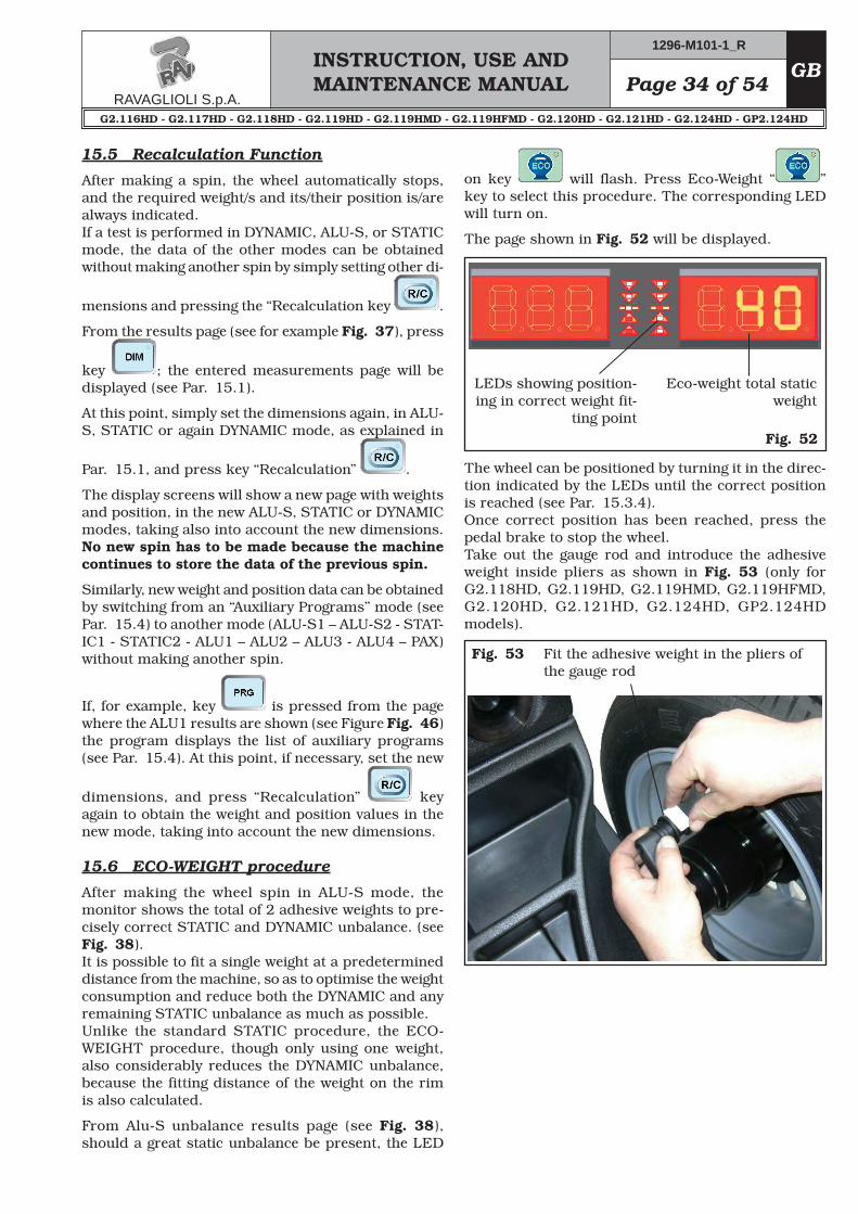
Fig. 52
Eco-weight total static weight
LEDs showing position-ing in correct weight fit-
ting point
Fig. 53 Fit the adhesive weight in the pliers of the gauge rod
15.5 Recalculation Function
After making a spin, the wheel automatically stops, and the required weight/s and its/their position is/are always indicated.If a test is performed in DYNAMIC, ALU-S, or STATIC mode, the data of the other modes can be obtained without making another spin by simply setting other di-
mensions and pressing the “Recalculation key .
From the results page (see for example Fig. 37), press
key ; the entered measurements page will be displayed (see Par. 15.1).
At this point, simply set the dimensions again, in ALU-S, STATIC or again DYNAMIC mode, as explained in
Par. 15.1, and press key “Recalculation” .
The display screens will show a new page with weights and position, in the new ALU-S, STATIC or DYNAMIC modes, taking also into account the new dimensions.No new spin has to be made because the machine continues to store the data of the previous spin.
Similarly, new weight and position data can be obtained by switching from an “Auxiliary Programs” mode (see Par. 15.4) to another mode (ALU-S1 – ALU-S2 - STAT-IC1 - STATIC2 - ALU1 – ALU2 – ALU3 - ALU4 – PAX) without making another spin.
If, for example, key is pressed from the page where the ALU1 results are shown (see Figure Fig. 46) the program displays the list of auxiliary programs (see Par. 15.4). At this point, if necessary, set the new
dimensions, and press “Recalculation” key again to obtain the weight and position values in the new mode, taking into account the new dimensions.
15.6 ECO-WEIGHT procedure
After making the wheel spin in ALU-S mode, the monitor shows the total of 2 adhesive weights to pre-cisely correct STATIC and DYNAMIC unbalance. (see Fig. 38).It is possible to fit a single weight at a predetermined distance from the machine, so as to optimise the weight consumption and reduce both the DYNAMIC and any remaining STATIC unbalance as much as possible.Unlike the standard STATIC procedure, the ECO-WEIGHT procedure, though only using one weight, also considerably reduces the DYNAMIC unbalance, because the fitting distance of the weight on the rim is also calculated.
From Alu-S unbalance results page (see Fig. 38), should a great static unbalance be present, the LED
on key will flash. Press Eco-Weight “ ” key to select this procedure. The corresponding LED will turn on.
The wheel can be positioned by turning it in the direc-tion indicated by the LEDs until the correct position is reached (see Par. 15.3.4). Once correct position has been reached, press the pedal brake to stop the wheel.Take out the gauge rod and introduce the adhesive weight inside pliers as shown in Fig. 53 (only for G2.118HD, G2.119HD, G2.119HMD, G2.119HFMD, G2.120HD, G2.121HD, G2.124HD, GP2.124HD models).
INSTRUCTION, USE AND MAINTENANCE MANUALGB Page 35 of 54
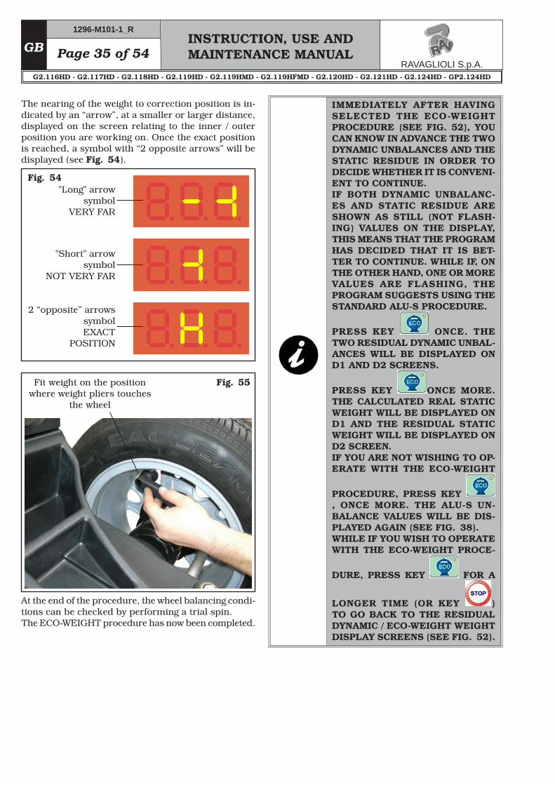
The nearing of the weight to correction position is in-dicated by an “arrow”, at a smaller or larger distance, displayed on the screen relating to the inner / outer position you are working on. Once the exact position is reached, a symbol with “2 opposite arrows” will be displayed (see Fig. 54).
"Long" arrow symbol
VERY FAR
"Short" arrow symbol
NOT VERY FAR
2 “opposite” arrows symbol EXACT
POSITION
Fig. 55Fit weight on the position where weight pliers touches
the wheel
At the end of the procedure, the wheel balancing condi-tions can be checked by performing a trial spin.The ECO-WEIGHT procedure has now been completed.
IMMEDIATELY AFTER HAVING SELECTED THE ECO-WEIGHT PROCEDURE (SEE FIG. 52), YOU CAN KNOW IN ADVANCE THE TWO DYNAMIC UNBALANCES AND THE STATIC RESIDUE IN ORDER TO DECIDE WHETHER IT IS CONVENI-ENT TO CONTINUE.IF BOTH DYNAMIC UNBALANC-ES AND STATIC RESIDUE ARE SHOWN AS STILL (NOT FLASH-ING) VALUES ON THE DISPLAY, THIS MEANS THAT THE PROGRAM HAS DECIDED THAT IT IS BET-TER TO CONTINUE. WHILE IF, ON THE OTHER HAND, ONE OR MORE VALUES ARE FLASHING, THE PROGRAM SUGGESTS USING THE STANDARD ALU-S PROCEDURE.
PRESS KEY ONCE. THE TWO RESIDUAL DYNAMIC UNBAL-ANCES WILL BE DISPLAYED ON D1 AND D2 SCREENS.
PRESS KEY ONCE MORE. THE CALCULATED REAL STATIC WEIGHT WILL BE DISPLAYED ON D1 AND THE RESIDUAL STATIC WEIGHT WILL BE DISPLAYED ON D2 SCREEN. IF YOU ARE NOT WISHING TO OP-ERATE WITH THE ECO-WEIGHT
PROCEDURE, PRESS KEY , ONCE MORE. THE ALU-S UN-BALANCE VALUES WILL BE DIS-PLAYED AGAIN (SEE FIG. 38). WHILE IF YOU WISH TO OPERATE WITH THE ECO-WEIGHT PROCE-
DURE, PRESS KEY FOR A
LONGER TIME (OR KEY ) TO GO BACK TO THE RESIDUAL DYNAMIC / ECO-WEIGHT WEIGHT DISPLAY SCREENS (SEE FIG. 52).
Page 36 of 54INSTRUCTION, USE AND MAINTENANCE MANUAL
GB
16.0 WHEEL BALANCING IN MOTOR-BIKE MODE
By enabling the “motorbike wheel balancing” function (see Par. 21.2), the wheel balancers can also balance motorbike wheels.
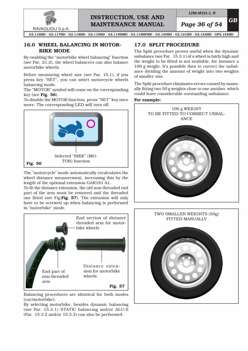
Before measuring wheel size (see Par. 15.1), if you press key ”SET”, you can select motorcycle wheels balancing mode.The “MOTOR” symbol will come on the corresponding key (see Fig. 56). To disable the MOTOR function, press ”SET” key once more. The corresponding LED will turn off.
Selected “BIKE” (MO-TOR) function
The "motorcycle" mode automatically recalculates the wheel distance measurement, increasing this by the length of the optional extension GAR181 A1.To fit the distance extension, the old non-threaded end part of the arm must be removed and the threaded one fitted (see Fig.Fig. 57). The extension will only have to be screwed up when balancing is performed in "motorbike" mode.
End section of distance threaded arm for motor-bike wheels
End part of non-threaded arm
Distance exten-sion for motorbike wheels
Balancing procedures are identical for both modes (car/motorbike).By selecting motorbike, besides dynamic balancing (see Par. 15.3.1) STATIC balancing and/or ALU-S (Par. 15.3.2 and/or 15.3.3) can also be performed.
17.0 SPLIT PROCEDUREThe Split procedure proves useful when the dynamic unbalance (see Par. 15.3.1) of a wheel is fairly high and the weight to be fitted is not available, for instance a 100 g weight. It's possible then to correct the unbal-ance dividing the amount of weight into two weights of smaller size.
The Split procedure eliminates errors caused by manu-ally fitting two 50 g weights close to one another, which could leave considerable outstanding unbalance.For example:
INSTRUCTION, USE AND MAINTENANCE MANUALGB Page 37 of 54
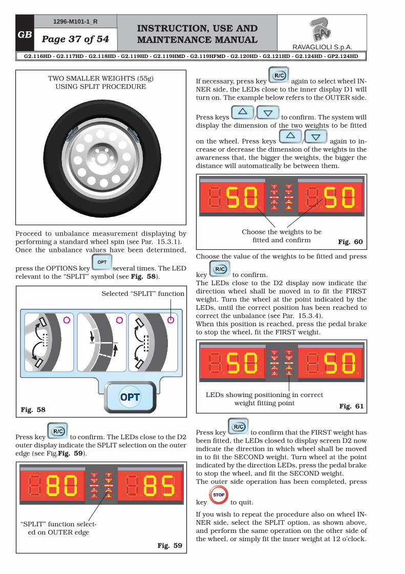
TWO SMALLER WEIGHTS (55g)USING SPLIT PROCEDURE
Proceed to unbalance measurement displaying by performing a standard wheel spin (see Par. 15.3.1).Once the unbalance values have been determined,
press the OPTIONS key several times. The LED relevant to the “SPLIT” symbol (see Fig. 58).
Fig. 58
Selected “SPLIT” function
Press key to confirm. The LEDs close to the D2 outer display indicate the SPLIT selection on the outer edge (see Fig.Fig. 59).
Fig. 59
“SPLIT” function select-ed on OUTER edge
If necessary, press key again to select wheel IN-NER side, the LEDs close to the inner display D1 will turn on. The example below refers to the OUTER side.
Press keys / to confirm. The system will display the dimension of the two weights to be fitted
on the wheel. Press keys / again to in-crease or decrease the dimension of the weights in the awareness that, the bigger the weights, the bigger the distance will automatically be between them.
Fig. 60Choose the weights to be
fitted and confirm
Choose the value of the weights to be fitted and press
key to confirm.The LEDs close to the D2 display now indicate the direction wheel shall be moved in to fit the FIRST weight. Turn the wheel at the point indicated by the LEDs, until the correct position has been reached to correct the unbalance (see Par. 15.3.4).When this position is reached, press the pedal brake to stop the wheel, fit the FIRST weight.
Fig. 61
LEDs showing positioning in correct weight fitting point
Press key to confirm that the FIRST weight has been fitted, the LEDs closed to display screen D2 now indicate the direction in which wheel shall be moved in to fit the SECOND weight. Turn wheel at the point indicated by the direction LEDs, press the pedal brake to stop the wheel, and fit the SECOND weight.The outer side operation has been completed, press
key to quit.
If you wish to repeat the procedure also on wheel IN-NER side, select the SPLIT option, as shown above, and perform the same operation on the other side of the wheel, or simply fit the inner weight at 12 o’clock.
Page 38 of 54INSTRUCTION, USE AND MAINTENANCE MANUAL
GB
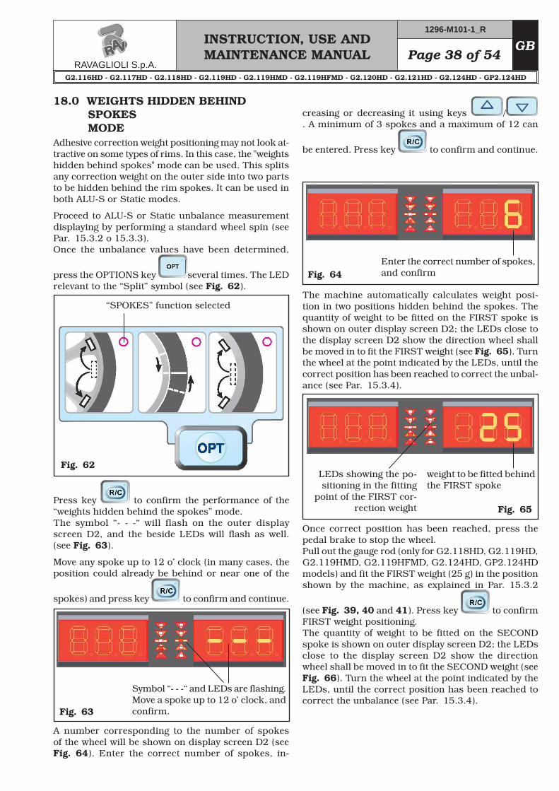
18.0 WEIGHTS HIDDEN BEHIND SPOKES MODE
Adhesive correction weight positioning may not look at-tractive on some types of rims. In this case, the "weights hidden behind spokes" mode can be used. This splits any correction weight on the outer side into two parts to be hidden behind the rim spokes. It can be used in both ALU-S or Static modes.
Proceed to ALU-S or Static unbalance measurement displaying by performing a standard wheel spin (see Par. 15.3.2 o 15.3.3).Once the unbalance values have been determined,
press the OPTIONS key several times. The LED relevant to the “Split” symbol (see Fig. 62).
Fig. 62
“SPOKES” function selected
Press key to confirm the performance of the “weights hidden behind the spokes” mode.The symbol “- - -“ will flash on the outer display screen D2, and the beside LEDs will flash as well. (see Fig. 63).
Move any spoke up to 12 o’ clock (in many cases, the position could already be behind or near one of the
spokes) and press key to confirm and continue.
Fig. 63
Symbol “- - -“ and LEDs are flashing.Move a spoke up to 12 o’ clock, and confirm.
A number corresponding to the number of spokes of the wheel will be shown on display screen D2 (see Fig. 64). Enter the correct number of spokes, in-
creasing or decreasing it using keys /. A minimum of 3 spokes and a maximum of 12 can
be entered. Press key to confirm and continue.
Enter the correct number of spokes, and confirm
The machine automatically calculates weight posi-tion in two positions hidden behind the spokes. The quantity of weight to be fitted on the FIRST spoke is shown on outer display screen D2; the LEDs close to the display screen D2 show the direction wheel shall be moved in to fit the FIRST weight (see Fig. 65). Turn the wheel at the point indicated by the LEDs, until the correct position has been reached to correct the unbal-ance (see Par. 15.3.4).
Once correct position has been reached, press the pedal brake to stop the wheel.Pull out the gauge rod (only for G2.118HD, G2.119HD, G2.119HMD, G2.119HFMD, G2.124HD, GP2.124HD models) and fit the FIRST weight (25 g) in the position shown by the machine, as explained in Par. 15.3.2
(see Fig. 39, 40 and 41). Press key to confirm FIRST weight positioning.The quantity of weight to be fitted on the SECOND spoke is shown on outer display screen D2; the LEDs close to the display screen D2 show the direction wheel shall be moved in to fit the SECOND weight (see Fig. 66). Turn the wheel at the point indicated by the LEDs, until the correct position has been reached to correct the unbalance (see Par. 15.3.4).
INSTRUCTION, USE AND MAINTENANCE MANUALGB Page 39 of 54
Fig. 66
weight to be fitted behind the SECOND spoke
LEDs showing the po-sitioning in the fitting point of the SECOND
correction weight
IF NECESSARY, YOU CAN PRESS
KEY TO GO BACK STEP-BY-STEP THROUGH THE DIFFERENT STAGES OF THIS PROCEDURE.
19.0 MATCHING PROCEDURE (Rim - Tyre Optimisation)
The Matching procedure offsets strong unbalance, reducing the weight quantity to be fitted on the wheel to achieve balancing. This procedure permits reducing unbalance as much as possible by offsetting the tyre unbalance with that of the rim.
Proceed to dynamic unbalance measurement dis-playing by performing a standard wheel spin (see Par. 15.3.2).
THE MATCHING PROCEDURE CAN BE CARRIED OUT ONLY IF THE STATIC UNBALANCE IS > 30 G.
Once the unbalance values have been determined,
press the OPTIONS key several times. The LED relevant to the “MATCHING” symbol (see Fig. 67).
Fig. 67
“MATCHING” function selected
Press key to confirm “MATCHING” mode per-formance.The “P 1” symbol flashes on outer D2 display to indi-cate that the 1st step of the procedure shall be carried out (see Fig. 68).
STEP 1. Make a reference mark, using chalk for in-stance, of the position of the rim and tyre, remaining in line with the arrow on the flange, so as to be able to fit the rim back on in the same position on the
machine. Press key to confirm that step 1 has been completed.
Once correct position has been reached, press the pedal brake to stop the wheel.Take out the gauge rod (only for G2.118HD, G2.119HD, G2.119HMD, G2.119HFMD, G2.124HD, GP2.124HD models) and fit the SECOND weight (30 g) in the po-sition indicated by the machine, as done for the first weight.
Press key to confirm positioning also of the SECOND weight.
The display screens D1 and D2 show again the initial unbalance situation before performing the “weights hidden behind spokes” procedure.
Perform another test spin. The “weights hidden behind spokes” procedure is completed.
Page 40 of 54INSTRUCTION, USE AND MAINTENANCE MANUAL
GB
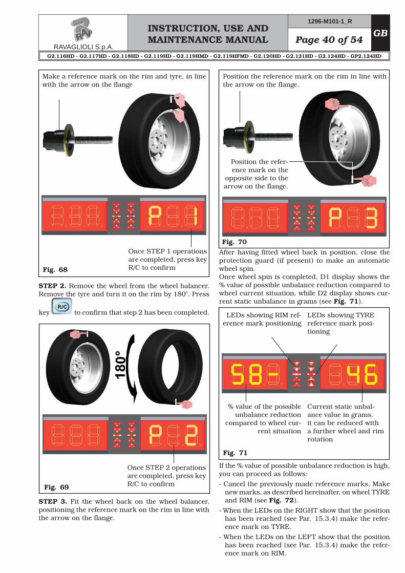
Fig. 68
Once STEP 1 operations are completed, press key R/C to confirm
Make a reference mark on the rim and tyre, in line with the arrow on the flange
STEP 2. Remove the wheel from the wheel balancer. Remove the tyre and turn it on the rim by 180°. Press
key to confirm that step 2 has been completed.
Fig. 69
Once STEP 2 operations are completed, press key R/C to confirm
STEP 3. Fit the wheel back on the wheel balancer, positioning the reference mark on the rim in line with the arrow on the flange.
Fig. 70
Position the reference mark on the rim in line with the arrow on the flange.
Position the refer-ence mark on the
opposite side to the arrow on the flange.
After having fitted wheel back in position, close the protection guard (if present) to make an automatic wheel spin.Once wheel spin is completed, D1 display shows the % value of possible unbalance reduction compared to wheel current situation, while D2 display shows cur-rent static unbalance in grams (see Fig. 71).
Fig. 71
LEDs showing RIM ref-erence mark positioning
LEDs showing TYRE reference mark posi-tioning
% value of the possible unbalance reduction
compared to wheel cur-rent situation
Current static unbal-ance value in grams. it can be reduced with a further wheel and rim rotation
If the % value of possible unbalance reduction is high, you can proceed as follows:- Cancel the previously made reference marks. Make
new marks, as described hereinafter, on wheel TYRE and RIM (see Fig. 72).
- When the LEDs on the RIGHT show that the position has been reached (see Par. 15.3.4) make the refer-ence mark on TYRE.
- When the LEDs on the LEFT show that the position has been reached (see Par. 15.3.4) make the refer-ence mark on RIM.
INSTRUCTION, USE AND MAINTENANCE MANUALGB Page 41 of 54
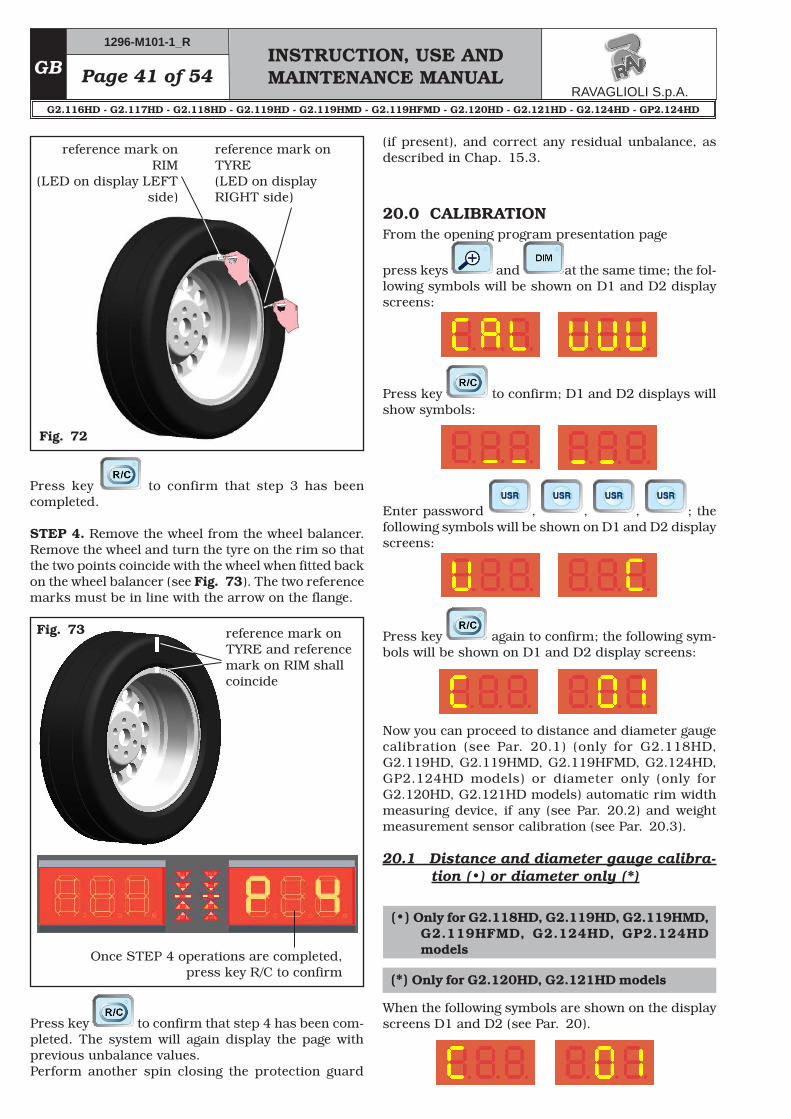
Fig. 72
reference mark on RIM
(LED on display LEFT side)
reference mark on TYRE (LED on display RIGHT side)
Press key to confirm that step 3 has been completed.
STEP 4. Remove the wheel from the wheel balancer. Remove the wheel and turn the tyre on the rim so that the two points coincide with the wheel when fitted back on the wheel balancer (see Fig. 73). The two reference marks must be in line with the arrow on the flange.
Fig. 73 reference mark on TYRE and reference mark on RIM shall coincide
Once STEP 4 operations are completed, press key R/C to confirm
Press key to confirm that step 4 has been com-pleted. The system will again display the page with previous unbalance values.Perform another spin closing the protection guard
(if present), and correct any residual unbalance, as described in Chap. 15.3.
20.0 CALIBRATIONFrom the opening program presentation page
press keys and at the same time; the fol-lowing symbols will be shown on D1 and D2 display screens:
Press key to confirm; D1 and D2 displays will show symbols:
Enter password , , , ; the following symbols will be shown on D1 and D2 display screens:
Press key again to confirm; the following sym-bols will be shown on D1 and D2 display screens:
When the following symbols are shown on the display screens D1 and D2 (see Par. 20).
(•) Only for G2.118HD, G2.119HD, G2.119HMD, G2.119HFMD, G2.124HD, GP2.124HD models
Now you can proceed to distance and diameter gauge calibration (see Par. 20.1) (only for G2.118HD, G2.119HD, G2.119HMD, G2.119HFMD, G2.124HD, GP2.124HD models) or diameter only (only for G2.120HD, G2.121HD models) automatic rim width measuring device, if any (see Par. 20.2) and weight measurement sensor calibration (see Par. 20.3).
20.1 Distance and diameter gauge calibra-tion (•) or diameter only (*)
(*) Only for G2.120HD, G2.121HD models
Page 42 of 54INSTRUCTION, USE AND MAINTENANCE MANUAL
GB
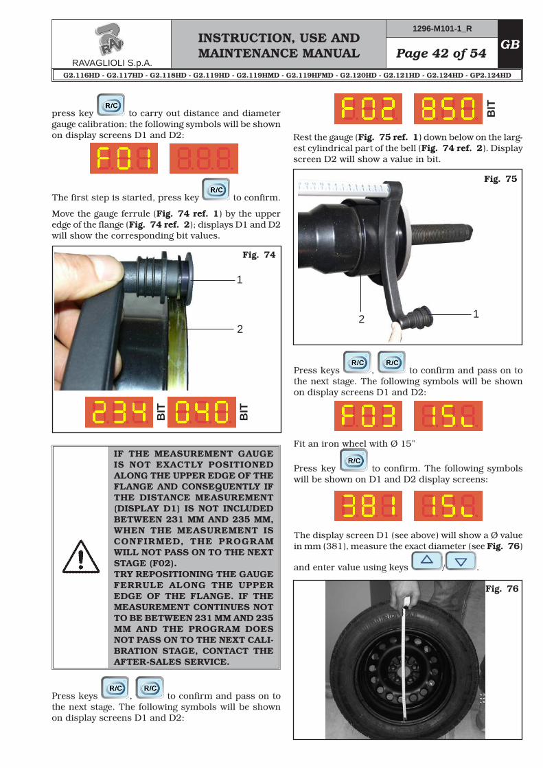
The first step is started, press key to confirm.
Move the gauge ferrule (Fig. 74 ref. 1) by the upper edge of the flange (Fig. 74 ref. 2); displays D1 and D2 will show the corresponding bit values.
Fig. 74
2
BIT
BIT
IF THE MEASUREMENT GAUGE IS NOT EXACTLY POSITIONED ALONG THE UPPER EDGE OF THE FLANGE AND CONSEQUENTLY IF THE DISTANCE MEASUREMENT (DISPLAY D1) IS NOT INCLUDED BETWEEN 231 MM AND 235 MM, WHEN THE MEASUREMENT IS CONFIRMED, THE PROGRAM WILL NOT PASS ON TO THE NEXT STAGE (F02).TRY REPOSITIONING THE GAUGE FERRULE ALONG THE UPPER EDGE OF THE FLANGE. IF THE MEASUREMENT CONTINUES NOT TO BE BETWEEN 231 MM AND 235 MM AND THE PROGRAM DOES NOT PASS ON TO THE NEXT CALI-BRATION STAGE, CONTACT THE AFTER-SALES SERVICE.
Press keys , to confirm and pass on to the next stage. The following symbols will be shown on display screens D1 and D2:
BIT
Fig. 75
Rest the gauge (Fig. 75 ref. 1) down below on the larg-est cylindrical part of the bell (Fig. 74 ref. 2). Display screen D2 will show a value in bit.
Press keys , to confirm and pass on to the next stage. The following symbols will be shown on display screens D1 and D2:
Fit an iron wheel with Ø 15”
Press key to confirm. The following symbols will be shown on D1 and D2 display screens:
The display screen D1 (see above) will show a Ø value in mm (381), measure the exact diameter (see Fig. 76)
and enter value using keys / .
Fig. 76
1
12
press key to carry out distance and diameter gauge calibration; the following symbols will be shown on display screens D1 and D2:
INSTRUCTION, USE AND MAINTENANCE MANUALGB Page 43 of 54
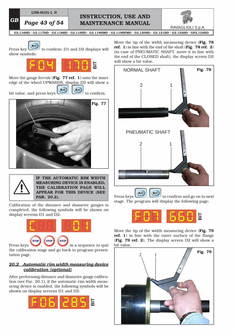
Press key to confirm; D1 and D2 displays will show symbols:
BIT
Move the gauge ferrule (Fig. 77 ref. 1) onto the inner edge of the wheel UPWARDS, display D2 will show a
bit value, and press keys , to confirm.
Fig. 771
IF THE AUTOMATIC RIM WIDTH MEASURING DEVICE IS ENABLED, THE CALIBRATION PAGE WILL APPEAR FOR THIS DEVICE (SEE PAR. 20.2).
Calibration of the distance and diameter gauges is completed, the following symbols will be shown on display screens D1 and D2:
Press keys , , in a sequence to quit the calibration stage and go back to program presen-tation page.
20.2 Automatic rim width measuring device calibration (optional)
After performing distance and diameter gauge calibra-tion (see Par. 20.1), if the automatic rim width meas-uring device is enabled, the following symbols will be shown on display screens D1 and D2:
BIT
Move the tip of the width measuring device (Fig. 78 ref. 1) in line with the end of the shaft (Fig. 78 ref. 2) (in case of PNEUMATIC SHAFT, move it in line with the end of the CLOSED shaft), the display screen D2 will show a bit value.
Fig. 78NORMAL SHAFT
PNEUMATIC SHAFT
2
Press keys , to confirm and go on to next stage. The program will display the following page:B
IT
Move the tip of the width measuring device (Fig. 79 ref. 1) in line with the outer surface of the flange (Fig. 79 ref. 2). The display screen D2 will show a bit value.
Page 44 of 54INSTRUCTION, USE AND MAINTENANCE MANUAL
GB
Press keys , to confirm.Calibration of the distance and diameter gauges is completed, the following symbols will be shown on display screens D1 and D2:
Press keys , , in a sequence to quit the calibration stage and go back to program presen-tation page.
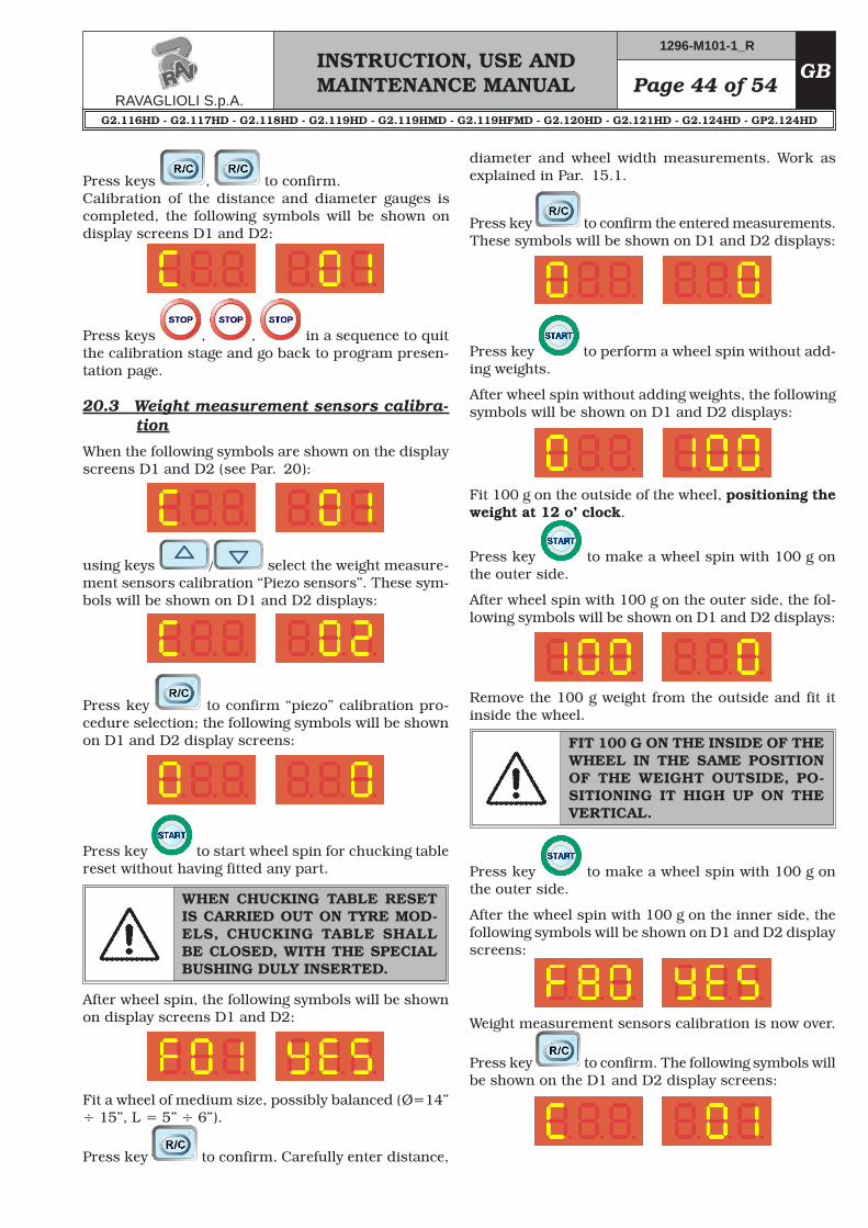
20.3 Weight measurement sensors calibra-tion
When the following symbols are shown on the display screens D1 and D2 (see Par. 20):
using keys / select the weight measure-ment sensors calibration “Piezo sensors”. These sym-bols will be shown on D1 and D2 displays:
Press key to confirm “piezo” calibration pro-cedure selection; the following symbols will be shown on D1 and D2 display screens:
Press key to start wheel spin for chucking table reset without having fitted any part.
WHEN CHUCKING TABLE RESET IS CARRIED OUT ON TYRE MOD-ELS, CHUCKING TABLE SHALL BE CLOSED, WITH THE SPECIAL BUSHING DULY INSERTED.
After wheel spin, the following symbols will be shown on display screens D1 and D2:
Fit a wheel of medium size, possibly balanced (Ø=14” ÷ 15”, L = 5” ÷ 6”).
Press key to confirm. Carefully enter distance,
Press key to perform a wheel spin without add-ing weights.
After wheel spin without adding weights, the following symbols will be shown on D1 and D2 displays:
Fit 100 g on the outside of the wheel, positioning the weight at 12 o’ clock.
Press key to make a wheel spin with 100 g on the outer side.
After wheel spin with 100 g on the outer side, the fol-lowing symbols will be shown on D1 and D2 displays:
Remove the 100 g weight from the outside and fit it inside the wheel.
FIT 100 G ON THE INSIDE OF THE WHEEL IN THE SAME POSITION OF THE WEIGHT OUTSIDE, PO-SITIONING IT HIGH UP ON THE VERTICAL.
Press key to make a wheel spin with 100 g on the outer side.
After the wheel spin with 100 g on the inner side, the following symbols will be shown on D1 and D2 display screens:
Weight measurement sensors calibration is now over.
Press key to confirm. The following symbols will be shown on the D1 and D2 display screens:
diameter and wheel width measurements. Work as explained in Par. 15.1.
Press key to confirm the entered measurements. These symbols will be shown on D1 and D2 displays:
INSTRUCTION, USE AND MAINTENANCE MANUALGB Page 45 of 54
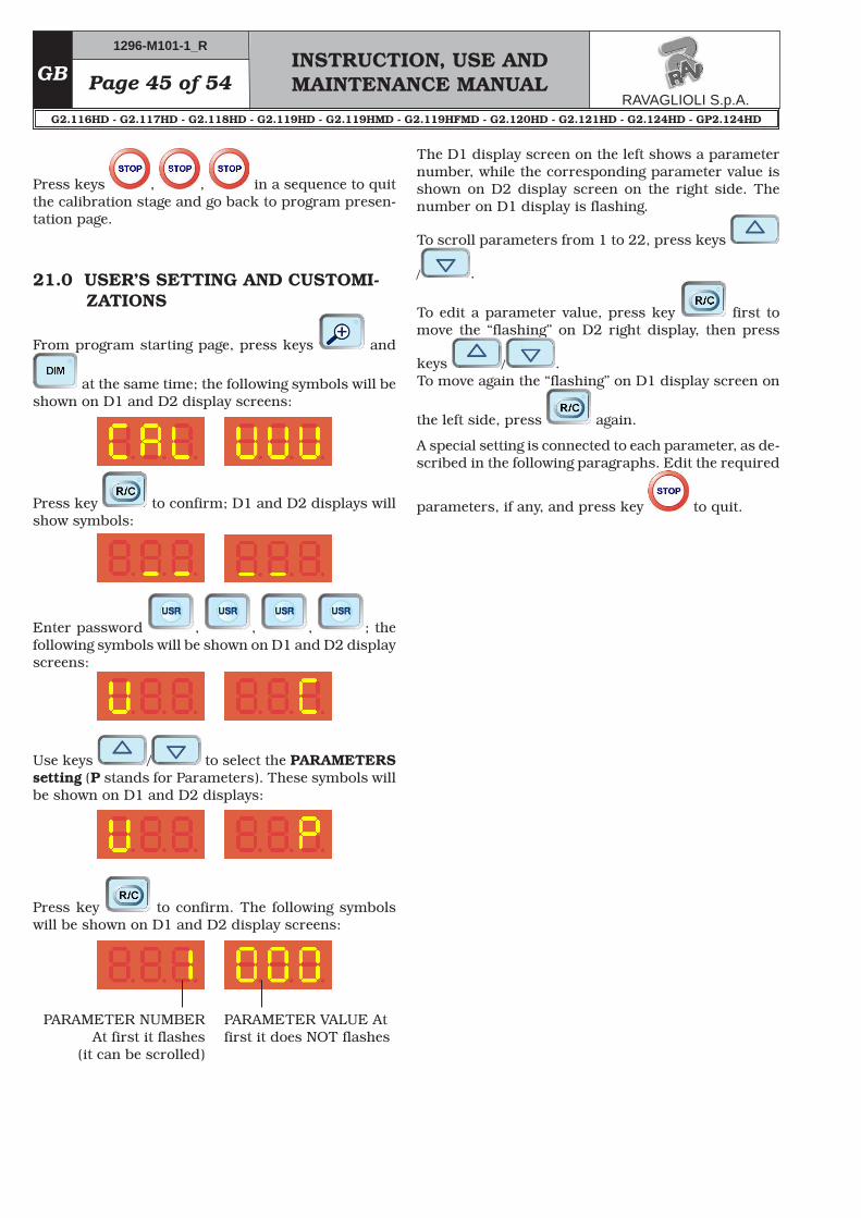
Press keys , , in a sequence to quit the calibration stage and go back to program presen-tation page.
21.0 USER’S SETTING AND CUSTOMI-ZATIONS
From program starting page, press keys and
at the same time; the following symbols will be shown on D1 and D2 display screens:
Press key to confirm; D1 and D2 displays will show symbols:
Enter password , , , ; the following symbols will be shown on D1 and D2 display screens:
Use keys / to select the PARAMETERS setting (P stands for Parameters). These symbols will be shown on D1 and D2 displays:
Press key to confirm. The following symbols will be shown on D1 and D2 display screens:
PARAMETER NUMBER At first it flashes
(it can be scrolled)
PARAMETER VALUE At first it does NOT flashes
The D1 display screen on the left shows a parameter number, while the corresponding parameter value is shown on D2 display screen on the right side. The number on D1 display is flashing.
To scroll parameters from 1 to 22, press keys
/ .
To edit a parameter value, press key first to move the “flashing” on D2 right display, then press
keys / . To move again the “flashing” on D1 display screen on
the left side, press again.
A special setting is connected to each parameter, as de-scribed in the following paragraphs. Edit the required
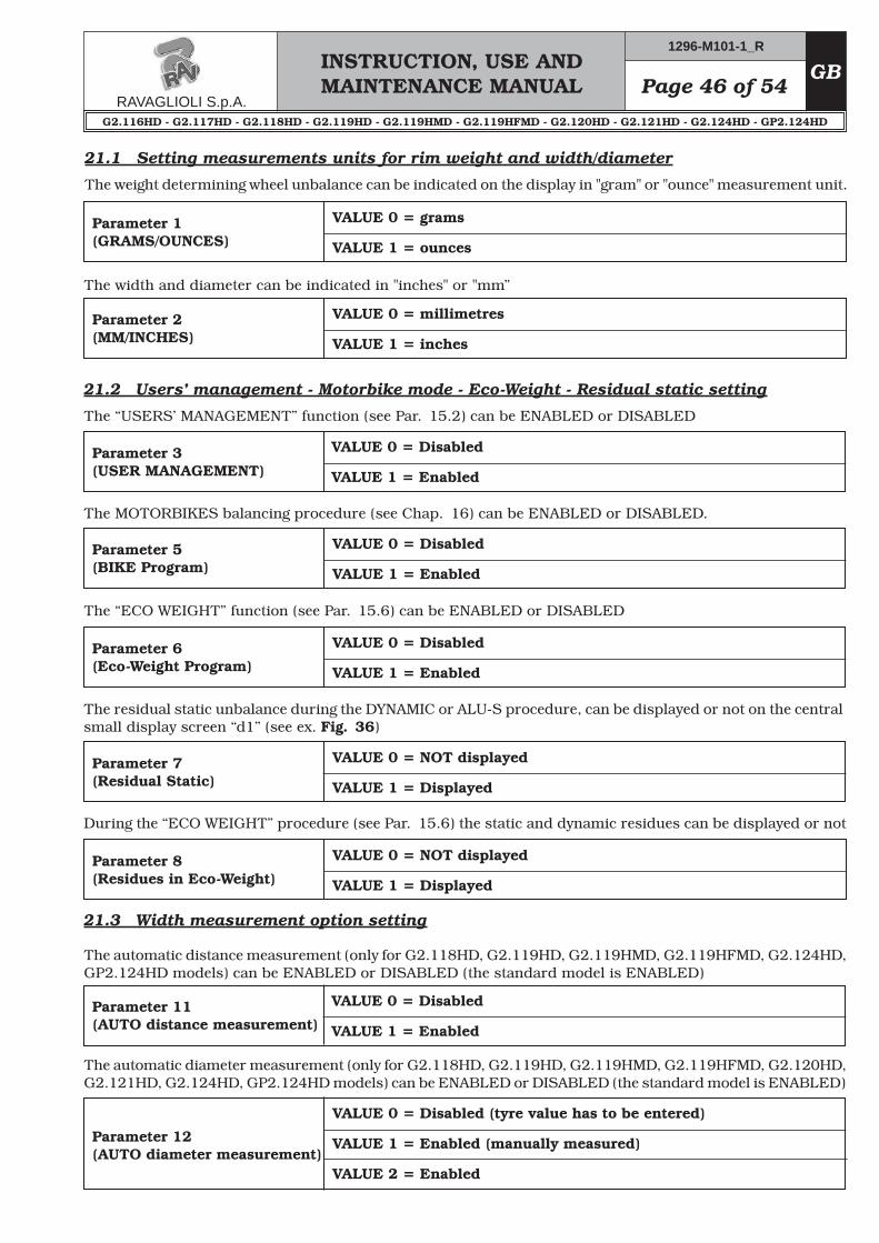
The “USERS’ MANAGEMENT” function (see Par. 15.2) can be ENABLED or DISABLED
Parameter 3(USER MANAGEMENT)
VALUE 0 = Disabled
VALUE 1 = Enabled
The MOTORBIKES balancing procedure (see Chap. 16) can be ENABLED or DISABLED.
Parameter 5(BIKE Program)
VALUE 0 = Disabled
VALUE 1 = Enabled
The “ECO WEIGHT” function (see Par. 15.6) can be ENABLED or DISABLED
Parameter 6(Eco-Weight Program)
VALUE 0 = Disabled
VALUE 1 = Enabled
The residual static unbalance during the DYNAMIC or ALU-S procedure, can be displayed or not on the central small display screen “d1” (see ex. Fig. 36)
Parameter 7(Residual Static)
VALUE 0 = NOT displayed
VALUE 1 = Displayed
During the “ECO WEIGHT” procedure (see Par. 15.6) the static and dynamic residues can be displayed or not
The automatic distance measurement (only for G2.118HD, G2.119HD, G2.119HMD, G2.119HFMD, G2.124HD, GP2.124HD models) can be ENABLED or DISABLED (the standard model is ENABLED)
The automatic diameter measurement (only for G2.118HD, G2.119HD, G2.119HMD, G2.119HFMD, G2.120HD, G2.121HD, G2.124HD, GP2.124HD models) can be ENABLED or DISABLED (the standard model is ENABLED)
INSTRUCTION, USE AND MAINTENANCE MANUALGB Page 47 of 54
DISTANCE AND DIAMETER AUTOMATIC METER IS ALWAYS PART OF THE STANDARD OUTFIT, SO IT HAS TO BE DISABLED IN PARAMETERS 11 AND 12 ONLY IF IT IS FAULTY.
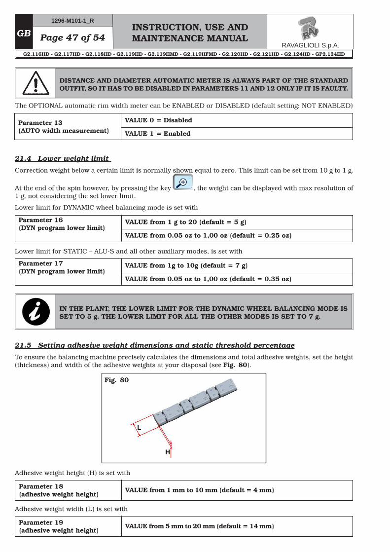
21.5 Setting adhesive weight dimensions and static threshold percentage
To ensure the balancing machine precisely calculates the dimensions and total adhesive weights, set the height (thickness) and width of the adhesive weights at your disposal (see Fig. 80).
IN THE PLANT, THE LOWER LIMIT FOR THE DYNAMIC WHEEL BALANCING MODE IS SET TO 5 g. THE LOWER LIMIT FOR ALL THE OTHER MODES IS SET TO 7 g.
Fig. 80
The OPTIONAL automatic rim width meter can be ENABLED or DISABLED (default setting: NOT ENABLED)
Parameter 13(AUTO width measurement)
VALUE 0 = Disabled
VALUE 1 = Enabled
21.4 Lower weight limit
Correction weight below a certain limit is normally shown equal to zero. This limit can be set from 10 g to 1 g.
At the end of the spin however, by pressing the key , the weight can be displayed with max resolution of 1 g, not considering the set lower limit.
Lower limit for DYNAMIC wheel balancing mode is set with
Parameter 16(DYN program lower limit)
VALUE from 1 g to 20 (default = 5 g)
VALUE from 0.05 oz to 1,00 oz (default = 0.25 oz)
Lower limit for STATIC – ALU-S and all other auxiliary modes, is set with
Page 48 of 54INSTRUCTION, USE AND MAINTENANCE MANUAL
GB
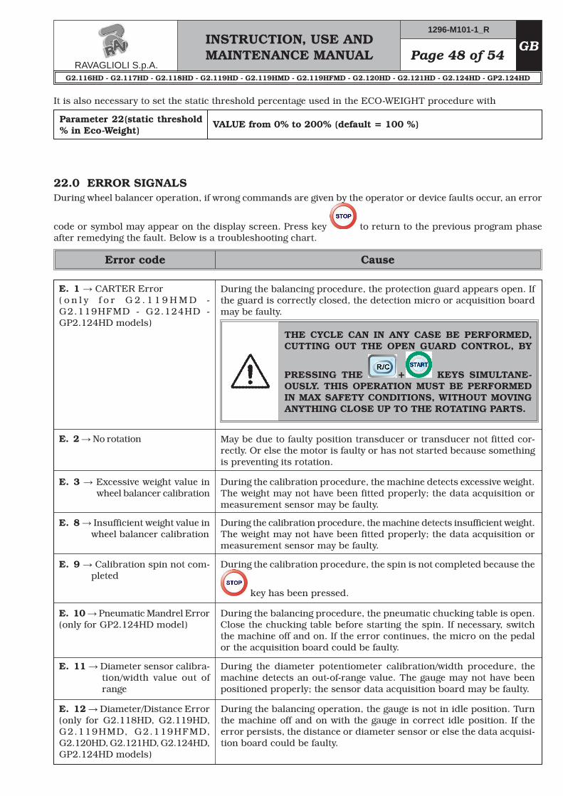
22.0 ERROR SIGNALSDuring wheel balancer operation, if wrong commands are given by the operator or device faults occur, an error
code or symbol may appear on the display screen. Press key to return to the previous program phase after remedying the fault. Below is a troubleshooting chart.
Error code Cause
During the balancing procedure, the protection guard appears open. If the guard is correctly closed, the detection micro or acquisition board may be faulty.
THE CYCLE CAN IN ANY CASE BE PERFORMED, CUTTING OUT THE OPEN GUARD CONTROL, BY
PRESSING THE + KEYS SIMULTANE-OUSLY. THIS OPERATION MUST BE PERFORMED IN MAX SAFETY CONDITIONS, WITHOUT MOVING ANYTHING CLOSE UP TO THE ROTATING PARTS.
E. 2 → No rotation May be due to faulty position transducer or transducer not fitted cor-rectly. Or else the motor is faulty or has not started because something is preventing its rotation.
E. 3 → Excessive weight value in wheel balancer calibration
During the calibration procedure, the machine detects excessive weight. The weight may not have been fitted properly; the data acquisition or measurement sensor may be faulty.
E. 8 → Insufficient weight value in wheel balancer calibration
During the calibration procedure, the machine detects insufficient weight. The weight may not have been fitted properly; the data acquisition or measurement sensor may be faulty.
E. 9 → Calibration spin not com-pleted
During the calibration procedure, the spin is not completed because the
key has been pressed.
E. 10 → Pneumatic Mandrel Error(only for GP2.124HD model)
During the balancing procedure, the pneumatic chucking table is open. Close the chucking table before starting the spin. If necessary, switch the machine off and on. If the error continues, the micro on the pedal or the acquisition board could be faulty.
E. 11 → Diameter sensor calibra-tion/width value out of range
During the diameter potentiometer calibration/width procedure, the machine detects an out-of-range value. The gauge may not have been positioned properly; the sensor data acquisition board may be faulty.
During the balancing operation, the gauge is not in idle position. Turn the machine off and on with the gauge in correct idle position. If the error persists, the distance or diameter sensor or else the data acquisi-tion board could be faulty.
It is also necessary to set the static threshold percentage used in the ECO-WEIGHT procedure with
E. 1 → CARTER Error ( o n l y f o r G 2 . 1 1 9 H M D - G2.119HFMD - G2.124HD - GP2.124HD models)
E. 12 → Diameter/Distance Error(only for G2.118HD, G2.119HD, G2.119HMD, G2.119HFMD, G2.120HD, G2.121HD, G2.124HD, GP2.124HD models)
INSTRUCTION, USE AND MAINTENANCE MANUALGB Page 49 of 54
To guarantee the efficiency and correct functioning of the machine, it is essential to carry out daily or weekly cleaning and weekly routine maintenance, as described below.Cleaning and routine maintenance must be conducted by authorized personnel and according to the instruc-tions given below.• Remove deposits of tyre powder and other waste
materials with a vacuum cleaner.DO NOT BLOW IT WITH COMPRESSED AIR.• Do not use solvents to clean the pressure regulator.
23.0 ROUTINE MAINTENANCE
BEFORE CARRYING OUT ANY ROU-TINE MAINTENANCE OR ADJUST-MENT PROCEDURE, POSITION THE MAIN SWITCH “0”, DISCON-NECT THE MACHINE FROM THE ELECTRICITY SUPPLY USING THE SOCKET/PLUG COMBINATION AND CHECK THAT ALL MOBILE PARTS ARE AT A STANDSTILL.
BEFORE EXECUTING ANY MAINTE-NANCE OPERATION, MAKE SURE THERE ARE NO WHEELS LOCKED ONTO THE MANDREL.
ANY DAMAGE TO THE MACHINE DEVICES RESULTING FROM THE USE OF LUBRICANTS OTHER THAN THOSE RECOMMENDED IN THIS MANUAL WILL RELEASE THE MANUFACTURER FROM ANY LIABILITY!!
INSTRUCTION, USE AND MAINTENANCE MANUALGB Page 53 of 54
The validity of the Conformity Declaration enclosed to this manual is also extended to products and/or devices the machine model object of the Conformity Declaration can be equipped with.
27.0 REGISTRATION PLATE DATA25.0 STORINGIf storing for long periods disconnect the main power supply and take measures to protect the machine from dust build-up. Lubricate parts that could be damaged from drying out.
26.0 SCRAPPINGWhen the decision is taken not to make further use of the machine, it is advisable to make it inoperative by removing the connection pressure hoses.The machine is to be considered as special waste and should be dismantled into homogeneous parts.Dispose of it in accordance with current legislation.
26.1 Instructions for the correct manage-ment of waste from electric and elec-tronic equipment (in italian RAEE) according to legislative decree 151/05
• RAEE may not be disposed of as urban waste.• These kinds of waste must be collected separately
and taken to dedicated collection and recycling cen-tres, according to OEM instructions and abiding by national laws.
• The above symbol on the product means that any-one wishing to dispose of the waste must follow the above-mentioned instructions.
• Any incorrect management of the waste or its parts or its abandonment outside dedicated areas could contaminate the environment, owing to the danger-ous substances contained in it, and cause damage to human health, flora and fauna.
• National laws provide for sanctions against those responsible for illegal disposal or abandonment of waste from electric and electronic equipment.
Fig. 83
ATTENTION: DO NOT TAMPER WITH, CARVE, CHANGE OR RE-MOVE THE MACHINE IDENTIFI-CATION PLATE;DO NOT COVER IT WITH PANELS, ETC., SINCE IT MUST ALWAYS BE VISIBLE.
Said plate must always be kept clean from grase residues or filth generally.
WARNING: Should the plate be accidentally damaged (removed from the machine,damaged or even par-tially illegible) inform immediately the manufacturer.
28.0 FUNCTIONAL DIAGRAMSHere follows a list of the machine functional diagrams.
• Per eventuali chiarimenti interpellare il più vicino rivenditore oppure rivolgersi direttamente a:• For any further information please contact your local dealer or call:• Im Zweifelsfall ober bei Rückfragen wenden Sie sich bitte an den nächsten Wiederverkäufer oder direkt an:• Pour tout renseignement complémentaire s’adresser au revendeur le Plus proche ou directement à:• En caso de dudas, para eventuales aclaraciones, póngase en contacto con el distribudor más próximo ó
diríjasie directamente a:
GLI ESPLOSI SERVONO SOLO PER L’IDENTIFICAZIONE DELLE PARTI DA SOSTITUIRE.LA SOSTITUZIONE DEVE ESSERE EFFETTUATA DA PERSONALE PROFESSIONAL-MENTE QUALIFICATO.
THE DIAGRAMS SERVE ONLY FOR THE IDENTIFICATION OF PARTS TO BE REPLACED. THE REPLACEMENT MUST BE CARRIED OUT PROFESSIONALLY QUALIFIED PER-SONNEL.
DIE ZEICHNUNGEN DIENEN NUR ZUR IDENTIFIZIERUNG DER ERSATZTEILE. DIE ERSETZUNG MUSS DURCH QUALIFIZIERTES PERSONAL ERFOLGEN.
LES DESSINS NE SERVENT QU’À L’IDENTIFICATION DES PIÈCES À REMPLACER.LE REMPLACEMENT DOIT ÊTRE EFFECTUÉ PAR UN PERSONNE PROFESSIONNEL-LEMENT QUALIFIÉ.
LOS DIBUJOS EN DESPIECE SIRVEN ÚNICAMENTE PARA IDENTIFICAR LAS PIEZAS QUE DEBEN SUSTITUIRSE. LA SUSTITUCIÓN DE PIEZAS DEBE EFECTUARLA EXCLU-SIVAMENTE PERSONAL PROFESIONALMENTE CUALIFICADO.
Tavola N°6A - Rev. 0 __129691270 ...........22GRUPPO IMPIANTO ELETTRICOELECTRICAL SYSTEM UNITSATZ VON ELEKTROANLAGEGROUPE INSTALLATION ÉLECTRIQUEGRUPO INSTALACIÓN ELÉCTRICA
Tavola N°6B - Rev. 0 __129691280 ...........23GRUPPO IMPIANTO ELETTRICOELECTRICAL SYSTEM UNITSATZ VON ELEKTROANLAGEGROUPE INSTALLATION ÉLECTRIQUEGRUPO INSTALACIÓN ELÉCTRICA
Tavola N°7A - Rev. 0 __129696180 ...........24GRUPPO PLANCIA 450 LED INCASSATOBOARD UNIT 450 LED RECESSEDBRETTSATZ 450 LED VERSENKTERGROUPE PLANCHE 450 LED ENCASTRÉGRUPO TABLERO 450 LED ENCAJADO