Committee representation The Industry Standards Committee on Building, Construction and Civil Engineering (ISC D) under whose authority this Malaysian Standard was developed, comprises representatives from the following organisations: Association of Consulting Engineers Malaysia Construction Industry Development Board Malaysia Department of Irrigation and Drainage Malaysia Department of Standards Malaysia Dewan Bandaraya Kuala Lumpur Federation of Malaysian Manufacturers Jabatan Bomba dan Penyelamat Malaysia Jabatan Kerajaan Tempatan Jabatan Kerja Raya Malaysia Malaysian Timber Council Malaysian Timber Industry Board Master Builders Association Malaysia Pertubuhan Akitek Malaysia Projek Lebuhraya Utara-Selatan Berhad Real Estate and Housing Developers' Association Malaysia SIRIM Berhad (Secretariat) Suruhanjaya Perkhidmatan Air Negara The Cement and Concrete Association of Malaysia The Institution of Engineers, Malaysia Universiti Sains Malaysia Universiti Teknologi Malaysia The Technical Committee on Bricks and Blocks which supervised the development of this Malaysian Standard
consists of representatives from the following organisations: Association of Consulting Engineers Malaysia
Construction Industry Development Board Malaysia Jabatan Bomba dan Penyelamat Malaysia Jabatan Kerja Raya Malaysia
Master Builders Association Malaysia Pertubuhan Akitek Malaysia Real Estate and Housing Developers' Association Malaysia
SIRIM Berhad (Secretariat) SIRIM QAS International Sdn Bhd (Product Certification and Inspection Department) SIRIM QAS International Sdn Bhd (Testing Services Department - Civil and Construction Section)
SIRIM QAS International Sdn Bhd (Testing Services Department - Fire Protection Section) The Cement and Concrete Association of Malaysia The Chartered Institute of Building Malaysia
The Institution of Engineers, Malaysia Universiti Sains Malaysia Universiti Teknologi Malaysia
Universiti Utara Malaysia The Working Group on Concrete interlocking roofing tiles which developed this Malaysian Standard consists of
representatives from the following organisations: ASC Tiles Sdn Bhd
Jabatan Bomba dan Penyelamat Malaysia Ministry of Urban Wellbeing, Housing and Local Government Monier Malaysia Sdn Bhd
Pertubuhan Akitek Malaysia Royal Institution of Surveyors Malaysia SIRIM Berhad (Secretariat)
SIRIM QAS International Sdn Bhd (Product Certification and Inspection Department) SIRIM QAS International Sdn Bhd (Testing Services Department - Civil and Construction Section) SIRIM QAS International Sdn Bhd (Testing Services Department - Fire Protection Section)
The Institution of Engineers, Malaysia Universiti Teknologi Malaysia
Foreword This Malaysian Standard was developed by the Working Group on Concrete interlocking roofing tiles under the authority of the Industry Standards Committee on Building, Construction and Civil Engineering. Major modifications in this revision are as follows: a) the title has been changed to “Concrete roofing tiles and fittings for roof covering and
wall cladding - Part 2: Test methods”; b) incorporation of new test method on “fire performance” in 5.9. MS XXXX consists of the following parts, under general title Concrete roofing tiles and fittings for roof covering and wall cladding: Part 1: Specification Part 2: Test Methods Part 3: Installation for roof covering This Malaysian Standard cancels and replaces MS 797: Part 1:1982, Specification for concrete interlocking roofing tiles and MS 797: Part 2:1982, Code of recommended practice for the installation of concrete interlocking roofing tiles. Compliance with a Malaysian Standard does not of itself confer immunity from legal obligations.
Concrete roofing tiles and fittings for roof covering and wall cladding - Part 2: Test methods (First revision)
1 Scope This Malaysian Standard specifies test methods for concrete roofing tiles and fittings conforming to MS XXXX-1(10D036R1), for assembly into pitched roof covering or external wall cladding.
2 Normative references The following normative references are indispensable for the application of this standard. For dated references, only the edition cited applies. For undated references, the latest edition of the normative reference (including any amendments) applies. MS XXXX-1:YYYY(10D036R1), Concrete roofing tiles and fittings for roof covering and wall cladding - Part 1: Specification MS 1020:2010, thermal insulation products for buildings - Factory made mineral wool (MW) products - Specification (First revision) ISO 7619-1, Rubber, vulcanized or thermoplastic - Determination of indentation hardness- Part 1: Durometer method (Shore hardness).
ISO 7619-2, Rubber, vulcanized or thermoplastic - Determination of indentation hardness - Part 2: IRHD pocket meter method EN 1094-1:2008, Insulating refractory products - Terminology, classification and methods of test for high temperature insulation wool products EN 13238:2010, Reaction to fire tests for building products - Conditioning procedures and general rules for selection of substrates
EN 13823:2010, Reaction to fire tests for building products - Building products excluding floorings exposed to the thermal attack by a single burning item
3 Terms and definitions For the purposes of this standard, the terms and definitions given in MS XXXX-1:YYYY(10D036R1) apply.
4 Symbols and abbreviations l1 calculated hanging length of a tile as defined in Figure 1a) and 1c), in millimetre
l2, l3 measured hanging edge lengths of a tile as defined in Figure 1b), in millimetre l4 measured hanging length at lowest point
cwc cover width closed up value of 10 tiles, in millimetre cwd cover width drawn out value of 10 tiles, in millimetre d profile depth of a tile, in millimetre Fmin minimum transverse strength of all tiles Fi transverse strength of an individual tile IL interlocking NL non-interlocking RF regular front edge IF irregular front edge / not applicable or not declared characteristic for designation system
angle at which test tiles are hung as defined in Figure 1a), in degrees.
5 Test methods 5.1 General
Where other test methods are used for factory production control (FPC) a satisfactory statistical correlation with the test methods specified in this standard shall be demonstrated.
5.2 Hanging length of regular front edge tiles
5.2.1 Principle
Tiles are hung from steel batten and measured to establish hanging length of regular front edge tiles.
5.2.3 Procedure 5.2.3.1 Tiles with nominally constant hanging length
Hang the tile at an angle,, between 20° to 70° on a steel batten [see Figure 1a)]. After physically removing any burrs and/or other irregularities, measure from the top face of the batten to the lower front edge of the tile at the sides [see Figure 1b)], excluding the interlocking sections in the case of tiles with sidelocks. 5.2.3.2 Tiles with regularly varying hanging length
Hang the tile at an angle,, between 20° to 70° on a steel batten [see Figure 1a)]. After physically removing any burrs and/or other irregularities, measure from the top face of the batten to the lowest point of the tile [see Figure 1c)].
5.2.4 Expression of results 5.2.4.1 Tiles with nominally constant hanging length Record the values l2 and l3 to the nearest millimetre and calculate the average value, l1, per tile to the nearest millimetre.
5.2.4.2 Tiles with regularly varying hanging length
Record the measured value l1 to the nearest millimetre. 5.2.5 Test report 5.2.5.1 Tiles with nominally constant hanging length
The test report shall include the following:
a) value l2 to the nearest millimetre;
b) value l3 to the nearest millimetre; c) the average per tile, l1, to the nearest millimetre; and
d) reference to this document.
5.2.5.2 Tiles with regularly varying hanging length
The test report shall include the following:
a) value l4 to the nearest millimetre;
b) value l1 to the nearest millimetre; and c) reference to this document.
5.3.1 Principle Tiles are hung or laid on a steel batten to determine their cover width.
5.3.2 Apparatus Steel batten, to support the required numbers of tiles (see Figure 1). This may be horizontal or pitched up to 70˚. 5.3.3 Procedure 5.3.3.1 Interlocking tiles
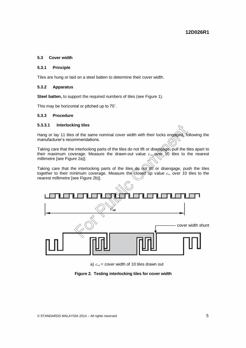
Hang or lay 11 tiles of the same nominal cover width with their locks engaged, following the manufacturer’s recommendations. Taking care that the interlocking parts of the tiles do not lift or disengage, pull the tiles apart to their maximum coverage. Measure the drawn-out value cwd over 10 tiles to the nearest millimetre [see Figure 2a)].
Taking care that the interlocking parts of the tiles do not lift or disengage, push the tiles together to their minimum coverage. Measure the closed up value cwc over 10 tiles to the nearest millimetre [see Figure 2b)].
a) cwd = cover width of 10 tiles drawn out
Figure 2. Testing interlocking tiles for cover width
Figure 2. Testing interlocking tiles for cover width (continued) 5.3.3.2 Non-interlocking tiles Hang or lay 10 tiles of the same nominal cover width on a batten following the manufacturer’s recommendations.
Push the tiles together. Measure the width of the 10 tiles to the nearest millimetre.
5.3.4 Expression of results 5.3.4.1 Interlocking tiles
Calculate to the nearest millimetre either:
a) the mean drawn out value cwd /10 and the mean closed up value cwc / 10; or b) the mean cover width (cwd + cwc ) / 20. 5.3.4.2 Non-interlocking tiles Calculate the mean cover width cwc / 10 to the nearest millimetre. 5.3.5 Test report 5.3.5.1 Interlocking tiles
The test report shall include the following:
a) the mean drawn out value cwd / 10 and the mean closed up value cwc / 10 to the nearest
millimetre; or
b) the mean cover width (cwd + cwc ) / 20 to the nearest millimetre; and
a) the mean cover width cwc / 10 to the nearest millimetre; and
b) reference to this document.
5.4 Batten Lugs and Squareness
5.4.1 Principle Tiles are placed on the test stand to determine shape and squareness of lugs.
5.4.2 Apparatus
Test stand, with appropriate shape and position of batten lugs as shown in Figure 3.
5.4.3 Procedure The test stand shall be placed on a surface that is approximately horizontal and each tile to be tested shall be hung so that its batten lugs rest fully on the top edge of the stand.
5.4.4 Expression of results Measure the distances between the top and bottom corners of the tile and the adjacent side of the stand. Record the differences between the measurements.
5.4.5 Test report
The test report shall include the following:
a) the distances between the top and bottom corners of the tiles adjacent side of the stand; and
Figure 3. Stand for testing batten lug face and squareness
5.5 Flatness
5.5.1 Principle
Tiles are laid on a flat plate to determine their flatness. 5.5.2 Apparatus 5.5.2.1 A flat metal surface or two co-planer flat metal plates, (see Figure 4).
5.5.2.2 Steel round bar, with a diameter of 3 mm or cw / 100 to the nearest millimetre, whichever is the greater. 5.5.3 Procedure
Place the tile on a flat level surface or two co-planer flat metal plates with the nibs projecting, as shown in Figure 4. Hold the tile to ensure that the head of the tile is in contact with the surface.
Using the steel round bar (without lifting the tile), check whether any gap between the lower front edge of the tile and the measuring surface at any nominal contact point, is greater than the diameter of the steel round bar.
5.5.4 Expression of results
Record for each tile whether there is a gap equal to or greater than the diameter of the steel round bar. 5.5.5 Test report The test report shall include the following:
a) the number of tiles for which there is a gap equal to or greater than the diameter of the
steel round bar; and b) reference to this document.
5.6.1 Principle Tiles are hung to determine nib support. 5.6.2 Apparatus 5.6.2.1 Wooden battens, the size of which shall be in accordance with the national fixing specifications or, if they do not exist, the manufacturer’s recommendations for the type of tile to be tested. 5.6.2.2 Wooden packing piece, of appropriate size to ensure correct hanging angle (see Figure 5). 5.6.2.3 Nails, screws or clips, to secure the lower tiles. 5.6.3 Procedure Prepare a vertical surface (90° ± 2°) by fixing wooden battens at the appropriate distance for the tiles to be tested, using a packing piece to ensure the correct hanging position (see Figure 5). Hang the tiles on the battens and: a) if the tiles are laid straight bond, use a single column of tiles [see Figure 5a) and 5b)]; or b) if the tiles are laid broken bond, set up the bottom (first) course with two tiles and place
the test tile in the second course [see Figure 5a) and 5c)]. Secure the lower tile(s) where necessary. Place the test tile in its position without fixings. 5.6.4 Expression of results Record whether or not the tile remains in the test position without falling for at least 1 min. 5.6.5 Test report The test report shall include the following: a) results in accordance with 5.6.4; and b) reference to this document.
Tiles are conditioned and then weigh to determine their masses.
5.7.2 Apparatus Weighing device, capable of measuring to the nearest 25 g. 5.7.3 Conditioning
Store the tiles to be tested at 15 °C to 30 °C and at a minimum of 30 % relative humidity for at least 24 h, in such a manner that air is free to circulate to all sides of each tile.
5.7.4 Procedure
Weigh each tile to the nearest 25 g.
5.7.5 Expression of results
Record the values measured and calculate the mean mass of the tiles in the sample to the nearest 25 g.
5.7.6 Test report
The test report shall include the following: a) the mass of each tile to the nearest 25 g; b) the mean mass of the tiles in the sample to the nearest 25 g; and
c) reference to this document. 5.8 Mechanical resistance (transverse breaking strength)
5.8.1 Principle
Tiles are placed in a test machine and a load is applied in order to determine the mechanical resistance of the tiles.
5.8.2 Apparatus
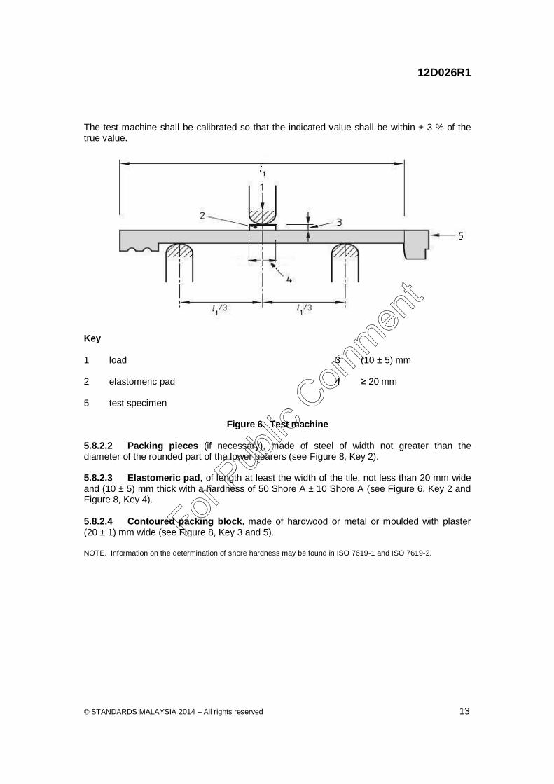
5.8.2.1 Test machine, with two lower rounded metal bearers in a horizontal plane whose centres are spaced at 2/3 of the hanging length of the tile to be tested, and a single rounded metal upper bearer positioned centrally between the two lower bearers (see Figure 6). The bearers shall be circular or rectangular with one rounded side. The rounded part of the bearers shall have a radius of 10 mm to 20 mm. The bearers shall have a minimum width of 20 mm. The upper bearer and the bearer nearest the tail of the tile shall be free to pivot perpendicularly to their long axis. The length of the bearers shall be not less than the width of the tile to be tested.
The test machine shall be calibrated so that the indicated value shall be within ± 3 % of the true value.
Key 1 load 3 (10 ± 5) mm 2 elastomeric pad 4 ≥ 20 mm 5 test specimen
Figure 6. Test machine 5.8.2.2 Packing pieces (if necessary), made of steel of width not greater than the diameter of the rounded part of the lower bearers (see Figure 8, Key 2). 5.8.2.3 Elastomeric pad, of length at least the width of the tile, not less than 20 mm wide and (10 ± 5) mm thick with a hardness of 50 Shore A ± 10 Shore A (see Figure 6, Key 2 and Figure 8, Key 4).
5.8.2.4 Contoured packing block, made of hardwood or metal or moulded with plaster (20 ± 1) mm wide (see Figure 8, Key 3 and 5).
NOTE. Information on the determination of shore hardness may be found in ISO 7619-1 and ISO 7619-2.
Store the tiles to be tested at 15 °C to 30 °C, at a minimum of 30 % relative humidity for at least 24 h, in such a manner that air is free to circulate to all sides of each tile.
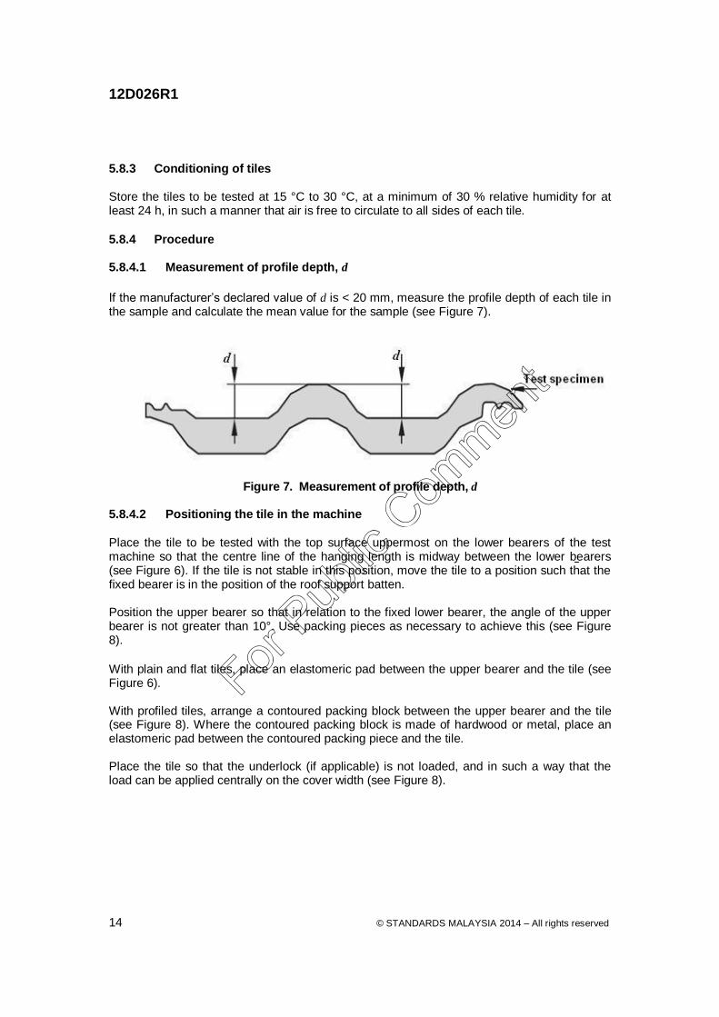
5.8.4 Procedure 5.8.4.1 Measurement of profile depth, d
If the manufacturer’s declared value of d is < 20 mm, measure the profile depth of each tile in the sample and calculate the mean value for the sample (see Figure 7).
Figure 7. Measurement of profile depth, d 5.8.4.2 Positioning the tile in the machine
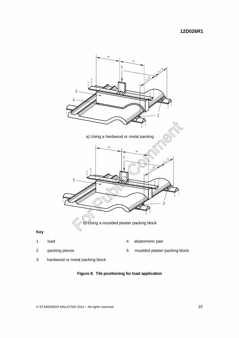
Place the tile to be tested with the top surface uppermost on the lower bearers of the test machine so that the centre line of the hanging length is midway between the lower bearers (see Figure 6). If the tile is not stable in this position, move the tile to a position such that the fixed bearer is in the position of the roof support batten. Position the upper bearer so that in relation to the fixed lower bearer, the angle of the upper bearer is not greater than 10°. Use packing pieces as necessary to achieve this (see Figure 8).
With plain and flat tiles, place an elastomeric pad between the upper bearer and the tile (see Figure 6). With profiled tiles, arrange a contoured packing block between the upper bearer and the tile (see Figure 8). Where the contoured packing block is made of hardwood or metal, place an elastomeric pad between the contoured packing piece and the tile. Place the tile so that the underlock (if applicable) is not loaded, and in such a way that the load can be applied centrally on the cover width (see Figure 8).
b) Using a moulded plaster packing block Key 1 load 4 elastomeric pad 2 packing pieces 5 moulded plaster packing block 3 hardwood or metal packing block
5.8.4.3 Load application Apply the load through the upper bearer at a rate of between 1 500 N/min and 6 500 N/min until failure occurs. 5.8.5 Recording of test results Record the maximum load of each tile to the nearest 10 N. When calculating the total load, include the weight of the packing pieces used on the top surface if they exceed 5 N. 5.8.6 Test report The test report shall include the following: a) the maximum load of each tile to the nearest 10 N; and b) reference to this document. 5.9 Water absorption 5.9.1 Principles Tiles are immersed in water to determine water absorption. 5.9.2 Apparatus 5.9.2.1 Water container, with suitable size. 5.9.2.2 Oven. 5.9.2.3 Weighing device. 5.9.3 Procedure Three test pieces taken from the three tiles fractured in the transverse breaking test and shall be tested for water absorption. The test pieces shall be immersed in water at room temperature for 24 h, then removed and immediately tested in a saturated condition. For ridge-tiles and fittings to be tested for water absorption without being subjected to the transverse breaking test, the required three test pieces shall be immersed in water at room temperature for 24 h, then removed and immediately tested in a saturated condition. Each saturated test piece shall be separately weighed and the individual wet weight recorded. The test pieces shall then be oven-dried at a temperature 100°C to 110°C in a ventilated oven for a period of 24 h, cooled to room temperature, reweighed and the individual dry weight is recorded.
5.9.4 Expression of result The decrease in weight, calculated as a percentage of the oven-dry weight, shall be recorded as the percentage of water absorption. The percentage of water absorption for each of the specimens tested shall be recorded separately, and the average of these shall be taken as the average percentage of water absorption.
5.9.5 Test report The test report shall include the following: a) the average percentage of water absorption of specimens and accessory tiles; and b) reference to this document. 5.10 Water impermeability 5.10.1 Principle Water is applied to the tiles in order to determine their impermeability to water. 5.10.2 Apparatus and materials 5.10.2.1 Impermeable frame, on or around the tile or valley tile. Where a shelf or support points are provided to support the tile, they shall be not more than 15 mm wide. 5.10.2.2 Impermeable material or sealant, to seal the joint between the impermeable frame and tile or valley tile so that it is watertight. 5.10.2.3 Devices for detecting falling drops of water, as shown and illustrated in Figure 9a) is used to detect falling drops of water. However, another method as shown in Figure 9b) can also be considered. 5.10.3 Conditioning Store the tile or valley tile to be tested at 15 °C to 30 °C, at a minimum of 30 % relative humidity for at least 20 h, in such a manner that air is free to circulate to all sides of each tile or valley tile. 5.10.4 Procedure Seal the impermeable frame on or around the tile or valley tile so that no more than 15 mm from the perimeter is covered (see Figure 9). In the case of interlocking tiles with an underlock width of ≤ 30 mm, the seal width shall be not more than half of the width of the underlock on that side. Where functional openings such as fixing holes are present, seal these with an impermeable material. Where the tile has a decorative finish, remove the decorative finish from the face around the outer edge to achieve a watertight seal between the tile and the impermeable frame. Hold the tile or valley tile to within 10° of the horizontal. Pour water on to the tile or valley tile to a level of 10 mm to 15 mm above the highest point, place the test sample above a suitable device for detecting falling drops of water and store at 15 °C to 30 °C and at least 30 % relative humidity for 20 h ± 5 min. 5.10.5 Expression of results Record whether or not drops of water have fallen from the underside of the tile or valley tile during the period of 20 h ± 5 min.
5.10.6 Test report The test report shall include the following: a) whether drops of water have fallen from the underside of the tile; and b) reference to this document.
2 sealant max 15 mm wide 7 two layers of a fine metal mesh with insulating linen between them
3 water impermeable frame 8 measuring amplifier
4 roofing tile 9 recording device
5 mirror
Figure 9. Water impermeability test apparatus (continued)
5.11 Reaction to fire performance in accordance with EN 13823 5.11.1 General Clause 5.11.2 until 5.11.5 refers to test specimen for reaction to fire performance. Test procedure and report shall be as specified in EN 13823. 5.11.2 Principle An agreed standard method of mounting the test specimen is provided to avoid fire penetration through the tiles at the intersection of the long and short wings of the test specimen, because of gaps in the inclined overlapping tiles. 5.11.3 Test specimen assembly The test specimen assembly shown in Figures 10, 11 and 12 shall consist of two timber frames 1.5 m in height, forming a 90° corner. Timber frames shall be constructed using 50 mm × 50 mm timber members. The test specimen area exposed to the burner shall have the following dimensions: a) short wing (495 ± 5) mm × (1 500 ± 5) mm; and b) long wing (1 000 ± 5) mm × (1 500 ± 5) mm.
A non-Fire-Retarded particleboard substrate, for internal use, of thickness (12 ± 2) mm and nominal density (680 ± 50) kg/m
3, Euroclass D of EN 13501-1:2007+A1:2009 (according to
EN 13238:2010) shall be nailed to the timber frames. Vertical timber counterbattens shall be fixed to the substrate using mechanical fixings. Horizontal timber battens shall be mechanically fixed to the counterbattens. The battens shall be positioned to accommodate the manufacturer’s head lap specification. Both the counterbattens and battens shall be of thickness (25 ± 1) mm and width (50 ± 1) mm. Alternatively, counterbatten and batten sizes shall be according to the tile manufacturer’s recommendations provided that their combined thicknesses are not less than 40 mm. A 75 mm × 75 mm metal angle shall be used to protect the corner joint. The angle shall extend over the height of the test specimen and be mechanically fastened to the battens at the corner. High temperature ceramic fibre blanket of density (120 ± 20) kg/m³ shall be used to fill the cavity between the metal angle and the back of the tiles. The fibres of this insulation may consist of silica (SiO2) or of an appropriate metal silicate, e.g. alumino-silicate. Alternatively, they may be formed synthetically from appropriate refractory metal oxides, e.g. alumina or zirconia. The insulation should have a temperature classification of at least 1 100 °C (EN 1094-1:2008). The gap between the tiles abutting at the corner joint shall also be filled with high temperature ceramic fibre blanket or equivalent materials (Figures 10 and 11). It is advisable that the insulation used has a low organic binder content, as any organic material present in the insulation may contribute to the smoke generated during the test. Mineral wool insulation as specified in MS 1020:2010 of density (50 ± 20) kg/m
3 and of at
least Class A2-s1, d0 according to EN 13501-1:2007+A1:2009 shall be used to fill the cavity between the substrate and the calcium silicate backing board. 5.11.4 Laying the tiles in the test specimen assembly The tiles shall be laid at their minimum headlap (as recommended by the manufacturer) and mechanically fixed onto the timber battens. Tiles shall be laid with side laps at the mean cover width. Tiles shall be cut where necessary to fill the test frame. Single lap tiles which require to be cut in length shall be placed in the bottom row (see Figure 11). Where the tiles are designed to be laid in broken bond only, the tiles in the specimen shall be placed with half width tiles on alternate rows at the intersection of the two wings of the test specimen, starting with half width tiles at the bottom row of each wing at the intersection. Where the tiles are designed to be laid in straight or broken bond, the tiles in the test specimen shall be laid in straight bond. Double lap tiles laid in broken bond shall be laid to include a row of overlapping tiles at the top row, and a row of under lapping tiles in the bottom row in both wings, so as to maintain double lapping; these tiles shall be cut in length to provide the specified laps. Profiled tiles shall be mounted in accordance with the requirements of EN 13823:2010, 5.2.2 h) including the arrangements for positioning the tile assembly in relation to the U-profile. Where the tile profile requires part of the bottom row of tiles to be cut and thereby exposing horizontal gaps, a continuous steel Z-profile cover strip shown in Figure 12 and 13 shall be provided in both wings to prevent upward fire penetration.
5.11.5 Closing the gaps between tiles at the corner of the two wings Gaps which occur between tiles meeting at the corner of the two wings of the test specimen shall be closed to prevent fire penetration, (see Figure 10 and 12), by tightly packing with high temperature ceramic fibre blanket or equivalent materials. The high temperature ceramic fibre blanket or equivalent materials shall be applied progressively upwards against the metal backing angle as each row of tiles is being laid. In order to protect the ends of the battens from charring, it is permissible to extend the high temperature ceramic fibre blanket or equivalent materials to fill the spaces between each row of tiles, and the batten faces behind the tiles, for a horizontal distance of no more than 150 mm from the corner of each wing.
Acknowledgement Members of Technical Committee on Bricks and Blocks Name Organisation Prof Dr Badorul Hisham Abu Bakar (Chairman)
Universiti Sains Malaysia
Ms Nor Azwamiza Abu Samah (Secretary) SIRIM Berhad Ir Bruce Chan Siew Keat Association of Consulting Engineers Malaysia Mr Mohd Idrus Din Construction Industry Development Board
Malaysia Mr Jasni Ali Jabatan Bomba dan Penyelamat Malaysia Ir Abd Halim Ibrahim/Ms Tan Lee Lian Jabatan Kerja Raya Malaysia Mr Michael Thong Master Builders Association Malaysia Ar Chong Swee Tshung Pertubuhan Akitek Malaysia Mr Tiah Toh Twin Real Estate and Housing Developers'
Association Malaysia Mr Hanon Nazir Mohd Basir SIRIM QAS International Sdn Bhd (Testing
Services Department - Civil and Construction Section)
Mr Zaini Ahmad SIRIM QAS International Sdn Bhd ( Testing Services Department - Fire Protection Section)
Mr Mohammad Shaharin Ahmad Latif SIRIM QAS International Sdn Bhd (Product Certification and Inspection Department)
Mr Safingi Bidin The Cement and Concrete Association of Malaysia
Brig Gen Sr Haji Mohd Amin Mohd Din Chartered Institute of Building Malaysia Ir Hooi Wing Chuen The Institution of Engineers, Malaysia Assoc Prof Dr Jamaludin Mohamad Yatim Universiti Teknologi Malaysia Prof Dr Ir Che Sobry Abdullah Universiti Utara Malaysia Members Working Group on Concrete interlocking roofing tiles Name Organisation Assoc Prof Dr Jamaludin Mohamad Yatim (Chairman)
Universiti Teknologi Malaysia
Ms Nor Azwamiza Abu Samah (Secretary) SIRIM Berhad Mr Ang Poh Meng ASC Tiles Sdn Bhd Mr Jamri Masran/Mr Law Poh Kiong/ Mr Mohd Khairul Jamil
Jabatan Bomba dan Penyelamat Malaysia
Mr Fadillah Zain Hasirun Ministry of Urban Wellbeing, Housing and Local Government
Mr Nga Song Hoe/Mr Cham Tau Seng Monier Malaysia Sdn Bhd Ar Ng Chin Heng Pertubuhan Akitek Malaysia Mr Hanon Nazir Mohd Basir SIRIM QAS International Sdn Bhd (Testing
Services Department - Civil and Construction Section)
Ms Rohaya Ibrahim SIRIM QAS International Sdn Bhd (Testing Services Department - Fire Protection Section)
Mr Wan Ahmad Jailani Wan Ahmad/ Mr Miswary Mat Yaacob
SIRIM QAS International Sdn Bhd (Product Certification Section)
Brig Gen Sr Haji Mohd Amin Mohd Din Royal Institution of Surveyors Malaysia Assoc. Prof Ir Dr Low Kaw Sai The Institution of Engineers, Malaysia