12S56 GPS Thomas Herring (tah @ mit . edu ), MW 11:00-12:30 Room 54-322 http:// geoweb . mit . edu /~ tah /12S56 09/28-10/12/2009 12S56 Sem 03 2 Todayʼs Seminar • Electronic Distance Measurement (EDM) • History • Methods: – Theory: Propagating electromagnetic signals – Timing signal delays – Use of phase measurements – Application areas (other than GPS)
– Theory: Propagating electromagnetic signals– Timing signal delays– Use of phase measurements– Application areas (other than GPS)
09/28-10/12/2009 12S56 Sem 03 3
How to measure distances• Astronomical measurements tell us position relative to
gravity field. If we want to measure distances directly,how do we do this?
• Rulers: Steel tapes -- good to ~100 meters• Triangulation: Dates from ~1600 and Snell (refraction
of light Snell).• Trilateration: Uses distance measurements
measured remotely (i.e., via a propagating signal:Electromagnetic most common, sound is also possiblebut not accurate)
09/28-10/12/2009 12S56 Sem 03 4
Basic Triangulation• Angles in figure measured and with 1 distance
measured, size and shape of figure can bedetermined
Measued distanceMeasured Angle
Squence throughtriangles
09/28-10/12/2009 12S56 Sem 03 5
History of EDM• Development of this type of technology started during
World War II with the development of RADAR (RadioDetection and Ranging)
• Radars returned the distance to an object (and laterversions the speed of the object through the Dopplershift) by timing the length of time the from thetransmission of a pulse to its return. Accuracy was setby timing resolution (1µsec=300meters)
• In 1949, Dr. Erik Bergstrand of Sweden introduced theGeodimeter (Geodetic Distance Measurement) thatused light (550 nm wavelength) to measure geodeticquality distances (instrument weighed 100kg)
09/28-10/12/2009 12S56 Sem 03 6
Geodimeter• First units circa 1959 (50 kg each for
measurement unit and optics
09/28-10/12/2009 12S56 Sem 03 7
Later model Geodimeter• Example of a latter model Geodimeter (circa 1966)
Front andbackviews
09/28-10/12/2009 12S56 Sem 03 8
History of EDM• Distance range was about 10km during daylight and 25km at
night.• Greater range during daytime was achieved by using radio
waves, and in Dr. T. L. Wadley, South Africa introduced theTelluometer in 1957.
• Instrument used X-band radio waves (~10GHz)• Receive and transmit ends looked similar (receiver actually re-
transmitted the signal) (The Geodimeter used one or more cornercube reflectors.)
• Distances up to 50 km could be measured in daylight with thisinstrument and later models.
09/28-10/12/2009 12S56 Sem 03 9
Telluometer• Example of circa 1962 model.
Back and front ofinstrument (9 kg withcase)
1970ʼs version (1.7kg)
09/28-10/12/2009 12S56 Sem 03 10
Modern versions• These types of measurements are now directly built
into the telescope assemblies of theodolites and youcan see these on most construction sites. The anglesare now also read electronically (compared to glassoptical circles).
• Modern example (circa 2000)
Corner cubereflector, Infraredlight source used
09/28-10/12/2009 12S56 Sem 03 11
Theory of EDM• EDM is based on the idea that light (and radio waves)
travel at a finite velocity and by measuring how long asignal takes travel back and forth between two pointsand knowing the speed of light, the distance can bemeasured.
• However, very few instruments actually make a time-of-flight measurement. Most instruments use a phasemeasurement (actually as series of suchmeasurements). We will see shortly why.
• Start with time-of-flight because concept it is simplethen move to phase (GPS actually uses bothmeasurement types with some interesting twists).
09/28-10/12/2009 12S56 Sem 03 12
Time of flight measurement• In time of flight measurement, a pulse is transmitted
and the time to the return is measured.• Measurement can be made a number of ways:
– Leading edge detection (signal level passes athreshold)
• Accuracy of measurement depends on duration ofpulse
09/28-10/12/2009 12S56 Sem 03 13
Time-of-flight measurement• If a “box-car” is transmitted (i.e., a rectangular pulse),
correlation with another box car, will generate atriangular correlation function.
• The width of this function is twice the pulse length. Anarrower pulse; the more precise the measurement.
• However a perfect box-car is impossible to generatebecause of the instantaneous rise time.
• Nature of pulse is accessed by Fourier transform oftime-domain signal (i.e., its frequency content isdetermined).
09/28-10/12/2009 12S56 Sem 03 14
Pulse characteristics• The Fourier transform of a box car of height C and
duration T seconds is:
• The function on the left is called the sinc function• Notice that the width of the sinc function is 1/T
(between zeros) and that its amplitude decays as 1/f• The equivalent width of a “pulse” is thought of as
1/(frequency range) [called bandwidth]
€
Ce−i2πft−T /2
T /2∫ dt = 4CT sin(4πTf )
4πTf
09/28-10/12/2009 12S56 Sem 03 15
Pulse characteristics• Very narrow pulses, need a large frequency
bandwidth and broad pulses require a smallbandwidth (consider internet data transfer rates)
• In real systems bandwidth is limited by losses in thesystem that attenuate signals away from the center ofthe transmission frequencies (e.g., antennas onlywork around a certain frequency band).
• One of the advantages of optical frequencies is thatsince the frequency is so high (3x10⁶ GHz comparedto GPS at ~1GHz (109 Hz)
09/28-10/12/2009 12S56 Sem 03 16
EM Propagation• Theory of propagation of EM (and interaction with
antennas) is set by Maxwellʼs equations. We will notcover this area except to note that the solution toMaxwellʼs equations for a signal propagating inuniform, isotropic medium can be written as:
• Where E is the electric field, t is time, x is a positionvector and k is the wave vector (vector in direction ofpropagation divided by wavelength λ=v/f
€
r E (x,t) =
r E oe
−i2π ( ft−k⋅x)
09/28-10/12/2009 12S56 Sem 03 17
EM Receiver• All an EM receiver does is sample the E field at a
location (from measuring the current in a an antennainduced by the traveling E field) and convert it into avoltage that can be manipulated (e.g., AM and FMradio).
• If x is fixed, then the k.x term is the phase of theobserved signal. (The 2πft term is removed by de-modulation i.e., multiplying by a signal of the samefrequency).
09/28-10/12/2009 12S56 Sem 03 18
Difference measurement (stays constant withtime and depends on distance)
-1.00
-0.50
0.00
0.50
1.00
0.0 0.4 0.8 1.2 1.6 2.0 2.4 2.8
OutgoingIncomingOutgoing +ΔtIncoming + Δt
Sign
al v
olta
ge
Distance
09/28-10/12/2009 12S56 Sem 03 19
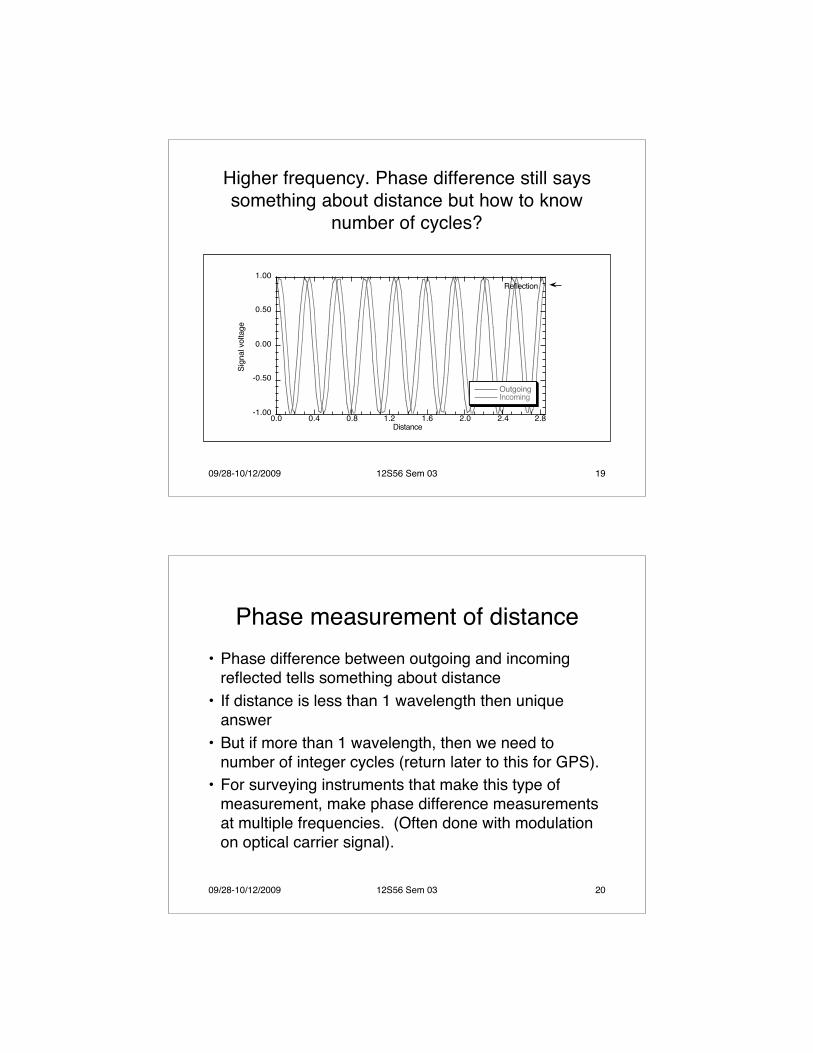
Higher frequency. Phase difference still sayssomething about distance but how to know
number of cycles?
-1.00
-0.50
0.00
0.50
1.00
0.0 0.4 0.8 1.2 1.6 2.0 2.4 2.8
OutgoingIncoming
Sign
al v
olta
ge
Distance
Reflection
09/28-10/12/2009 12S56 Sem 03 20
Phase measurement of distance• Phase difference between outgoing and incoming
reflected tells something about distance• If distance is less than 1 wavelength then unique
answer• But if more than 1 wavelength, then we need to
number of integer cycles (return later to this for GPS).• For surveying instruments that make this type of
measurement, make phase difference measurementsat multiple frequencies. (Often done with modulationon optical carrier signal).
09/28-10/12/2009 12S56 Sem 03 21
Resolving ambiguities• The range accuracy will be low for long-wavelength
modulation: Rule of thumb: Phase can be measuredto about 1% of wavelength
• For EDM: Use multiple wavelengths each shorterusing longer wavelength to resolve integer cycles(example next slide)
• Using this method EDM can measure 10ʼs of km withmillimeter precision
09/28-10/12/2009 12S56 Sem 03 22
Ambiguity example• A typical example would be: Measure distances to 10
km using wavelengths of 20 km, 1 km, 200 m, 10 m,0.5 m
Frequency shifting• In many EDM systems, the modulation frequency can
be changed by small increments and this allowsdistances to be measured by setting the frequency tonull the phase difference between the outgoing andincoming signal.
• We set the frequency such that x/λ1=N (an unknowninteger)
• If the frequency is slowly changed then the phasedifference will be be non-zero, but will return to zeroagain a some slightly different frequency so thatx/λ2=N+1. How do we use this?
09/28-10/12/2009 12S56 Sem 03 24
Frequency shifting• If we are certain that λ1 and λ2 represent exactly one
cycle difference over the distance x (requires finetuning of frequency selector) then the two equationscan be solved for x:
• Many EDMs work this way but notice the sensitivity tothe difference in wavelength€
x /λ1 = Nx /λ2 = N +1 Subtracting the two eqns
x λ1 −λ2
λ1λ2
=1 and x = λ1λ2
λ1 −λ2
09/28-10/12/2009 12S56 Sem 03 25
Application areas• Commercial EDM equipment used by surveyors and
engineers use the frequency changing systems (on amodulated signals and not the carrier frequency).
• Pulsed systems are used by radar and lidar (lightdetection and ranging)
• Satellite laser ranging (SLR) uses a pulsed systemand is capable of getting return signals from the moon(Apollo experiment that still operates) and from earthorbiting satellites (LAGEOS and many others includingsome GPS satellites and all Russian GLONASSsatellites)
09/28-10/12/2009 12S56 Sem 03 26
Issues with EDM• We have looked at a number of methods for
measuring distances electronically. All haveadvantages and disadvantages:– Pulse systems: Pulse duration sets accuracy and to
improve accuracy, average over a number of pulses.But transmitter not running most of the time (haveto wait until pulse returns, low “duty-cycle”
– Phase measurement systems: require changingfrequencies. OK for passive reflector (mirror) butlimits the number of users if active return system(usual for radio systems)
09/28-10/12/2009 12S56 Sem 03 27
Summary of Seminar• Today we covered Electronic Distance Measurement
(EDM)• History• Methods:
– Theory: Propagating electromagnetic signals– Timing signal delays– Use of phase measurements– Application areas (other than GPS)


![[PPT]New Delhi Metro - Massachusetts Institute of Technologyscripts.mit.edu/.../readinggroup/images/6/68/Leonid_PPT.ppt · Web viewNew Delhi Metro Leonid A. Chindelevitch MIT India](https://static.documents.pub/doc/80x56/5affe98e7f8b9a89598bd12a/pptnew-delhi-metro-massachusetts-institute-of-viewnew-delhi-metro-leonid-a.jpg)

![Massachusetts Military Reservation · Otis Air National Guard/Camp Edwards, Falmouth, Massachusetts (Massachusetts Military Reservation [MMR], Cape Cod, Massachusetts)](https://static.documents.pub/doc/80x56/5af853a37f8b9a44658c3974/massachusetts-military-reservation-air-national-guardcamp-edwards-falmouth-massachusetts.jpg)


