12TH INTERNATIONAL BRICK/BLOCK Masonry c ON F EREN CE Qam SEISMIC EVAlUATION OF EXISTING HYATT REGENCY MUlTISTORY MASONRY APARTMENTS BUllDING K. S. AI-JabrP, S. S. AI-Harrasi 2 and M. Qamaruddin 3 'Lecturer, Department of Civil Engineering, Sultan Qaboos University, Oman ' Engineer, Rusail Industrial Estate ' Profes sor. Department of Civil Engineering Aligarh Mu slim University, India ABSTRACT There are several reports of felt earthquakes in the Sultanate of Oman during the pe- riod from years 977 to 1995, although no damage to the existing structures has be- en reported. In view of this, the earthquake hazard potential in the Sultanate of Oman is considered real. In developing a standard code for seismic design of structu- res, seismic zoning map and other basic data are required. Therefore, in the absence of such basic data and the seismic zoning map in Oman, seismic response of an exis- ting Hyatt Regency multistory masonry apartments building is assessed employing the methodology of Uniform Building Code (UBC, 1994). Also, in the absence of data per- taining to the seismic zone factor and the site coefficient, the seismic response study is carried out by assuming appropriate values of these parameters. The results of such investigation are presented in this paper. The results show that some retrofitting me- asures have to be undertaken in order that the existing building may survive in a pos- sible damaging earthquake. Key words: Oman, seismic activity, earthquake, masonry, multistory apartments, hyatt regency. 14
Transcript
12TH INTERNATIONAL
BRICK/BLOCK Masonry c O N F E R E N C E
Qam
SEISMIC EVAlUATION OF EXISTING HYATT REGENCY MUlTISTORY MASONRY
APARTMENTS BUllDING
K. S. AI-JabrP, S. S. AI-Harrasi2 and M. Qamaruddin3
' Lecturer, Department of Civil Engineering, Sultan Qaboos University, Oman
'Engineer, Rusail Industrial Estate
'Professor. Department of Civil Engineering Aligarh Muslim University, India
ABSTRACT
There are several reports of felt earthquakes in the Sultanate of Oman during the period from years 977 to 1995, although no damage to the existing structures has been reported. In view of this, the earthquake hazard potential in the Sultanate of Oman is considered real. In developing a standard code for seismic design of structures, seismic zoning map and other basic data are required. Therefore, in the absence of such basic data and the seismic zoning map in Oman, seismic response of an existing Hyatt Regency multistory masonry apartments building is assessed employing the methodology of Uniform Building Code (UBC, 1994). Also, in the absence of data pertaining to the seismic zone factor and the site coefficient, the seismic response study is carried out by assuming appropriate values of these parameters. The results of such investigation are presented in this paper. The results show that some retrofitting measures have to be undertaken in order that the existing building may survive in a possible damaging earthquake.
There are several reports of felt earthquakes in the Sultanate of Oman during the period from years 977 to 1995 (Dickson, 1986, TCEQM, 1997, 1998). The historical records show that there was a possible damage during Qalhat earthquake. Despite the fact that some regions in Oman experience an occasional felt earthquake ground motions, no structural damage or loss of life has been reported . This is mainly due to that the intensity of these motions is not great. Historical records, however, suggest a possibility of damage during the Qalhat earthquake of 15th century (Dickson, 1986). Some major earthquake events that occurred at a great distance away in southern Iran, Pakistan or Yemen have been reported in Oman. For example, several individuais reported (Dickson, 1986) effects of 27 November 1945 earthquake (M = 8.2) whose epicentre was just off the southeastern Iranian Makran Coast about 470 km from Muscat (in Oman). The structural damage, casualties, and a Tsunami surge have been reported in such ground shaking . An earthquake of magnitude 6.5 measured on Richter scale that occurred in Baluchistan on 18th April 1983 was felt by some persons residing in mult istory buildings in Muscat (590 km from place of earthquake occurrence) and was also felt in Buraimi (in Oman) at an even greater distance (Dickson, 1986). Residents of Salalah region (Southern Oman) felt Yemen earthquake (M = 5.7) of 13th December 1982 but it was not in Northern Oman (Dickson, 1986).
Before 1985, no systematic investigations concerning the seismic activity in Oman has been undertaken. The most severe recorded earthquake magnitude of 8.2 (27 November 1945) is reported (Dickson, 1986) along the northeastern margin of the Arabian Plate. However, there are some seismic data from the National Geophysical Data Center in Denver, Colorado (U.5.A) network (Dickson, 1986). Such seismic data shows the significant seismic activity concentrated along the Zagrous fault zone in an area between 45.0° E to 65.0° E and 10.0° N to 30.0° N. Very few earthquakes had been recorded in Oman before 1980 mainly beca use of the lack of the local seismographic stations or sensitivity of the world seismic network (Dickson, 1986). After 1980, nearly ali of the earthquakes of magnitude ranging from 3.9 to 4.9 on Ritcher scale were reported by new stations in Norway, Sweden and England.
In view of the above fact, the possibility of an earthquake in Oman could never be ruled out. On account of seismic activity, parts of the Sultanate of Oman may fali into a seismic zone such as that an earthquake of MM intensity of VII or greater could occur. But, major part of the Sultanate of Oman may fali into a seismic zone in which a shock of MM intensity up to V and VI could occur.
Considerable efforts have already been made for assessing seismic hazard in the Sultanate of Oman and various other aspects of seismic monitoring in the Sultanate of Oman. In this paper, results of an investigation has been undertaken to evaluate the seismic capability of an existing Hyatt Regency multistory masonry apartments building (Fig. 1) in the Sultanate of Oman is presented. Seismic response determination of the existing building has been done employing the methodology of UBC, 1994. The seismic response study is carried out by selecting the
appropriate basic data in the absence of information concerning the seismic zone facto r and the site coefficient. Based upon the present study, it is envisaged that some appropriate measures may be taken for the existing buildings to withstand any future earthquakes.
2. METHODOLOGY FOR EARTHQUAKE RESPONSE AND BUILDING IDEALlSATION
The methodology for the determination of seismic response presented in this paper is based on the requirements of the UBC, 1994. It is most extensively used in the U.5.A., particularly in the western part of country. The requirements of this building code are intended to achieve satisfactory performance of the structure when subjected to earthquake ground motion. The safety of the structure is not assured in the event of a major earthquake. The objective of the code is that a minor or moderate earthquake will not damage the structure and that a major earthquake will not produce collapse of the structure. The earthquake forces can be divided into three components: a vertical and two horizontais. In the present study, the vertical component of the ground motion is ignored. Only horizontal earthquake motion is considered in two orthogonal directions, but considering one component at a time.
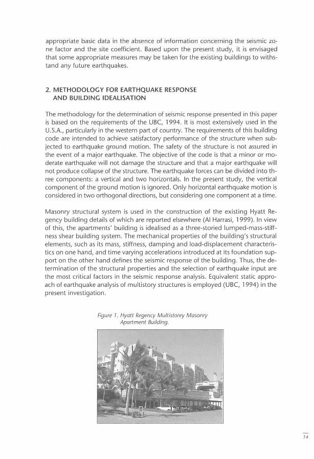
Masonry structural system is used in the construction of the existing Hyatt Regency building details of which are reported elsewhere (AI Harrasi, 1999). In view of this, the apartments' building is idealised as a three-storied lumped-mass-stiffness shear building system. The mechanical properties of the building's structural elements, such as its mass, stiffness, damping and load-displacement characteristics on one hand, and time varying accelerations introduced at its foundation support on the other hand defines the seismic response of the building . Thus, the determination of the structural properties and the selection of earthquake input are the most criticai factors in the seismic response analysis. Equivalent static approach of earthquake analysis of multistory structures is employed (UBC, 1994) in the present investigation.
This method is adopted in most of the building codes for the design of high rise buildings due to its simplicity and the fact that many structures designed on the basis of code coefficients have satisfactorily withstood past earthquakes. To simulate the effects of the designed earthquake, static horizontal forces are applied based on the values of seismic coefficients. The distribution of the shear forces along the height of the building is adopted to be similar to that obtained by dynamic analysis. Design forces specified by most codes are smaller than those indicated by dynamic elastic analysis. The equivalent static method employed in the present study is briefly described in the following paragraphs.
Total Base Shear Force: The total base shear force (V) of the structure is determined using the following relation (UBC, 1994):
ZIWC V=-
Rw
where, W = the seismic weight of the structure; Z = the seismic zone factor; I = the occupancy importance coefficient; Rw = the structural factor; C = dynamic factor = 1.255/T066 :::; 2.75; 5 = the site coefficient; T = the fundamental period of the building .
Distribution of lateral Forces: The lateral force (F.) at a height levei x above the base is determined as:
where Ft = portion of the base force (V) at the top of the structure (O for T:::;O.7 seCo or 0.07TV < 0.25 for T>O.7 sec.); N = total number of stories above the base of the building; Fx = lateral forces applied at levei x;
h" h; = heights of levei x and i above the base of the building; W" W; = seismic weights of xth or ith leveI.
Story Shear Force: The shear at xth story (Vx ) is calculated using the formula :
Drift and Story lateral Displacement: Drift (ó,) and story lateral displacement (õ.) is computed employing:
Óx = VJ Kx Õx = LÓ"
where, K, = flexural stiffness for X'h leveI.
The code stipulates that the story drift should not exceed (0.04/Rw ) times the story height or 0.005 times the story height. The natural period of the building is determined using Rayleigh's method.
Overturning Moment: The overturning moment at X'h levei (M,) of the building is computed by the following equation:
N
M = F, (hN - h,) + L F; (h; - h,) i := 1
Diaphragms are considered flexible when the maximum lateral deformation of the diaphragm is more than twice the average story drift of the associated stories. The provisions (UBC-1994) have been made for the increased shear force resulting from horizontal torsion where diaphragms are flexible. The accidental torsional moment (T,) = 0.05DV" where D is the dimension of the building perpendicular to the direction under consideration.
The code requires that horizontal diaphragms (floors and roofs) be designed to resist the following force given by:
in which Wp, is the weight of the diaphragm and attached parts of the building at the X'h story.
3. DETERMIMATION OF STRUCTURAL ELEMENT PROPERTIES
Determination of the structural properties of the building elements and the selection of earthquake input are the most criticai parameters in the earthquake response computational effort. Seismic weight of the three storied Hyatt Regency hotel masonry building (Fig. 1) has been determined employing its appropriate material and mechanical properties. Details of the seismic weight determination are reported elsewhere (AI Harrasi, 1999). The results of the seismic weight computation of the masonry building are shown in Table 1.
A simplified methodology (Qamaruddin, 1999) has been employed in determining the shear wall stiffness. In this method, the wall is divided into three elements: namely pier, top spandrel and bottom spandrel. Then the three non-dimensional parameters (pier aspect ratio, top and bottom spandrel aspect ratio) are evaluated for different walls. Employing the appropriate tables (Qamaruddin, 1999), the stiffness of the walls has been determined. In the present study, the
146S
1470
stiffness of the walls parallel to transverse (T) and longitudinal (L) directions of the building has been computed separately as illustrated in Fig. 2. This has been conducted based on the assumption that the shear walls located parallel to the transverse direction of the building would resist any expected earthquake ground motion occurring in this direction. Similarly, walls located in the longitudinal direction of the building, would be anticipated to resist any earthquake motion in the longitudinal direction of the building. Details of the stiffness determination of the shear walls are reported elsewhere (AI Harrasi, 1999). Fig. 2 shows plan of Hyatt Regency Apartments for first and second and third floors which were used in computation of the stiffness and stiffness ratio for shear walls located parallel to T- and L-directions. The stiffness of each shear wall has been determined using the methodology as discussed in the preceding paragraph. Also, the stiffness ratio of each shear wall is determined. The stiffness of the shear walls parallel to Tand L-directions for each storey is presented in Table 1.
Figure 2. Floor Plan of the HYatt Regency Building.
1700 6600 2600 1700 3400
H' -I- -I- -I- -I
TW3 rw,
TW1Q TWl1
TW16 TWl1
TW29
..... +... ···1
~ TW32
Third Floor First and Second Floor
TW1 , TW2 .. etc. are wall1 , wall2, .... etc. parallel to T-direclion LW1, LW2 .. etc.are wall1 , wall2, .... etc. pa ra llel to L-direction
Table 7. Data for Earthquake Response Computation.
Story levei Height Seismic Stiffness (kN/m) Stiffness (kN/ m) (m) weight (kN) (in T·direction') (in L·direction+)
3 3.5 3464 1313189 870270
2 3.5 7487 2472304 2779108
1 3.5 7487 2472304 2779108
, T·shear walls parallel to earthquake motion in transverse direction. + L·shear walls parallel to earthquake motion in longitudinal direction.
4. DATA FOR SEISMIC RESPONSE
In the absence of appropriate data for seismic response study, it is assumed that the Hyatt Regency hotel building is located in a seismic zone equivalent to seismic zone 3 (UBC-94) and hence seismic zone facto r Z = 0.15 has been used. Furthermore, the foundation soil of the hotel building is considered such that the site coefficient S =
1.0. The structural facto r (Rw), the occupancy importance factor (I) and the time coefficient facto r (C,) are selected as 6.0, 1.0 and 0.02, respectively, in accordance with the appropriate building material and building system of the Hyatt Regency hotel.
5. DESIGN OF THE SHEAR WALLS
Experiences with past earthquakes have shown that buildings which are unsymmetrical in plan have greater susceptibility to earthquake damage than the symmetrical structures. Torsional effect has been taken into consideration in the present study. Torsion is assumed to occur when the centroid of rigidity of the various vertical resisting elements in a story fails to coincide with the center of gravity. The distance between the two, called the eccentricity e, times the amount of the lateral force is a torsional moment that must be resisted in addition to and simultaneously with the normal design lateral force. The determination of the torsional shear and the direct lateral shear is fully explained elsewhere (AI Harrasi, 1999).
The stresses on the walls from the load and moments may be obtained from the following expression:
" = N/Lh ± 6M/hL2
where N = ultimate load; M = ultimate in-plane moment; L = length of wall; H = thickness of the wall.
The area of tension reinforcement (if required) may be determined by calculating the total tensile force:
T=0.5"L,h
where L, = length of wall in mm where the maximum tensile stress occurs.
74 71
1472
The area of tension reinforcement may be given by:
A" = TI (0.87fy)
where fy = yield strength of reinforcement
Similar approach may be adopted to calculate the area of compression reinforcement.
6. DISCUSSION OF RESUL TS
Earthquake response of Hyatt Regency Hotel Apartments have been determined by applying UBC 94 design procedure. The apartments were assumed to experience earthquake ground motion in two orthogonal directions (longitudinal and transverse). Since the Sultanate of Oman is situated in seismic zone of moderate activity, the hotel apartments were analysed adopting seismic zone 3 and site coefficient of 1.2. The main findings from the present study are explained below:
Table 2 shows the story-wise variation of lateral force, shear force and overturning moment from which it may be seen that there is a definite trend for the variation of the shear force and overturning moment. The maximum overturning moment was achieved at the base and it is decreasing as the story levei increases. Similarly, the largest shearing force was calculated at the first floor reducing with the increase in height. Also, it was observed that there is no definite trend for variation of lateral force since for the second floor the lateral force was greater than those for the first and the third floors.
The story-wise drift, lateral displacement and torsional moment of the building subjected to ground motion in both longitudinal and transverse directions are shown in Table 3. The story drift in the transverse direction was maximum at the first levei decreasing with the increasing story levei whereas there was no definite trend for the variation of story drift in the longitudinal direction. For instance the drift for the first and second leveis was 0.00046 m and for the second story was 0.00036 m. Howe-
Table 2. Lateral Force, Shear Force and Overturning Moment.
Story levei Lateral force, Fx Shear force, (kN) Vx (kN))
3 400 400
2 479 979
1 289 1268
Base
Table 3. Story Drift, Lateral Displacement and Torsional Moment.
Story levei Story Drift (m)
T' L'
3 0.00030 0.00046
2 0.00040 0.00036
1 0.00052 0.00046
T' Earthquake ground motion in longitudinal direction. L' Earthquake ground motion in longitudinal direction.
Lateral Displacement (m)
T' L'
0.00122 0.001 28
0.00092 0.00082
0.00052 0.00046
Overturning Moment (kN.m)
4210
11062
15498
Torsional Moment (kN.m)
T' L'
870 320
2124 782
2750 101 4
ver, the maximum lateral displacement of the walls (at story 3) was comparable in both directions due to the fact that there was small difference in the total stiffnesses of the walls in both longitudinal and transverse directions. The greatest torsional moment was calculated at the first levei and decreasing with the increase in height.
Table 4 shows the primary and secondary moments in T- and L- directions from which it may be seen that there is indiscernible difference in the calculated primary moments for both directions. However the computed story-wise secondary moments in longitudinal direction are slightly higher than those in transverse direction.
The storey-wise computed diaphragm forces are presented in Table 5 along with the extreme values (maximum and minimum) for comparison. It may be seen that the diaphragm forces for the first and second leveis are within the safe limits whereas the diaphragm force for the third floor is higher than the maximum value. This is suggesting that the diaphragm is unsafe and therefore strengthening of the diaphragm is required to ensure that it would perform safely under future earthquake attack.
Tables 6 and 7 show the behaviour of the shear walls in the first, second and third floor subjected to ground motion in L- and T- directions respectively. It may be seen that the majority of the walls failed under the ground motion in both the di-
Table 4. Primary (M,p) and Secondary (M,J Moments.
SIOry levei M., (kN.m) M .. (kN.m) Ralio of M./ M.,
Table 6. Response of the Shear Walls Subjected to Ground Motion in L-direction.
Reinforcemenl Wall Type Floors Remarks
A" (mm')
LW1 1 #, 2+, 3' Safe#, Unsafe in T+: 19+, 104'
LW2 1#, 2+, 3' Unsafe in T 1291 #,1014+,1120'
LW3 1#, 2+, 3- Unsafe in T#,+, Unsafe in T&C' 17924#,12855+,20406'
LW4 1#,2+,3' Unsafe in T 17718#,12536+,12628'
LW5 1#, 2+, 3' Unsafe in T#,+, Safe' 89#,88'
LW6 1#, 2+, 3' Safe#,+, Unsafe in T' 90'
LW7 1#, 2+, 3' Safe#,+, Unsafe in T' 17'
LW8 1 #,2+, 3' Unsafe in T 211 #,47+,164'
#, +, ' : Corresponding lo the first, second and third floor respectively, T: Tension, C: Compression. Ast, Ase: Area of tension and compression reinforcement required respeclively.
A." (mm')
7390'
747,
Table 7. Response or the Shear Walls Subjected to Ground Motion in L-direction.
Reinforcement Wall Type Floors Remarks
A,, (mm') A,, (mm')
LW1 1',2', 3' Safe', Unsafe in 1',' 19+,104'
TW1 1',2', 3' Unsafe in T 49',231+)42'
TW2 1',2',3' Unsafe in T 701',655+,518'
TW3 1',2',3' Unsafe in C', Safe', Unsafe in T' 268' 1422'
TW4 1',2',3' Unsafe in T&C', Unsafe in 1', Unsafe in T' 712'.120+,435' 596'
TW5 1',2',3' Unsafe in T 238',492+,385'
TW6 1',2', 3' Unsafe in T 387',493+,502'
TW7 1',2', 3' Unsafe in C''', Unsafe in T' 12' 594',6+
TW8 1',2", 3* Unsafe in T 80',133+,11 2'
TW9 1',2',3' Unsafe in T&C', Unsafe in T', Unsafe in T' 712'.120+)58' 596'
TW10 1',2', 3' Unsafe in C', Safe', Unsafe in T' 249' 14
TW11 1',2', 3' Unsafe in T 698',658+774'
TW12 1',2', 3' Unsafe in T&C', Unsafe in 1',' 712'.120+,357' 596'
TW13 1',2', 3' Unsafe in T 829',1008+,10'
TW14 1',2', 3' Unsafe in T 385', 492+,102'
TW15 1',2', 3' Unsafe in C', Unsafe in T',' 6+)40' 594'
TW16 1',2', 3' Unsafe in T 80', 133+, 230'
TW17 1',2',3' Unsafe in T&C', Unsafe in l'" 712'.120+,502' 596'
TW18 1',2',3' Unsafe in T&C', Unsafe in T'" 712',720+,330' 596'
TW19 1',2', 3' Unsafe in T 60', 373+, 7'
TW20 1',2',3* Unsafe in T 387',493+,93'
TW21 1',2',3' Unsafe in C', Unsafe in T',' 6+)21' 594'
TW22 1',2',3' Unsafe in T 80', 133+, 212'
TW23 1',2',3' Unsafe in T&C', Unsafe in l'" 712',720+,667' 596'
TW24 1',2', 3' Unsafe in T&C', Unsafe in T'" 712'.120+,302' 596'
TW25 1',2', 3' Unsafe in T 829',1008+,5'
TW26 1',2', 3' Unsafe in T 385', 492+,83'
TW27 1',2', 3' Unsafe in C', Unsafe in T'" 6+)03' 594'
TW28 1',2', 3' Unsafe in T 80', 133+, 193'
TW29 1',2',3' Unsafe in T&C', Unsafe in T +,' 712', 720+,424' 596'
TW30 1',2', 3' Unsafe in T&C', Unsafe in T +,' 712'.120+)75' 596'
TW31 1',2', 3' Unsafe in T 60', 373+, 180'
TW32 1',2', 3' Unsafe in T 387',493+)0'
TW33 1',2', 3' Unsafe in T&C', Unsafe in T'" 712'.120+,5' 596'
TW34 1',2' Unsafe in T 60', 373+'
TW35 1',2' Unsafe in T 387',493+
TW36 1',2' Unsafe in C', Safe' 625'
TW37 1',2' Unsafe in T 177',59+
TW38,TW39 1',2' Unsafe in T&C', Unsafe in l' 1082',571 + 1081'
TW40 1',2' Unsafe in T 1363',594+
TW41 1',2' Unsafe in T 668')82+
TW42 1',2' Unsafe in C', Safe' 625'
TW43 1',2' Unsafe in T 177',59+
TW44,TW45 1',2' Unsafe in T&C', Unsafe in T' 1082',571+ 1081 '
TW46 1',2' Unsafe in T 451'.12+
TW47 1',2' Unsafe in T 666')81+
74 74
Table 7, Response of the Shear Walls Subjected to Ground Motion in L-direction (cont.),
Reinforcement Wall Type Floors Remarks
A" (mm') A. (mm')
TW48 1', 2' Unsafe in C, Safe' 62S '
TW49 1',2- Unsafe in T 177',59'
TW50 1',2' Unsafe in T&C, Unsafe in T' 1082', 571 '
TW51 1',2' Unsafe in T&C, Unsafe in T' 1082',571 '
TW52 1',2' Unsafe in T 1363',594'
TW53 1',2- Unsafe in T 668',282'
TW54 1',2' Unsafe in C, Safe' 625'
TW55 1', 2' Unsafe in T 177',59'
TW56,TW57 1', 2' Unsafe in T&C, Unsafe in T' 1082',571 ' 1081 '
TW58 1', 2' Unsafe in T 451 ')2'
TW59 1',2' Unsafe in T 666',281 '
TW60 1',2' Unsafe in C', Safe' 625'
TW61 1',2' Unsafe in T 177',59'
TW62,TW63 1', 2' Unsafe in T&C, Unsafe in T' 1082',57l' 1081 '
TW64 1',2- Unsafe in T 629',191 '
TW65 1',2' Unsafe in T 666',281 '
TW66 1',2' Unsafe in T 282',51 '
reetions indieating that the hotel apartments are unsafe when subjeeted to an earthquake with an intensity similar to the designed one, Therefore, the amount of (tension and/or compression) reinforeement required to ensure that these walls would perform satisfaetorily subjeeted to an earthquake motion with similar seismie intensity is presented in both tables,
7. CONClUSIONS
Sinee eenturies, Oman is exposed to the risk of earthquakes due to its loeation in a seismieally aetive region. Therefore, the possibility of an earthquake of MM intensity of VII or greater eould never be ruled out, This paper has evaluated the seismie eapability of an existing Hyatt Regeney multistorey masonry apartments building in the Sultanate of Oman. Seismie response determination of the hotel has been eondueted employing the methodology of UBe, 1994. From the results, it was found that ground motion effeets were not eonsidered when designing the strueture sinee the majority of the apartments walls were found unsafe under an earthquake attaek in both transverse and longitudinal direetions. Therefore, the amount of reinforeement required to ensure that these walls would perform safely are ealeulated. Also strengthening of some diaphragms are neeessary, sinee almost ali of these were designed for gravity loads only and eonsidered unsafe under the combination of lateral and gravity loads. Seismie design regulations have to be introdueed in order to ensure that the buildings in the Sultanate of Oman would withstand earthquakes in the future,
141j
1476
REFERENCES
INTERNATIONAL CONFERENCE OF BUILDING OFFIClALS (1994). Uniform Bui/ding Code (UBC). Whittier, CA.
DICKSON, P. (1986). Pre/iminary Assessment of the Earthquake Hazard in the Sultanate of Oman, UNDP Consultancy Mission Report.
TCEQM. 1998. Reports on Earthquakes Recorded by Portable Seismographs, Technical Committee on Earthquake Monitoring, Sultanate of Oman (Unpublished).
TCEQM . 1999. Reports on Earthquakes Recorded by Portable Seismographs, Technical Committee on Earthquake Monitoring, Sultanate of Oman (Unpublished).
AI Harrasi, Suleiman S. M. (1999). Seismic Ana/ysis and Design of a Mu/tistorey Masonry Bui/ding. Project Report, Department of Civil Engineering, Sultan Qaboos University, Oman.
QAMARUDDIN, M. (1999). In-Plane Stiffness of Shear Walis with Openings. J. of Building and Environment, 24, pp. 109-127.