34
Fire Safety & Security Products Siemens Building Technologies 1/3” CMOS Ultra Wide Dynamic Color Camera CCWC1345-LX CCWC1345-MX Configuration Manual

Fire Safety & Security ProductsSiemens Building Technologies
1/3” CMOS Ultra Wide Dynamic Color Camera CCWC1345-LX CCWC1345-MX
Configuration Manual

Liefermöglichkeiten und technische Änderungen vorbehalten. Data and design subject to change without notice. / Supply subject to availability. © 2006 Copyright by Siemens Building Technologies AG Wir behalten uns alle Rechte an diesem Dokument und an dem in ihm dargestellten Gegenstand vor. Der Empfänger erkennt diese Rechte an und wird dieses Dokument nicht ohne unsere vorgängige schriftliche Ermächtigung ganz oder teilweise Dritten zugänglich machen oder außerhalb des Zweckes verwenden, zu dem es ihm übergeben worden ist. We reserve all rights in this document and in the subject thereof. By acceptance of the document the recipient acknowledges these rights and undertakes not to publish the document nor the subject thereof in full or in part, nor to make them available to any third party without our prior express written authorization, nor to use it for any purpose other than for which it was delivered to him.
Dear Customer
By selecting this SIEMENS product, you have chosen a professional device that guarantees the highest possible quality and reliability. We would like to thank you very much for your confidence in our products and kindly ask you to read the following instructions carefully before installing and using the product, in order to take full advantage of all quality features included in this product line.
WARNING
To reduce the risk of fire or electrical shock, do not expose this product to rain or moisture. It should be installed by a qualified service person and should conform to all local codes. Please connect the equipment to a 12 V DC or 24 V AC Class 2 power supply if the LP camera model is to be installed.

3
Siemens Building Technologies Fire Safety & Security Products 08.2006
Contents 1 General information................................................................................5 1.1 Work safety information ............................................................................5 1.2 Electromagnetic compatibility (EMC)........................................................5 1.3 Manufacturer's declaration of conformity ..................................................6
2 General guidelines..................................................................................7 2.1 Operation and storage ..............................................................................9 2.2 Cleaning ....................................................................................................9 2.3 Transportation ...........................................................................................9 2.4 CMOS characteristics ...............................................................................9
3 Technical data .......................................................................................10 3.1 Dimensions .............................................................................................10 3.2 Product specifications .............................................................................10
4 Ordering data.........................................................................................12 4.1 Package contents....................................................................................12
5 Camera part and connector definition................................................13 5.1 Camera part definition.............................................................................13 5.2 Connector pin definition ..........................................................................14 5.2.1 Control switch for twisted pair video out .................................................14 5.2.2 RS485 termination ..................................................................................14 5.2.3 IRIS pin assignment................................................................................14 5.2.4 Y / C terminal ..........................................................................................14 5.2.5 External control terminal .........................................................................15 5.3 OSD setting hierarchy.............................................................................16
6 Install the camera..................................................................................18 6.1 Installation ...............................................................................................18 6.1.1 Using BNC composite video output ........................................................18 6.1.2 Using twisted pair video output ...............................................................18 6.2 Function settings.....................................................................................19 6.2.1 PRESET..................................................................................................19 6.2.2 CAMERA SETUP....................................................................................19 6.2.2.1 EXPOSURE ............................................................................................19 6.2.2.2 SHUTTER ...............................................................................................19 6.2.2.3 LENS LEVEL...........................................................................................20 6.2.2.4 WB MODE...............................................................................................20 6.2.2.5 GAIN .......................................................................................................20 6.2.2.6 GAMMA...................................................................................................21 6.2.2.7 APERTURE.............................................................................................21 6.2.2.8 WD-LEVEL..............................................................................................21 6.2.3 D/N SETUP.............................................................................................21 6.2.3.1 D/N MODE ..............................................................................................22 6.2.3.2 D/N LEVEL..............................................................................................22 6.2.3.3 D/N DELAY .............................................................................................22 6.2.4 OPTION ..................................................................................................22 6.2.4.1 Mirror.......................................................................................................23 6.2.4.2 DZOOM...................................................................................................23 6.2.4.3 DZOOM IN OUT......................................................................................23 6.2.4.4 DZOOM P/T SET ....................................................................................23 6.2.4.5 CHROMA ................................................................................................23 6.2.4.6 COLOR BAR...........................................................................................24 6.2.4.7 DNR ........................................................................................................24

4
Siemens Building Technologies Fire Safety & Security Products 08.2006
6.2.4.8 BACKFOCUS..........................................................................................24 6.2.4.9 SYSTEM..................................................................................................24 6.2.5 OTHER SETUP.......................................................................................24 6.2.5.1 CAMERA ID ............................................................................................25 6.2.5.2 ALARM....................................................................................................25 6.2.5.3 ALARM TEXT..........................................................................................25 6.2.5.4 ALARM ACTION .....................................................................................25 6.2.5.5 ALARM DELAY .......................................................................................25 6.2.5.6 MOTION..................................................................................................26 6.2.5.7 MOTION LEVEL......................................................................................26 6.2.5.8 MOTION AREA .......................................................................................26 6.2.5.9 SET ZONE POSI.....................................................................................26 6.2.5.10 SET ZONE SIZE ....................................................................................26 6.2.5.11 SET ZONE MOVE..................................................................................27 6.2.5.12 MOTION TEXT.......................................................................................27 6.2.5.13 ALARM OUT ..........................................................................................27 6.2.5.14 MOTION DELAY ....................................................................................27 6.2.6 REMOTE.................................................................................................28 6.2.6.1 ADDRESS...............................................................................................28 6.2.6.2 PROTOCOL ............................................................................................28 6.2.6.3 BAUD RATE............................................................................................28 6.2.7 PRIVACY ZONE .....................................................................................28 6.2.8 BLC ZONE ..............................................................................................29 6.2.9 SYNC MODE...........................................................................................30 6.2.10 BACK.......................................................................................................30 6.2.11 EXIT ........................................................................................................30 6.2.12 CANCEL..................................................................................................30 6.2.13 DEFAULT................................................................................................30
7 Maintenance...........................................................................................31
8 Disposal .................................................................................................31
9 Keyword index.......................................................................................32

General information
5
Siemens Building Technologies Fire Safety & Security Products 08.2006
1 General information
1.1 Work safety information
Read these instructions carefully before connecting the camera in order to avoid damage caused by improper installation or use.
Installation may be done only by authorized personnel according to the local safety regulations.
Operate the camera only with the designated voltage. Follow the safety instructions for the camera. Never use the camera for purposes other than those designated. Repairs and adjustments to the camera may be done only by authorized per-sonnel.
If liquids or objects get into the housing, disconnect the camera from the power supply and have it checked by your authorized dealer before using it again. (Danger of electric shock!)
This equipment has been tested and found to comply with the limits for a Class B digital device. These limits are designed to provide reasonable protection against harmful interference in a residential installation.
This equipment may generate, uses and can radiate radio frequency energy and, if not installed and used according to instructions, may cause harmful inter-ference with radio communications.
Be aware that any modifications not explicitly approved in this manual may void your equipment warranty.
The shielded interface cable recommended in this manual must be used with this equipment in order to comply with the limits for a digital output device.
1.2 Electromagnetic compatibility (EMC)
This product has been designed for use in general-purpose CCTV applications in a residential, business or industrial environment. Please contact the supplier of this product if you intend to use it in medical, intrinsically safe installations or in an in-dustrial EMC environment.
To ensure normal operation and to avoid EMC problems, the product must be in-stalled according to the currently valid EMC installation guidelines.
To meet the CE norms, enclosed EMI-cores should be applied to the Y/C and power cable (please refer to chapter 7.1).

General information
6
Siemens Building Technologies Fire Safety & Security Products 08.2006
1.3 Manufacturer's declaration of conformity
This product complies with the requirements of the European Directives 89/336/EEC “Directive of Electromagnetic Compatibility” and 73/23/EEC “Low Voltage Directive”. The EU declaration of conformity is available to the responsible agencies at:
Siemens Building Technologies Fire & Security Products GmbH & Co. oHG D-76181 Karlsruhe
European Directive 89/336/EEC „Electromagnetic Compatibility”
Compliance with the European Directive 89/336/EEC has been proven by testing according to the following standards:
Emitted interference: EN 61000-6-3
EN 55022 Class B Interference resis-tance:
EN 50130-4
European Directive 73/23/EEC „Low-Voltage Directive”
Compliance with the European Directive 73/23/EEC has been proven by testing according to the following standard:
Safety: EN 60950-1

General guidelines
7
Siemens Building Technologies Fire Safety & Security Products 08.2006
2 General guidelines
Read instructions: All the safety and operating instructions should be read before the product is op-erated.
Retain instructions: The safety instructions and the instruction manual should be retained for future reference.
Heed warnings: All warnings on the product and in the instruction manual should be adhered to.
Follow instructions: All operating and use instructions should be followed.
Attachments: Do not use attachments not recommended by the video product manufacturer as they may cause hazards.
Water and moisture: Do not use this video product near water, for example near a bath tub, wash bowl, kitchen sink, or laundry tub, in a wet basement, or near a swimming pool and the like.
Accessories: Do not place this video product on an unstable cart, stand, tripod, bracket or ta-ble. The video product may fall, causing serious injury to a child or adult, and se-rious damage to the product. Use only with the stand, tripod, bracket, or table recommended by the manufacturer or sold with the video product. Any mounting of the product should follow the manufacturer's instructions, and should use a mounting accessory recommended by the manufacturer.
Ventilation: This video product should never be placed near or over a radiator or heat regis-ter.
Power sources: This video product should be operated only from the type of power source indi-cated on the marking label. If you are not sure of the type of power supply to your location, consult your product dealer.
Power-cord protection: Power supply cords should be routed so that they are not likely to be walked on or pinched by items placed upon or against them, paying particular attention to cords at plugs, screws and the point where they exit from the product.
Lightning: For added protection for this video product during a lightning storm, or when it is left unattended and unused for long periods of time, unplug it from the wall outlet and disconnect the power supply and cable system. This will prevent damage to the video product due to lightning and power-line surges.
Overloading: Do not overload power supply and extension cords as this can result in a risk of fire or electrical shock.

General guidelines
8
Siemens Building Technologies Fire Safety & Security Products 08.2006
Object and liquid entry: Never push objects of any kind into this video product through openings as they may touch voltage points or short-cut parts that could result in a fire or electrical shock. Never spill liquid of any kind on the video product.
Servicing: Do not attempt to service this video product yourself as opening or removing covers may expose you to dangerous voltage or other hazards. Refer all servic-ing to qualified service personnel.
Damage requiring service: Disconnect this video product from the power supply and refer servicing to quali-fied service personnel under the following conditions: a. When the power-supply cord or plug is damaged. b. If liquid has been spilled, or objects have fallen into the video product. c. If the video product has been exposed to rain or water. d. If the video product does not operate normally by following the operating in-
structions in the instruction manual. Adjust only those controls that are cov-ered by the instruction manual as an improper adjustment of other controls may result in damage and will often require extensive work by a qualified technician to restore the video product to its normal operation.
e. If the video product has been dropped or the cabinet has been damaged. f. When the video product exhibits a distinct change in performance this indi-
cates a need for service. Replacement parts: When replacement parts are required, be sure the service technician has used replacement parts specified by the manufacturer that have the same characteris-tics as the original part. Unauthorized substitutions may result in fire, electric shock.
Safety check: Upon completion of any service or repairs to this video product, ask the service technician to perform safety checks to determine that the video product is in proper operating condition.
CAUTION The lightning flash with arrowhead symbol, within an equilateral triangle, is intended to alert the user to the presence of un-insulated "dangerous voltage" within the product's enclosure that may be of sufficient magnitude to constitute a risk of electric shock to persons.
CAUTION
The exclamation point within an equilateral triangle is intended to alert the user to the presence of important operating and maintenance (servicing) instructions in the literature accompanying the appliance.
NOTE Tips and information.
General guidelines
9
Siemens Building Technologies Fire Safety & Security Products 08.2006
2.1 Operation and storage
Avoid filming very bright objects (such as lighting fixtures) for an extended pe-riod.
Do not operate or store the unit in the following locations: – Extremely hot or cold places. – Close to sources of strong magnetic fields. – Close to sources of powerful electromagnetic radiation, such as radios or TV
transmitters. – In humid or excessively dusty places. – Where exposed to mechanical vibrations. – Close to fluorescent lamps or objects reflecting light. – Under unstable or flickering light sources.
Do not attempt to service this unit yourself unless you are authorized to do so. Opening the camera may expose you to dangerous voltages or other hazards. Refer all servicing to qualified personnel only.
2.2 Cleaning
Do not touch the imaging surface of sensor. Use a soft cloth moistened with alco-hol to clean the surface if it is touched accidentally.
2.3 Transportation
Use the original packing material or materials of equal quality.
2.4 CMOS characteristics
The following conditions may be observed when using a CMOS camera. These are inherent in the design and do not stem from any fault in the camera itself.
Vertical smear This phenomenon occurs when viewing a very bright object.
Patterned noise This is a fixed pattern, which may appear over the entire moni-tor screen when the camera is operated at a high temperature or in low luminance environment.
Jagged picture When viewing stripes, straight lines, or similar patterns, the image on the screen may appear jagged.
Technical data
10
Siemens Building Technologies Fire Safety & Security Products 08.2006
3 Technical data
3.1 Dimensions
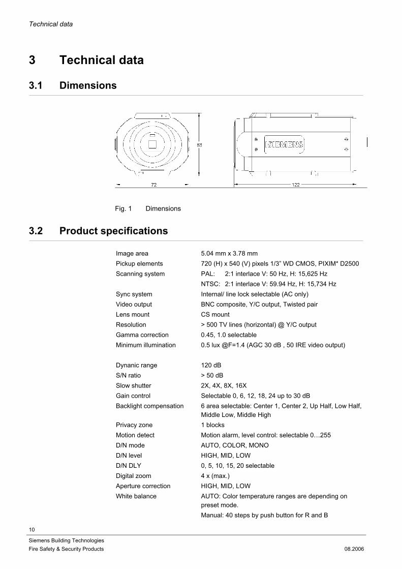
Fig. 1 Dimensions
3.2 Product specifications
Image area 5.04 mm x 3.78 mm Pickup elements 720 (H) x 540 (V) pixels 1/3” WD CMOS, PIXIM* D2500 Scanning system PAL: 2:1 interlace V: 50 Hz, H: 15,625 Hz
NTSC: 2:1 interlace V: 59.94 Hz, H: 15,734 Hz Sync system Internal/ line lock selectable (AC only) Video output BNC composite, Y/C output, Twisted pair Lens mount CS mount Resolution > 500 TV lines (horizontal) @ Y/C output Gamma correction 0.45, 1.0 selectable Minimum illumination 0.5 lux @F=1.4 (AGC 30 dB , 50 IRE video output)
Dynanic range 120 dB S/N ratio > 50 dB Slow shutter 2X, 4X, 8X, 16X Gain control Selectable 0, 6, 12, 18, 24 up to 30 dB Backlight compensation 6 area selectable: Center 1, Center 2, Up Half, Low Half,
Middle Low, Middle High Privacy zone 1 blocks Motion detect Motion alarm, level control: selectable 0…255 D/N mode AUTO, COLOR, MONO D/N level HIGH, MID, LOW D/N DLY 0, 5, 10, 15, 20 selectable Digital zoom 4 x (max.) Aperture correction HIGH, MID, LOW White balance AUTO: Color temperature ranges are depending on
preset mode. Manual: 40 steps by push button for R and B
Technical data
11
Siemens Building Technologies Fire Safety & Security Products 08.2006
Iris control DC iris for galvano lens Camera text 24 characters OSD control 5 control keys on the side-panel of camera Default settings Preset: IN Door (2900 °K – 6500 °K), OUT Door
(2900 °K – 9500 °K) Default settings Default setting restored by pushing the DEFAULT buttonRemote control RS-485: Siemens-B/ -S/ -U protocol, MOLYNX-D Twisted Pair Video Twisted Pair Video out Alarm IN 1CH Alarm OUT NC, BW, OUT selectable Tripod thread A (1/4); ¼ inch on bottom and top Power source
CCWC1345-LX: DC 12 V ±10% regulated power supply AC 24 V ±10%, 50/60 Hz
CCWC1345-MX: AC 100 - 240 V ±10%, 50/60 Hz
Power consumption CCWC1345-LX: 4 VA (max.) CCWC1345-MX: 4.5 VA (max.) Ambient conditions -10 - +55 °C / 95% max relative humidity,
no condensation Dimensions in mm 122 (L) x 72 (W) x 63 (H) Weight 550 g (max.)
*) PIXIM and Digital Pixel System are registered trademarks of PIXIM, Inc. All rights reserved.

Ordering data
12
Siemens Building Technologies Fire Safety & Security Products 08.2006
4 Ordering data
Designation Order No. Approx. Weight (kg)
CCWC1345-LX 1/3” CMOS Ultra Wide Dynamic Color Camera, 500 TVL, PAL/NTSC, 12 V DC / 24 V AC
2GF1183-8HA 0.45
CCWC1345-MX 1/3” CMOS Ultra Wide Dynamic Color Camera, 500 TVL, PASL/NTSC, 90 - 260 V AC
2GF1183-8HB 0.55
Accessories, not included in delivery!
PSU230-12 Power supply unit for 12 V DC cameras
2GF1800-8BE 0.12
CAPA2410-P Power supply unit for 24 V AC cameras
2GF1800-8BJ 0.30
4.1 Package contents
CMOS camera Hexagonal wrench 4-pins IRIS plug CS-C lens mount adaptor EMI core (-LX: 2 pcs, -MX: 2 pcs) CD including remote control software and detailed Configuration Manual Quick Installation Manual

Camera part and connector definition
13
Siemens Building Technologies Fire Safety & Security Products 08.2006
5 Camera part and connector definition
5.1 Camera part definition
Fig. 2 Camera part definition
1 Back focus adjust ring 2 Back focus lock screw 3 Tripod mount hole 4 IRIS connector 5 Power indicator 6 Video output 7 -MX: Power cord, -LX: Power terminal 8 Control switch for Video Twisted Pair and RS485 9 External control terminal 10 Y/C terminal 11 OSD control button 12 PC connection port, for factory test only 13 Shield / GND 14 DC12 V- or AC 24 V 15 DC12 V+ or AC 24 V

Camera part and connector definition
14
Siemens Building Technologies Fire Safety & Security Products 08.2006
5.2 Connector pin definition
5.2.1 Control switch for twisted pair video out
SW2 SW3 Output voltage without accentuation (no load condition)
OFF OFF 2.6 Vpp OFF ON 2.8 Vpp ON ON 3.0 Vpp
SW1 SW4 Frequency-dependent accentuation OFF OFF No frequency-dependent accentuation OFF ON Frequency-dependent accentuation (approx. 6 dB
with 5 MHz) ON OFF Frequency-dependent accentuation (approx. 6 dB
with 5 MHz)
ON ON Frequency-dependent accentuation (approx. 12 dB with 5 MHz)
Condition on delivery: Output voltage 2.6 Vpp without accentuation
5.2.2 RS485 termination
TERM. RS485 terminal resistor OFF No terminal resistor ON With terminal resistor 100 Ohm
5.2.3 IRIS pin assignment
DC Lens 1. Damp - 2. Damp + 3. Drive + 4. Drive -
5.2.4 Y / C terminal
1 GND 2 GND 3 Y (Luminance, 1 Vpp, 75 Ohm)
4 C (Chrominance, 0,3 Vpp, burst, 75 Ohm)

Camera part and connector definition
15
Siemens Building Technologies Fire Safety & Security Products 08.2006
5.2.5 External control terminal
Pin Pin Define Description 1 Data + 2 Data -
RS-485 signal
3 Alarm IN 4 GND
When Alarm IN & GND be shorted, the alarm function will be active (please set ALARM FUNC to ON in OSD menu).
5 Alarm out 6 COM
Alarm out
7 Twist pair + 8 Twist pair -
Twisted Pair Video output signal.
9 GND GND
Camera part and connector definition
16
Siemens Building Technologies Fire Safety & Security Products 08.2006
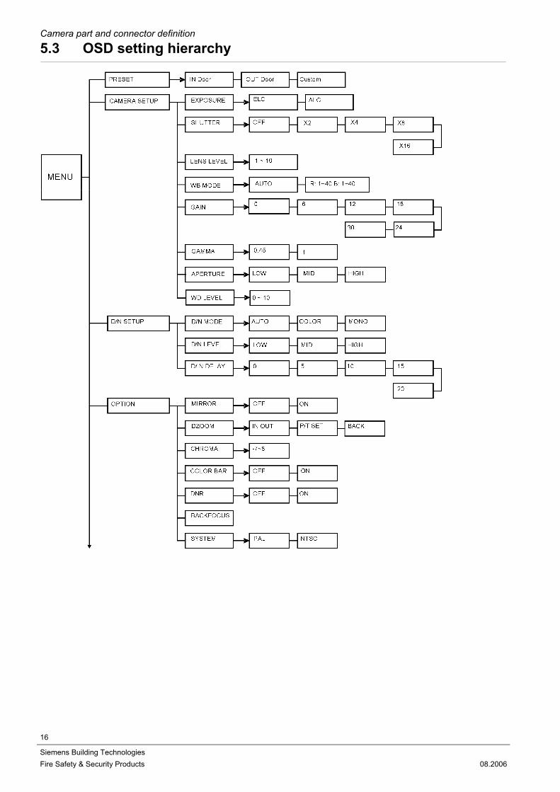
5.3 OSD setting hierarchy

Camera part and connector definition
17
Siemens Building Technologies Fire Safety & Security Products 08.2006

Install the camera
18
Siemens Building Technologies Fire Safety & Security Products 08.2006
6 Install the camera
6.1 Installation
1. Connect BNC cable to video output, please refer to chapter 5.1 Camera part definition.
2. Connect power source to power terminal. 3. To reduce radiation sufficiently, please wind one turn around the core, see
figure below. Location Core illustration Camera type Power cable
LX
Power cable
MX
Y/C cable
LX / MX
CAUTION If using a DC supply, make sure the polarity is correct. Incorrect connection may
cause malfunction and / or damage to the camera.
4. Adjust backfocus: The backfocus is adjusted in the factory for a CS mount lens as shipped, if re-adjust is necessary, please unlock screw. Enter Back Focus Format in OSD (please refer to chapter 6.2.4.8), then rotate backfocus wheel till a sharp image appears. Lock the screw tightly.
6.1.1 Using BNC composite video output
1. Connect BNC cable to video output, please refer to chapter 5.1 Camera part definition.
2. Make sure that a proper BNC 75 Ohm cable is used. 3. Switch on 75 Ohm termination in video receive equipment such as Monitor,
matrix or equivalent
6.1.2 Using twisted pair video output
1. Connect twisted pair cable to TP-Output of camera, please refer to chapter 5.1 Camera part definition
2. Connect suitable twisted pair receiver device (i.e. TP-RXMOD2) 3. Setup TP transmitter using DIP-switches, please refer to chapter 5.2.1. 4. Adjust twisted pair receiver to get best quality video-output, please refer to the
instruction manual of used twisted pair receiver

Install the camera
19
Siemens Building Technologies Fire Safety & Security Products 08.2006
6.2 Function settings
Press the ENTER of the OSD control button, the menu will appear on the display and will disappear after 30 seconds if no any action. The shaded setting area means an item selected and keeps blinking.
6.2.1 PRESET
Select PRESET function IN Door (2500 °K – 6500 °K), OUT Door (2500 °K – 9500 °K), or custom. This camera provides 2 kinds preset environ-ment settings. Which are IN Door and OUT Door, User can do fast setting in these 2 kinds environment parameter. OR, User can set envi-ronment parameter by self in custom mode. Using UP/DOWN key adjust cursor to PRESET as shown in the figure. Press ENTER key to enter modify mode, Using UP/DOWN key to select mode after selected and press ENTER key to leave modify mode.
6.2.2 CAMERA SETUP
Enter CAMERA SETUP submenu as shown in the figure. Using UP/DOWN key adjusts cursor to the item which wants to modify. Press ENTER key to enter modify status , Using UP/DOWN key to select Mode. After selected and then press ENTER key to leave modify Mode.
6.2.2.1 EXPOSURE
Setting ALC for Auto IRIS lens control or ELC for auto electronic shutter when using manual IRIS lens. Move the cursor to the position and push ENTER.
6.2.2.2 SHUTTER
Setting of slow electronic shutter (OFF to X 16).Move the cursor to the position as shown in the figure. Using the UP/ DOWN button, choose the slow shutter from OFF to X16.
MAIN MANU PRESET INROOM <CAMERA SETUP> <D/N SETUP> <OPTION> <OTHER SETUP> <REMOTE> <PRIVACY ZONE> BLC ZONE OFF SYNC MODE INT EXIT CANCEL DEFAULT
CAMERA SETUP EXPOSURE ALC SHUTTER OFF LENS LEVEL 5 WB MODE AUTO GAIN 24 GAMMA 0.45 APERTURE MID WD LEVEL 5 BACK
CAMERA SETUP EXPOSURE ALC SHUTTER OFF LENS LEVEL 5 WB MODE AUTO GAIN 24 GAMMA 0.45 APERTURE MID WD LEVEL 5 BACK

Install the camera
20
Siemens Building Technologies Fire Safety & Security Products 08.2006
6.2.2.3 LENS LEVEL
6.2.2.4 WB MODE
Selection and setting of the white balance sys-tem (AUTO and manual mode). Move the cursor to the position as shown in the figure. Using UP/ DOWN button to choose ATW or manual mode.
AUTO TTL auto trace white balance algorithm is de-signed to implement a perfect color reproduc-tion. Color temperature ranges are depending on preset mode.
Manual mode Press the ENTER button to enter manual mode. To obtain correct manual white balance adjust the R and B (red& blue) values by press UP, DOWN button. Press LEFT, RIGHT button to exit move cursor between R&B, and press ENTER button to exit.
6.2.2.5 GAIN
Adjust max. GAIN: 0 – 30 dB. Move the cursor to the position as shown in figure. Using UP/ DOWN button, choose gain value from 0 dB to 30 dB.
Setting the lens level (exposure level). Move the cursor to the position as shown in the figure. Push ENTER and use the UP/ DOWN button to select 1 - 10.
CAMERA SETUP EXPOSURE ALC SHUTTER OFF LENS LEVEL 5 WB MODE AUTO GAIN 24 GAMMA 0.45 APERTURE MID WD LEVEL 5 BACK
CAMERA SETUP EXPOSURE ALC SHUTTER OFF LENS LEVEL 5 WB MODE AUTO GAIN 24 GAMMA 0.45 APERTURE MID WD LEVEL 5 BACK
CAMERA SETUP EXPOSURE ALC SHUTTER OFF LENS LEVEL 5 WB MODE AUTO GAIN 24 GAMMA 0.45 APERTURE MID WD LEVEL 5 BACK

Install the camera
21
Siemens Building Technologies Fire Safety & Security Products 08.2006
6.2.2.6 GAMMA
0.45 or 1.0 can be selected Move the cursor to the position as shown in the figure to set GAMMA value. Generally, the default value 0.45 is used for CCTV monitor. For image processing purpose 1.0 can be selected.
6.2.2.7 APERTURE
Selection of picture sharpness. (LOW, MID, HIGH) Move the cursor to the position as shown in the figure. Use UP/ DOWN button, to choose HIGH, MID or LOW.
6.2.2.8 WD-LEVEL
Selection of the WD-threshold level. This setting increases/decreases the overall video bright-ness. Move the cursor to the position as shown in the figure. Use UP/DOWN button to choose from 0 to 10.
6.2.3 D/N SETUP
Enter D/N SETUP submenu as shown in the figure. Using UP/DOWN key to adjust cursor to the item which wants to modify. Press ENTER key to enter modify status. Using UP/DOWN key to select Mode. After selected and then press ENTER key to leave modify Mode.
CAMERA SETUP EXPOSURE ALC SHUTTER OFF LENS LEVEL 5 WB MODE AUTO GAIN 24 GAMMA 0.45 APERTURE MID WD LEVEL 5 BACK
CAMERA SETUP EXPOSURE ALC SHUTTER OFF LENS LEVEL 5 WB MODE AUTO GAIN 24 GAMMA 0.45 APERTURE MID WD LEVEL 5 BACK
CAMERA SETUP EXPOSURE ALC SHUTTER OFF LENS LEVEL 5 WB MODE AUTO GAIN 24 GAMMA 0.45 APERTURE MID WD LEVEL 5 BACK
D/N SETUP D/N MODE AUTO D/N LEVEL MID D/N DELAY 5 BACK
MAIN MANU PRESET INROOM <CAMERA SETUP> <D/N SETUP> <OPTION> <OTHER SETUP> <REMOTE> <PRIVACY ZONE> BLC ZONE OFF SYNC MODE INT EXIT CANCEL DEFAULT

Install the camera
22
Siemens Building Technologies Fire Safety & Security Products 08.2006
6.2.3.1 D/N MODE
Select Day/Night function automatically, color or mono. Move the cursor to the position as shown in the figure. Use the UP/ DOWN button to se-lect AUTO, MONO or COLOR mode.
AUTO: When set to this mode, the camera will change to COLOR mode or B/W mode auto-matically depending on a subject’s brightness.
MONO: When set to this mode, the camera will remain in monochrome mode always.
COLOR: When set to this mode, the camera will remain in COLOR always.
6.2.3.2 D/N LEVEL
Select filter switchover point High, Low or Mid-dle. Set up a switchover point from COLOR mode to B/W mode. Move the cursor to the position as shown in the figure. Use the UP/DOWN button to select HIGH, LOW or MID. The level only affects when the D/N mode set as AUTO.
A. LOW: The switchover point of gain from COLOR into B/W mode is 21 dB, and back to COLOR mode point is 18 dB.
B. MID: The switchover point of gain from COLOR into B/W mode is 22 dB, and back to COLOR mode point is 18 dB.
C. HIGH: The switchover point of gain from COLOR into B/W mode is 23 dB, and back to COLOR mode point is 18 dB.
6.2.3.3 D/N DELAY
Setting DELAY time for D/ N function. Move the cursor to the position as shown in the figure. Use the UP/ DOWN button to select 0, 5, 10, 15 or 20 sec for delay of into D/N mode timing. This function only affects when D/N Mode to be set as AUTO.
6.2.4 OPTION
Enter OPTION submenu as shown in the figure. Using UP/DOWN Key to adjust cursor to the function which wants to modify. Press ENTER key to enter Modify status and then using UP/DOWN key to select Mode after selected and then press Enter key to leave modify status.
D/N SETUP D/N MODE AUTO D/N LEVEL MID D/N DELAY 5 BACK
D/N SETUP D/N MODE AUTO D/N LEVEL MID D/N DELAY 5 BACK
D/N SETUP D/N MODE AUTO D/N LEVEL MID D/N DELAY 5 BACK
OPTION MIRROR OFF <DZOOM> CHROMA 3 COLOR BAR OFF DNR OFF <BACKFOCUS> SYSTEM PAL BACK
Install the camera
Siemens Building Technologies Fire Safety & Security Products
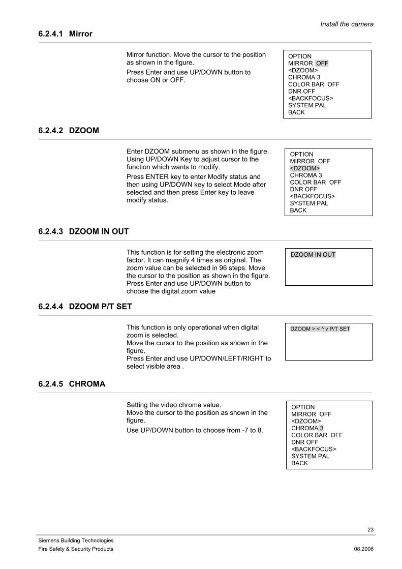
6.2.4.1 Mirror
Mirror function. Move the cursor to the position as shown in the figure. Press Enter and use UP/DOWN button to choose ON or OFF.
6.2.4.2 DZOOM
Enter DZOOM submenu as shown in the figure. Using UP/DOWN Key to adjust cursor to the function which wants to modify. Press ENTER key to enter Modify status and then using UP/DOWN key to select Mode after selected and then press Enter key to leave modify status.
6.2.4.3 DZOOM IN OUT
This function is for setting the electronic zoom factor. It can magnify 4 times as original. The zoom value can be selected in 96 steps. Move the cursor to the position as shown in the figure.Press Enter and use UP/DOWN button to choose the digital zoom value
6.2.4.4 DZOOM P/T SET
This function is only operational when digital zoom is selected. Move the cursor to the position as shown in the figure. Press Enter and use UP/DOWN/LEFT/RIGHT to select visible area .
6.2.4.5 CHROMA
Setting the video chroma value. Move the cursor to the position as shown in the figure. Use UP/DOWN button to choose from -7 to 8.
OPTION MIRROR OFF <DZOOM> CHROMA 3 COLOR BAR OFFDNR OFF <BACKFOCUS> SYSTEM PAL BACK
OPTION MIRROR OFF <DZOOM> CHROMA 3 COLOR BAR OFFDNR OFF <BACKFOCUS> SYSTEM PAL BACK
23
08.2006
DZOOM IN OUT
DZOOM > < ^ v P/T SET
OPTION MIRROR OFF <DZOOM> CHROMA 3 COLOR BAR OFF DNR OFF <BACKFOCUS> SYSTEM PAL BACK

Install the camera
24
Siemens Building Technologies Fire Safety & Security Products
6.2.4.6 COLOR BAR
6.2.4.7 DNR
This function is for digital noise reduce. Move the cursor to the position as shown in the figure.Press Enter and use UP/DOWN button to choose ON or OFF.
6.2.4.8 BACKFOCUS
This function is for perform back focus adjust. It will force the iris of the AI lens to open fully and set to ELC mode for easy back focus adjust-ment. Move the cursor to the position as shown in the figure. Press Enter and use UP/DOWN button to choose ON or OFF.
6.2.4.9 SYSTEM
Move the cursor to the position as shown in the figure. Press Enter Key and use UP/DOWN button to choose NTSC or PAL system.
6.2.5 OTHER SETUP
Enter OTHER SETUP submenu as shown in the figure. Using UP/DOWN Key to adjust cursor to the function which wants to modify. Press ENTER key to enter Modify status and then using UP/DOWN key to select Mode after selected and then press Enter key to leave modify status.
This function is present for test. Move the cursor to the position as shown in the figure. Press Enter and use UP/DOWN button to choose ON or OFF. The color bar as shown in the figure.
OPTION MIRROR OFF <DZOOM> CHROMA 3 COLOR BAR OFFDNR OFF <BACKFOCUS> SYSTEM PAL BACK
08.2006
OPTION MIRROR OFF <DZOOM> CHROMA 3 COLOR BAR OFF DNR OFF <BACKFOCUS> SYSTEM PAL BACK
OPTION MIRROR OFF <DZOOM> CHROMA 3 COLOR BAR OFF DNR OFF <BACKFOCUS> SYSTEM PAL BACK
OPTION MIRROR OFF <DZOOM> CHROMA 3 COLOR BAR OFF DNR OFF <BACKFOCUS> SYSTEM PAL BACK
OTHER SETUP CAMERA ID ----------------------------- <ALARM> <MOTION> BACK

Install the camera
Siemens Building Technologies Fire Safety & Security Products
6.2.5.1 CAMERA ID
Select the CAMERA ID position, press ENTER into modify mode as shown in the figure. Right button choose position and use UP/DOWN button choose text (0 - 9, A - Z) the max 24 characters.
6.2.5.2 ALARM
Enter ALARM submenu as shown in the figure. Using UP/DOWN Key to adjust cursor to the function which wants to modify. Press ENTER key to enter Modify status and then using UP/DOWN key to select Mode after selected and then press Enter key to leave modify status.
6.2.5.3 ALARM TEXT
Select the ALARM TEXT position, press ENTER into modify mode as shown in the figure. Using Left/Right button choose position and use UP/DOWN button choose text (0 - 9, A - Z) the max 24 characters.
6.2.5.4 ALARM ACTION
Use the UP/DOWN button to select OFF, OUT, B/W, ALL (OUT & B/W) as shown in the figure.
6.2.5.5 ALARM DELAY
Use the UP/DOWN button to select 0, 5, 10, 15, 20 sec. For delay of ALARM operate timing as shown in the figure. Alarm will be reset auto-matically after selected time.
OTHER SETUP CAMERA ID ----------------------------- <ALARM> <MOTION> BACK
ALARM TEXT ---------------------------------- ALARM ACTION OUT ALARM DELAY 0 BACK
ALARM TEXT ---------------------------------- ALARM ACTION OUT ALARM DELAY 0 BACK
OTHER SETUP CAMERA ID ----------------------------- <ALARM> <MOTION> BACK
25
08.2006
ALARM TEXT ---------------------------------- ALARM ACTION OUT ALARM DELAY 0 BACK

Install the camera
26
Siemens Building Technologies Fire Safety & Security Products
6.2.5.6 MOTION
Enter MOTION submenu as shown in the figure. Using UP/DOWN Key to adjust cursor to the function which wants to modify. Press ENTER key to enter Modify status and then using UP/DOWN key to select Mode after selected and then press Enter key to leave modify status.
When MOTION set ON and image has bigger Change. It will trigger alarm. Enter MOTION item as shown in the figure. Press ENTER key to enter Modify status and then using UP/DOWN key to Select Mode ON OR OFF after selected and then press Enter key to Leave modify status.
6.2.5.7 MOTION LEVEL
Setting the motion detect sensitivity. Use the UP/DOWN keys to set the sensitivity in the range of 0 to 255. The value "0" corresponds to the highest sensitivity.
6.2.5.8 MOTION AREA
Enter MOTION AREA submenu as shown in the figure. Using UP/DOWN Key to adjust cursor to the function which wants to modify. Press ENTER key to enter Modify status and then using UP/DOWN key to select Mode after selected and then press Enter key to leave modify status.
6.2.5.9 SET ZONE POSI
Setting the alarm zone position.
6.2.5.10 SET ZONE SIZE
Changing the alarm zone size.
OTHER SETUP CAMERA ID ----------------------------- <ALARM> <MOTION> BACK
MOTION OFF MOTION LEVEL LOW <MOTION AREA> MOTION TEXT ------------------------------ ALARM OUT OFF MOTION DELAY 5 BACK
08.2006
MOTION OFF MOTION LEVEL LOW <MOTION AREA> MOTION TEXT ------------------------------ ALARM OUT OFF MOTION DELAY 5 BACK
MOTION OFF MOTION LEVEL 15 <MOTION AREA> MOTION TEXT ------------------------------ ALARM OUT OFF MOTION DELAY 5 BACK
SET ZONE > < ^ v POSI
SET ZONE > < ^ v SIZE

Install the camera
27
Siemens Building Technologies Fire Safety & Security Products 08.2006
6.2.5.11 SET ZONE MOVE
Moving the alarm zone position.
6.2.5.12 MOTION TEXT
Select the Motion TEXT position, press ENTER into modify mode as shown in the figure. Using Left/Right button choose position and use UP/DOWN button choose text (0 - 9, A - Z) the max 24 characters.
6.2.5.13 ALARM OUT
Use the UP/DOWN button to select 0, 5, 10, 15, 20 sec. For delay of ALARM operate timing as shown in the figure.
6.2.5.14 MOTION DELAY
Use the UP/DOWN button to select 0, 5, 10, 15, 20 sec. For delay of Motion ALARM operate timing as shown in the figure. Alarm will be re-set automatically after selected time
MOTION OFF MOTION LEVEL LOW <MOTION AREA> MOTION TEXT ------------------------------ ALARM OUT OFF MOTION DELAY 5 BACK
MOTION OFF MOTION LEVEL LOW <MOTION AREA> MOTION TEXT ------------------------------ ALARM OUT OFF MOTION DELAY 5 BACK
MOTION OFF MOTION LEVEL LOW <MOTION AREA> MOTION TEXT ------------------------------ ALARM OUT OFF MOTION DELAY 5 BACK
SET ZONE > < ^ v MOVE

Install the camera
28
Siemens Building Technologies Fire Safety & Security Products 08.2006
6.2.6 REMOTE
Enter REMOTE submenu as shown in the fig-ure. Using UP/DOWN Key to adjust cursor to the function which wants to Modify. Press ENTER key to enter Modify status and then using UP/DOWN key to select Mode after selected and then press Enter key to leave modify status.
6.2.6.1 ADDRESS
Setup camera address volume 0 – 255.
6.2.6.2 PROTOCOL
Protocol include Siemens-U, Siemens-B, Siemens-S and MOLYNX-D.
6.2.6.3 BAUD RATE
Baud Rate: 2400, 4800, 9600, 19200.
6.2.7 PRIVACY ZONE
Move the cursor to the position as shown in the figure. Press ENTER to turn on the privacy zone mode, than use UP/DOWN and Left/Right button to setting zone position, when ok press ENTER and use UP/DOWN and Left/Right button to setting zone size and press ENTER to leave this function.
REMOTE ADDRESS 1 PROTOCOL SIEMENS-B BAUD RATE 4800 BACK DEFAULT
MAIN MANU PRESET INROOM <CAMERA SETUP> <D/N SETUP> <OPTION> <OTHER SETUP> <REMOTE> <PRIVACY ZONE> BLC ZONE OFF SYNC MODE INT EXIT CANCEL DEFAULT

Install the camera
29
Siemens Building Technologies Fire Safety & Security Products 08.2006
6.2.8 BLC ZONE
Selection of backlight mode. Move the cursor to the position as shown in the figure. Push Enter and using UP / DOWN button to choose OFF, CENTER 1, CENTER 2, UP Half, LOW half, Door Low or Door High. (The BLC area will not display on screen.) A. OFF: The BLC function is off.
B. CENTER 1: Backlight compensation window is like.
C. CENTER 2: Backlight compensation window is like.
D. UP Half: Backlight compensation window is like .
E. LOW half: Backlight compensation window is like.
F: Door Low: Backlight compensation window is like.
G: Door High: Backlight compensation window is like .
MAIN MANU PRESET INROOM <CAMERA SETUP> <D/N SETUP> <OPTION> <OTHER SETUP> <REMOTE> <PRIVACY ZONE> BLC ZONE OFF SYNC MODE INT EXIT CANCEL DEFAULT
Install the camera
30
Siemens Building Technologies Fire Safety & Security Products 08.2006
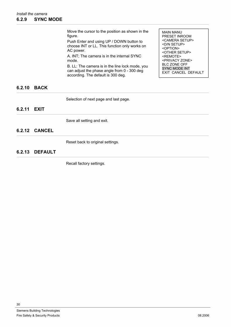
6.2.9 SYNC MODE
Move the cursor to the position as shown in the figure. Push Enter and using UP / DOWN button to choose INT or LL. This function only works on AC power. A. INT; The camera is in the internal SYNC mode. B. LL: The camera is in the line lock mode, you can adjust the phase angle from 0 - 300 deg according. The default is 300 deg.
6.2.10 BACK
Selection of next page and last page.
6.2.11 EXIT
Save all setting and exit.
6.2.12 CANCEL
Reset back to original settings.
6.2.13 DEFAULT
Recall factory settings.
MAIN MANU PRESET INROOM <CAMERA SETUP> <D/N SETUP> <OPTION> <OTHER SETUP> <REMOTE> <PRIVACY ZONE> BLC ZONE OFF SYNC MODE INT EXIT CANCEL DEFAULT

Maintenance
31
Siemens Building Technologies Fire Safety & Security Products 08.2006
7 Maintenance
Defective modules should be sent to the nearest Siemens office to be forwarded to the service centre.
8 Disposal
All electrical and electronic products should be disposed of separately from the municipal waste stream via designated collection facilities appointed by the government or the local authorities. This crossed-out wheeled bin symbol on the product means the product is covered by the European Directive 2002/96/EC. The correct disposal and separate collection of your old appliance will help prevent potential negative consequences for the environment and human health. It is a precondition for reuse and recycling of used electrical and electronic equipment. For more detailed information about disposal of your old appliance, please contact your city office, waste disposal service or the shop where you purchased the product.
Keyword index
32
Siemens Building Technologies Fire Safety & Security Products 08.2006
9 Keyword index
A ADDRESS 28 ALARM ACTION 25 ALARM DELAY 25, 27 ALARM TEXT 25, 27 APERTURE 21
B BACK 30 BACKFOCUS 24 BAUD RATE 28 BLC ZONE 29
C CAMERA ID 25 Camera part 13, 18 CAMERA SETUP 19 CANCEL 30 CHROMA 23 Cleaning 9 CMOS Characteristics 9 COLOR BAR 24
D D/N DELAY 22 D/N LEVEL 22 D/N MODE 22 D/N SETUP 21 DEFAULT 30 Dimensions 10 DNR 24 DZOOM 23
E EXIT 30 EXPOSURE 19
F Function setting 19
G GAIN 20 GAMMA 21 General guidelines 7
L LENS LEVEL 20
M Mirror 23 MOTION 26 MOTION LEVEL 26, 27
O Operation and storage 9 OPTION 22 Ordering data 12 OTHER SETUP 24
P Package contents 12 Pin definiton 14 PRESET 19 PRIVACY ZONE 28 Product specifications 10 PROTOCOL 28
R REMOTE 28
S Safety precautions 5 SHUTTER 19 SYNC MODE 30 SYSTEM 24
T Transportation 9
W WB MODE 20

33
Siemens Building Technologies Fire Safety & Security Products 08.2006

Issued by Siemens Building Technologies Fire & Security Products GmbH & Co. oHG D-76181 Karlsruhe www.sbt.siemens.com
© 2006 Copyright bySiemens Building Technologies AG
Data and design subject to change without notice.Supply subject to availability.
Printed in the Federal Republic of Germany on environment-friendly chlorine-free paper.
Document no. A24205-A336-B315 Edition 08.2006


