EMS Educational Material_001 13. The signal check of Vehicle Speed Sensor 1. Troubles 1. Malfunction of vehicle speed sensor Cause of trouble 1.1 Malfunction of vehicle speed sensor or wiring circuit failure(Signal, Ground line) Cause of trouble 1.1 Replace vehicle speed sensor 1.2 Bad connecting of vehicle speed sensor signal line or short to battery or ground Engine state RPM floating and cycling is occurred in idle sate. Signal measure ment 2. Occurrence of over speed Cause of trouble 2.1 Noise occurrence in vehicle speed signal a. Noise detection from TCU connecting line b. Noise detection from ignition system Cause of trouble 2.1 Shield wiring of vehicle speed sensor and connect directly with single line. Engine state RPM floating and cycling is occurred in idle sate. In case of manual transmission, surging may be detected with fast acceleration and in case of auto, poor acceleration is occurred with low vehicle speed and high gear shift. Signal measure ment 13_Vehicle Speed Sensor 1/13
Transcript
EMS Educational Material_001
13. The signal check of Vehicle Speed Sensor 1. Troubles
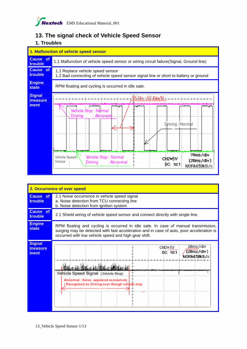
1. Malfunction of vehicle speed sensor
Cause of trouble 1.1 Malfunction of vehicle speed sensor or wiring circuit failure(Signal, Ground line)
Cause of trouble
1.1 Replace vehicle speed sensor 1.2 Bad connecting of vehicle speed sensor signal line or short to battery or ground
Engine state RPM floating and cycling is occurred in idle sate.
Signal measurement
2. Occurrence of over speed
Cause of trouble
2.1 Noise occurrence in vehicle speed signal a. Noise detection from TCU connecting line b. Noise detection from ignition system
Cause of trouble 2.1 Shield wiring of vehicle speed sensor and connect directly with single line.
Engine state RPM floating and cycling is occurred in idle sate. In case of manual transmission,
surging may be detected with fast acceleration and in case of auto, poor acceleration is occurred with low vehicle speed and high gear shift.
Signal measurement
13_Vehicle Speed Sensor 1/13
EMS Educational Material_001
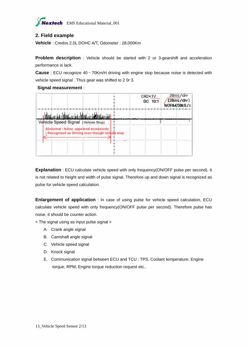
2. Field example Vehicle : Credos 2.0L DOHC A/T, Odometer : 28,000Km
Problem description : Vehicle should be started with 2 or 3-gearshift and acceleration
performance is lack.
Cause : ECU recognize 40∼70Km/H driving with engine stop because noise is detected with
vehicle speed signal . Thus gear was shifted to 2 0r 3.
Signal measurement :
Explanation : ECU calculate vehicle speed with only frequency(ON/OFF pulse per second). It
is not related to height and width of pulse signal. Therefore up and down signal is recognized as
pulse for vehicle speed calculation.
Enlargement of application : In case of using pulse for vehicle speed calculation, ECU
calculate vehicle speed with only frequency(ON/OFF pulse per second). Therefore pulse has
noise, it should be counter action.
< The signal using as input pulse signal >
A. Crank angle signal
B. Camshaft angle signal
C. Vehicle speed signal
D. Knock signal
E. Communication signal between ECU and TCU : TPS, Coolant temperature, Engine
4. Check method Explain the checking Method and Diagnosis of trouble.. Preparation 1. 1. Oscilloscope (It prefers not to use Multimeter )
2. 2. Wiring diagram of vehicle speed sensor. 3. Scanner
1. 1. Find and connect the Signal and Ground line referencing the wiring diagram. 2. 2. Check How the Signal voltage is with connecting the Oscilloscope. 3. 3. Because it is difficult to measure the vehicle speed on driving, make the vehicle lock the rear
wheels and lift the front wheels. And then engage the gear and declutch. At this time, let’s reference that the vehicle speed displayed on Meter set is half of real speed due to mechanism of differential gear.
< Reference > In case of connecting the Multimeter, It prefers not to use multimeter because it is difficult to measure the vehicle speed signal, which continue ON/OFF fast. < Reference > In case of connecting the Auto-Scanner, Let’s reference the results because Auto-scanner diagnoses some vehicle speed signal’s troubles automatically. Comparing Method: After measuring the signal, compare the measured signal with Normal signal.
(1) Compare the current measured vehicle speed signal and frequency with that of normal condition. (2) It would like to check the Battery voltage with connecting the scanner if possible.
< Checking items > (1) Whether the scanner recognizes the vehicle speed though vehicle stop. (2) Whether the noise is occurring in the vehicle speed signal. (3) Whether the ON/OFF level of vehicle speed signal is not changed on driving.
Check method < After inserting the Picture which measuring the signal of Vehicle speed sensor, Write the Explanation about wiring. >
13_Vehicle Speed Sensor 4/13
EMS Educational Material_001
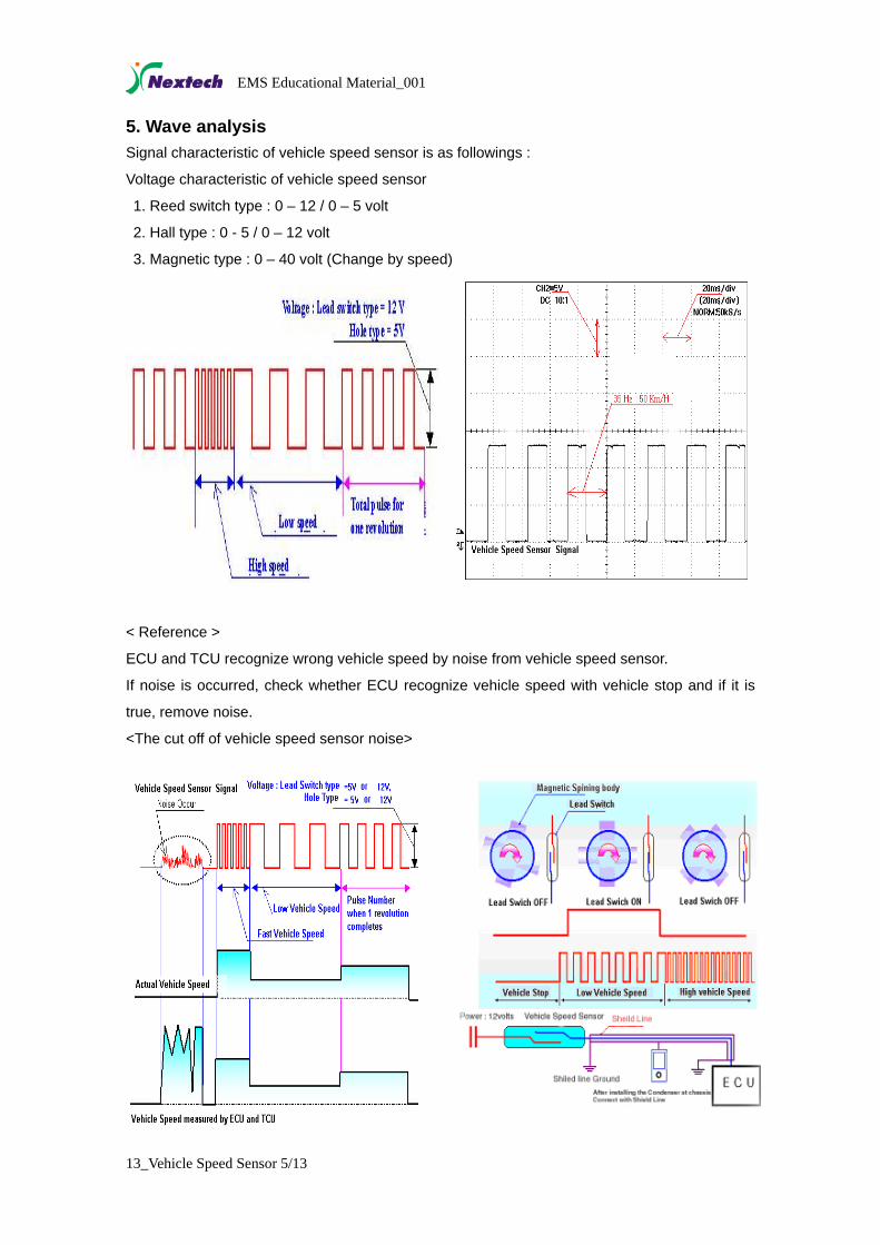
5. Wave analysis Signal characteristic of vehicle speed sensor is as followings :
Voltage characteristic of vehicle speed sensor
1. Reed switch type : 0 – 12 / 0 – 5 volt
2. Hall type : 0 - 5 / 0 – 12 volt
3. Magnetic type : 0 – 40 volt (Change by speed)
< Reference >
ECU and TCU recognize wrong vehicle speed by noise from vehicle speed sensor.
If noise is occurred, check whether ECU recognize vehicle speed with vehicle stop and if it is
true, remove noise.
<The cut off of vehicle speed sensor noise>
13_Vehicle Speed Sensor 5/13
EMS Educational Material_001
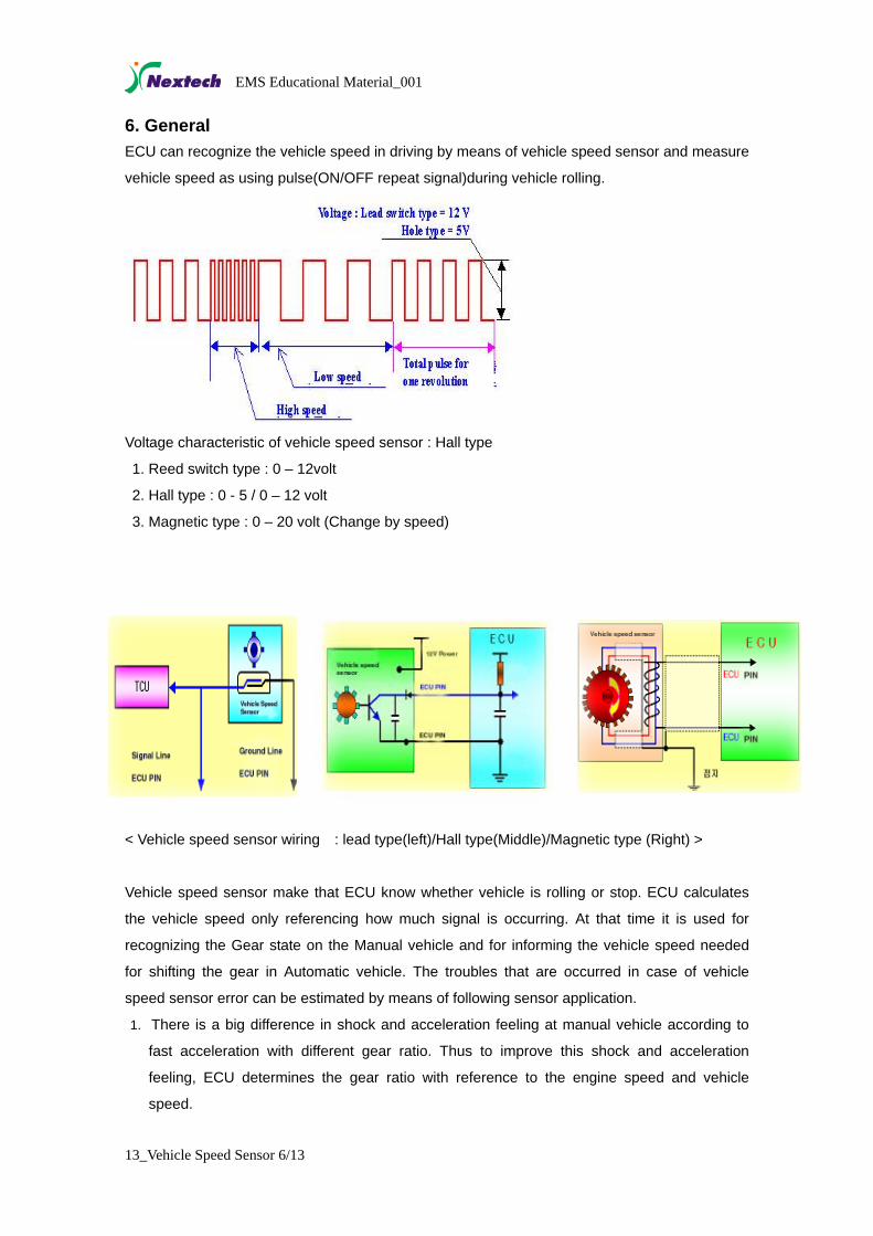
6. General ECU can recognize the vehicle speed in driving by means of vehicle speed sensor and measure
vehicle speed as using pulse(ON/OFF repeat signal)during vehicle rolling.
Voltage characteristic of vehicle speed sensor : Hall type
1. Reed switch type : 0 – 12volt
2. Hall type : 0 - 5 / 0 – 12 volt
3. Magnetic type : 0 – 20 volt (Change by speed)
< Vehicle speed sensor wiring : lead type(left)/Hall type(Middle)/Magnetic type (Right) >
Vehicle speed sensor make that ECU know whether vehicle is rolling or stop. ECU calculates
the vehicle speed only referencing how much signal is occurring. At that time it is used for
recognizing the Gear state on the Manual vehicle and for informing the vehicle speed needed
for shifting the gear in Automatic vehicle. The troubles that are occurred in case of vehicle
speed sensor error can be estimated by means of following sensor application.
1. There is a big difference in shock and acceleration feeling at manual vehicle according to
fast acceleration with different gear ratio. Thus to improve this shock and acceleration
feeling, ECU determines the gear ratio with reference to the engine speed and vehicle
speed.
13_Vehicle Speed Sensor 6/13
EMS Educational Material_001
2. In automatic vehicle, gear ratio is determined with reference to the position of acceleration
pedal and the vehicle speed at that time.
< Reference > In case of above sensor application
1. If there is a misdetection of driving though vehicle is stop, engine irregularity (bad
condition) is occurred in idle state. On the contrary, if there is misdetection of vehicle stop
though driving, severe irregularity and engine stall is occurred.
There can be bad acceleration feeling and shock from misdetection of gear ratio caused by the
misdetection of vehicle speed. If vehicle speed is not determined exactly, gearshift come to be
fast or slow
13_Vehicle Speed Sensor 7/13
EMS Educational Material_001
7. Principle (Algorithm) introduction 7.1 Function of vehicle speed sensor 1) Distinguish vehicle running or not. Vehicle running(ROLL = OFF) or stop(ROLL=OFF) is determined by vehicle speed signal.
Vehicle is running with signal and stop with no signal.
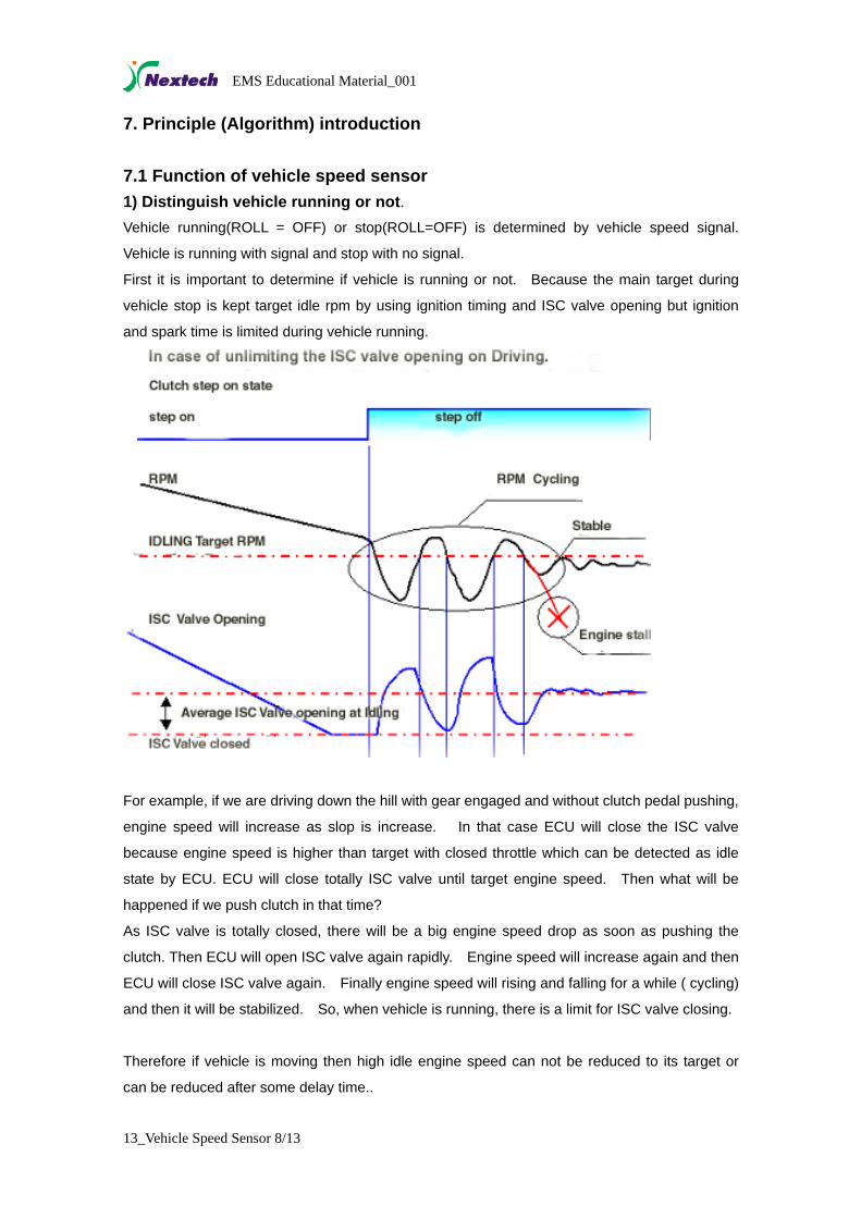
First it is important to determine if vehicle is running or not. Because the main target during
vehicle stop is kept target idle rpm by using ignition timing and ISC valve opening but ignition
and spark time is limited during vehicle running.
For example, if we are driving down the hill with gear engaged and without clutch pedal pushing,
engine speed will increase as slop is increase. In that case ECU will close the ISC valve
because engine speed is higher than target with closed throttle which can be detected as idle
state by ECU. ECU will close totally ISC valve until target engine speed. Then what will be
happened if we push clutch in that time?
As ISC valve is totally closed, there will be a big engine speed drop as soon as pushing the
clutch. Then ECU will open ISC valve again rapidly. Engine speed will increase again and then
ECU will close ISC valve again. Finally engine speed will rising and falling for a while ( cycling)
and then it will be stabilized. So, when vehicle is running, there is a limit for ISC valve closing.
Therefore if vehicle is moving then high idle engine speed can not be reduced to its target or
can be reduced after some delay time..
13_Vehicle Speed Sensor 8/13
EMS Educational Material_001
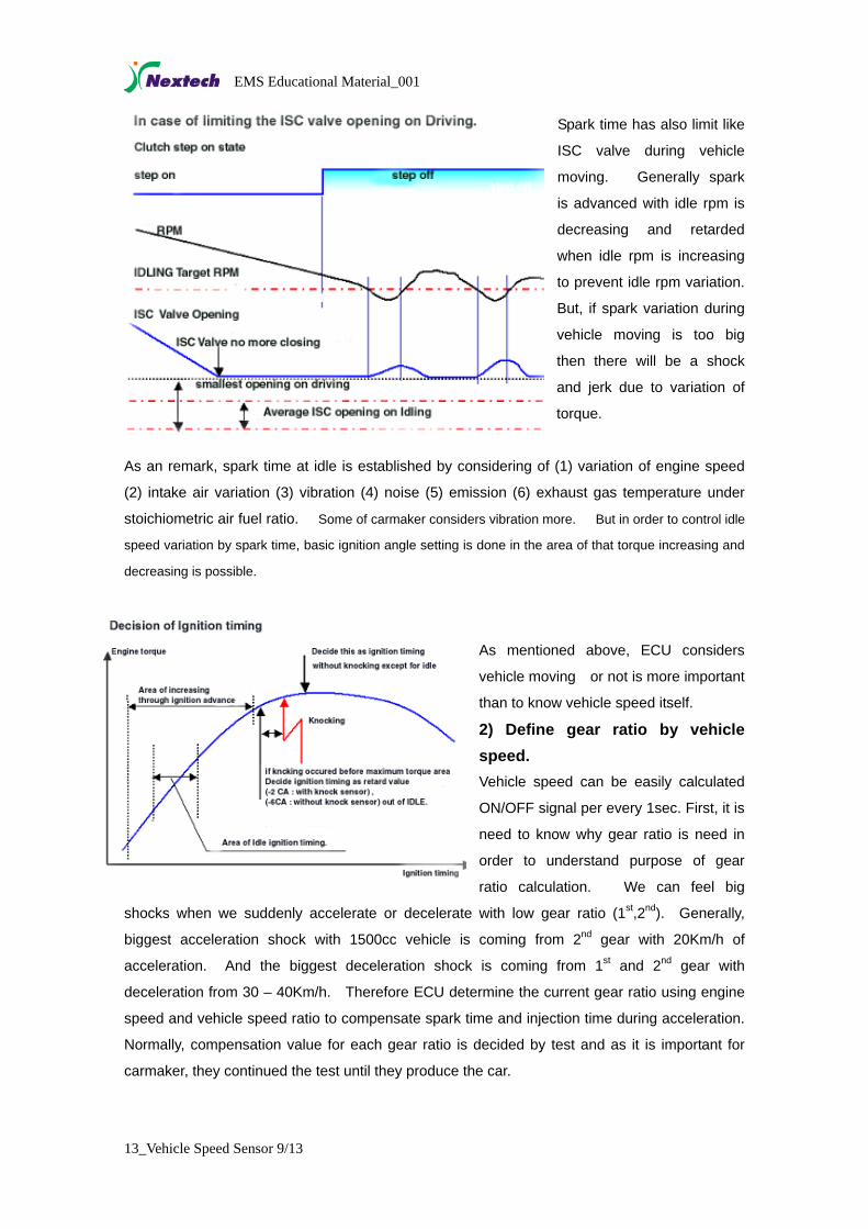
Spark time has also limit like
ISC valve during vehicle
moving. Generally spark
is advanced with idle rpm is
decreasing and retarded
when idle rpm is increasing
to prevent idle rpm variation.
But, if spark variation during
vehicle moving is too big
then there will be a shock
and jerk due to variation of
torque.
As an remark, spark time at idle is established by considering of (1) variation of engine speed
(2) intake air variation (3) vibration (4) noise (5) emission (6) exhaust gas temperature under
stoichiometric air fuel ratio. Some of carmaker considers vibration more. But in order to control idle
speed variation by spark time, basic ignition angle setting is done in the area of that torque increasing and
decreasing is possible.
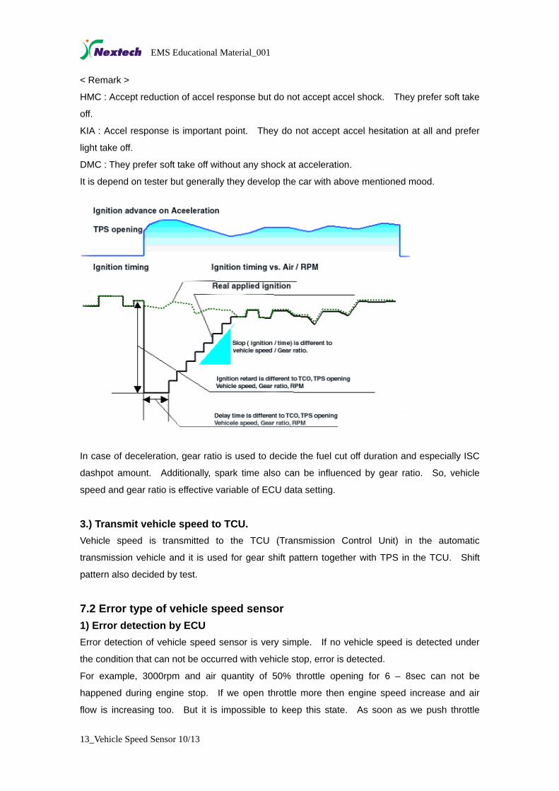
As mentioned above, ECU considers
vehicle moving or not is more important
than to know vehicle speed itself.
2) Define gear ratio by vehicle speed. Vehicle speed can be easily calculated
ON/OFF signal per every 1sec. First, it is
need to know why gear ratio is need in
order to understand purpose of gear
ratio calculation. We can feel big
shocks when we suddenly accelerate or decelerate with low gear ratio (1st,2nd). Generally,
biggest acceleration shock with 1500cc vehicle is coming from 2nd gear with 20Km/h of
acceleration. And the biggest deceleration shock is coming from 1st and 2nd gear with
deceleration from 30 – 40Km/h. Therefore ECU determine the current gear ratio using engine
speed and vehicle speed ratio to compensate spark time and injection time during acceleration.
Normally, compensation value for each gear ratio is decided by test and as it is important for
carmaker, they continued the test until they produce the car.
13_Vehicle Speed Sensor 9/13
EMS Educational Material_001
< Remark >
HMC : Accept reduction of accel response but do not accept accel shock. They prefer soft take
off.
KIA : Accel response is important point. They do not accept accel hesitation at all and prefer
light take off.
DMC : They prefer soft take off without any shock at acceleration.
It is depend on tester but generally they develop the car with above mentioned mood.
In case of deceleration, gear ratio is used to decide the fuel cut off duration and especially ISC
dashpot amount. Additionally, spark time also can be influenced by gear ratio. So, vehicle
speed and gear ratio is effective variable of ECU data setting.
3.) Transmit vehicle speed to TCU.
Vehicle speed is transmitted to the TCU (Transmission Control Unit) in the automatic
transmission vehicle and it is used for gear shift pattern together with TPS in the TCU. Shift
pattern also decided by test.
7.2 Error type of vehicle speed sensor 1) Error detection by ECU Error detection of vehicle speed sensor is very simple. If no vehicle speed is detected under
the condition that can not be occurred with vehicle stop, error is detected.
For example, 3000rpm and air quantity of 50% throttle opening for 6 – 8sec can not be
happened during engine stop. If we open throttle more then engine speed increase and air
flow is increasing too. But it is impossible to keep this state. As soon as we push throttle
13_Vehicle Speed Sensor 10/13
EMS Educational Material_001
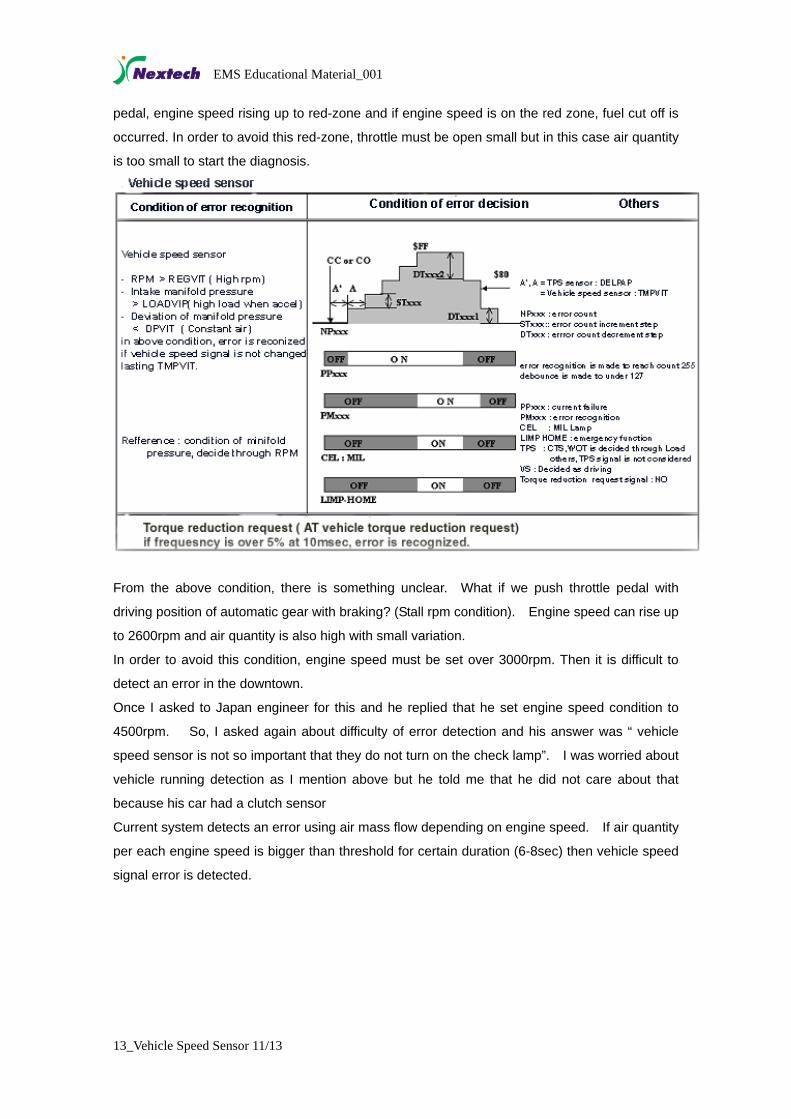
pedal, engine speed rising up to red-zone and if engine speed is on the red zone, fuel cut off is
occurred. In order to avoid this red-zone, throttle must be open small but in this case air quantity
is too small to start the diagnosis.
From the above condition, there is something unclear. What if we push throttle pedal with
driving position of automatic gear with braking? (Stall rpm condition). Engine speed can rise up
to 2600rpm and air quantity is also high with small variation.
In order to avoid this condition, engine speed must be set over 3000rpm. Then it is difficult to
detect an error in the downtown.
Once I asked to Japan engineer for this and he replied that he set engine speed condition to
4500rpm. So, I asked again about difficulty of error detection and his answer was “ vehicle
speed sensor is not so important that they do not turn on the check lamp”. I was worried about
vehicle running detection as I mention above but he told me that he did not care about that
because his car had a clutch sensor
Current system detects an error using air mass flow depending on engine speed. If air quantity
per each engine speed is bigger than threshold for certain duration (6-8sec) then vehicle speed
signal error is detected.
13_Vehicle Speed Sensor 11/13
EMS Educational Material_001
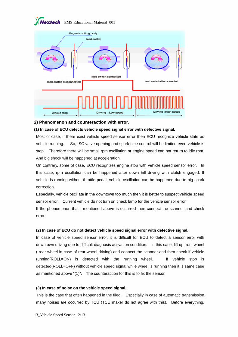
2) Phenomenon and counteraction with error. (1) In case of ECU detects vehicle speed signal error with defective signal.
Most of case, if there exist vehicle speed sensor error then ECU recognize vehicle state as
vehicle running. So, ISC valve opening and spark time control will be limited even vehicle is
stop. Therefore there will be small rpm oscillation or engine speed can not return to idle rpm.
And big shock will be happened at acceleration.
On contrary, some of case, ECU recognizes engine stop with vehicle speed sensor error. In
this case, rpm oscillation can be happened after down hill driving with clutch engaged. If
vehicle is running without throttle pedal, vehicle oscillation can be happened due to big spark
correction.
Especially, vehicle oscillate in the downtown too much then it is better to suspect vehicle speed
sensor error. Current vehicle do not turn on check lamp for the vehicle sensor error,
If the phenomenon that I mentioned above is occurred then connect the scanner and check
error.
(2) In case of ECU do not detect vehicle speed signal error with defective signal.
In case of vehicle speed sensor error, it is difficult for ECU to detect a sensor error with
downtown driving due to difficult diagnosis activation condition. In this case, lift up front wheel
( rear wheel in case of rear wheel driving) and connect the scanner and then check if vehicle
running(ROLL=ON) is detected with the running wheel. If vehicle stop is
detected(ROLL=OFF) without vehicle speed signal while wheel is running then it is same case
as mentioned above “(1)”. The counteraction for this is to fix the sensor.
(3) In case of noise on the vehicle speed signal.
This is the case that often happened in the filed. Especially in case of automatic transmission,
many noises are occurred by TCU (TCU maker do not agree with this). Before everything,
13_Vehicle Speed Sensor 12/13
EMS Educational Material_001
13_Vehicle Speed Sensor 13/13
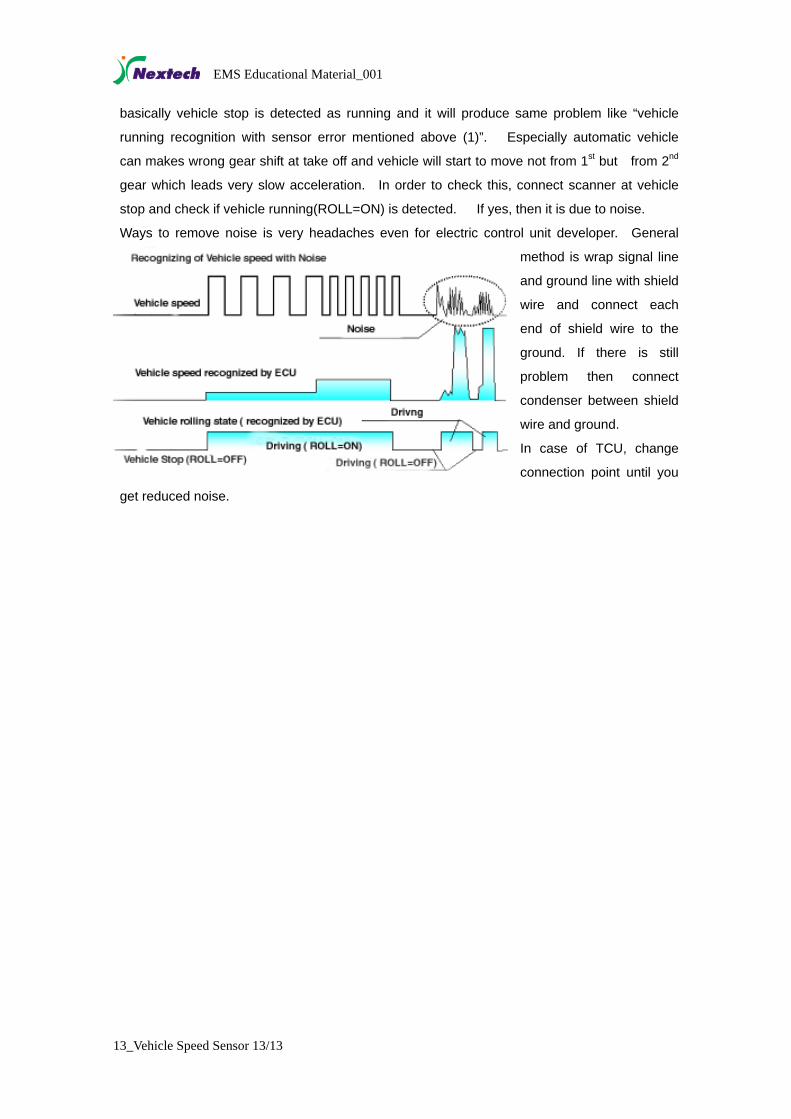
basically vehicle stop is detected as running and it will produce same problem like “vehicle
running recognition with sensor error mentioned above (1)”. Especially automatic vehicle
can makes wrong gear shift at take off and vehicle will start to move not from 1st but from 2nd
gear which leads very slow acceleration. In order to check this, connect scanner at vehicle
stop and check if vehicle running(ROLL=ON) is detected. If yes, then it is due to noise.
Ways to remove noise is very headaches even for electric control unit developer. General