The purpose of this manual is to provide the user with ageneral description of the theory, operation, installationset-up and maintenance of an IPS-400 or IPS-800, In-PlantPersonnel Warning System.
This manual contains information proprietary to WhelenEngineering Company, Inc. Any reproduction of thismanual is expressly prohibited except as WhelenEngineering Company, Inc. may otherwise agree to inwriting.
Whelen Engineering Company, Inc. reserves the right torevise and improve its product as it sees fit.
Manual # 04-0113276-00Cwas # 04-0115924-01C
Copyright 1996 Whelen Engineering Company, Inc.All rights reserved. 13276
1.0 Introduction to the IPS ......................................................................................................21.1 Using This Manual ...........................................................................................................2
4.0 IPS Module Descriptions...................................................................................................64.1 ESC-864 (Controller)........................................................................................................64.1.1 Local Controls and LED Indicators ...................................................................................64.1.2 ESC-864 Controller Circuit Board....................................................................................94.1.3 Tone Generator .................................................................................................................94.1.4 Digital Voice (option) .......................................................................................................94.1.5 Landline or RF Link Interfaces (options)...........................................................................94.1.6 DTMF Formats .................................................................................................................94.1.7 Radio Receiver/Transceiver (option)...............................................................................114.1.8 Local Microphone Input and Volume Control .................................................................114.1.9 System Diagnostics .........................................................................................................114.2 Power Amplifier Operation .............................................................................................114.2.1 Speaker Configurations...................................................................................................124.3 System Driver Board.......................................................................................................134.3.1 Audio Signal Distribution ...............................................................................................134.3.2 IPS Silent Test Operation................................................................................................134.3.3 Power Saving Logic ........................................................................................................144.3.4 DC Voltage Regulation ...................................................................................................144.4 Battery Charger Operation ..............................................................................................144.5 Batteries..........................................................................................................................14
5.0 Installation Instructions...................................................................................................155.1 Site Selection ..................................................................................................................155.2 Receiving/Unpacking the IPS..........................................................................................175.3 Installation of the IPS Cabinet.........................................................................................175.3a Installation of the “Type C” Cabinet................................................................................185.4 Conduit Openings for the IPS Cabinet.............................................................................195.5 AC Wiring......................................................................................................................205.6 Speaker Wiring...............................................................................................................215.7 Radio Option...................................................................................................................22
Information on the operation, installation, and maintenance of the Whelen Engineering Company’s In-Plant PersonnelWarning System (IPS) is provided in this technical manual. The IPS-400 and the IPS-800 are essentially the same. TheIPS- 400 has a single 400 watt amplifier, while the IPS-800 has two. This means that the IPS-800 can drive 800 watts ofaudio power versus 400 watts for the IPS-400. The IPS-800 also has more battery capacity than the IPS-400. In themajority of cases throughout this manual, all IPS models will be referred to as an IPS.
The IPS is a complex system, capable of generating six standard warning signals and Public Address (PA). The IPS canoperate with various combinations of speakers. The IPS may be linked to a central control point or points via radiofrequency (RF) or landline (telephone circuit, dry contact or dual tone multifrequency via twisted pair), permittingmultiplexed control and status feedback.
A typical In-Plant System consists of a Control Cabinet, with an ESC-864 Controller, 1 or 2 Power Amplifiers, a SystemDriver Board, a Battery Charger and Batteries. In addition, a system may include some number of various types ofspeakers.
1.1 Using This Manual
This manual is divided into a number of sections. Much of the discussion relates to generic Whelen EngineeringCompany, Inc. siren operation, which is consistent with other Whelen products, like the WPS-2800 Series. Since everyIPS system has a control cabinet, it is covered in the most detail. Optional system components, such as; speakers orstrobes are discussed in individual sections or in separate Product Description sheets.
3
Section 2 IPS CONTROLLER DESCRIPTION
2.0 Controller System Description
This section provides a general description of the IPS siren controller, including a physical description and a functionaldescription of the system. The functional description includes system activation methods, timing selection, signal andaudio characteristics, and power requirements.
2.1 Physical Description
The IPS is housed in an aluminum cabinet having two compartments. Each compartment has a raised, rolled lip alongits perimeter, and each compartment has a fully gasketed door. The lower compartment houses two Gel type batteries.An IPS-400 is equipped with two, 31 Ampere Hour batteries; an IPS-800 has two, 55 AH batteries. The uppercompartment contains the electronic modules, such as the ESC-864 Controller and Tone Generator, the PowerAmplifiers, the Battery Charger and the System Driver Board.
The modules are described in detail in Section 4.
SYSTEM DRIVER BOARD
BATTERY CHARGER
BATTERIES (31 AMP-HOUR AS SHOWN)
CONTROLLER
4
2.2 Operational Description
As previously mentioned, the IPS is a self-contained, microprocessor-controlled warning system capable of generatingsix standard siren warning signals, public address broadcast, and strobe light signaling. The standard warning signals--WAIL, ALERT, ATTACK, AIR HORN, HI/LO, AND WHOOP--are described in detail in Section 4.1.1.
The IPS is powered by a 115 VAC, 1.5 Amp service. A battery charger maintains two, 12 VDC, Gel type batteries, wiredin series, at an optimum charge level. The IPS actually operates from the 24 volts provided by the batteries. Fully chargedbatteries will run an IPS for at least thirty minutes.
2.2.1 System Activation/Control Methods
The IPS may be controlled through local or remote means, as follows:
Local Control. Pushbuttons on the front panel, of the ESC-864, provide immediate activation of warning tones, publicaddress and SI TEST®. A microphone, for PA announcements, may be plugged into the microphone jack on thecontroller front panel. Detailed descriptions of each control on the front panel of the ESC-864 is provided in Section4.1.1.
Remote Control. Remote control of an IPS may be accomplished by landline or radio transmission. The standardcommunication protocol is a ten digit DTMF (dual tone multi frequency) format. For landline control, an encoder isrequired at a central control point. For radio transmission, an encoder, connected to a transceiver, is used at the centralcontrol point. In either case, an optional interface must be selected for the IPS.
2.2.2 Timing Selection and Duration
The timing of each activation, local or remote, is controlled by the ESC-864 controller. The ESC-864 is capable oftiming any remote station activation for a duration of one second to ten minutes. The factory-standard for activation timedurations is three minutes. Any activation in progress may be canceled by pressing the CLR (clear) pushbutton on theESC-864 front panel or by sending a CLEAR or CANCEL command.
2.2.3 Audio Characteristics of Warning Signals
The audio characteristics (frequency and sweep rate) for the IPS warning signals/tones are provided in Section 4.1.1.Overall output sound pressure levels are dependent on the types of speakers and speaker layouts. All IPS warning signalsare United States Standard Warning Signals.
5
Section 3 SPECIFICATIONS
3.0 General Specifications
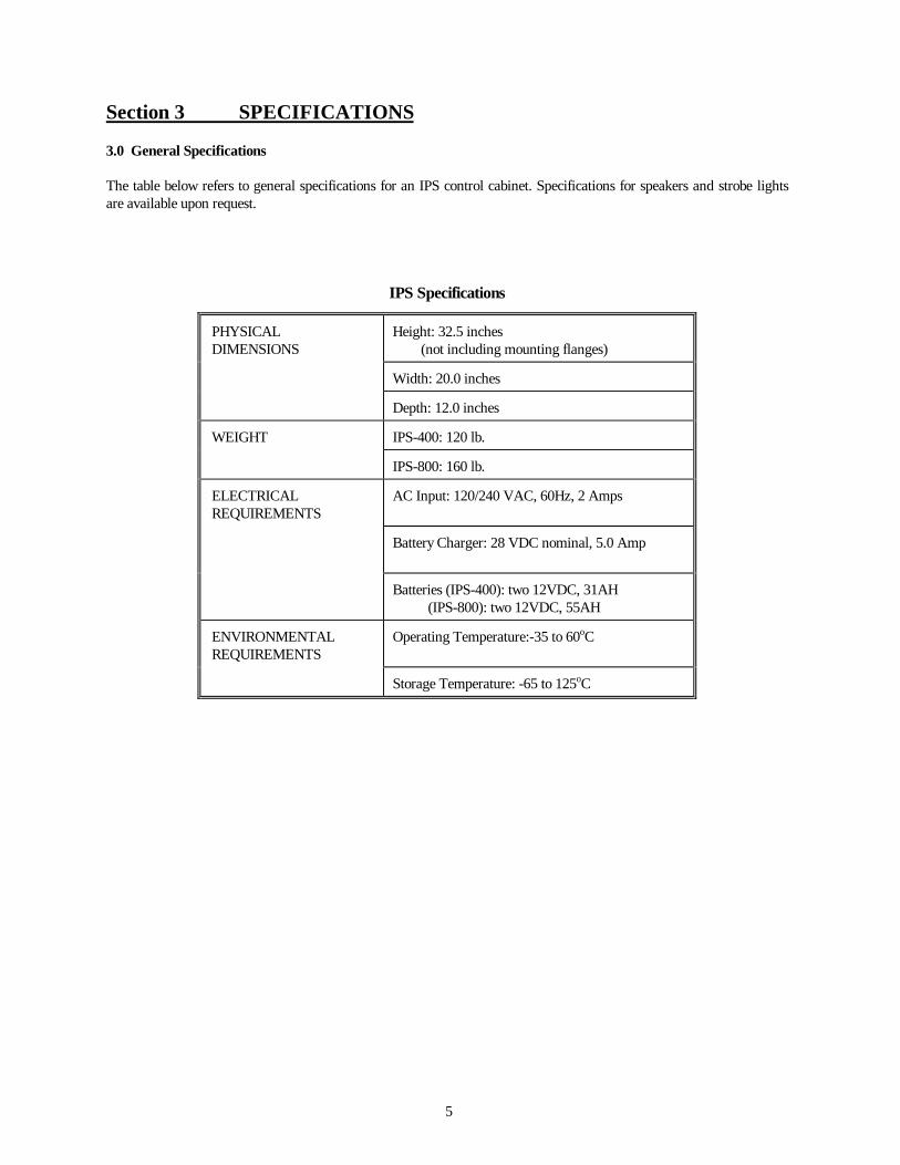
The table below refers to general specifications for an IPS control cabinet. Specifications for speakers and strobe lightsare available upon request.
IPS Specifications
PHYSICAL DIMENSIONS
Height: 32.5 inches (not including mounting flanges)
Width: 20.0 inches
Depth: 12.0 inches
WEIGHT IPS-400: 120 lb.
IPS-800: 160 lb.
ELECTRICAL REQUIREMENTS
AC Input: 120/240 VAC, 60Hz, 2 Amps
Battery Charger: 28 VDC nominal, 5.0 Amp
Batteries (IPS-400): two 12VDC, 31AH (IPS-800): two 12VDC, 55AH
ENVIRONMENTAL REQUIREMENTS
Operating Temperature:-35 to 60oC
Storage Temperature: -65 to 125oC
6
Section 4 MODULE DESCRIPTION
4.0 IPS Module Descriptions
This section provides an overview of the individual electronic modules in an IPS.
• ESC-864 (Controller)• Power Amplifier(s)• System Driver Board• Battery Charger• Batteries
4.1 ESC-864 (Controller)
The ESC-864 Controller is the microprocessor-based core of the IPS. The ESC-864 houses the following:
local pushbuttons and LED indicators, the ESC-864 controller circuit board, the tone generator,
as options: digital voice, landline or RF link interfaces, radio receiver/transceiver.
4.1.1 Local Controls and LED Indicators
Local control is available at the front panel of the ESC-864, as described below.
Local Control and Indicator Functions
Control orIndicator Control or Indicator Function
CLR Stops warning tones prior to completion of programmed time. Some tones "ramp down"prior to turning off.
WAIL Siren tone. Initiates a slow rise, high-pitched tone for four seconds, followed by a softer,winding-down for one second. This sound pattern continues for as long as the timingduration is set.
ATK Siren tone for National Attack. Initiates a faster rise, high-pitched tone for one second,followed by a winding down tone for one second. This sound pattern continues for as longas the timing duration is set.
ALRT Siren tone for Alert. Initiates a quick rise then steady tone for as long as the timingduration is set.
AIR HORN Siren tone. Initiates a pulsing buzzing tone which blasts in intervals of 1.6 seconds for aslong as the timing duration is set.
HI-LO Siren tone. Initiates a highly pitched tone with a "Dee" sound for 0.8 seconds, followed bya lower-pitched "Doo" sound for 0.8 seconds. This sound pattern continues for as long asthe timing duration is set.
WHP Siren tone for Whoop. Initiates a high-pitched, repetitive rise-only sound for three seconds,then stops. This sound pattern continues for as long as the timing duration is set.
7
Control orIndicator Control or Indicator Function
WAIL 5 SEC Siren tone. Initiates a high pitched tone, followed by a softer, winding cry. Actual on timeis more than 5 seconds. NOTE: The five-second WAIL siren tone is often referred to as theNOON TEST.
CW CW is not used with an IPS.
CCW CCW is not used with an IPS.
SI TEST® Initiates the SI TEST tone and the diagnostic SI TEST routine.
XMIT TONE For use with remote station radio transceiver; causes transmission of DTMF tone via RFlink for tone modulation adjustment. The transmit tone level is adjusted by the transmitlevel potentiometer on the ESC 864 front panel.
XMIT Actuates remote station radio transmitter push-to-talk (PTT) circuit. When tone squelch isused with the transmitter, the XMIT function is used to adjust tone squelch modulation.
DC DC LED indicates that DC voltage is present during a siren tone or a SI TESTactivation.
FULL Full LED indicates that all properly loaded remote station speakers are operating during asiren tone or a SI TEST activation. Speakers < 60 Watts may not indicate correctly.
DIAGNOSTICOUTPUT
Diagnostic output (25 pin connector) serves as the ESC 864 PC board (controller)input/output port for diagnostic and programming purposes. System diagnostic informationand programming is accomplished with the Whelen MDK-864 Diagnostic Keyboard usedin servicing or testing the IPS.
REPROGRAM This REPROGRAM pushbutton, which is recessed, is for use by technicians trained in theuse of the MDK-864 diagnostic keyboard for factory service purposes only. CAUTION:Pressing this button will erase customer-specific programming and return the ESC864 controller to default settings. Pressing this button will render the siren stationunresponsive to customer-specific activation until the unit is reprogrammed.
ROT ROT (LED) is not used with an IPS.
PART PART (partial) LED indicates that at least one speaker driver operated during a warningtone or a SI TEST activation. Speakers < 60 Watts may not indicate correctly.
AC AC LED indicates that AC voltage was present during a warning tone or a SI TESTactivation.
CLIPPINGINDICATOR
The clipping indicator LEDs illuminate when a warning tone is active or when a publicaddress signal of sufficient amplitude is processed by the tone generator.
MIC VOLUME This knob controls the output volume of local public address announcements. Indetermining a sufficient volume adjustment for local public address announcements, theclipping indicator LEDs should just begin to blink when the local announcement isproduced. This "blinking" indicates the maximum amplification of sound with negligibledistortion.
MIC This microphone jack is used for local public address announcements. Upon insertion of amicrophone plug into the jack, the timer set LED may come on for approximately onesecond. To use the microphone, squeeze the lever on its side completely and verify that thetimer set LED illuminates. Use of the local microphone disconnects remote radio audio
8
Control orIndicator Control or Indicator Function
input from the tone generator's input, eliminating outside interference. Removing themicrophone from the microphone jack restores the remote radio audio input.
XMIT The XMIT LED, when illuminated, indicates that the ESC-864 is actuating the IPStransmitter push-to-talk (PTT) circuit and is transmitting data or a test tone.
PWR The PWR (power up) LED indicates that all modules in the remote station are powered upand all parts of the system are ready to operate. For systems using AC power operating theIPS battery charger, this LED is on at all times unless an AC outage occurs, prompting theIPS to go into a power-saving mode.
DEC The DEC (decoder active) LED illuminates when the DTMF tone decoder receives andprocesses incoming DTMF tones. The DEC LED appears to flash when it illuminates. Thisis a normal condition, as it blinks for every valid DTMF digit that is decoded.
PROG The PROG (program) LED only illuminates when the MDK-864 Diagnostic Keyboard isused and the program switch on the MDK-864 is in the ON position. When the programLED is illuminated, the siren cannot be activated remotely.
SQ The SQ (Squelch) LED illuminates when the radio receiver detects that the appropriatecarrier frequency is active. For systems that have the optional programmable receive tonesquelch tone decoder, the LED only illuminates when the receive frequency, as well as thesubaudible tone squelch frequency tone, is detected.
TIM The TIM (timer set) LED illuminates whenever the system is activated by either radio link,landline control, or from the front panel for any of the siren functions or public address.
XMIT LEVEL The XMIT (transmit) LEVEL adjustment potentiometer controls the modulation of theDTMF tones that are transmitted when the remote station status reporting option is used.
RADIOLEVEL
The RADIO LEVEL adjustment potentiometer is used to set the audio level that will bepassed on to the tone generator from a radio receiver or landline audio input.NOTE: The transmit level and the radio level adjustment potentiometers are preset atthe factory and should not be changed except by qualified personnel.
POWER AMPLEDs
The power amplifier LEDs, located on the front panel to the left of the ESC-864 case faceplate, are used for visual inspection and verification regarding the wiring circuit betweeneach power amplifier channel and its respective speaker drivers. One speaker driver iswired to each power amplifier channel by a dedicated pair of wires. Upon activation of awarning or siren tone, a SI TEST tone, or a public address signal of sufficient level, theseLEDs should illuminate, indicating a complete circuit. NOTE: The LEDs assume the IPSis operating under proper speaker loading capacity. Without sufficient loading, theLEDs will not operate effectively. Speakers < 60 Watts may not indicate correctly.
9
4.1.2 ESC-864 Controller Circuit Board
The ESC-864 Controller board allows for local activation of warning signals, plus remote control interfacing. It alsomonitors system status and provides visual status indicators as described in the previous tables. The ESC-864 PC boardcontrols the tone generator. All DTMF processing is performed on the ESC-864 board.
4.1.3 Tone Generator
The tone generator is a separate PC board that is mounted to the ESC-864 board. The tone generator receives itscommands from the ESC-864 board. All siren tones and public address audio processing are accomplished within thetone generator. The microphone jack and microphone volume control, as well as a clipping indicator, are also part of thetone generator functionality.
4.1.4 Digital Voice (option)
The optional digital voice module is mounted onto the tone generator in the ESC-864 case. The digital voice moduleallows the IPS to store prerecorded, digitized messages for transmission over the public address portion of the system.Prerecorded, digitized 15, 30 and 60-second messages are available.
4.1.5 Landline or RF Link Interfaces (options)
As an option. the IPS may be remotely controlled either landline or RF link. Either method communicates via a DTMFprotocol. Remote control may be one-way or two-way. The one-way option simply controls the IPS, while the two-wayoption controls the IPS and reports IPS status back to a central control point.
The built-in DTMF capability responds to activation commands and generates status responses. The formats anddefinitions for Activation Commands and Status Responses are described below.
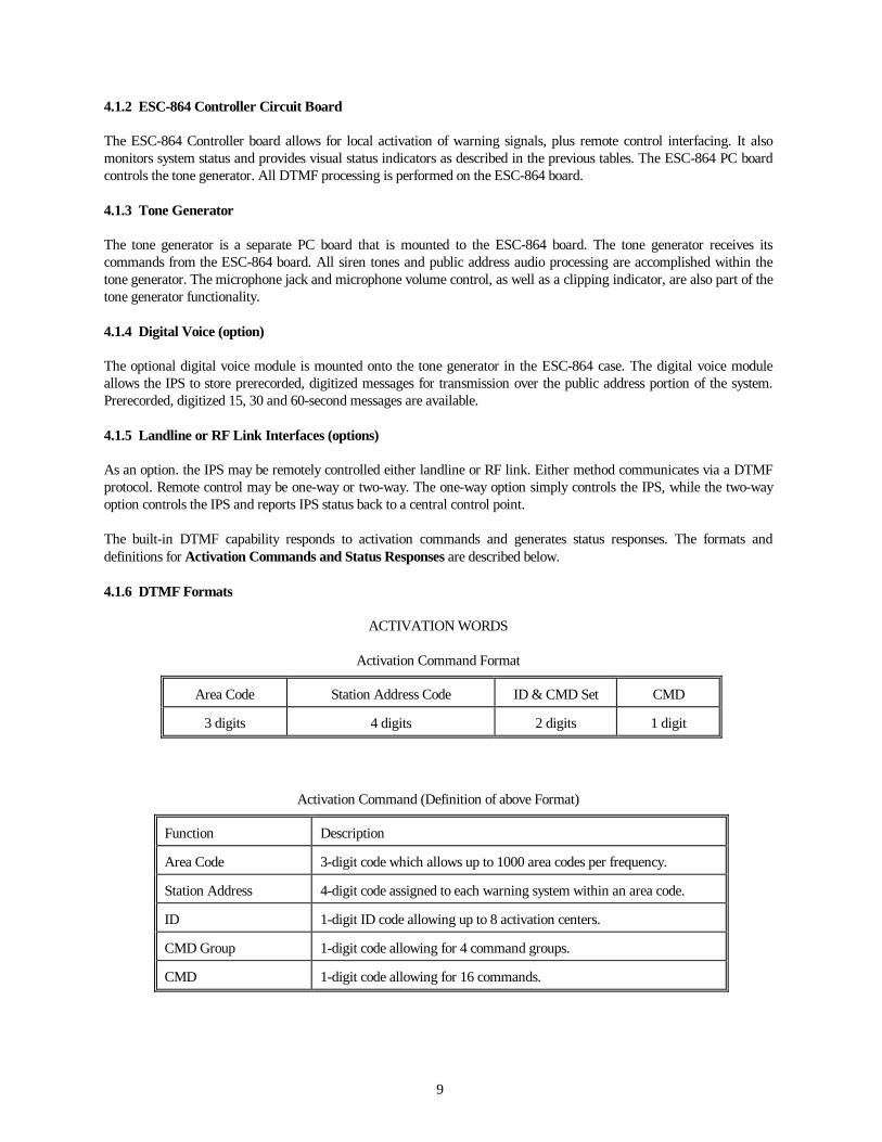
4.1.6 DTMF Formats
ACTIVATION WORDS
Activation Command Format
Area Code Station Address Code ID & CMD Set CMD
3 digits 4 digits 2 digits 1 digit
Activation Command (Definition of above Format)
Function Description
Area Code 3-digit code which allows up to 1000 area codes per frequency.
Station Address 4-digit code assigned to each warning system within an area code.
ID 1-digit ID code allowing up to 8 activation centers.
CMD Group 1-digit code allowing for 4 command groups.
CMD 1-digit code allowing for 16 commands.
10
Status Response Format
Area Code Address Code Length Response Status Bytes
Digital Analog
3 digits 4 digits 1 digit 2 digits variablelength
variablelength
Status Response (Definition of Format)
Function Description
Area Code 3-digit code which allows up to 1000 area codes perfrequency.
Station Address 4-digit code assigned to each warning system within anarea code.
ID 1-digit ID code identifies the type of siren.
Length Informs base station as to the length of the response word.
Response 2-digit code which reports status of alarm responses,inquiries, and command groups.
StatusBytes
2 to 8-digit code carrying digital/analog statusinformation.
IPS Status Descriptions
Status Reporting Information (Subject) Status Designation
Station AC Power on/off
Station AC Line Voltage 3-digit representation
Station DC Voltage 2-digit representation
Partial Amplifier and Speaker Driver operation
Ambient Temperature 3-digit representation
System Power Up Status on/off
Intrusion Alarm instant status response for open door condition
Low Battery Condition low battery status has been reached
Receiver Signal-to-Noise Ratio (S/N) 2-digit activation count
11
The ESC-864 board reports status information to a central control point in response to the following alarm conditions:
- a change-of-state alarm (user selectable on/off)
- instant response to individual activation (user selectable on/off) or
- response to individual interrogation.
In the event of an alarm condition, the ESC-864 board will transmit its status report three times to ensure that themessage is received. The first transmission will happen immediately upon change of status, the second transmissionfifteen (15) seconds after the first, and the third fifteen (l5) seconds after the second transmission. If, after thesetransmissions, the RF link remains busy, the ESC-864 PC board will terminate transmission. With respect to this latterstatement, a squelch detect circuit is included within the ESC-864 board's design. This feature prevents interference withother transmissions on the RF link. The squelch detect circuit will not transmit status information if the RF channel isbusy, and it will wait for a clear channel prior to transmitting. The ESC-864 may be configured to operate in the squelchdetect mode on the basis of noise squelch or tone-coded squelch.
The ESC-864 board provides service and diagnostic information concerning its radio receive link upon initiation of adiagnostic sequence from the central control point by an E-864/M Encoder and Status Display. In response to carrier-only and tone sequence, the ESC-864 PC board examines its receive signal-to-noise ratio and transmits this informationback to the central control point.
4.1.7 Radio Receiver/Transceiver (option)
The radio receiver/transceiver is typically installed in the ESC-864 housing. The radio receiver/transmitter option isavailable at low band VHF (30-50 MHz), high band VHF (150-170 MHz), or UHF (450-470 MHz).
4.1.8 Local Microphone Input and Volume Control
The local microphone controls are mounted on the front panel of the ESC-864 housing, to allow the user to plug in amicrophone to access the public address channel of the IPS. While it may be obvious that the microphone plugs into thejack, and that the microphone volume control knob allows for adjustment of the output level, a clipping indicator abovethe microphone volume control knob is provided to indicate the distortion level of the microphone. During PA, theclipping indicator should be flickering on and off (i.e., operating at minimal illumination levels).
4.1.9 System Diagnostics
All IPS systems are equipped with diagnostic capabilities. The diagnostics provide a basic summary of the systemoperations concerning AC power, DC power, speakers, and power amplifiers. As previously described, the informationfrom the diagnostics is presented by the various LEDs on the front panel of the ESC-864 housing.
4.2 Power Amplifier Operation
The power amplifiers are located on the backside of the front panel of the IPS. As previously stated, one 400 W poweramplifier is used in an IPS-400, while an IPS-800 is equipped with two power amplifiers. Each power amplifier has four(4), 100 W speaker channels, for a total of 400 watts per amplifier.
Each power amplifier is powered by 24 VDC. The amplifiers are hard-wired to the system driver board. Each poweramplifier is protected by a 30 Amp fuse, near its connectors. The failure of one amplifier does not cause the failure asecond amplifier; however, all four power amplifier channels within a faulty power amplifier will fail in the case of ablown fuse.
Each power amplifier is mounted on the backside of the front panel so that four (4) red LEDs are visible (on the frontside of the front panel), one for each 100 W channel of each power amplifier. These LEDs are used to monitor the
12
electrical circuit between a power amplifier channel and its respective speakers. The LEDs, indicate a complete circuitfrom the respective power amplifier channel to the speakers and back when the power amplifier is in operation. Anactive LED indicates that the power amplifier channel, system driver board, speaker wires, and speaker(s) arefunctioning when a warning signal tone or public address mode is active. Speakers < 60 Watts may not indicatecorrectly.
In the public address mode of operation, each appropriate power amplifier channel(s) increases its amplification outputby an additional 25% to compensate for the differential in power between voice audio signals and siren warning signals.This increase in amplification assists in providing voice broadcasting at warning signal tone ranges.
4.2.1 Speaker Configurations
The IPS power amplifier(s) can be connected to various speakers and speaker configurations or arrangements. The tablebelow shows some common speakers and the number of speakers allowed per each 100 W channel on each poweramplifier.
Common Speakers and Speaker Arrangements
SPEAKER DESCRIPTION MAXIMUM SPEAKERSPER CHANNEL
The WS15T/WS30T are weatherproof, 15 to 30 watt re-entrant loud speakerswith multi-tapped transformers for output adjustments. The WS15/WS30 do nothave transformers.
6: WS15T or WS153: WS30T or WS30
The WS15TR/WS15TEN are 15 watt re-entrant loudspeakers with multi-tappedtransformers for output adjustment. The WS15TR speaker is ideal for recessedmounting applications. The WS15TEN speaker is for recessed mounting inceiling tiles.
5: WS15TR5: WS15TEN
The WS100 heavy duty, 100 W re-entrant loud speaker with a wide-angle horn. 1: WS100
The WS100TCH Heavy Duty weatherproof, 100 watt wide-angle re-entrantspeaker with multi-tapped transformer output adjustment. The WS100CH doesnot have the transformer.
1: WS100TCH or
1: WS100CH
The WSXPL60T loud speaker is used in areas having explosive or combustibleatmospheres. The speaker is UL and CSA listed, 60 W re-entrant, wide-angleloud speaker and has a multi-tapped transformer.
1:WSXPL60T
Individual product descriptions may be requested from the sales office, for each speaker in the table.
13
4.3 System Driver Board
The system driver board, shown to theright, provides a number of functions inthe IPS. The functions are described inparagraphs 4.4.1 through 4.4.5.
4.3.1 Audio Signal Distribution
Terminal block 1 (TB1) provides eightsets of terminals, labeled with a plus (+)and a minus (-), as shown.
Terminal block 2 (TB2) is not used inan IPS system.
4.3.2 IPS Silent Test Operation
The IPS can produce an inaudible tonefor system testing purposes. Thefunction of this feature, which may beinitiated by pressing the SI TEST®pushbutton on the front panel of theESC 864 controller, is to exercise thesystem speaker drivers in the samemanner as a fully powered, audiblewarning signal.
By pressing the SI TEST® pushbutton,the user may observe the poweramplifier LEDs to determine if acomplete circuit is active between eachspeaker (or group of speakers) and therespective power amplifier channel. Thesilent test may also be initiated by aremote command.
The results of a silent test are presentedon the LED displays, on the front panel,as shown in the table. Speakers lessthan 60 Watts may not indicatecorrectly.
J6
J3
J4
J5
J1
F1
J2
SW1
TB2
TB1
TB3
3 AMP
PC. BD #67729
.325 CENTERS
.250 CENTERS
SPEAKER AUDIO 1+
SPEAKER AUDIO 1-
SPEAKER AUDIO 2-
SPEAKER AUDIO 2+
SPEAKER AUDIO 4+
SPEAKER AUDIO 4-
SPEAKER AUDIO 3-
SPEAKER AUDIO 3+
SPEAKER AUDIO 7+
SPEAKER AUDIO 7-
SPEAKER AUDIO 8-
SPEAKER AUDIO 8+
SPEAKER AUDIO 6+
SPEAKER AUDIO 6-
SPEAKER AUDIO 5-
SPEAKER AUDIO 5+
SHIELD GROUNDS
14
Silent Test LED Indicators
LED STATUS INFORMATION COLOR
AC On AC site power Red
DC On DC power > 19 VDC Red
PART On Partial Speaker Driver/Amplifier Operation Red
FULL On Full Speaker Driver/Amplifier Red
The diagnostic routine of the IPS is processed for each inaudible or full power activation of the system, and thediagnostic LED indicators represent the results of the most current activation.
The complete results of the inaudible test are collected and encoded by the ESC-864 PC board for transmission back tothe central control point. In addition to the status information mentioned in the table, the ESC-864 also reports thefollowing information via its RF or landline communication link.
•DC Voltage (system battery voltage)•AC Voltage•Ambient Temperature, a 2-digit representation•Receiver Link S/N , a 2-digit representation•Activation Count
If all of the SI TEST® LED indicators are illuminated following a test, then all diagnostic routines have beensuccessfully completed, verifying proper station operation. The LED display of the IPS may be programmed to remain onuntil cleared, or to extinguish after a predetermined time period.
4.3.3 Power Saving Logic
The system driver board also features a power saving device. In the event of a loss of incoming power from an ACsource, the system will power itself down after thirty (30) seconds to conserve the batteries by using less energy forstandby operation. When AC is restored, the IPS automatically reverts to full power-up mode and the battery charger re-charges the batteries.
4.3.4 DC Voltage Regulator
The system driver board produces 12 volts DC, from the 24 VDC supply, to power the ESC-864 PC board and theoptional radio. A 3 amp fuse is in line with the 12 volt DC supply.
4.4 Battery Charger Operation
The battery charger has the primary function of maintaining the system battery supply to full capacity. The batterycharger provides 5 Amps of charging current to the batteries. The operational status of the battery charger can be viewedby the DC LED during warning signal tone, activation of the SI TEST®, or when the system is powered up. In addition,a green LED on the charger, indicates proper charging. To maintain optimum battery capacity, the IPS should beexercised on a frequent basis using SI TEST® and full-power activations.
4.5 Batteries
The batteries are located in the lower compartment of the IPS. Two 12 VDC, 31 AH Gel type batteries are required tooperate an IPS-400, while two 12 VDC 55 AH batteries are required to operate an IPS-800. Detailed installationinformation for the batteries is provided in Section 5.
15
Section 5 INSTALLATION
5.0 Installation Instructions
The installation instructions are presented as follows:
Site SelectionReceiving/Unpacking the IPSInstallation of the IPS CabinetConduit Openings for the IPS CabinetAC WiringSpeaker Wiring
These steps are discussed in detail in this section. Once the installation steps are complete, the IPS is ready for anoperational checkout.
5.1 Site Selection
Selecting the site for an IPS requires careful planning to achieve optimal use, range, and effect of the system. Considermaintenance and future expansion when selecting a cabinet mounting location.
Typically, a two conductor, 18 AWG cable is run.
The cabinet has mounting tabs or flanges on 14 inch centers, for wall mounting. For outdoor applications, drain holesneed to be drilled into the upper compartment of the IPS. Consult Whelen Engineering Company, Inc. for advice onoutdoor applications.
NOTE
As part of the site selection planning process, the local utility company should be consulted with respect toinstallation of AC service. The location of the IPS site should be checked for the quality of the AC serviceand to ensure there will be no electromagnetic interference at the site. Also, AC power sources subject toexcessive power surges or transients are not acceptable. A site should also be appraised for antennaplacement and for radio reception for systems equipped with RF link interfaces.
16
R
IPSSYSTEM
100 WATT SPEAKER
60 WATTSPEAKER
3 - 30 WATTSPEAKERS
4 - 15 WATTSPEAKERS
= SPEAKER AUDIO (2 CONDUCTORS)
CAUTION
In planning for speaker arrangement and placement, the use of hearing-protective devices should beconsidered for people working in close proximity to heavy-duty speakers connected to the IPS.
17
5.2 Receiving/Unpacking the IPS
An IPS is typically shipped with the following items packed on a single shipping pallet: (a) two, 12 volt, Gel typebatteries (31 AH for an IPS-400 or 55 AH for an IPS-800; and (b) the IPS cabinet with the appropriate electronics, asordered. If a radio receiver/transceiver was ordered as part of the system, an antenna may be included on the pallet. Formultiple-system purchases, pallets may be shipped carrying multiple IPS cabinets, for example, while other pallets maycontain antennas and batteries. Speakers are commonly packaged together and sent simultaneously with the system.Before shipment, each IPS has been pre-assembled, wired, and tested at the factory. Each IPS is shipped in an uprightfashion. The receiver of any shipment(s) should check each shipment against the purchase order to ensure that acomplete system (as ordered) has been shipped.
5.3 Installation of the IPS Cabinet
The IPS cabinet is typically mounted to an inside wall of a building. The cabinet is equipped with two mountingflanges on the top and two mounting flanges on the bottom, as shown in the drawing. The top flanges have two7/16” holes and the bottom flanges have two 7/16” slots, in order to accommodate 3/8” hardware. The holes areon 14” centers.
The IPS-400 and the IPS-800 are the same size, however, the IPS-400 weighs approximately 120 pounds and theIPS-800 weighs approximately 160 pounds.
Be sure to allow enough room to fully open the cabinet doors. Also, make sure there is room for conduit andwiring, typically on the left side of the cabinet.
Mounting Details
14.0(TYP. BOTH ENDS)
33.2532.5
20.0
12.3 3.0
34.5
MOUNTING FLANGESWITH 7/16" OPEN SLOTS
MOUNTING FLANGESWITH 7/16" HOLES
18
5.3a Installation of the “Type C” Cabinet
For “Type C” cabinet installation only
The IPS cabinet is typically mounted to an inside wall of a building. The cabinet is equipped with two mountingflanges on the top and two mounting flanges on the bottom, as shown in the drawing. The top flanges have two7/16” holes and the bottom flanges have two 7/16” slots, in order to accommodate 3/8” hardware. The holes areon 14” centers.
The IPS-400 and the IPS-800 are the same size, however, with a “Type C” cabinet the IPS-400 weighsapproximately 150 pounds and the IPS-800 weighs approximately 190 pounds.
Be sure to allow enough room to fully open the cabinet doors. Also, make sure there is room for conduit andwiring, typically on the left side of the cabinet.
Mounting Details
14.0(TYP. BOTH ENDS)
50.6
49.8
20.0
12.3 3.0
51.8
MOUNTING FLANGESWITH 7/16" OPEN SLOTS
MOUNTING FLANGESWITH 7/16" HOLES
19
5.4 Conduit Openings for the IPS Cabinet
The installer must punch entry holes in the IPS cabinet. The holes are typically made on the left side of thecabinet, as shown in the drawing.
Note: The location of the holes, the size of the holes and the number of holes is left to the installers discretion. However, the drawing shows the factory’s recommendation. Following the factory recommended hole pattern will ensure compatibility with future options or system expansion. Do nottry to line up the AC conduit with the AC outlet box in the cabinet.
Refer to the drawing below. Notice the 5” x 7” cross-hatched open area , 3” from the back wall and 5” from thebottom shelf. Locate two holes in the 5” x 7” open area. Working from the inside of the cabinet, drill a pilot holefor each of the holes. Open the top hole to 1 1/4” diameter and the bottom hole to 3/4” diameter.
The 1 1/4” hole is for the speaker conduit. The 3/4” hole is for the AC service and the antenna cable, if anoptional radio is installed. Run the speaker conduit to the 1 1/4” hole and the AC conduit to the 3/4” hole. Theuse of “L” or “T” fittings is advised to simplify routing of speaker wires and the optional antenna cable.
Note: If the cabinet is in an area where it is exposed to water, the conduit fittings to the cabinet must be properly sealed.
Conduit Hole Location
3"
5"
20
5.5 AC Wiring
Make sure the battery charger is unplugged from the AC outlet in the left rear corner of the control cabinet. Routethe AC service wire through the cable clamp on top of the box. Make the AC connections to the outlet, accordingto local electrical codes.
Locate the green wire in the outlet box. This is the cabinet chassis ground. Connect the green wire to the groundwire of the electrical service, within the outlet box. Make a ground connection from one of the lower mountingtabs to earth ground using minimum of 4 AWG copper wire. Always follow local codes.
Leave the battery charger unplugged.
AC Outlet Wiring
NOTE
The electrical service is subject to local codes and conditions. The IPS requires AC power only for the purpose ofoperating the battery charger.
21
5.6 Speaker Wiring
All of the speakers audioconnections are made through theSystem Driver Board, located on theleft side of the back wall of the IPScabinet.
The upper most terminal block isTB1. It is the connection point forthe audio signals to the speakers (fordirect connect speakers) or to thespeakervisors (for supervisedspeakers). Refer to the drawing.Starting at the top, notice that theterminals are in pairs, 1 through 8.Also notice that each pair has a (+)terminal and a (-) terminal. Eachterminal pair can drive up to 100watts, therefore, speaker loadsgreater than 100 watts must bedistributed through more than oneterminal pair.
TB2 is not used.
TB3 is not used.
Remember to keep track of the audiocables and cable polarity. The audiocable must be connected to theproper polarity at each speaker.
J6
J3
J4
J5
J1
F1
J2
SW1
TB2
TB1
TB3
3 AMP
PC. BD #67729
.325 CENTERS
.250 CENTERS
SPEAKER AUDIO 1+
SPEAKER AUDIO 1-
SPEAKER AUDIO 2-
SPEAKER AUDIO 2+
SPEAKER AUDIO 4+
SPEAKER AUDIO 4-
SPEAKER AUDIO 3-
SPEAKER AUDIO 3+
SPEAKER AUDIO 7+
SPEAKER AUDIO 7-
SPEAKER AUDIO 8-
SPEAKER AUDIO 8+
SPEAKER AUDIO 6+
SPEAKER AUDIO 6-
SPEAKER AUDIO 5-
SPEAKER AUDIO 5+
22
5.7 Radio Option
Locate the antenna so that it is clear of any obstructions. Ground the antenna bracket using a minimum of 4 AWGcopper wire to a suitable earth ground.
If the unit is equipped with a transmitter, a coax protector has been provided. The protector is shipped in thebattery compartment. Locate the protector as close as possible to where the antenna cable enters the cabinet. Themounting hardware is included with the protector.
Loosely coil and secure any excessive antenna cable inside the cabinet. Be careful not to crimp the cable or createany sharp bends. After the protector is installed and all of the radio connections made, the antenna may betrimmed.
23
Section 6 BATTERIES
6.0 Battery Installation
As previously mentioned, an IPS-400 comes with two 31 Amp-hour batteries. These fit as shown in the drawing.The IPS-800 comes with two 55 Amp-hour batteries. These are larger than the 31 Amp-hour batteries. They mustbe rotated 90 degrees to be installed.
6.1 Battery Connections
Unplug the battery charger from the AC outlet. Connect the red cable to the (+) terminal of the left battery.Connect the black cable and the gray thermistor cable to the (-) terminal of the right battery. Last connect theinterconnect cable to the (-) terminal of the left battery and then the (+) terminal of the right battery.
Note: A spark may occur when the last terminal connection is made.
Battery Compartment Connections
CAUTION: Do not allow battery terminals, cables terminals or uninsulated tools to make contact with the aluminum cabinet.
1/4"-20 X 3/4"HEX HEAD BOLT
PPOSITIVE
CABLEINTERCONNECT
1/4" LOCKWASHER
1/4-20 HEX NUT
THERMISTOR ASS'Y
(RED)
NEGATIVE(BLACK)
24
Section 7 CONTROLLER PROGRAMMING
7.0 ESC 864 Controller Programming
This section covers user programmable features of the ESC-864 controller, in the IPS. A number of parameters arefactory set in Electronically Erasable Programmable Read Only Memory (E2PROM) others are controlled by DipSwitch settings.
7.1 User E2PROM Programming
Certain parameters of the IPS may be user programmed to adapt the system to specific needs. User programming isaccomplished by inputting information to the ESC 864 controller board using a Whelen MDK-864. (The "MDK" inthe Whelen MDK-864 stands for Microprocessor Diagnostic Keyboard.) Factory settings for each IPS are includedon the Test Sheet, shipped in the upper compartment of the IPS. Refer to the manual on the MDK-864 forparameter changes. Use of the Whelen MDK-864 is discussed in the manual, MDK-864 MicroprocessorDiagnostic Keyboard.
Since the programming variations are too numerous to address in this manual, the remainder of this section isintended to acquaint an IPS user with the basic options available for user-definable programming.
7.2 ESC 864 Encoding/Decoding Parameters
The IPS is equipped for remote activation and status reporting. The IPS requires programming to recognizecommands from, and to report status to, a central control point. The IPS may also be programmed to operate in amultiple-system network, where each IPS cabinet has a specific identification code. The IPS Test Sheet, thataccompanies each IPS indicates the following access and identification information:
This information is programmed into the ESC-864 controller E2PROM at the manufacturer's facilities.
7.3 Warning Tone Timer Programming
The ESC-864 board determines run time duration for each siren tone and for the PA announcement. The typicalfactory setting is three minutes. The Test Sheet, that accompanies each IPS, indicates timer settings.
NOTE
The Test Sheet identifies tones only as Tone 1, Tone 2, etc. For purposes of clarity, these tones are identifiedbelow as column two.
25
Warning Tone Signal/PA Announcement Timing Information
TONE SIGNAL DURATION*
1 WAIL __ -- __ __
2 ATTACK __ -- __ __
3 ALERT __ -- __ __
4 PA __ -- __ __
5 AIR HORN __ -- __ __
6 HI/LO __ -- __ __
7 WHOOP __ -- __ __
8 NOON TEST** __ -- __ __
*Duration is indicated as: Minutes (_) and Seconds (_ _). Unless specified otherwise by a customer, the standard factory programming is for an event duration of three minutes (3-00), with the exception of the five-second test.**NOON TEST is referred to as a 5 SEC WAIL on the front panel of the ESC-864.
7.4 DIP Switch Programming
The ESC-864 controller board has two, eight-position dip switches. The switches are set by the manufacturer inaccordance with the users application and the software/hardware options that are installed into the system at thetime of manufacture. The dip switches control function settings and instant status settings. The Test Sheet, includedwith each IPS, refers to these settings as Function Dips (SW 1) and Status Dips (SW 2).
Function Dips (SW 1) Programming Functions
Position Function Setting/Use
1 Not Used Off
2 Decoder Format On (10 digit)Off (8 digit)
3 SI TEST LED On (30 sec clear)/Off (latch)
4 Warning Signal (Siren) Type On (oscillating)Off (stationary)
5 AC Battery Check On/Off
6 Instant Response On/Off
7 Immediate Response On/Off
8 Master XMT On/Off
26
Instant Status Dips (SW 2) Programming Functions
Position Function Setting/Use
1 AC On/Off
2 Intrusion On/Off
3 Input Not Used
4 Input Not Used
5 Input Not Used
6 Full On/Off
7 Partial On/Off
8 Tone Gen Bias On/Off
27
Section 8 TESTING & TROUBLESHOOTING
8.0 System Testing and Troubleshooting
Throughout this section, testing and troubleshooting pertain to operational checkout procedures and fault-isolationprocedures. Successful completion of the operational checkout verifies proper operation of the IPS. Tables 8-1 through 8-2 correlate faults to isolation procedures and associated corrective action. Troubleshooting procedures are presentedunder the assumption that there is but one malfunction at a time. After all repairs are made, an operational checkout ofthat malfunctioning module should be repeated to make sure that any module replacement did not introduce a newmalfunction.
The silent test feature is the key to system checkout and testing. If the SI TEST® does not isolate the problem, follow theprocedures below to assist in further fault isolation testing and troubleshooting. If the procedures in these subsections donot isolate the fault, a more detailed diagnostic/testing tool, the MDK-864, or Microprocessor Diagnostic Keyboard, isused by a trained technician to isolate the problem.
8.1 Initial Operational Checkout
PROCEDURE NUMBERAND TOPIC
PROCEDURAL ACTIVITIES
1: Batteries Check the series connection between the batteries in the IPS lower compartment.
2: AC Service Make sure there is a proper connection between the AC service and the AC workbox.
3: Power Check If there is a dedicated AC disconnect switch, ensure that the switch is in the ON position.
4: Functional Observation Activate a local SI TEST® to verify that the IPS is operating properly.
8.2 System-Level Faults and Troubleshooting Procedures
The system-level faults, isolation procedures and corrective actions are intended to assist in isolating the cause andlocation of a failure within the IPS control cabinet, as well as any associated warning devices.
NOTE
In troubleshooting on the IPS, the user is reminded that certain procedures and tests may cause the IPS to produce anaudible signal. The user should exercise discretion regarding the production of warning signals. Most of thetroubleshooting procedures may be performed without producing an audible signal.
28
System-Level Faults and Troubleshooting Procedures
FAULT ISOLATION PROCEDURE CORRECTIVE ACTION
IPS will not activatevia local controls.
Determine whether batteryvoltage is less than 19 VDC.
Perform battery system faults and troubleshooting procedures. Ifbatteries do not attain and maintain 19 VDC, replace batteries.
Battery voltage isless than 19 VDC.
Verify 120 VAC present.
Check the fuse on the batterycharger.
Supply 120 VAC service.
Replace the fuse.
IPS will not activatevia local controls.PWR LED is on.
Observe all wiring andconnections.
Repair or replace broken cabling/wiring between modules. If wiringor circuitry within a module appears damaged, contactmanufacturer’s service personnel.
IPS will producetones audible nearcabinet but fail toproduce tones atdesignated soundlevels.
Check the tone generatorconnector to the system driverboard, including the cableleading to the ESC-864 case.
Check the power amplifiercables and connections.
Inspect power amplifier fuses.
Observe speaker driver (i.e.,wire) connections to terminalstrip on the system driver board.
Refit the tone generator connector. Check cable/wiring pathbetween tone generator connector and connection to ESC-864. Ifdamaged, have repaired or replaced.
Check cable/wiring path between power amplifier connections onthe power amplifier(s) and the associated connections on the systemdriver board. If loosened on the power amplifier(s), make properconnection. If loosened or damaged on the system driver board,have manufacturer’s personnel repair or replace.
Replace fuse(s), as required.
Make proper connections. If damaged, have wires repaired orreplaced. If problem not resolved, refer to manual on speakers. Ifspeakers check out properly, contact manufacturer servicepersonnel.
All power amplifierLEDs do notilluminate duringsignal activation.
Observe power amplifier fuse.
Observe power amplifier cablesand connections from eachpower amplifier to the systemdriver board.
Observe connections of speakerdrivers (wires) on terminal stripof system driver board.
Replace fuses.
Make proper connections. If connections, cables/wires are damaged,have repaired or replaced.
Make proper connections. If connections, cables/wires are damaged,have repaired or replaced.
One-to-three poweramplifier channelsdo not illuminateduring signalactivation.
Observe connections of speakerdrivers (wires) on terminal stripof system driver board.
If connections are proper and not damaged, connect a pair ofspeaker wires from an adjacent, working power amplifier channelon the terminal strip into the apparently faulty power amplifierchannel on the terminal strip.
Press the SI TEST® pushbutton. If the power amplifier channelLED illuminates, the power amplifier channel is functioningproperly. The speaker driver (wires) that was originally connected tothe power amplifier channel is apparently faulty.
29
FAULT ISOLATION PROCEDURE CORRECTIVE ACTION
To further verify the fault determined in the above step, connectsuspected faulty speaker wires into a connector pertaining to aknown, working power amplifier channel. Press the SI TEST®pushbutton. If the LED fails to illuminate, the speaker wires orrespective speaker is faulty.
Some/all poweramplifier and SITEST® LEDs donot illuminate oroperate properlyduring signal orsilent test activation.
Observe speaker driver loadinglevels.
If speaker drivers are not operating at proper capacity because ofinsufficient loading, power amplifier and SI TEST® LEDswill not operate effectively. Rectify situation by installing or openingup appropriate speaker load capacity.
IPS will not activatevia remote controls(i.e., RF or landline).
Attempt local activation viapushbutton controls on the ESC864 front panel.
If local activation works, check RF paths and antenna connectionsfor systems with RF link. If problem is not resolved, refer to IPSRemote Activation Faults and Troubleshooting Procedures.
If local activation works for systems with landline interfaces, cleanand reconnect interfacing connections. If problem not resolved,replace line.
30
8.3 IPS Remote Activation Faults
Once it has been established that the IPS will operate via local controls, several conditions concerning remote controls or remoteactivation link faults may be examined.
Part A. Central Control Point
IPS will notactivate via RFlink.
Localize the fault to eitherthe central control point orthe remote (i.e., IPScabinet) station/site.
Determine the fault(s)within the central controlpoint side of the RF link.
Ensure that central control point transmitter and encoder are ON.
Verify that the central control point transmitter and IPS station/site addresscode is selected on the central control point encoder.
Verify that the correct IPS station/site address code is selected on the centralcontrol point encoder.
If more than one IPS station/site exist in the communication system setup,determine that the encoder will address an IPS cabinet not in question. Ifthe encoder will address one or more IPS cabinet stations, excluding theone cabinet station that will not activate, perform the troubleshooting stepsconcerning the IPS cabinet station side of the RF link. (Refer to Part Bbelow.)
Listen to the activation link transmission from a monitor or radio receiveron the activation link frequency.
Send a CLEAR (or CANCEL) command.
Verify that the DTMF tones are audible on the monitoring device.
If the result of the above step is negative, inspect the audio connectionbetween the encoder and transmitter and the encoder PTT circuit.
IPS will notactivate via RFlink (con't.).
Determine whether theencoder’s DTMF tones arebeing modulated properlyby the transmitter.
Obtain assistance from a radio service facility. Using an FM test set, ensurethat the DTMF tone level modulation is set at 2.5 KC. If tone squelch isutilized, the modulation factor for the tone squelch should be added to theDTMF tone level set up.
31
Part B. IPS Cabinet Station Link
FAULT ISOLATIONPROCEDURE
CORRECTIVE ACTION
IPS will notactivate via RFlink.
Determine the fault(s)within the IPScabinet/station side of theRF link. First determinewhether the encoder’sDTMF tones are audible atthe IPS cabinet/station.
If the DTMF tones areaudible or the monitoringdevice at the SQ LEDilluminates, determinewhether DTMF tones arebeing received andprocessed.
Using a monitoring device, have the central control point dispatcher send aCLEAR command. If the DTMF tones are audible on the monitoringdevice, perform the following step. If the tones are not audible, skip to thenext step.
Have the DTMF tone transmitted again and observe the SQ (squelch)LED. If the SQ LED illuminates, this situation indicates that the IPScabinet station is receiving the transmission.
If the tone is not being received at the monitoring device or the IPS cabinetstation, consider the RF link path and propagation.
Have the central control point dispatcher send another CLEAR command.If the DEC (decoder active) LED flashes, this situation indicates thatDTMF tones are being received and processed.
IPS will notactivate via RFlink (con't.).
If the SQ LED or DECLED do not flash, verifyradio connections.
Correct radio connections.
IPS will notactivate via RFlink (con't.).
If the prior three steps do not determine the fault(s) or resolve the problem,contact manufacturer’s service personnel.
32
Section 9 REPLACEMENT
9.0 Replacement Procedures
IPS repair is covered at the module replacement level. Component level repair is not recommended. Speakersand strobe lights are replaced at the final assembly level.
The replacement information is presented for the following modules: The part number is provided for reference.Contact the sales office for replacement parts and current revisions.
• ESC-864 Controller Part # 01-0285357-00C• System Driver Board Part # 02-0167730-00C• Power Amplifier(s) Part # 01-0285564-00C• Battery Charger Part # 01-0285714-00C• Batteries Part # 44C0712011818C for 31 AH, in IPS-400.
Part # 44C0712015649C for 55 AH, in IPS-800.
9.1 ESC 864 Controller Replacement
The ESC-864 is typically replaced at the module level. Individual board level replacement is not recommendedor discussed in this section.
To replace the module, unscrew the two screws to the immediate right of the ESC-864 front plate. Remove allconnectors from the controller. Mark the connectors to ensure proper reinstalling. Lift the controller housingdirectly upward, off of the L-shaped bracket. Reverse the procedure to install a new controller.
9.2 System Driver Board Replacement
Label all wires before removing them from the System Driver Board. Disconnect all wires and connectors at theDriver Board. Disconnect the connector (with the red and black wires only) at the Power Amplifier(s). Removemounting hardware. Replace the board by reversing the procedure.
9.3 Power Amplifier Replacement
Remove the connectors from the Power Amplifiers. Remove the one screw on the ESC-864 front panel,immediately above the Power Amplifier LEDs. Lift the Power Amplifier upward off of the L-shaped bracket.Reverse the procedure to install a Power Amplifier.
A Power Amplifier is heavy. Be sure to have a firm grip on it before removing the mounting hardware.
9.4 Battery Charger Replacement
Make sure that the AC power cord is unplugged. Disconnect the cables. Remove four nuts from the back wall ofthe charger. Reverse the procedure to install the Charger.
CAUTION
The IPS cabinet is a high-voltage unit. Wait five minutes after turning off AC power and disconnecting theinterconnect battery cable before removing any module. DO NOT allow the battery cable to touch thealuminum cabinet.
33
Section 10 INSPECTION
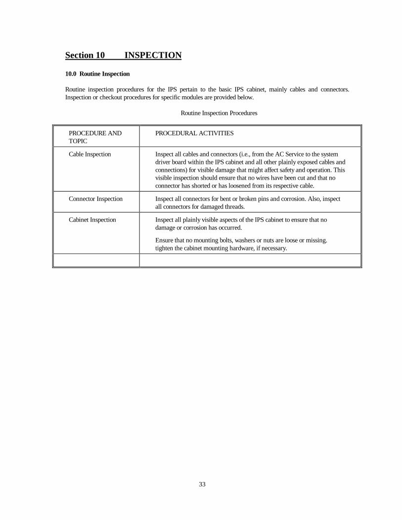
10.0 Routine Inspection
Routine inspection procedures for the IPS pertain to the basic IPS cabinet, mainly cables and connectors.Inspection or checkout procedures for specific modules are provided below.
Routine Inspection Procedures
PROCEDURE ANDTOPIC
PROCEDURAL ACTIVITIES
Cable Inspection Inspect all cables and connectors (i.e., from the AC Service to the systemdriver board within the IPS cabinet and all other plainly exposed cables andconnections) for visible damage that might affect safety and operation. Thisvisible inspection should ensure that no wires have been cut and that noconnector has shorted or has loosened from its respective cable.
Connector Inspection Inspect all connectors for bent or broken pins and corrosion. Also, inspectall connectors for damaged threads.
Cabinet Inspection Inspect all plainly visible aspects of the IPS cabinet to ensure that nodamage or corrosion has occurred.
Ensure that no mounting bolts, washers or nuts are loose or missing.tighten the cabinet mounting hardware, if necessary.
APPENDIX
Siren Command Definitions
Command Function___________________________________________________________________________00H Clear Clears any event in progress.01H Wail Tone Warning.02H Attack Tone Warning.03H Alert Tone Warning.04H Public Address Live Public Address.05H Air-Horn Tone Warning.06H Hi-Lo Tone Warning.07H Whoop Tone Warning.08H Wail-2 (noon test) Tone Warning, short tone.09H North Positioning command to North.0AH East Positioning command to IPSt.0BH South Positioning command to South.0CH West Positioning command to West.0DH Clockwise Positioning command to increment 45° clockwise.0EH Counter clockwise Positioning command to increment 45° counter-clockwise.0FH Silent test Initiates the diagnostic Silent Test, producing a Status response.10H Clear Clears any event in progress.11H Message 13 Initiates digital voice message 13, for an RSDVM module.12H Message 14 Initiates digital voice message 14, for an RSDVM module.13H Message 15 Initiates digital voice message 15, for an RSDVM module.14H Message 16 Initiates digital voice message 16, for an RSDVM module.15H Rotor position Rotor/speaker position request.16H Counter Tone activation software counter request.17H Clear counter Clears the software tone activation counter to zero.18H Arm system Arms the Instant Status response.19H Dis-arm system Disables the Instant Status response.1AH Siren on Enables the tone generator and digital voice.1BH Siren off Disables the tone generator, digital voice is active.1CH Signal/Noise Req. Executes the Signal to Noise check in a Remote Siren.1DH Signal/Noise Status Signal to Noise reading request.1EH Test Clear Clears LEDs1FH Status Request Retrieves the Status byte.
20H Clear Clears any event in progress.21H Battery/AC Requests battery voltage and AC voltage mIPSurements.22H Battery/Temperature Requests battery voltage and cabinet temp. mIPSurements.23H Instant Status Get real time (instant) status of Remote Siren Station.24H Transmit Off Disables the transmit repeat feature during Instant Status.25H Strobe Test StrobeVisor™ only. 4 to 5 flash test period.26H not used27H Wind Shift Greatest directional shift, on a sliding 10 minute window.28H Reset Wind & Temp. Resets the wind and temperature values.29H Reset Rainfall Resets the rainfall value.2AH Weather Requests outside temperature, wind direction, wind speed, and rainfall.2BH Temperature Requests cabinet temperature, outside temperature, low peak, and high peak
(peak values since last reset).2CH Wind Requests wind direction, speed, and peak (peak value since last reset).2DH Rainfall Requests totalized rainfall since last reset.2EH Humidity Requests the humidity reading.2FH Barometer Requests the barometric pressure.
continued......
30H Clear Clears any event in progress.31H Message 1 Initiates digital voice message 1, for an RSDVM module.32H Message 2 Initiates digital voice message 2, for an RSDVM module.33H Message 3 Initiates digital voice message 3, for an RSDVM module.34H Message 4 Initiates digital voice message 4, for an RSDVM module.35H Message 5 Initiates digital voice message 5, for an RSDVM module.36H Message 6 Initiates digital voice message 6, for an RSDVM module.37H Message 7 Initiates digital voice message 7, for an RSDVM module.38H Message 8 Initiates digital voice message 8, for an RSDVM module.39H Strobe On Activates the Strobe Light3AH Strobe Off De-activates the Strobe Light3BH Message 9 Initiates digital voice message 9, for an RSDVM module.3CH Message 10 Initiates digital voice message 10, for an RSDVM module.3DH Message 11 Initiates digital voice message 11, for an RSDVM module.3EH Message 12 Initiates digital voice message 12, for an RSDVM module.3FH Active Status Requests multiple system status parameters
NOTES:
Commands 09 to 0F are only for rotating sirens, such as the WPS-4000 Series.Commands 1C and 1D apply to factory installed radio transceiver systems only.Command 27 to 2F to be used only with a factory supplied weather station.Commands 39 and 3A used only with a factory supplied strobe light or StrobeVisor.Command 3F, Moscad use only.
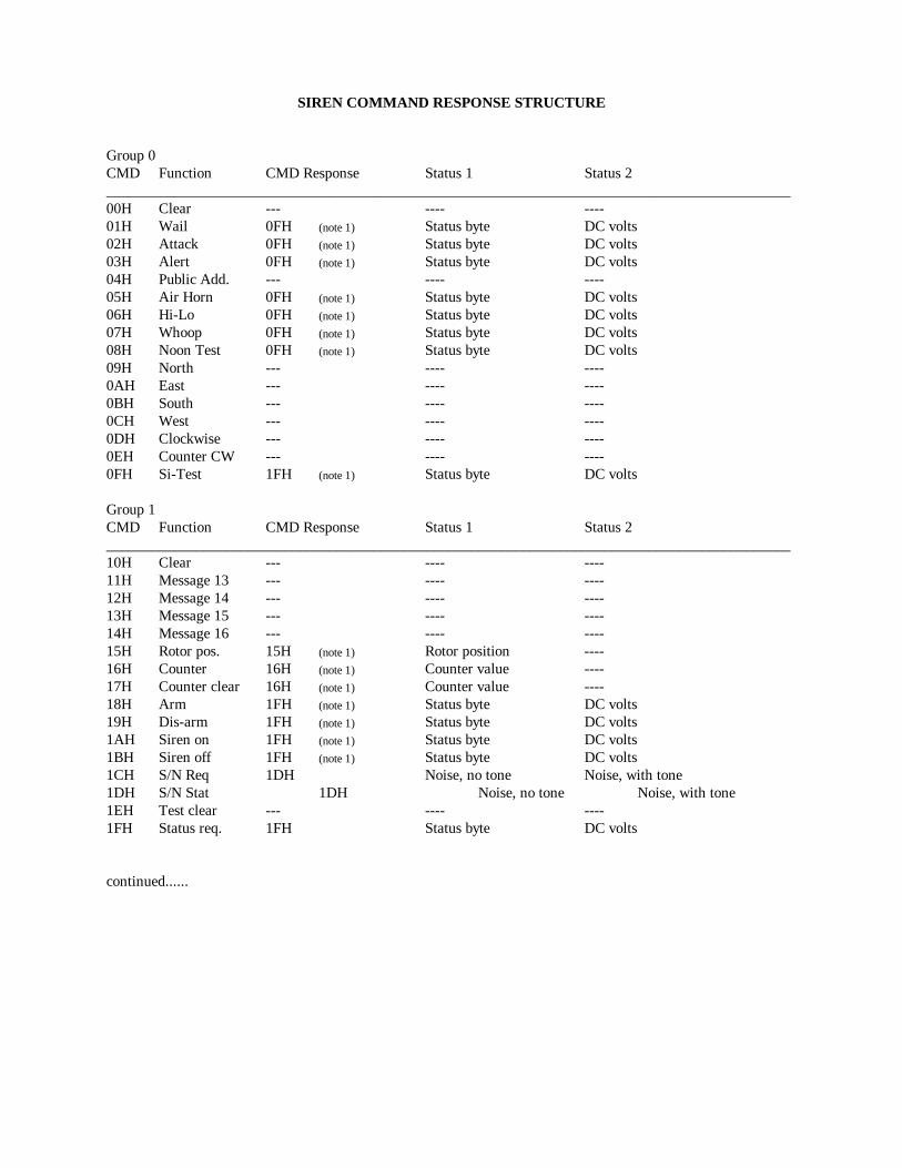
SIREN COMMAND RESPONSE STRUCTURE
Group 0CMD Function CMD Response Status 1 Status 2____________________________________________________________________________________________00H Clear --- ---- ----01H Wail 0FH (note 1) Status byte DC volts02H Attack 0FH (note 1) Status byte DC volts03H Alert 0FH (note 1) Status byte DC volts04H Public Add. --- ---- ----05H Air Horn 0FH (note 1) Status byte DC volts06H Hi-Lo 0FH (note 1) Status byte DC volts07H Whoop 0FH (note 1) Status byte DC volts08H Noon Test 0FH (note 1) Status byte DC volts09H North --- ---- ----0AH East --- ---- ----0BH South --- ---- ----0CH West --- ---- ----0DH Clockwise --- ---- ----0EH Counter CW --- ---- ----0FH Si-Test 1FH (note 1) Status byte DC volts
Group 1CMD Function CMD Response Status 1 Status 2____________________________________________________________________________________________10H Clear --- ---- ----11H Message 13 --- ---- ----12H Message 14 --- ---- ----13H Message 15 --- ---- ----14H Message 16 --- ---- ----15H Rotor pos. 15H (note 1) Rotor position ----16H Counter 16H (note 1) Counter value ----17H Counter clear 16H (note 1) Counter value ----18H Arm 1FH (note 1) Status byte DC volts19H Dis-arm 1FH (note 1) Status byte DC volts1AH Siren on 1FH (note 1) Status byte DC volts1BH Siren off 1FH (note 1) Status byte DC volts1CH S/N Req 1DH Noise, no tone Noise, with tone1DH S/N Stat 1DH Noise, no tone Noise, with tone1EH Test clear --- ---- ----1FH Status req. 1FH Status byte DC volts
continued......
Group 2CMD Function Response Status 1 Status 2 Status 3 Status 4_______________________________________________________________________________________________20H Clear --- ---- ---- ---- ----21H Battery/AC 21H (note 1) Batt DC volts AC volts ---- ----22H Batt./Temp. 22H (note 1) Batt DC volts Cabinet temp ---- ----23H Instant Status 23H Instant Stat DC volts ---- ----24H Transmit off --- ---- ---- ---- ----25H Strobe Test --- ---- ---- ---- ----26H not used --- ---- ---- ---- ----27H Wind shift 27H (note 1) Direction Time Speed Time28H Reset wind --- ---- ---- ---- ----
Group 3CMD Function Response Status 1 Status 2 Status 3 Status 4____________________________________________________________________________________________30H Clear --- ---- ---- ---- ----31H Message 1 --- ---- ---- ---- ----32H Message 2 --- ---- ---- ---- ----33H Message 3 --- ---- ---- ---- ----34H Message 4 --- ---- ---- ---- ----35H Message 5 --- ---- ---- ---- ----36H Message 6 --- ---- ---- ---- ----37H Message 7 --- ---- ---- ---- ----38H Message 8 --- ---- ---- ---- ----39H Strobe On --- ---- ---- ---- ----3AH Strobe Off --- ---- ---- ---- ----3BH Message 9 --- ---- ---- ---- ----3CH Message 10 --- ---- ---- ---- ----3DH Message 11 --- ---- ---- ---- ----3EH Message 12 --- ---- ---- ---- ----3FH Active Status 3FH Active Cmd AC Volts DC Volts Status
Note 1 - No response if the Immediate Response (SW 7 on Dip Switch 1) on the Remote Siren Stationelectronic controller is in the disable position. Also, the tone run-time must be greater than 6seconds for a Status Response.
Bit 0 = Full 1 = All amps/drivers pass, 0 = 1 or more amps/drivers fail.Bit 1 = Partial 1 = 1 or more amps/drivers pass, 0 = all amps/drivers fail.Bit 2 = Rotor 1 = Rotor incremented, 0 = rotor failure.Bit 3 = Stored AC 1 = AC voltage on during tone, 0 = AC voltage off during tone.Bit 4 = Siren On 1 = Tone generator active, 0 = tone generator inactive.Bit 5 = System Armed 1 = Instant Status response is active, 0 = Instant Status inactive.Bit 6 = System Power Up 1 = System power up, AC on, DC good, 0 = system power down, AC off or low
DC.Bit 7 = Dynamic AC 1 = AC volts on, 0 = AC volts off.___________________________________________________________________________
Voltage Definitions
DC volts = 0 to 35 volts, 0 to 255 decimal, 00 to FF Hex.AC volts = 0 to 255 volts, 0 to 255 decimal, 00 to FF Hex.___________________________________________________________________________
Instant Status Breakdown
The data that is present at the Instant port at the time of any Instant Status response. The Instant Statusresponse can operate in a number of different ways. In its simplest form, an Instant Status response follows anInstant Status command (23H) from a Central Control Station. An Instant Status response can also be initiated by an action within a Remote Siren Station, if Switch position 6on Dip Switch 1, on the ESC-864 electronic controller is in the "On" position. Any change in the state of any bit inthe Instant Status byte will cause an Instant Status response to occur. In this case, however, Dip Switch 2 on theESC-864 electronic controller must be understood. Each bit in the Instant Status byte can be disabled by acorresponding switch position on Dip Switch 2. Switch positions on Dip Switch 2 are as follows:
Sw 1 AC voltage On = active, Off = masked.Sw 2 Intrusion On = active, Off = masked.Sw 3 Strobe On = active, Off = masked.Sw 4 not usedSw 5 not usedSw 6 Full On = active, Off = masked.Sw 7 Partial On = active, Off = masked.Sw 8 Bias On = active, Off = masked.
For example, if AC voltage fails and Switch position 1, on Dip Switch 2 is "On", then an Instant Statusresponse will occur. Likewise, if AC voltage fails and Switch 1 is "Off", the Instant Status response will not occur.The Instant Status response is transmitted from a Remote Siren Station 3 times, with 15 seconds betweentransmissions, unless otherwise disabled. The Transmit Off command (24H) will disable the repeat transmissions,if it is issued following the receipt of an Instant Status byte. Typically, Instant Status bytes Full, Partial and Biasare masked off by switches 6, 7, and 8 of Dip Switch 2.
Bit 0 = AC voltage 1 = AC volts on, 0 = AC volts offBit 1 = Intrusion 1 = Cabinet intrusion, 0 = No intrusionBit 2 = Strobe Error 1 = Strobe error, 0 = No strobe errorBit 3 = Supervisor Error 1 = Error, 0 = No errorBit 4 = not used
Bit 5 = Full 1 = All amps/drivers pass, 0 = 1 or more amps/drivers failBit 6 = Partial 1 = 1 or more amps/drivers pass, 0 = all amps/drivers failBit 7 = Bias 1 = Bias line is good, 0 = Bias line failure
The Active Status command (3FH) response is defined as follows:
Active Command = the command that is currently being processed (00H to 3EH).
AC Voltage = voltage at the charger input, 0 to 255 volts, 0 to 255 Dec, 00 to FF Hex.
DC Voltage = battery voltage, 0 to 35 volts, 0 to 255 Dec, 00 to FF Hex.
Status Byte =
Bit 0 = stored FULL data, 0 = fail, 1 = passBit 1 = stored PARTIAL data, 0 = fail, 1 = passBit 2 = present Tone Gen BIAS state, 0 = inactive, 1 = activeBit 3 = present Intrusion state, 0 = door closed, 1 = door openBit 4 = StrobeVisor™ error, 0 = no error, 1 = errorBit 5 = stored Rotor data, 0 = stationary, 1 = oscillatingBit 6 = SuperVisor error 0 = no error, 1 = errorBit 7 = not defined