53
User Manual Supplement 1336 FORCE TM Master/Slave Parallel AC Drive 1000 - 1600 HP
User Manual Supplement
1336 FORCE TM
Master/SlaveParallel AC Drive
1000 - 1600 HP

Important User Information Solid state equipment has operational characteristics differing from those ofelectromechanical equipment. “Safety Guidelines for the Application,Installation and Maintenance of Solid State Controls” (Publication SGI-1.1available from your local Allen-Bradley Sales Office or online athttp://www.ab.com/manuals/gi ) describes some important differences betweensolid state equipment and hard-wired electromechanical devices. Because ofthis difference, and also because of the wide variety of uses for solid stateequipment, all persons responsible for applying this equipment must satisfythemselves that each intended application of this equipment is acceptable.
In no event will the Allen-Bradley Company be responsible or liable forindirect or consequential damages resulting from the use or application ofthis equipment.
The examples and diagrams in this manual are included solely forillustrative purposes. Because of the many variables and requirementsassociated with any particular installation, the Allen-Bradley Companycannot assume responsibility or liability for actual use based on theexamples and diagrams.
No patent liability is assumed by Allen-Bradley Company with respect touse of information, circuits, equipment, or software described in thismanual.
Reproduction of the contents of this manual, in whole or in part, withoutwritten permission of the Allen-Bradley Company is prohibited.
Throughout this manual we use notes to make you aware of safetyconsiderations.
Attentions help you:
• identify a hazard
• avoid the hazard
• recognize the consequences
Important: Identifies information that is especially important for successfulapplication and understanding of the product.
SCANport is a trademark of Rockwell Automation.
PLC is a registered trademark of Rockwell Automation.
COLOR-KEYED is a registered trademark of Thomas & Betts Corporation.
IBM is a registered trademark of International Business Machines Corporation.
Windows 95 is a registered trademark of Microsoft Corporation.
!ATTENTION: Identifies information about practices orcircumstances that can lead to personal injury or death, propertydamage, or economic loss.
Shock Hazard labels may be located on or inside the drive toalert people that dangerous voltage may be present.

Table of Contents
1336 FORCE-5.19 – August, 2000
Table of Contents
Chapter 1 IntroductionManual Objectives ..........................................................................1-1Who Should Use This Manual.........................................................1-1System Overview ............................................................................1-1Drive Configuration..........................................................................1-2Two Phase Modulation....................................................................1-4Motor Configuration.........................................................................1-5Master/Slave Drive Operation .........................................................1-6Electrical Specifications...................................................................1-7Performance Specifications.............................................................1-8
Chapter 2 Mounting and Wiring Your Master/Slave DriveChapter Objectives .........................................................................2-1Before Mounting Your Drive ...........................................................2-2Mounting..........................................................................................2-2Interconnect Cable Connection .......................................................2-2Distance between the Motor and the Drive .....................................2-3Grounding........................................................................................2-3Tach/Encoder Setup........................................................................2-3Common Bus...................................................................................2-3User Enables...................................................................................2-3Fault Signals....................................................................................2-4Motor Setup.....................................................................................2-4PLC Requirements ..........................................................................2-5
Chapter 3 StartupChapter Objectives .........................................................................3-1Safety Precautions ..........................................................................3-1Pre-Energization Checks.................................................................3-2
Drive Inspection ........................................................................3-2Motor Inspection .......................................................................3-2Data Checks .............................................................................3-3Motor Lead Checks...................................................................3-3Inverter Bridge Checks .............................................................3-4Jumper & Dip Switch Checks ...................................................3-4Wire Checks .............................................................................3-4
Power-On Checks ...........................................................................3-5Parameter Setup.......................................................................3-5System Data Block ...................................................................3-6Drive to Drive Interface Data ....................................................3-6Process Trim Block...................................................................3-6Drive Fault Block.......................................................................3-6Velocity Reference Block..........................................................3-7Velocity Regulator Block...........................................................3-7Velocity Feedback Block...........................................................3-7Torque Block Data ....................................................................3-8Inverter Parameters ..................................................................3-8

1336 FORCE-5.19 – August, 2000
ii Table of Contents
Nameplate Motor Parameters...................................................3-9Motor Constants .......................................................................3-9Torque Regulator......................................................................3-9Communication Fault/Alarm .....................................................3-9
Uncoupled Motor Checks................................................................3-9Power On Tests ........................................................................3-9Pre-Enable Verification ...........................................................3-10Master-Transistor Diagnostics ................................................3-11Master-Motor Rotation Phase Test .........................................3-11Voltage Phasing Verification...................................................3-12Slave Transistor Diagnostics ..................................................3-13Slave-Motor Phase Rotation...................................................3-13Rotation Test with both inverters connected...........................3-13
Autotune the 1336 Drive ...............................................................3-14Torque Block Tuning...............................................................3-14Id Measurement Test..............................................................3-15Update Torque Block Gains....................................................3-15Motor Inertia Test....................................................................3-15
Motor Coupled to Mechanical Load Test.......................................3-16Velocity Loop Tuning ..............................................................3-16
Application Setup ..........................................................................3-17Step Response..............................................................................3-17
Filter Setup .............................................................................3-19System Integration ........................................................................3-19Special Commands .......................................................................3-20
Chapter 4 TroubleshootingChapter Objectives .........................................................................4-1Required Equipment .......................................................................4-1Fault LED’s......................................................................................4-2Fault Description .............................................................................4-2Fault Handling .................................................................................4-2
Noise Problems ........................................................................4-2Cable Problems ........................................................................4-2Tach/Encoder Faults.................................................................4-3Stall Delay Problems ................................................................4-3Drive Enable Problems....................................................... 4-3
Main Control Board Test Points ......................................................4-4PLC Comm Board Test Points ........................................................4-5Power Structure Diagnostics ...........................................................4-5
Chapter 5 Encoderless OperationChapter Objectives .........................................................................5-1Application Guidelines.....................................................................5-1Parameter Settings .........................................................................5-2
Appendix A Spare PartsChapter Objectives ........................................................................ A-1Spare Parts .................................................................................... A-1User Parameter Settings................................................................ A-2

1336 FORCE-5.19 – August, 2000
Chapter 1
Introduction
Manual Objectives This document is intended as a supplementary addition to the 1336 FORCE 5.12 User Manual. This supplement covers the additional information you will need to install, program, start up and maintain a 1336 FORCE Master/Slave parallel drive combination.
Who Should Use This Manual This manual is intended for qualified service personnel who have experience setting up and servicing 1336 FORCE AC Drives. You must have previous experience with and a complete understanding of electrical terminology, programming procedures, required equipment and safety precautions before attempting any service on a 1336 FORCE Master/Slave AC Drive.
System Overview The 1336 FORCE Master/Slave Parallel AC Drive uses parallel inverters in applications where the required power is greater than our single largest drive can provide. This 1336 FORCE parallel drive combination is available in 1000, 1300 and 1600 HP versions. Master/Slave drives are available as G or H frame drives in matched 500, 650 or 800 HP combinations. This system utilizes two inverters to supply power to a single motor with two sets of isolated stator windings as illustrated in Figure 1. The inverters are connected to a common converter (common bus) with each inverter operating its own system level functions (communications, precharge etc.).
!ATTENTION: Only qualified personnel familiar with the 1336 FORCE Master/Slave drive system and the associated machinery should plan or implement the installation, start-up, and subsequent maintenance of the Drive. Failure to comply may result in personal injury and/or equipment damage.
ATTENTION: An incorrectly applied or installed Drive can result in component damage or a reduction in product life. Wiring or application errors such as undersizing the motor, incorrect or inadequate AC supply or excessive ambient temperatures may result in damage to the Drive or motor.
ATTENTION: This Drive contains ESD (Electrostatic Discharge sensitive parts and assemblies. Static control precautions are required when installing, testing, servicing or repairing this assembly. Component damage may result if ESD control procedures are not followed. If you are not familiar with static control procedures, reference Allen-Bradley Publication 8000-4.5.2, Guarding Against Electrostatic Damage or any other applicable ESD protection handbook.

1336 FORCE-5.19 – August, 2000
1-2 Introduction
Figure 1.1Master/Slave Drive System Diagram
Drive ConfigurationThe master drive controls the motor current, torque and/or speed utilizing the 1336 FORCE patented field-oriented control and model reference adaptive control. The set-up, commissioning, operation, control and communications all operate in the same manner as a standard 1336 FORCE drive. Both the Master and Slave drives’ utilize an analog carrier-based synchronous current regulator.
(OPTIONAL)

1336 FORCE-5.19 – August, 2000
Introduction 1-3
The Slave drive receives the stationary current commands, speed feedback and PWM carrier reference from the Master drive. Each drive maintains its own system-level communication as well as (enable, start, stop and faults). In this application, each inverter regulates its own current, relying on the current regulator to reject the disturbance presented by the other inverter. With sufficiently high PWM carrier (1.5-2.0 kHz) the current ripple due to this disturbance rejection is acceptably limited. The Master/Slave drives are connected via an interconnect cable providing current references and control information as well as high speed fault protection. Special control boards which are unique to both the Master and Slave allow the Master Drive to control both drives using the standard 1336 FORCE parameter set.
Figure 1.21336 FORCE Model Reference Adaptive Control & Parallel Drive Configuration

1336 FORCE-5.19 – August, 2000
1-4 Introduction
Two-Phase ModulationA control feature specific to the Parallel Drive operation is a two-phase PWM modulator. The parallel drives change from compensated sine-triangle modulation to two-phase modulation at approximately 65% of drive voltage utilization. This extends the stable operating speed range specific to the parallel drives.
Figure 1.31336 Two-Phase Modulation Implementation for Parallel Drives

1336 FORCE-5.19 – August, 2000
Introduction 1-5
Motor Configuration:A custom dual-winding three-phase induction motor is used with the Master/Slave drives. This motor is designed for 0 degrees of phase shift between each of the stator windings (i.e. matched, isolated motor windings in the same slots.). This creates two sets of motor stator windings with a common rotor circuit.
Figure 1.4d-q Motor Model
The effective motor neutral is the same for each stator winding (if wye connected) but the neutrals remain isolated from each other as well as ground.
Figure 1.5Motor Phasor Diagram
Encoder feedback from the motor is connected to the Master drive. Encoder signals are then daisy chained to the Slave drive (note: only the Master drive power supply is used). The encoder signal TE ground is terminated at the Master Only. Both drives are set up with encoder faults enabled, so that any encoder loss will create a drive fault in both Master and Slave drives (only for encoder operation).
1336 FORCE-5.19 – August, 2000
1-6 Introduction
The control function on the Master/Slave unit operates in much the same manner as with a standard 1336 FORCE drive. All control functions are performed through the use of parameters that can be changed with a programming terminal or Drive Tools. Feedback information is derived from hardware devices on the process equipment. Feedback and control signals are provided to the drives via the same adapter boards used on Standard FORCE drives.
All setup and operation information used by the parallel drive unit is stored in a standard FORCE parameter table. In most cases, Slave drive parameter settings are identical to Master drive settings. However, the Slave drive has a predefined group of parameters that require specific settings for parallel operation. Since the Master drive controls the speed, torque, etc. many of the the slave drive parameters are non-functional.
For ease and consistency of setup, we recommend that the non-functional Slave parameters be set the same as the Master. Refer to Chapter 3, Startup, for parameter settings that are exclusive to the Slave drive. Note: Slave parameters P161-165 & P175-180 are set to 0.
Additional LED’s on the main control board labeled “Master” and “Slave” have been added to monitor drive operations. When the Slave Drive is in the ready state, but is not operational the “Slave” LED will blink but the “Enable Slave” LED will be dark. A correctly operating parallel drive unit will have all four operational LED’s illuminated (Slave, Master, Enable Slave, Enable Master).
The drive features, operation and most specifications for Master/Slave drives are the same as their respective G or H frame drive (500 HP through 800 HP). This includes all of the velocity and torque options as well as precharge, power loss ride through, encoderless, overload capability, I/O, fast flux-up, faults and diagnostics. See the following section in this chapter for specifications that are unique to the Master/Slave drive.
1336 Master/Slave Drive Operation:A start sequence should start the Slave drive first, followed by the Master start. The Slave drive will maintain a ready state indefinitely until the Master is started. During the Master start sequence, if both drives do not enable within 1 second, an enable timeout fault will occur. This enable timeout fault is specific only to Master/Slave drives.
A typical stop sequence will disable the master drive first, followed by a shut down of the slave (Never set the Master/Slave drive to stop or disable the Slave drive first).
An external controller should monitor both Master and Slave drives for faults. Any fault should then disable both drives. The controller should also monitor both drive currents (Parameter 264, Motor Current Magnitude Feedback). If an imbalance greater than 25% of rated motor current occurs, the drives should be shut down.

1336 FORCE-5.19 – August, 2000
Introduction 1-7
In parameter 81 (Non-Configurable Fault Status), bit 5 Master/ Slave Cable Loss and bit 6 Master Slave Enable Timeout are specific to the Master/Slave drives. Faults specific to the Master/Slave drives and their probable causes are covered in greater depth in Chapter 4, Troubleshooting.
Specifications Specifications for the Master/Slave version of the 1336 FORCE drive match those of standalone units in the the areas of:
• Control Specs (see publication1336 FORCE 5.12)
• Options (see publication 1336 FORCE 5.12)
• Standard Features (see publication 1336 FORCE 5.12)
• Options (see publication 1336 FORCE 5.12)
• Protective Features (see publication 1336 FORCE 5.12)
• Environmental Specifications (see publication 1336 FORCE 5.12)
• Feedback Devices (see publication 1336 FORCE 5.12)
Areas where the Master/Slave version differs from the standard FORCE drive include:
Electrical Specifications -
• Input Voltage Rating: 380 - 575V (G & H Frame Drives), 3 Phase, +10%, -15% nominal
• Input Power Rating:4-1110 KVA (460V)
4-1156 KVA (500V)
6-1388 KVA (600V)
• Input Frequency: 50/60Hz (+/- 3Hz)
• Standard Output Voltage: Each frame size is line dependent and can power a motor between the following voltages:
G Frame -380 - 480 VAC (line dependent)
500 - 600 VAC (line dependent)
H Frame - 500 - 600 VAC (line dependent)
• Output Current: 5-1346A
• Output Power: 4 - 380 KVA (380 V)
4 - 416 KVA (415V)
4 - 1074 KVA (460V)
4 - 1342 KVA (575V)
• Output Horse Power (Continuous): 1000 - 1600 HP
• Overload Capability: 100% Fundamental current (each standalone inverter)
1 minute - 150% (each standalone inverter)
For example: While the overload capability of the M/S drive does not exceed 150%, it could be viewed as having a 1 minute overload capability, as each drive is capable of 150% for 1 min.
1336 FORCE-5.19 – August, 2000
1-8 Introduction
Note: Since each inverter carries 1/2 of the motor load, in cases where each inverter runs at 150% of the inverter rated load, the motor will run at 150% of the motor rating if the motor and inverters have matched ratings.
2 inverters x (150% load) x 1/2 = 150% of Motor Load.
• Output Frequency Range: 0 -150 Hz
• Efficiency: 97.5% at rated amps, nominal line volts
Performance Specifications -
• Speed Regulation to 0.001% of top speed.
• Torque Regulation to +/- 5 % of rated motor torque.
• Power Loss Ride Thru capability of 2 seconds (each standalone inverter).
• Flying Start: Capable of starting into a spinning motor.
• Torque Linearity: 1%
• Overload Capability: 200% of motor or 150% of inverter rated current whichever is less.
• Programmable Accel-Decel rates from 0 to 6553 seconds.
• Current Limit programmable from 200% of rated output current.
NOTE: M/S Current Loop Bandwidth and Velocity Loop Bandwidth maximum values are 1/2 the values for a standalone FORCE drive.

1336 FORCE-5.19 – August, 2000
Chapter 2
Mounting and Wiring Your 1336 FORCE Master/Slave Drive
Chapter Objectives Chapter 2 provides information so that you can install your 1336T Master/Slave drive.
Important: Some of the mounting and wiring information is specific to the individual frame sizes. This information is identified in the 1336T User Manual (1336 FORCE 5.12).
This topic: Starts on page:
Before mounting your drive 2-2
Interconnect Cable Connection 2-2
Distance between Drive and Motor 2-3
Grounding 2-3
Encoder Setup 2-3
Common Bus 2-3
User Enables 2-3
Fault Signals 2-4
Motor Setup 2-4
Drive Enable 2-6
PLC-Requirements 2-7
!ATTENTION: The following information is merely a guide for proper installation. The National Electric Code (NEC) and any other governing national, regional, or local code will overrule this information. Allen-Bradley cannot assume responsibility for the compliance or noncompliance to any code, national, local, or otherwise, for the proper installation of this drive or associated equipment. A hazard of personal injury and/or equipment damage exists if codes are ignored during installation.

1336 FORCE-5.19 – August, 2000
2-2 Mounting and Wiring Your 1336 FORCE Master/Slave Drive
Before Mounting Your Drive Before mounting your drive, consider the following:
• what tools and equipment you need to mount your drive
• the distance between the motor and the drive
• the distance between the drive and other surfaces
MountingThe Slave drive is intended to be mounted adjacent to the Master drive. Both the Master and the Slave drive should be located near the converter (common bus supply).
Mounting clearances for 1336 FORCE Master/Slave Drives are the same as the requirements for standard G and H frame drives. Refer to Chapter 2 of the 1336T User Manual (1336 FORCE 5.12) for guidelines on mounting and heat dissipation requirements.
Interconnect Cable ConnectionThe interconnect cable which runs from the TB12 and TB13 connectors on the Master Main Control Board to the TB12 and TB13 connectors on the Slave Main Control board should be pre-installed and routed thru a ferrite core on the top of each cabinet. Check that this cable is connected at both ends and routed correctly thru the ferrite cores before starting the drive. A disconnected cable will cause a drive fault at power-up.
If a new interconnect cable is either installed or replaced on-site, the length of the new or replacement cable must Not exceed 10 ft.
TB12
TB10
J5
J7TB11
5V 12V
5V 12V1 2 3
1 2 3
J3
J4
Master
EN VP CP
TB13
J1
Main Control Board (Master Drive)
TB12
TB10
J5
J7TB11
5V 12V
5V 12V1 2 3
1 2 3
J3
J4
Slave
EN VP CP
TB13
J1
Main Control Board (Slave Drive)
InterconnectCable
FerriteCore
EncoderCable

1336 FORCE-5.19 – August, 2000
Mounting and Wiring Your 1336 FORCE Master/Slave Drive 2-3
Distance Between the Motor and the DriveDistance requirements for motor cables on a 1336T Drives are the same as with a standard G or H frame FORCE Drive. Follow the recommendations in Chapter 2 and Appendix A of the 1336 FORCE User manual on motor cable size, type and cable termination issues.
Grounding
Grounding for the 1336 FORCE Master/Slave Drive is primarily the same as for a standard G or H unit. Ground the Master and the Slave independently following the recommendations in Chapter 2 of the FORCE User Manual and in the Motor Setup instructions in this chapter.
Note: Encoder grounding varies slightly from the standard drive in relation to cable shield grounding. Follow the recommendations in the Encoder Setup instructions in relation to cable shield grounding for the Slave drive.
Note: Grounding for the Dual winding induction motor is covered in the Motor Setup section in this chapter.
Encoder Setup
Encoder signals should be run to the Master Drive Main Control Board TB10. From the master drive, the A, A Not, B and B Not signals should be daisy chained to the slave drive with twisted, shielded pairs. The encoder wiring should be routed with the Interconnect cable through the ferrite cores at the top of each cabinet.
The encoder faults MUST be enabled for both drives (i.e. parameter 88, bit 0 set) for encoder operation. Terminate the shields at the Master drive only. DO NOT terminate the shields at the Slave drive.
Common Bus
The DC Bus is critical and must be hard wired between the two drives. The Master and Slave drives must be set up for common bus (or shared bus) operation. Each drive should have its own precharge circuit.
EncoderA
A
B
B
+12 V
Common
Shield
TB107
6
5
4
3
1
2
Master
To
TB10Slave Drive
Drive
1336 FORCE-5.19 – August, 2000
2-4 Mounting and Wiring Your 1336 FORCE Master/Slave Drive
User Enables
The hardware user enables (jumper J8 on the PLC Comm Board) must be set identically on both the Master and Slave drives. Set jumper J8 to either 24V or 120V (depending on your application) on both drives.
Fault Signals
The external fault signals must be interconnected between the master and slave drives.
Motor Setup
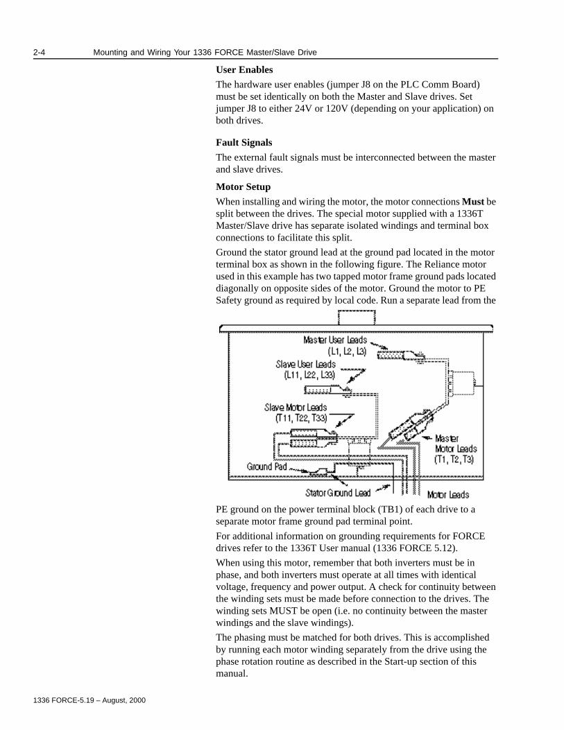
When installing and wiring the motor, the motor connections Must be split between the drives. The special motor supplied with a 1336T Master/Slave drive has separate isolated windings and terminal box connections to facilitate this split.
Ground the stator ground lead at the ground pad located in the motor terminal box as shown in the following figure. The Reliance motor used in this example has two tapped motor frame ground pads located diagonally on opposite sides of the motor. Ground the motor to PE Safety ground as required by local code. Run a separate lead from the
PE ground on the power terminal block (TB1) of each drive to a separate motor frame ground pad terminal point.
For additional information on grounding requirements for FORCE drives refer to the 1336T User manual (1336 FORCE 5.12).
When using this motor, remember that both inverters must be in phase, and both inverters must operate at all times with identical voltage, frequency and power output. A check for continuity between the winding sets must be made before connection to the drives. The winding sets MUST be open (i.e. no continuity between the master windings and the slave windings).
The phasing must be matched for both drives. This is accomplished by running each motor winding separately from the drive using the phase rotation routine as described in the Start-up section of this manual.
1336 FORCE-5.19 – August, 2000
Mounting and Wiring Your 1336 FORCE Master/Slave Drive 2-5
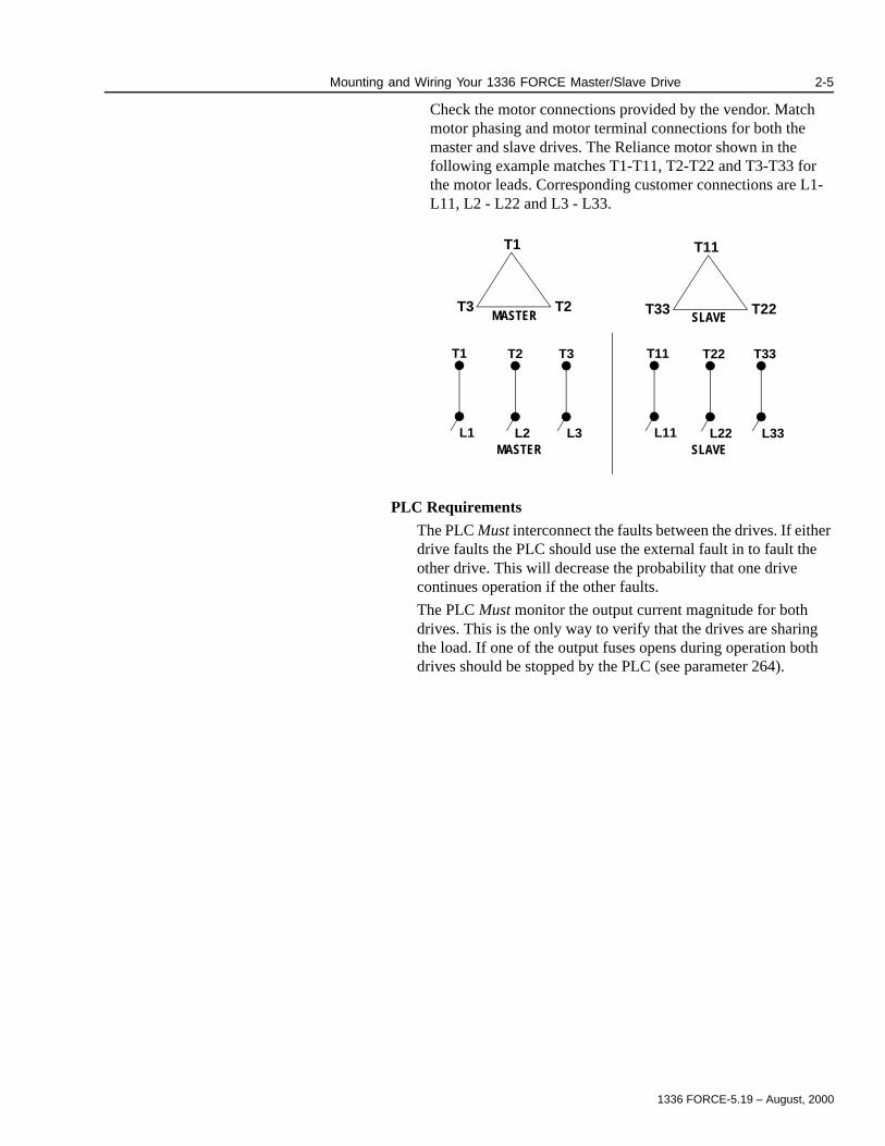
Check the motor connections provided by the vendor. Match motor phasing and motor terminal connections for both the master and slave drives. The Reliance motor shown in the following example matches T1-T11, T2-T22 and T3-T33 for the motor leads. Corresponding customer connections are L1-L11, L2 - L22 and L3 - L33.
PLC Requirements
The PLC Must interconnect the faults between the drives. If either drive faults the PLC should use the external fault in to fault the other drive. This will decrease the probability that one drive continues operation if the other faults.
The PLC Must monitor the output current magnitude for both drives. This is the only way to verify that the drives are sharing the load. If one of the output fuses opens during operation both drives should be stopped by the PLC (see parameter 264).
MASTER SLAVE
T1
T2T3
MASTER
T11
T22T33
T1 T2 T3
L1 L2 L3SLAVE
T11 T22 T33
L11 L22 L33

1336 FORCE-5.19 – August, 2000
2-6 Mounting and Wiring Your 1336 FORCE Master/Slave Drive
This Page Intentionally Blank
1336 FORCE-5.19 – August, 2000
Chapter 3
Startup
Chapter Objectives Chapter 3 describes the procedure for proper startup and tuning of a 1336 FORCE Master/Slave Parallel Inverter AC drive. The procedures covered in this chapter include:
Safety Precautions
This Topic: Starts on Page:
Pre-Energization Checks 3-2
Power-On Checks 3-5
Parameter Setup 3-5
Uncoupled Motor Checks 3-10
Transistor Diagnostics - Master Drive 3-11
Motor-Phase Rotation Test - Master Drive 3-11
Voltage Phasing Verification 3-12
Transistor Diagnostics - Slave Drive 3-13
Motor Phase Rotation - Slave Drive 3-13
Rotation Test (Both Inverters) 3-13
Autotuning 3-14
Motor Inertia Test 3-15
Motor Coupled to Load Test 3-16
Application Setup 3-17
Step Response Check 3-17
System Integration 3-19
Special Commands 3-20
!ATTENTION: Hazard of Electric Shock exists in this drive. Power circuits are optically isolated from control driver circuits. Power circuit components are “floating” with respect to “ground”. Use only approved methods of isolating test equipment when making measurements in power circuits.
!ATTENTION: Only qualified personnel familiar with the 1336 FORCE AC Drive and its associated machinery should plan and implement the installation, startup and subsequent maintenance of the 1336 FORCE Master/Slave drive. Failure to comply may result in personal injury and/or equipment damage.

1336 FORCE-5.19 – August, 2000
3-2 Startup
Pre-Energization Checks Drive Inspection - Check the cabinets for any foreign objects such as metal filings or metal foil, remove any debris.
Verify all connections are tight and connectors are properly seated.
Verify that TE and PE grounding is per supplied Allen-Bradley drawings.
Motor Inspection - Check that the motor is bolted to the frame and the frame is secured. Verify that the motor frame is grounded.
Check that the motor is uncoupled and coupling is secure and won’t be damaged when rotating shaft. Turn the motor by hand to check for binding.
Inspect motor junction box to verify it is clean and free of foreign objects. Verify the connections are tight. Verify thermalguard wiring if used.
Inspect encoder mechanical installation and verify encoder wiring. Make sure the encoder alignment is correct. If a magnetic (e.g. LakeShore) encoder is used, verify that the receiver heads are not touching the encoder rotor.
!ATTENTION: Working with energized industrial control can be hazardous. Severe injury or death can result from electrical shock, burn, or unintended actuation of controlled equipment. Hazardous voltages may exist in the cabinet even with the circuit breaker in the off position. Multiple sources of power may be connected to this drive. Recommended practice is to disconnect and lock out control equipment from power sources, and discharge stored energy in capacitors (if present), before coming in contact with any equipment in this cabinet. During startup it will be necessary to work in the vicinity of energized equipment. The Safety Related Practices of NFPA 70E, “Electrical Safety For Employee Workplaces” must be followed at all times. DO NOT work alone on energized equipment!
!ATTENTION: This Drive contains ESD (Electro-Static Discharge) sensitive devices. Static control precautions are required when installing, testing, servicing or repairing this assembly. If you are not familar with static control procedures, before servicing, reference Allen-Bradley Publication 8000-4.5.2 Guarding against Electrostatic Damage or any other applicable ESD protection handbook.

1336 FORCE-5.19 – August, 2000
Startup 3-3
Data Checks- Record motor and drive data and settings in the following checklists.
Figure 3.1Nameplate Data
Motor Lead Checks- Disconnect all motor leads from Drive and Motor. Megger to ground and to each other.
A. Measure U - Gnd, V - Gnd and W - Gnd (This will be very high resistance), for both master and slave and record this data.
Data Parameter Setting
Motor Nameplate Horsepower #228 Hp
Motor Base Speed #229 rpm:
Motor Rated Current #230 amps:
Motor Rated Voltage #231 Volts:
Motor Nameplate Frequency #232 Hz:
Number of Motor Poles
(Poles = (120xrated freq.) / Sync. Speed)
#233 #:
Encoder PPR #235 PPR:
Rated Inverter Output Amps #220
Rated Inverter Input Voltage #221
Main Control Board Rev Level:
PLC Comm Board (Optional) Rev Level: Switch Settings:
J5:
J10:
J13:
Standard Adapter Board (Optional) Rev Level: Jumper Settings:
U2:
U3:
U4:
U5:
Encoder Name Plate DataCatalog No.:Serial No.:Series:
Motor Name Plate Data
Serial No.:Series:
Catalog No.:
Drive Name Plate Data
Serial No.:Catalog No.:
Series:
1336 FORCE-5.19 – August, 2000
3-4 Startup
B. Ground each lead one at a time at motor end and check continuity with a meter at the drive end. This must be done to verify drive output phase connections to ensure no leads are swapped from slave to master. (Severe motor damage will occur if leads are swapped.)
C. Connect leads at motor end and megger U (L1 or L11), V (L2 or L22), W (L3 or L33) to ground.
Inverter Bridge Checks- Check the inverter bridge for grounds and shorts.
A. Measure each incoming phase to ground.
B Measure each phase to the DC+ and DC- bridge inputs.
C. Measure DC+ and DC- bridge inputs to ground.
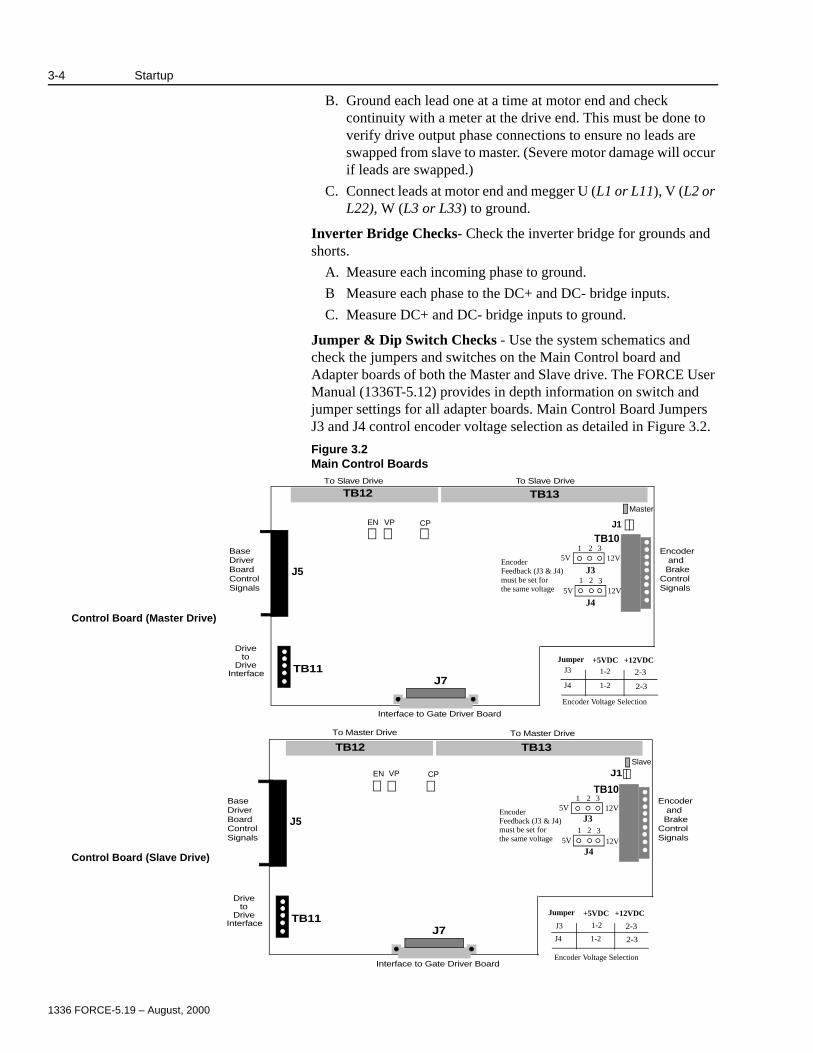
Jumper & Dip Switch Checks - Use the system schematics and check the jumpers and switches on the Main Control board and Adapter boards of both the Master and Slave drive. The FORCE User Manual (1336T-5.12) provides in depth information on switch and jumper settings for all adapter boards. Main Control Board Jumpers J3 and J4 control encoder voltage selection as detailed in Figure 3.2.
Figure 3.2Main Control Boards
Control Board (Slave Drive)
Control Board (Master Drive)
TB12
TB10
J5
J7TB11
EncoderandBrake
ControlSignals
Interface to Gate Driver Board
Driveto
Drive Interface
To Slave Drive To Slave Drive
BaseDriverBoardControlSignals
5V 12V
5V 12V1 2 3
1 2 3
Jumper +5VDC +12VDCJ3 1-2 2-3
J4 1-2 2-3
EncoderFeedback (J3 & J4)must be set forthe same voltage
Encoder Voltage Selection
TB12
TB10
J5
TB13
J1
J7TB11
EncoderandBrake
ControlSignals
Interface to Gate Driver Board
Driveto
Drive Interface
BaseDriverBoardControlSignals
5V 12V
5V 12V1 2 3
1 2 3
Jumper +5VDC +12VDC
J3 1-2 2-3
J4 1-2 2-3
EncoderFeedback (J3 & J4)must be set forthe same voltage
Encoder Voltage Selection
To Master Drive To Master Drive
J3
J4
J3
J4
EN VP CP
Slave
Master
EN VP CP
TB13
J1
1336 FORCE-5.19 – August, 2000
Startup 3-5
Wire Checks - Verify that interconnecting wires to the drive are present, connected and tagged properly. Check particularly:
A. E-Coast Stop circuit.
B. PLC communications
C. That thermalguard wires are used.
D. That any options are correctly wired.
Power-On Checks If an existing Coast Stop is not available or is not functional, it will be necessary to wire in a temporary Coast Stop pushbutton at TB20-1on the Master Drive PLC Comm Adapter Board.
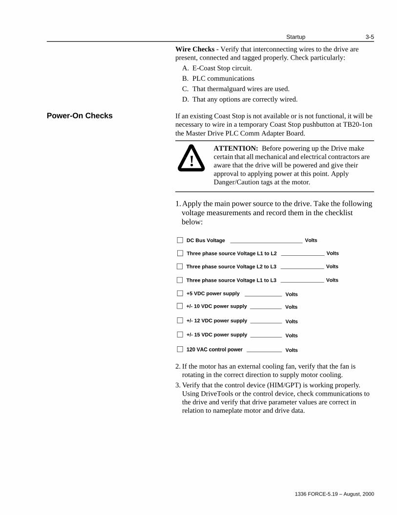
1.Apply the main power source to the drive. Take the following voltage measurements and record them in the checklist below:
2. If the motor has an external cooling fan, verify that the fan is rotating in the correct direction to supply motor cooling.
3. Verify that the control device (HIM/GPT) is working properly. Using DriveTools or the control device, check communications to the drive and verify that drive parameter values are correct in relation to nameplate motor and drive data.
!ATTENTION: Before powering up the Drive make certain that all mechanical and electrical contractors are aware that the drive will be powered and give their approval to applying power at this point. Apply Danger/Caution tags at the motor.
VoltsDC Bus Voltage
VoltsThree phase source Voltage L1 to L2
VoltsThree phase source Voltage L2 to L3
VoltsThree phase source Voltage L1 to L3
Volts+5 VDC power supply
Volts+/- 10 VDC power supply
Volts+/- 12 VDC power supply
Volts+/- 15 VDC power supply
Volts120 VAC control power
1336 FORCE-5.19 – August, 2000
3-6 Startup
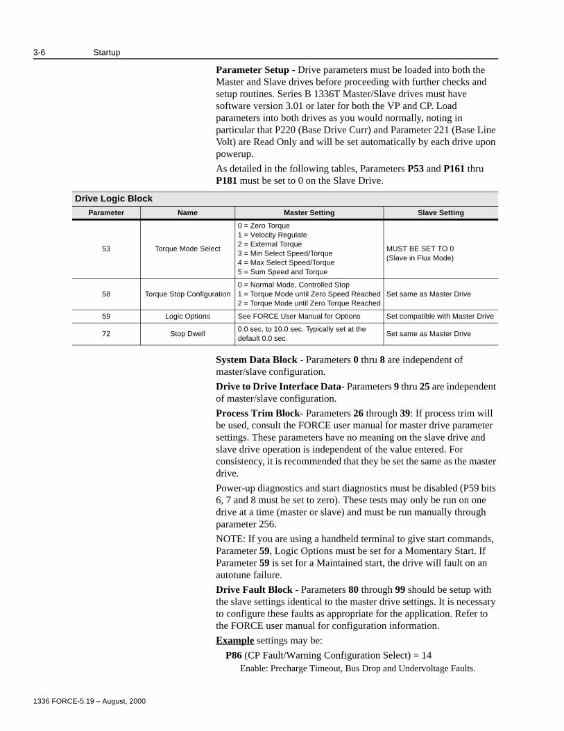
Parameter Setup - Drive parameters must be loaded into both the Master and Slave drives before proceeding with further checks and setup routines. Series B 1336T Master/Slave drives must have software version 3.01 or later for both the VP and CP. Load parameters into both drives as you would normally, noting in particular that P220 (Base Drive Curr) and Parameter 221 (Base Line Volt) are Read Only and will be set automatically by each drive upon powerup.
As detailed in the following tables, Parameters P53 and P161 thru P181 must be set to 0 on the Slave Drive.
System Data Block - Parameters 0 thru 8 are independent of master/slave configuration.
Drive to Drive Interface Data- Parameters 9 thru 25 are independent of master/slave configuration.
Process Trim Block- Parameters 26 through 39: If process trim will be used, consult the FORCE user manual for master drive parameter settings. These parameters have no meaning on the slave drive and slave drive operation is independent of the value entered. For consistency, it is recommended that they be set the same as the master drive.
Power-up diagnostics and start diagnostics must be disabled (P59 bits 6, 7 and 8 must be set to zero). These tests may only be run on one drive at a time (master or slave) and must be run manually through parameter 256.
NOTE: If you are using a handheld terminal to give start commands, Parameter 59, Logic Options must be set for a Momentary Start. If Parameter 59 is set for a Maintained start, the drive will fault on an autotune failure.
Drive Fault Block - Parameters 80 through 99 should be setup with the slave settings identical to the master drive settings. It is necessary to configure these faults as appropriate for the application. Refer to the FORCE user manual for configuration information.
Example settings may be:
P86 (CP Fault/Warning Configuration Select) = 14Enable: Precharge Timeout, Bus Drop and Undervoltage Faults.
Drive Logic BlockParameter Name Master Setting Slave Setting
53 Torque Mode Select
0 = Zero Torque1 = Velocity Regulate2 = External Torque3 = Min Select Speed/Torque4 = Max Select Speed/Torque5 = Sum Speed and Torque
MUST BE SET TO 0(Slave in Flux Mode)
58 Torque Stop Configuration0 = Normal Mode, Controlled Stop1 = Torque Mode until Zero Speed Reached2 = Torque Mode until Zero Torque Reached
Set same as Master Drive
59 Logic Options See FORCE User Manual for Options Set compatible with Master Drive
72 Stop Dwell0.0 sec. to 10.0 sec. Typically set at the default 0.0 sec.
Set same as Master Drive
1336 FORCE-5.19 – August, 2000
Startup 3-7
P87 (CP Warning/None Configuration Select) = 17Enable: Bus Ridethrough Timeout and Bus Drop Cycles Warnings.
P88 (VP Fault/Warning Configuration Select) = 32823Enable: Inverter Overload Trip, Motor Stalled, Motor Overload Trip, Motor OverTemperature Tripped, Inverter OverTemp Pending, and Encoder Feedback Loss Faults.
P89 (VP Warning/None Configuration Select) = 8202P90 (Absolute Overspeed Threshold) = 10% of motor gear in speed
(rpm)Enable: Inverter Overload Pending, Motor Overload Pending, Inverter Overtemp Pending.
P91 (Stall Delay) = 1.0 sec.P92 = (Motor Overload Limit) = 4096 (100% of IQ for 60 sec.)P94 = (Service Factor) = 4096 (1.0)P95 = (Overload Speed 1) = 80% of motor base speed (rpm)P96 = (Motor Overload Speed 2) = 100% of motor base speed
(rpm)P97 = (Minimum Overload Limit) = 4096 (100% current)
With parameters in this configuration, the drive will follow a normal I2T curve.
Velocity Reference Block - Refer to the 1336 FORCE user manual to set Parameters 100 through 126 for the master drive. Parameters 100-126 and Parameters 129-133 do not have meaning on the slave drive, but it is suggested they be set to the same values as the master drive.
Please note the following:
Parameter 102 is a scaling factor that can be used for increased resolution of the speed reference. Typically, drive systems will be set so that a reference of 20,000 units to Parameter 101 will be scaled by Parameter 102 to give an internal speed reference that equates to the gear in speed for that motor. The formula for P102 in this configuration is:
P102 = ((8192 x 4096) /20000) x (gearing rpm/base rpm).
P127 and P128 (motor speed limits reverse and forward) must be compatible on both the master and slave. Normally the slave is set to the same value as the master.
Parameter 131 should set to 0 (no droop) for the local drive testing. When tuning is complete return P131 to the normal droop setting.
Velocity Regulator Block - The settings for Parameters 134 through 142 will be configured during velocity tuning. Parameters 134-142 do not have meaning on the slave drive, but it is suggested they be set to the same values as the master drive.
Velocity Feedback Block - Parameters 143 through 149 are read only. Parameters 151 through 160 will be configured on the master drive during velocity tuning. Parameters 151-160 do not have meaning on the slave drive, but it is suggested they be set to the same values as the master drive.

1336 FORCE-5.19 – August, 2000
3-8 Startup
Parameter 150 (Feedback Device Type) should be set for encoder feedback (P150 = 1) on both the master and slave drive. See Encoderless operation set-up in Chapter 5 for parameter settings specific to encoderless operation.
Torque Block Data - Master Drive parameters in the range from 161 to 181 should be set for the process using the settings detailed in the 1336 FORCE user manual. Slave Drive parameters in this range should be set to zero or their minimum value in most cases. Configurable parameters should be set as detailed in the following table:
Inverter Parameters - Parameters 220 through 227 should be set as follows:
P222 (Inverter Carrier Frequency) can only be set in the master. This parameter has no meaning for the slave but should be set the same as the master for consistency.
Note: Carrier frequency (P222) is horsepower dependent and should be set as follows:Set to 2000 Hz for Drives 500 HP and below.Set to 1500 Hz for Drives greater than 500 HP.Parameters 223 through 226 should be set identically for both the master and slave. Typically the setting for these parameters are left at the factory default.Parameter 227 (CP Options):
Master Drive - For CP 3.04 versions or greater parameter 227 must be set to (0000 0000 0010 0000). For CP3.03 versions or less, Parameter 227 MUST be set to(0000 0000 0010 1000).
Parameter Name Master Setting Slave Setting Notes
161 External Iq Reference Process Setting Must be 0 or minimum
162 External Torque Ref 1 Process Setting Must be 0 or minimum
163 Slave Torque Percent 1Process Setting
Typically = 100%Must be 0 or minimum
164 External Torque Ref 2 Process Setting Must be 0 or minimum
165 Slave Torque Percent 2Process Setting
Typically = 100%Must be 0 or minimum
166 External Torque Step Process Setting Same as Master
174 Minimum Flux Level 25 Same as Master
175 Pos Torque Ref LimitProcess Setting
Typically = 150 or 200Must be 0 or minimum
176 Neg Torque Ref LimitProcess Setting
Typically = -150 or -200Must be 0 or minimum
177 Motoring Power Limit Process Setting Must be 0 or minimum
178 Regen Power Limit Process Setting Must be 0 or minimum
179 Pos Motor Current Ref LimitProcess Setting
Typically = 150 or 200Must be 0 or minimum
180 Neg Motor Current Ref LimitProcess Setting
Typically = -150 or -200Must be 0 or minimum
181 Di/Dt Limit 5 5
1336 FORCE-5.19 – August, 2000
Startup 3-9
Slave Drive - For all versions of CP firmware parameter 227 MUST be set to (0000 0000 1011 1111).
This is necessary for correct operation. Different settings may result in improper drive operation. See engineering for different selections.
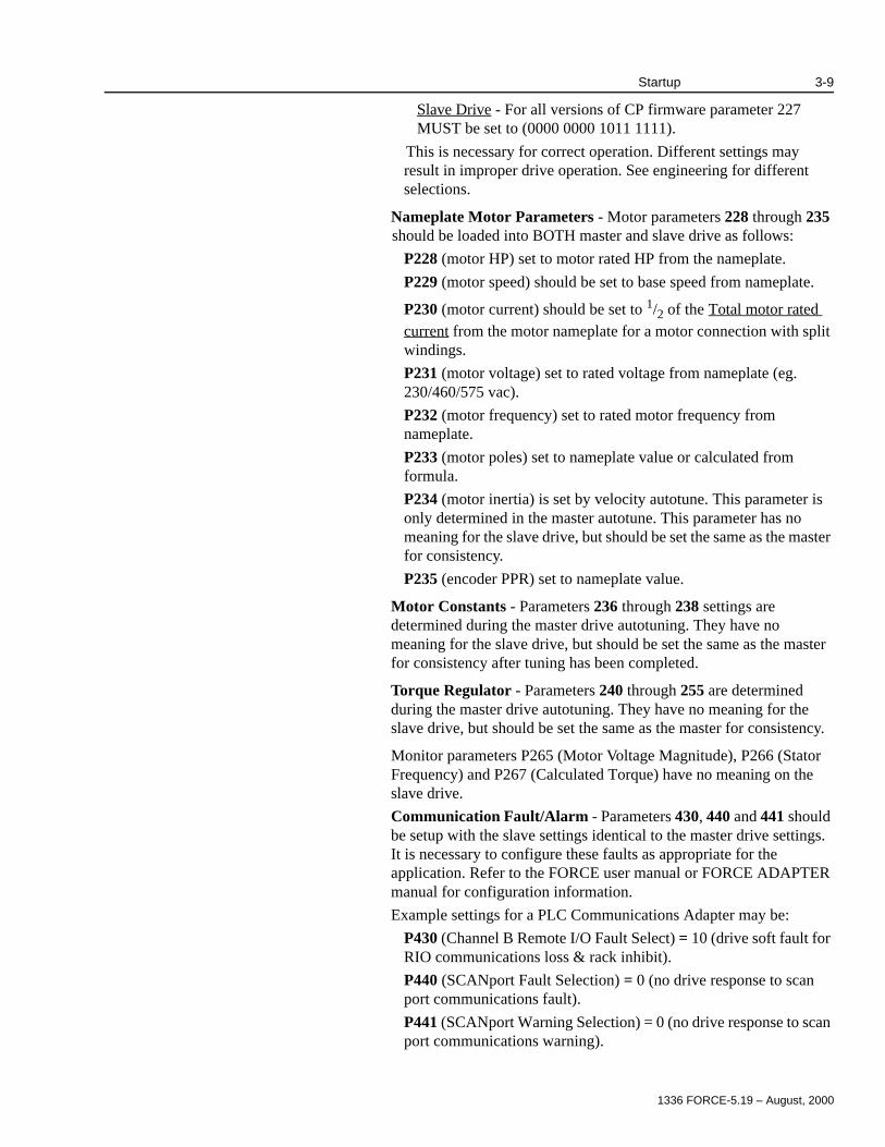
Nameplate Motor Parameters - Motor parameters 228 through 235 should be loaded into BOTH master and slave drive as follows:
P228 (motor HP) set to motor rated HP from the nameplate.
P229 (motor speed) should be set to base speed from nameplate.
P230 (motor current) should be set to 1/2 of the Total motor rated current from the motor nameplate for a motor connection with split windings.
P231 (motor voltage) set to rated voltage from nameplate (eg. 230/460/575 vac).
P232 (motor frequency) set to rated motor frequency from nameplate.
P233 (motor poles) set to nameplate value or calculated from formula.
P234 (motor inertia) is set by velocity autotune. This parameter is only determined in the master autotune. This parameter has no meaning for the slave drive, but should be set the same as the master for consistency.
P235 (encoder PPR) set to nameplate value.
Motor Constants - Parameters 236 through 238 settings are determined during the master drive autotuning. They have no meaning for the slave drive, but should be set the same as the master for consistency after tuning has been completed.
Torque Regulator - Parameters 240 through 255 are determined during the master drive autotuning. They have no meaning for the slave drive, but should be set the same as the master for consistency.
Monitor parameters P265 (Motor Voltage Magnitude), P266 (Stator Frequency) and P267 (Calculated Torque) have no meaning on the slave drive.
Communication Fault/Alarm - Parameters 430, 440 and 441 should be setup with the slave settings identical to the master drive settings. It is necessary to configure these faults as appropriate for the application. Refer to the FORCE user manual or FORCE ADAPTER manual for configuration information.
Example settings for a PLC Communications Adapter may be:
P430 (Channel B Remote I/O Fault Select) = 10 (drive soft fault for RIO communications loss & rack inhibit).
P440 (SCANport Fault Selection) = 0 (no drive response to scan port communications fault).
P441 (SCANport Warning Selection) = 0 (no drive response to scan port communications warning).

1336 FORCE-5.19 – August, 2000
3-10 Startup
Uncoupled Motor Checks Power On Tests - When performing tests in the following section, it will be necessary to open two DriveTools screens, for starting and stopping the Master and Slave drives independently.
Pre-Enable Verification - Apply power to both drives (slave first and then master). Monitor CP software test point #12 (dRam_bus_status) by entering 12 into parameter 273 (Torque Testpoint Selection #1) and then monitoring parameter 274 (testpoint Data #1) on BOTH drives. The least significant bit should be set indicating that precharge has been completed for both drives. The bus voltage measurement should be the same (or close) for both drives. The Master/Slave enable lights should be OFF on both drives.
Monitor CP software test point 15 by entering 15 into parameter 273 (Torque Testpoint Selection #1) and then monitoring parameter 274 (testpoint Data #1). The least significant bit should be cleared for both drives. Bit number 1 should be set for the Master drive and cleared for the Slave drive. This verifies that the firmware has recognized the master & slave control boards.
Parameters should be set so that the slave drive will go into a “flux” mode upon enable. The PLC should enable both drives at the same time, or the slave first followed by the master. When the master drive is enabled, the master drive Enable LED will turn on. When the master drive senses that the slave drive has enabled, the master drive LED will turn on. During normal running, all four LEDs (master, slave, enable master, enable slave) will be turned on.
!ATTENTION: When performing motor checks the following should be observed:
1. Remove all links to the PLC or customer PLC (RIO).
2. Arrange to have representatives from the customer equipped with radio communications watch the powered equipment. Customer representatives must maintain contact with service personnel tuning the equipment. Keep all unnecessary personnel out of the drive and equipment area!
3. Parameters 175 and 176 should be set at less than 25% of their final value as a means of limiting torque to a low level for initial power checks and to avoid possible component damage. During the motor rotation test it may be necessary to raise this value to 75%.
4. Motor rotation will occur when checking motor polarity. If possible, uncouple the motor from the load temporarily.
1336 FORCE-5.19 – August, 2000
Startup 3-11
The slave drive can be kept in the ready state indefinitely. The master drive enable must be completed within 1 second or the drive will fault. This will decrease the probability that one drive continues operation if the other faults.
Master - Transistor Diagnostics - Perform the following steps:
1. Make certain all motor leads are connected correctly at motor end.
2. Connect motor leads at Master drive cabinet only, leave motor leads at Slave drive cabinet safely disconnected and isolated (from each other as well as any ground) as they will have a high voltage potential.
3. Remove the enable for the Slave drive only.
4. Set Autotune/Diagnostics Selection (P256) to 1 in the Master drive (transistor diagnostic).
5. Give the Master drive a start command within 30 seconds of setting Parameter 256. (P368 = 8210)
6. If the Drive faults, check P258 (Inverter Diag. 1) and P259 (Inverter Diag. 2) to determine the failure description.
7. Record values in P260 (Iq Offset)and P261 (Id Offset). Stop the drive.
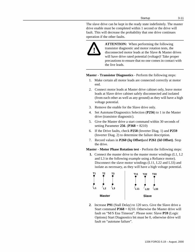
Master - Motor Phase Rotation test - Perform the following steps:
1. Connect the master drive to the master motor windings (L1, L2 and L3 in the following example using a Reliance motor). Disconnect the slave motor windings (L11, L22 and L33) and isolate as necessary, as they will have a high voltage potential.
2. Increase P91 (Stall Delay) to 120 secs. Give the Slave drive a Start command P368 = 8210. Otherwise the Master drive will fault on “M/S Ena Timeout”. Please note: Slave P59 (Logic Options) Start Diagnostics bit must be 0, otherwise drive will fault on “autotune failure”.
!ATTENTION: When performing the following transistor diagnostic and motor rotation tests, the disconnected motor leads at the Slave & Master drives will have drive rated potential (voltage)! Take proper precautions to ensure that no one comes in contact with the live leads.
Master
T1
L1
T2
L2
T3
L3
T11
L11
T22
L22
T33
L33
Slave
1336 FORCE-5.19 – August, 2000
3-12 Startup
3. Set P256 = 2 in the Master drive, and give the Master a start command. Motor should start rotating at this point. The motor may sound and feel rough when running below 3 Hz. You may need to increase the phase rotation frequency ref. (P263) to 4 Hz, and phase rotation current ref. (P262) to 75% to get motor rotation.
4. If motor rotation is incorrect, switch two motor leads. Record phase swapping so the slave can be swapped to match the master connections. If motor rotation is correct (positive) but the speed feedback (P146) is negative, change the encoder signal wires at the motor end.
Verify that Parameter 146 (Speed Feedback) is the same on both Master & Slave drives.
(A) to (B) TB10 7 & 5
(A Not) to (B Not)TB10 6& 4
(B) to (A) TB10 5 & 7
(B Not) to (A Not)TB10 4 & 6
5. With motor turning, and Slave motor leads disconnected, check that all your motor leads and motor windings have the correct phasing between the Master and the Slave:
(The motor will induce voltage in the Slave windings, which should be in phase if wired correctly).
A. Use a voltmeter (Simpson Analog or equivalent) set to DC volts. Measure between (U-master) and (U-slave) motor leads. If phasing between Master and Slave is incorrect, a varying voltage will be present. If phasing is correct, zero voltage will be present.
B. Repeat this test for (V-master and V-slave).
C. Repeat this test for (W-master and (W-slave).
Stop the motor by stopping the Master drive before stopping the Slave. Save your newly entered values to EEPROM.
Voltage Phasing Verification - Verify voltage phasing between the master and slave drives by measuring the motor terminal voltages.
1. Use an oscilliscope to measure the motor terminal voltage on the master and the slave. Measure the master motor differential voltage T1 to T2 and the slave motor voltage T11 to T22. Make sure the polarities between the measurements are the same.
2. Make certain only one set of motor windings are connected (either master or slave, but not both).
3. Run the master drive phase rotation routine. Verify direction of motor rotation and sign of velocity feedback.
!ATTENTION: Motor terminals are at bus potential. Isolated differential probes are recommended when taking this measurement. (x100 probes in differential mode may work).

1336 FORCE-5.19 – August, 2000
Startup 3-13
4. After the motor has reached set speed, using the Drive Enable, disable the drive and measure the decaying motor BEMF as the motor coasts down to zero speed. The phase must be the same on the master and slave motor terminals. If not, rotate phases until they are, and repeat steps 3 and 4.
5. Repeat steps 1 - 4 taking measurements on motor terminal connections T2 to T3 and T22 to T33.
6. Disconnect Master and connect Slave matching any phase changes from Step 4 above.
Slave - Transistor Diagnostics - Perform the following tests:
1. Disconnect the motor leads at the Master drive cabinet. Connect the motor leads in the Slave drive cabinet.
2. Disconnect the enable jumper (J8, PLC Comm) for the Master drive.
3. Set P256 in the Slave drive to bit 1, (Motor Phase Rotation Test).
4. Give the Slave drive a start command.
5. Record values for P260 and P261. Stop the Slave drive.
Slave - Motor Phase Rotation - Perform the following tests:
1. Reconnect the enable jumper in the Master Drive. Set Parameter 59 [Logic Option] bit 6 (Power Up Diag) to 0.
2. Give the Slave Drive a start command.
3. Set Parameter 256 = 2 (Motor Phase Rotation Test) in the Master Drive. Give the Master Drive a start command.
4. The motor should start rotating from the Slave inverter. Check that rotation is in the correct direction.
5. Re-Connect Master so that the Master and Slave motor windings are connected.
Rotation Test with both inverters connected:
1. Connect the motor leads in both the Master and Slave cabinets.
2. Give the Slave drive a start command.
3. Set Parameter 256 = 2 (motor phase rotation) in Master. Give the Master drive a start command.
4. Motor should now start turning using both inverters.
5. Stop the Motor. (Stop the Master drive first, then the Slave.)

1336 FORCE-5.19 – August, 2000
3-14 Startup
Autotune the 1336 Drive
The following parameters (Master Drive) must be set up prior to beginning the Autotune sequence:
1 Must be set to the base speed of the motor when running the torque loop autotune on the 1336T. The motor may not develop enough HP if these parameters are set to other values. After the autotune is complete, P127 and P128 can be set to their correct process limit values.
Torque Block TuningNote: The motor windings for both the master & slave drives must be reconnected before running the Stator Resistance, Leakage Inductance, Id Measurement, Torque block gains and Inertia Tests.The motor must NOT rotate during the Stator Resistance and Leakage Inductance tests or the drive will fault on an autotune failure. If the shaft attempts to rotate, contact Allen-Bradley for suggestions on preventing rotation.Run the Stator Resistance Test:
1. Set Parameter 91 [Stall Delay] in Slave to 120 seconds to allow test completion.
2. Set Parameter 256 [Autotun Diag Sel] = 8 in the Master drive.
3. Start the Slave Drive followed by starting the Master Drive. The test is complete when P256 resets to zero.
4. Save in EEPROM, the measured value for stator resistance can be viewed in Parameter 236 (RS Tune).
5. Repeat test to check validity.
Leakage Inductance Test:
1. Set Parameter 256 [Autotun Diag Sel] to a value of 4.
!ATTENTION: This Autotune sequence is run from the the Master drive only. However both drives require a start signal and will run during autotuning.
When starting the drive, the Slave MUST be started first, then start the Master drive. (If the Master is started without the Slave running, it will cause an M/S Ena Timeout fault after a 1 second delay. This will require a drive RESET!)
When stopping the drive, Stop the Master first, then Stop the Slave.
PARAMETER DESCRIPTION SET TO
141 KF Velocity Loop 65535
40 Auto Tune Torque Limit 85% = 3500 DU
41 Auto Tune Speed 85% = 3500 DU
127 Reverse Speed Limit Base Speed1
128 Forward Speed Limit Base Speed1

1336 FORCE-5.19 – August, 2000
Startup 3-15
2. Start the Slave Drive followed by starting the Master Drive. The test is complete when P256 resets to zero.
3. Save in EEPROM, the measured value for Leakage Inductance can be viewed in parameter 237 (Lsigma Tune).
4. Repeat test to check validity.
Id Measurement Test:
1. Set Parameter 256 [Autotun Diag Sel] to a value of 16.
2. Start the Slave Drive followed by starting the Master Drive. Motor will accelerate toward autotune speed (typically this should occur three separate times). Parameters 240-248 will be updated.
3. The test is complete when Parameter 256 resets to 0.
4. Save in EEPROM, the measured value for Id is in P238 [Base Flux Cur].
5. Repeat to check validity.
Update Torque Block Gains:
1. Set Parameter 256 [Autotun Diag Sel] to a value of 32.
2. Start the Slave Drive followed by starting the Master Drive. Motor will NOT rotate during this test.
3. The test is complete when Parameter 256 resets to 0.
4. Set Parameter 244[Vqe Max] = Parameter 242 [Base Flux Volt].
5. Set the value for Parameter 243 [Vde Max] based on the following table:
6. Save to EEPROM/BRAM.
Motor Inertia Test: You must run this test if your drive will be asked to calculate the velocity regulator gains through autotune.
1. Set Parameter 256 [Autotun Diag Sel] to a value of 64.
2. Start the Slave Drive Followed by Starting the Master Drive. Motor will accelerate toward autotune speed.
3. The test is complete when Parameter 256 resets to 0.
4. The measured value for motor inertia can be viewed in P234 [Motor Inertia].
Run the motor to base speed. Scope the tach feedback to verify proper 50% duty cycle and a phase shift between signals. Record the motor base speed data on the data sheet.
IMPORTANT: Reset parameter 91 [Stall Delay] to application value in Master. Slave Stall Delay may need to be set higher to prevent nuisance trips. Typically 5.0 sec.
Motor Voltage Encoder Encoderless
230V 125 109
460V 250 218
575V 313 273

1336 FORCE-5.19 – August, 2000
3-16 Startup
Motor Coupled to Mechanical Load Test
Prepare the motor for operation by running the following tests:
Verify that the accel (P125) and decel (P126) parameters are set to 10 seconds or greater and the ramp bypass is not enabled. Initiate a normal start command from preset speed 1 (a small value, 5% - 10% of base speed). Based on the machine manufacturer’s recommendations, raise the speed of the driven equipment slowly until 1/2 of rated gearin speed has been reached. Typically, steps of 5% - 10% of base speed are used.
Note: Some new machinery requires a specific“slow crawl” break-in period before operation at normal speeds.
Verify that no mechanical problems are present as the motor and load are accelerated. Based on the machine manufacturer’s recommendations, continue to raise the section speed slowly until gearin speed has been reached using steps of 5% - 10% base speed. Verify that no mechanical problems are present as the motor and load are accelerated. Stop the motor.
Velocity Loop Tuning: Use the following steps to measure the total inertia. (Refer to the 1336 FORCE User manual startup section for additional information).
1. Set Parameter 256 [Autotun Diag Sel] to a value of 128.
2. Start the Slave Drive followed by starting the Master Drive.
3. The measured inertia in seconds can be viewed in Parameter 46 (Total Inertia).
Update the velocity loop gains as follows:
1. Set Kf (P141) to a value of 1 (65535 du)
2. Enter the desired bandwidth in Parameter 43 [Vel Desired BW]
3. Set Parameter 256 [Autotun Diag Sel] to a value of 256.
!ATTENTION: Before you begin this test you MUST confirm the following with the customer to prevent possible machine or motor damage:
1. Motor is coupled to the load.
2. Motor is shimmed and aligned
3. Gearbox and coupling are lubricated
4. Section is lubricated
5. Any required air or water supplies are present
6. Section is ready to run
7. Ventilation for the motors is available
Install hard-wired E-Coast stop buttons at the motor, at process sections and at the programming terminal. Arrange for customer representatives equipped with radio communications to watch driven equipment and communicate with the drive tuner(s). Remove all personnel not involved with the test from the area!
1336 FORCE-5.19 – August, 2000
Startup 3-17
4. Start the Slave Drive followed by starting the Master Drive.
5. The calculated values will appear in Ki (P139), Kp (P140). Save to EEPROM/BRAM.
6. Verify that Parameter 256 (Autotune/Diagnostics Selection) = 0.
Application Setup NOTE: Prior to doing any further application specific programming, the application parameters must be programmed for their final value.
1. Start the drive and run up to base speed. If the section is unstable, the drive may have to be retuned. If necessary, repeat previous autotuning steps to retune the drive for a different radian response (Velocity Loop Tuning).
2. Verify correct speed of drive as follows:
a. Verify that P127 [Rev Speed Limit] and P128 [Fwd Speed Limit]are at process limit values. Verify the correct scaling of speed reference (P102 [Vel Scale Fctr 1]) using the application setup parameter file.
b.Start drive by setting Parameter 368 [SB Analog2 In] = 4114, this will run the drive to the reference set in
Parameter 101 [Velocity Ref 1 Hi]. Hand tach roll at 1/2
gear-in speed to verify calculations. If not correct, check calculations and adjust P102 as necessary. When roll is geared in, record drive gear in data on data sheets.
Note: typically for drive systems, P101 = 20000 units for gear-in speed.
c. Stop the motor. Write parameters to EEPROM and a disk file.
Step Response Set the Velocity Loop Step Response as follows:
1. Connect a chart recorder to analog out 1 and 2 on the comm/standard adapter board.
2. Link velocity feedback (P146 or P269 (series B)) to analog out 1.
3. Link internal Iq ref (P167) to analog out 2 (P388)
4. Set analog out 1 offset (P400) to a value of -2048
5. Set analog out 1 scale (P401) to a value of 32767
6. Set analog out 2 offset (P402) to a value of 0
7. Set analog out 2 scale (P403) to a value of 10291
8. Verify that there is no droop in the drive. Parameter 131 [Droop Percent] should = 0.
9. Enter a value of 8210 into Parameter 367 [SB Analog2 Sel].
This will command the drive to run at preset speed 1 in a forward direction.
10. Enter a value of 2048 (1/2 base speed) into Preset Speed 1 (P119).
11. Enter a 2% Speed Step into external velocity trim (P107).
1336 FORCE-5.19 – August, 2000
3-18 Startup
12. Adjust Ki (P139), Kp (P140), and Kf (P141) to obtain desired response. Reduce kf if needed to control overshoots or help achieve stability.
Note: P141 (Kf) must equal 65535 for web handling systems that require the drive to accurately track a change in reference or in any section that has an outer loop such as a tension loop.
Set the Torque Step Response of the drive as follows:
1. Run the motor RPM up to 1/2 of base speed.
a. Enter a 5-10% torque step into Parameter 166 [Ext Torque Step]. Verify that the speed regulator recovers quickly and is stable. Adjust Ki (P139), if needed to get the desired response.
b.When an acceptable response is achieved, the plot should be saved with all pertinent tuning parameter information recorded on the chart recording. Pertinent information includes speed reference, velocity regulator gains, amount of step, amount of filtering used, section name and date.
c. Write parameters to EEPROM and to a disk file.
Typically, in the paper industry, a minimum of 1 radian response is desired. It is acheived when, after a step input, the speed feedback rises to 63% of the speed step value in a one (1) second duration. Radian = 1/rise time (sec.). The velocity regulator’s integral gain may be raised by increasing KI (P139). As this is accomplished, the rise time will decrease and overshoot will be seen.
If Parameter 139 is set too small, the regulator will be sluggish to load changes. If it is set too large, the regulator will be underdamped, and possibly unstable. Overshoot can be reduced by increasing the proportional gain (P140) or by using feed forward gain (P141). A coordinated drive system should use a value of Kf = 65535, which is a gain of one.
Remember if any gain values are changed, the response (bandwidth) will change. It is best to tune each section of process equipment to get the fastest response from that section without the danger of being close to unstable. The chattering of the gearbox and twisting of the shaft should also be considered. You should NOT detune a section just to get a desired radian response if the section can mechanically handle the faster response. The drive system’s overall response to a change in reference is limited by the response of the slowest section, but it will not hurt the system to have sections with different bandwidth responses.
2. If oscillations occur upon the removal of the speed step, a velocity feedback filter select (P152) may be used. If filtering is used, you may want to increase the velocity bandwidth slightly for a faster response.

1336 FORCE-5.19 – August, 2000
Startup 3-19
Filter Setup- In most applications, a fixed light filter (P152 = 1) or a fixed heavy filter (P152=2) will suffice. If needed, a tunable filter can be implemented.
1. To set up a low pass filter:
a. Set filter select (P152) to a value of 3 which selects lead/lag.
b.Set filter gain (P153) to a value of 0. (Kn = 1 disabled, Kn<1 lag filter, Kn>1 lead filter).
c. Set filter bandwidth (P154) to a value greater than or equal to 10 x the bandwidth of the velocity loop, P43.
d.If you run into backlash noise try setting P152 [Fdk Filt Sel] to a value of 1 or 2.
A speed error filter can be adjusted, but should only be changed from the default in very limited cases. The bandwidth (P142) should be greater than or equal to 10x the bandwidth of the velocity loop. Simply setting the parameter too low can cause the drive to become unstable. Experience has shown that a minimum value for this parameter is in the 50-100 unit range.
2. The motor and load should be accelerated throughout the complete speed range a few times to ensure that instability does not occur.
System Integration 1. With a hand tach, verify the actual surface speed of the section. If software is loaded, adjust PLC roll diameter or gear ratio information as necessary so that the hand held tach and any speed displays agree.
Note: The hand tach is not the best device to measure surface speed, but is a good device to roughly verify calculations. If the system contains an MMI screen, verify that the screen is displaying a proper speed, load and torque values.
2. Verify the operation of tension, position, speed override circuits, or any speed trimming type circuits, and all auxiliary control loops/helper motors.
3. All input/output signals, master-slave relationships, speed and load displays, draw and/or load references, and miscellaneous interactions to external devices/controls should be verified. Run the section from the operator station to verify these items.
4. Items that require the process to be operating for tune-up, such as drooping, should be noted on the “tasks to be completed” form for this section and filed in the Master startup Manual.
5. Drawings should be updated for this section to reflect “As Installed” conditions. Parameters should be saved to EEPROM and documented on paper (a table is supplied in the appendix for this purpose). Chart recording response plots should be filed in the Master startup manual.
1336 FORCE-5.19 – August, 2000
3-20 Startup
Special Commands The following commands can be used for running the drive through DriveTools or a handheld GPT/HIM (see 1336 FORCE User Manual for additional information):
P367{ChA Logic Cmd In}or P368 {ChB Logic Cmd In}= 8208
ACTION: Start from GPT, run at P119 {Preset Speed 1}
P367{ChA Logic Cmd In}or P368{ChB Logic Cmd In} = 8209ACTION: Stop from DriveTools
P367{ChA Logic Cmd In}or P368{ChB Logic Cmd In}= 8210ACTION: Start from DriveTools, run at P119 {Preset Speed 1}
P367{ChA Logic Cmd In}or P368{ChB Logic Cmd In} = 4113ACTION: Stop from DriveTools
P367{ChA Logic Cmd In}or P368{ChB Logic Cmd In} = 4114ACTION: Start from DriveTools, run at P101 {Velocity Reference 1 HI}
1336 FORCE-5.19 – August, 2000
Chapter 4
Troubleshooting
Chapter Objectives Chapter 4 provides information specific to troubleshooting the Master/Slave version of the 1336 FORCE drive. Much of the troubleshooting information that pertains to standalone 1336 FORCE drives can be applied to the Master/Slave drive. Refer to the 1336 FORCE user manual (1336 FORCE-5.12) for tests and diagnostic routines that can be applied to the Master/Slave. The focus of this chapter is on components and tests that are specific to the FORCE Master/Slave units.
Required Equipment For initial troubleshooting, a programming device (or DriveTools) is required to read fault codes. In addition to a programming device, the following should be available before initiating any troubleshooting procedures:
w Digital Multimeter (DMM) capable of 1000V DC/750VAC
w Clamp on Ammeter (AC/DC) with current ratings to 2x rated output current of the 1336 FORCE Master/Slave drive.
w Dual trace oscilliscope with differential capability, digital storage, two X10 and one X100 calibrated probes (optional but recommended).
!ATTENTION: Only qualified personnel familiar with the 1336 FORCE Master/Slave drive system and the associated machinery should perform troubleshooting or maintenance functions on the Drive. Failure to comply may result in personal injury and/or equipment damage.
This Topic: Starts on Page:
Required Equipment 4-1
Fault Descriptions 4-2
Fault Handling 4-2
Testpoints 4-3
Power Structure Diagnostics 4-4
!ATTENTION: Potentially fatal voltages may result from improper useage of an oscilliscope and other test equipment. The oscilliscope chassis may be at potentially fatal voltage if not properly grounded. Allen-Bradley does not recommend use of an oscilliscope to directly measure high voltages. Use an isolated measuring device with a high voltage probe. Contact Allen-Bradley for recommendations.

1336 FORCE-5.19 – August, 2000
4-2 Troubleshooting
w Hand tachometer used to monitor motor velocities.
w Programming Device Instruction Manual and Adapter Board Reference Manuals.
Fault LED’s Two LED’s on the main control board labeled “Master” and “Slave” monitor drive operations. When the Slave Drive is in the ready state, but is not operational the “Slave” LED will blink but the “Enable Slave” LED will be dark. A correctly operating parallel drive unit will have all four operational LED’s illuminated (Slave, Master, Enable Slave, Enable Master).
Fault Description Two hard faults deal exclusively with Master/Slave problems. These faults will result in a solid red D5 LED display on the Main Control Board. All other faults are identical to the Main Control Faults found in Chapter 6 of the 1336 FORCE User Manual 5.12.
The two five digit faults exclusive to the Master/Slave are:
The M/S Cable Loss fault deals with all loss of control signals between the two drives. This could include cable problems, connector problems at TB12 or 13, noise issues that are effecting the control signals, or the shut down of one of the drives.
The M/S Enable Timeout fault usually occurs if an attempt to start the Master drive before the Slave occurs or if there is a failure in the slave enable.
Fault Handling Both Master/Slave faults are hard faults that will shut down the drive upon ocurrence. It will be necessary to read the Fault Que for each separate drive using a programming device to determine which drive initiated the fault, or if the problem originated at the motor or a controlled device. It is Not necessary to unplug the Master/Slave cable to isolate the drives when running tests or diagnostics on the separate drives.
Both of these faults are non-configurable and require a Drive Reset to remove the fault.
Noise Problems - The most common cause of the M/S Cable Loss fault is due to noise problems or TE ground loops. Make certain that TE ground for each drive is isolated from PE. Failure to isolate the ground can create ground loops that initiate this fault. TE/PE connection must be low impedance, typically connecting at the end of the system lineup.
Cable Problems -If the Master/Slave cable itself is suspected of causing an M/S Cable Loss, check the connectors and the separate wires in each connector to make certain they are firmly seated at the screw connections, making good contact at the board and are not damaged.
Fault# LED Fault Type Fault Text Parameter # Bit #
16201 CP, Solid Red Hard M/S Cable Loss 81 05
16022 CP, Solid Red Hard M/S Ena Timeout 81 06

1336 FORCE-5.19 – August, 2000
Troubleshooting 4-3
It is suggested that before attempting a cable replacement, that the main boards be replaced to check the TB12, TB13 connectors. Start with the Main Control board on the Master Drive first and then proceed to the Slave Main Control board before replacing the cable.
When replacing the Master/Slave cable, note the orientation of the cable and the number of wraps as it passes thru the ferrite cores at the top of each cabinet. When checking the wiring between the Master and Slave drives, TB12 and TB13 should be wired 1 to 1. That is pin 1 of TB12 on the Master is wired to pin 1 of TB12 on the Slave and pin 1 of TB13 on the Master to pin 1 of TB13 on the Slave.
Tach/Encoder Faults - It is possible that under certain drive setup configurations, a tach/encoder loss on one drive would allow the master drive to attempt to ride thru the loss of the slave and control the motor alone. A tip off that only the master drive is operational is a cogging sound from the motor as it attempts to run off only one set of windings. If the motor attempts to run using only the master during a fault situation, check the configuration of the tach/encoder loss fault on each drive. The tach/encoder loss fault must be set as operational on both the Master and Slave for encoder operation. (Refer to Chapter 5 for information on Encoderless Operation.)
Stall Delay Problems - If the Stall Delay (Typically 5.0 Sec.) is not set the same for both drives this could cause a Motor Stalled {Parameter 88) fault under certain conditions. Check that Parameter 91 (Stall Delay) is set the same on both drives (typically 5 seconds on a M/S Drive).
Drive Enable Problems - The M/S Enable Timeout can occur if the drives are not started in the correct sequence (Slave first), or if the Master drive enable link with the Slave is not completed within 1 second after the enable is commanded. The Slave drive will indicate that it is enabled and in the ready state when the Slave LED on the Slave Main Control Board begins to blink. If the Master Drive does not enable within 1 second (Master Enable LED will turn on), check that the Slave drive has been set up to enter the “flux” mode upon enable. This can be accomplished by entering a value of 12 in parameter 273 (Testpoint Select #1) and monitoring parameter 274 (Testpoint Data #1) to see if the precharge has been completed on the Slave drive. Bits 8 & 11of parameter 223 (Precharge/Ridethru Select) should also be checked to determine if a fast fluxup is enabled (Bit 8) or whether a precharge exit is being forced (Bit 11).

1336 FORCE-5.19 – August, 2000
4-4 Troubleshooting
Test Points The Hardware testpoints on both the Main Control Board and the PLC Comm Board for both the Master and Slave drives remain the same as for standalone units. The expected output from each testpoint is as follows:
Main Control Board Test PointsTestPoint Application
TP1 DGND
TP2 +5V
TP3 +15V
TP4 AGND
TP5 -15V
TP6 -2.5 to 2.5V
TP7 0 to 2.5V
TP8 +5V when faulted
TP9 CHA Encoder Fdbk 0 to 5 Square Wave with respect to TP1 or TP25 DGND
TP10 Reserved
TP11 Square Wave (Follows Carrier Frequency)
TP12 Reserved
TP13 CHB Encoder Fdbk 0 to 5V Square Wave with respect to TP1 or Tp25 DGND
TP14 Bus Voltage FDBK (4V = 650 vdc)
TP15 Feed Forward Voltage (0 to +/- 7.5V sine wave)
TP16 Ia FDBK (0 to = +/-5V sine wave) same as Iq feedback
TP17 Ic FDBK (0 to = +/-5V sine wave) same as Iq feedback
TP18 Iqs Command (0 to +/- 10V sine wave)
TP19 Ids Command (0 to +/-5V sine wave)
TP20 Master Reset (5V = Reset)
TP21 Id FDBK (0 to +/- 5V sine wave)
TP22 Feed Forward Voltage (0 to +/- 7.5V sine wave)
TP23 ISO 12V for Tachometer/Encoder
TP24 ISO RTN for Tachometer/Encoder
TP25 DGND

1336 FORCE-5.19 – August, 2000
Troubleshooting 4-5
PLC Comm Board Test Points
Power Structure Diagnostics After the initial commissioning of the drives, the Power Structure diagnostics can be run without disconnecting the motor wiring (from either the Master or Slave). Only one drive (Master or Slave) should run the diagnostics at a time. To run the diagnostics, set up the Master drive according to page 3-12 start-up. Issue a start command to only the Master and check results. Repeat the sequence for the Slave.
Testpoint Application
TP1 DGND
TP2 +5V
TP3 +15V
TP4 AGND
TP5 -15V
TP9 Not Used
TP10 Not Used
TP11 ISO +12 VDC
TP12 ISO -5V
TP13 ISO GND
TP14 IGND
TP15 AIN -1
TP16 AIN -2
TP17 AIN -3
TP18 AIN -3
TP19 AIN -4
TP20 +12V
TP21 AOUT - 2
TP22 AOUT - 3
TP23 AOUT - 4
TP24 +10V REF
TP25 -10V REF
1336 FORCE-5.19 – August, 2000
Chapter 5
Encoderless Operation
Chapter Objectives Chapter 5 provides information specific to encoderless operation of the Master/Slave version of the 1336 FORCE drive. This chapter deals with application and parameter requirements that are exclusive to the Master/Slave drive when operated in the encoderless mode. For encoderless tuning and troubleshooting information refer to the 1336 FORCE 5.12 User Manual Appendix A..
Application Guidelines The Master/Slave encoderless operation has all of the same limitations as the normal 1336 FORCE encoderless operation. The maximum velocity bandwidths are lower and continuous operation at speeds below slip speed (1-2 hz typically) should be avoided (other than starting). Starting may require minimum speed limits and a faster acceleration ramp to avoid extended operation in the low speed range. The following should be taken into consideration when making a decision on whether to operate in the encoderless mode:
w Encoderless is applicable when Speed Regulation requirements are greater than +/- 1.0% of base speed. Encoderless may be applicable for regulation between 0.2% and 1.0% with manual adjustments. Encoder operation is recommended below 0.2%.
w Encoderless is applicable when the minimum speed is greater than 1/40 of base speed (i.e. 45 RPM on a 60 Hz, 4 pole motor). Encoderless may be applicable down to speeds of 1/60 of base speed (30 RPM) if high bandwidth responses are not required. Encoder operation is recommended for speeds < 1/60 of base speed (30 RPM).
w The maximum velocity bandwidth achievable with sensorless is approximately twice the default bandwidth value. Bandwidths higher than this may require an encoder because the velocity ripple may be intolerable or there may be stability problems. The maximum bandwidth achievable with sensorless is half the bandwidth achievable with an encoder. Note that the maximum achievable bandwidths decrease with increasing inertia for both encoderless and encoder.
w The starting torque available is the same with encoderless or encoder. Available starting torque is at least 150% motor torque and could be as high as 200% if the inverter can supply the current.
w Minimum (current limit) acceleration and deceleration times are comparable with encoderless and encoder.
This Topic: Starts on Page:
Application Guidelines 5-1
Parameter Setup 5-2

1336 FORCE-5.19 – August, 2000
5-2 Encoderless Operation
w Torque regulation (+/-5%) is comparable with encoderless and encoder at velocities greater than approximately 25% of base speed. At lower speeds encoderless torque regulation may degrade with changing motor temperature.
w Torque response is comparable with both encoderless and encoder (200 Hz).
Parameter Settings Required parameter settings that are unique to Master/Slave Encoderless Operation are:
Master Drive:
1. Parameter 223, Precharge/Ridethru Selection, bit 7 set = 1 (M/S encoderless enable).
2. Parameter 285, Test DAC1 = 74.
3. Parameter 88, VP Fault/Warning Configuration Selection
Bit 0 set = 0, to disable the Encoder Feedback loss fault Bit 5 set = 0, to disable the “motor stalled” fault
4. Parameter 150, Feedback Device Type = 5, (Encoderless velocity estimate with deadband). This should provide a speed range of about 60:1. If a larger speed range is needed, selecting Type = 7, (Encoderless without deadband and low bandwidth) could be considered.
Slave Drive:
1. Parameter 223, Precharge/Ridethru Selection, bit 7 set = 1 (M/S encoderless enable).
2. Parameter 88, VP Fault/Warning Configuration Selection
Bit 0 set = 0, to disable the Encoder Feedback loss fault Bit 5 set = 0, to disable the “motor stalled” fault
3. Parameter 150 = 0 (Encoder Feedback Operation)

1336 FORCE-5.19 – August, 2000
4-6 Troubleshooting
This Page Intentionally Blank

1336 FORCE-5.19 – August, 2000
Chapter 5
Encoderless Operation
Chapter Objectives Chapter 5 provides information specific to encoderless operation of the Master/Slave version of the 1336 FORCE drive. This chapter deals with application and parameter requirements that are exclusive to the Master/Slave drive when operated in the encoderless mode. For encoderless tuning and troubleshooting information refer to the 1336 FORCE 5.12 User Manual Appendix A..
Application Guidelines The Master/Slave encoderless operation has all of the same limitations as the normal 1336 FORCE encoderless operation. The maximum velocity bandwidths are lower and continuous operation at speeds below slip speed (1-2 hz typically) should be avoided (other than starting). Starting may require minimum speed limits and a faster acceleration ramp to avoid extended operation in the low speed range. The following should be taken into consideration when making a decision on whether to operate in the encoderless mode:
w Encoderless is applicable when Speed Regulation requirements are greater than +/- 1.0% of base speed. Encoderless may be applicable for regulation between 0.2% and 1.0% with manual adjustments. Encoder operation is recommended below 0.2%.
w Encoderless is applicable when the minimum speed is greater than 1/40 of base speed (i.e. 45 RPM on a 60 Hz, 4 pole motor). Encoderless may be applicable down to speeds of 1/60 of base speed (30 RPM) if high bandwidth responses are not required. Encoder operation is recommended for speeds < 1/60 of base speed (30 RPM).
w The maximum velocity bandwidth achievable with sensorless is approximately twice the default bandwidth value. Bandwidths higher than this may require an encoder because the velocity ripple may be intolerable or there may be stability problems. The maximum bandwidth achievable with sensorless is half the bandwidth achievable with an encoder. Note that the maximum achievable bandwidths decrease with increasing inertia for both encoderless and encoder.
w The starting torque available is the same with encoderless or encoder. Available starting torque is at least 150% motor torque and could be as high as 200% if the inverter can supply the current.
w Minimum (current limit) acceleration and deceleration times are comparable with encoderless and encoder.
This Topic: Starts on Page:
Application Guidelines 5-1
Parameter Setup 5-2

1336 FORCE-5.19 – August, 2000
5-2 Encoderless Operation
w Torque regulation (+/-5%) is comparable with encoderless and encoder at velocities greater than approximately 25% of base speed. At lower speeds encoderless torque regulation may degrade with changing motor temperature.
w Torque response is comparable with both encoderless and encoder (200 Hz).
Parameter Settings Required parameter settings that are unique to Master/Slave Encoderless Operation are:
Master Drive:
1. Parameter 223, Precharge/Ridethru Selection, bit 7 set = 1 (M/S encoderless enable).
2. Parameter 285, Test DAC1 = 74.
3. Parameter 88, VP Fault/Warning Configuration Selection
Bit 0 set = 0, to disable the Encoder Feedback loss fault Bit 5 set = 0, to disable the “motor stalled” fault
4. Parameter 150, Feedback Device Type = 5, (Encoderless velocity estimate with deadband). This should provide a speed range of about 60:1. If a larger speed range is needed, selecting Type = 7, (Encoderless without deadband and low bandwidth) could be considered.
Slave Drive:
1. Parameter 223, Precharge/Ridethru Selection, bit 7 set = 1 (M/S encoderless enable).
2. Parameter 88, VP Fault/Warning Configuration Selection
Bit 0 set = 0, to disable the Encoder Feedback loss fault Bit 5 set = 0, to disable the “motor stalled” fault
3. Parameter 150 = 0 (Encoder Feedback Operation)

1336 FORCE-5.19 – August, 2000
Appendix A
Spare Parts
Chapter Objectives Appendix A provides the information on 1336 FORCE Master/Slave specific spare parts and a table where user parameter settings for your particular drive application can be recorded for future reference.
Spare Parts In addition to typical spares that are stocked for a stand alone drive, it is recommended that at a minimum at least one set of spare control boards and one interconnect cable be stocked for a master/slave application.
Part numbers for these components are:
# Note: The ferrite core assembly is included with the Interconnect Cable.
This topic: Starts on page:
Spare Parts A-1
User Parameter Record A-2
Component Assembly Part No. Kit Part Number
Interconnect Cable 300087 #
Master Main Control Board
1336T-MCB-SPM51A 74101-699-53 74101-847-13
Slave Main Control Board
1336T-MCB-SPS51A 74101-700-53 74101-847-14
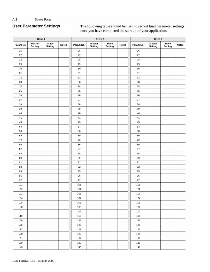
1336 FORCE-5.19 – August, 2000
A-2 Spare Parts
User Parameter Settings The following table should be used to record final parameter settings once you have completed the start up of your application.
Drive 1 Drive 2 Drive 3
Param No. MasterSetting
SlaveSetting Notes Param No. Master
SettingSlave
Setting Notes Param No. MasterSetting
Slave Setting Notes
26 26 26
27 27 27
28 28 28
29 29 29
30 30 30
31 31 31
32 32 32
33 33 33
34 34 34
35 35 35
36 36 36
37 37 37
38 38 38
39 39 39
40 40 40
41 41 41
43 43 43
53 53 53
58 58 58
59 59 59
72 72 72
86 86 86
87 87 87
88 88 88
89 89 89
91 91 91
92 92 92
95 95 95
96 96 96
97 97 97
101 101 101
102 102 102
103 103 103
104 104 104
105 105 105
106 106 106
107 107 107
119 119 119
125 125 125
126 126 126
127 127 127
128 128 128
131 131 131
139 139 139
140 140 140

1336 FORCE-5.19 – August, 2000
Spare Parts A-3
141 141 141
142 142 142
146 146 146
151 151 151
152 152 152
153 153 153
154 154 154
161 161 161
162 162 162
163 163 163
164 164 164
165 165 165
166 166 166
174 174 174
175 175 175
176 176 176
177 177 177
178 178 178
179 179 179
180 180 180
181 181 181
223 223 223
228 228 228
229 229 229
230 230 230
231 231 231
232 232 232
233 233 233
234 234 234
235 235 235
238 238 238
243 243 243
244 244 244
256 256 256
258 258 258
259 259 259
260 260 260
261 261 261
262 262 262
263 263 263
269 269 269
285 285 285
367 367 367
368 368 368
388 388 388
Drive 1 Drive 2 Drive 3
Param No. MasterSetting
SlaveSetting Notes Param No. Master
SettingSlave
Setting Notes Param No. MasterSetting
Slave Setting Notes
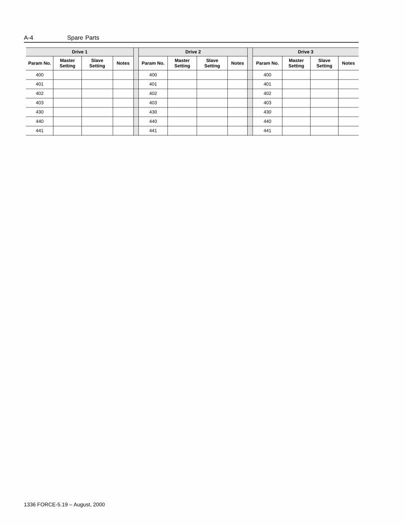
1336 FORCE-5.19 – August, 2000
A-4 Spare Parts
400 400 400
401 401 401
402 402 402
403 403 403
430 430 430
440 440 440
441 441 441
Drive 1 Drive 2 Drive 3
Param No. MasterSetting
SlaveSetting Notes Param No. Master
SettingSlave
Setting Notes Param No. MasterSetting
Slave Setting Notes

Publication 1336 FORCE-5.19 – August, 2000 P/N 304386 (01)Copyright 1999 Rockwell International Corporation. All rights reserved. Printed in USA.
![SIPS: A Framework to Run Serial Algorithms in Parallel ... · al. [6] proposed a multiple master-slave strategy in 'LPFSC'. It is a light weight parallel framework for supercomputing.](https://static.documents.pub/doc/80x56/5d5a289288c993eb6c8bbc42/sips-a-framework-to-run-serial-algorithms-in-parallel-al-6-proposed.jpg)


