1/35 LeTourneau LS CARRYALL scraper assembly. Kit contains some thin, but larger or long parts, some can warp or bend in the box during time period, especially if stored in hotter conditions. It is very easy, but also necessary to fix these before build - simply put them in hot water shortly and let them cool on flat surface like glass. Another way is to lay them on flat surface first and heat them up using a hear dryer. It is also recommended to wash all the parts prior assembly in warm soapy water. Go through assembly guide before you start your work. We recommend to use a sharp scalpel to remove castings blocks carefully, then most of parts will not require any sanding Heat up PE parts with lighter before use, brass will soften and become easy to bend and work with, polish them then with fine sand paper to improve quality and strength of glued joints. Good tool for work with PE will make work much easier, some parts need to be bent with precision to achieve the best looking model. Quality C/A glue is recommended, not cheap supermarket brands. Black Loctite will glue perfectly resin and brass parts, it has long enough set time to fit parts perfectly, and it can also be used to apply big layer around parts and create “welding lines” like looking joints, which will correspond perfectly with appearance of the real thing. You might need to adjust some holes with drilling bits. Otherwise the assembly should be quite easy and straightforward, most parts have “pin to hole” connectors to ensure right placement. Our assembly guide comes as our usual photo guide, we believe in case of resin kits, that real photos can show detailed assembly and exact position of parts much better than any drawings, and PDF file can be zoomed in when needed to see more. Mostly a quick look or fast drawing done on paper will guide you well without need to print most of the pages.
Transcript
1/35 LeTourneau LS CARRYALL scraper assembly.
Kit contains some thin, but larger or long parts, some can warp or bend in the boxduring time period, especially if stored in hotter conditions. It is very easy, butalso necessary to fix these before build - simply put them in hot water shortlyand let them cool on flat surface like glass. Another way is to lay them on flatsurface first and heat them up using a hear dryer.It is also recommended to wash all the parts prior assembly in warm soapy water.Go through assembly guide before you start your work. We recommend to use a sharp scalpel to removecastings blocks carefully, then most of parts will not require any sandingHeat up PE parts with lighter before use, brass will soften and become easy to bend and work with, polish them then with fine sand paper to improve quality and strength of glued joints. Good tool forwork with PE will make work much easier, some parts need to be bent with precision to achieve the bestlooking model. Quality C/A glue is recommended, not cheap supermarket brands. Black Loctite will glue perfectly resinand brass parts, it has long enough set time to fit parts perfectly, and it can also be used to apply big layeraround parts and create “welding lines” like looking joints, which will correspond perfectly with appearanceof the real thing. You might need to adjust some holes with drilling bits. Otherwise the assembly shouldbe quite easy and straightforward, most parts have “pin to hole” connectors to ensure right placement.Our assembly guide comes as our usual photo guide, we believe in case of resin kits, that real photos can show detailed assembly and exact position of parts much better than any drawings, and PDF filecan be zoomed in when needed to see more. Mostly a quick look or fast drawing done on paper willguide you well without need to print most of the pages.
1 23 4
5
6 7 8
x2
x2
x2x2
x5
x2
x2
L+P
9
10 L+P
1112
1314
15L+P
20 L+P
L+P
L+P16
17
1819
21 22 2324
25 26
27 2829
30 31 3233 34 35 36 37
383940
41 x942
43 44 45
46
47
48
x2 x6 x4
PE sheet x2scale rope
43
some kits have hadparts 3+4 cast in onepiece
2
2
35
5
13
21
21
left pulley right double pulley
41 41 41
PE11 PE 12PE13
PE13
PE14
29
29 - assemble in centre to part 5wider offset on the right side
left pulley
right double pulley
8L
8P
assemble parts 8, you might need tosand a little ends which joinraised surface on PE. Tiny excessof glue can help to create an excellentlooking welding lines
PE15
PE2 PE127 (28)
PEhousing
PE1 (PE2)
pre-bend PE parts, then assemble PE2 with 28 and PE1 with 27mind direction of leading eye (PE1 down, PE2 up)
42
PE3 PE4
41 41
prepare PE3 and PE4+ 41
27hole 0,6mm
assemble PE3 first on 5then fit 27 with pulley PE1right above the pulley PE3as shown
assemble PE4 first on 5then fit 28 with pulley PE2right below the pulley PE4as shown. If you want topul ropes through one pulleyto another, drill again hole 0,6mm
PEX
PEX
Use PEX strips to createadditional holders
hole 0,6mm
15
15
1412
647
PE28 pul rope around the raised“drop” on 47 and secure withclamp PE28. Keep about 10cmlength that will be fitted later
6
16L 16P
22L
22P
drill holes (they are marked on the beams) for ropes on bothsides. Pull rope around raised “drop” and through openingto pull around the front pulley and cut as shown below.
place 6 between sides 15, assemble 16L and 16P, and securewith 22L and 22P - now part 6 should be movable, you cankeep it that way or secure with glue in required position
hole 0,6mm
PE28PE32
PEc
make four
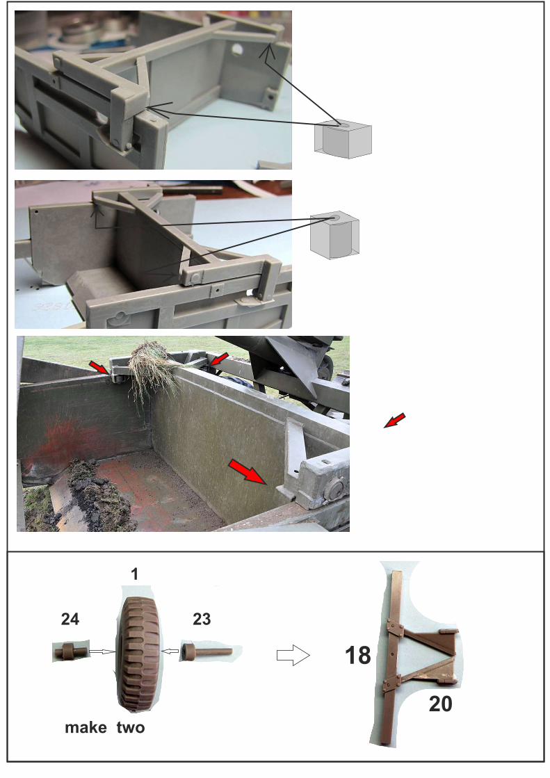
45
20
18
make two
24 23
1
Assemble crossbeam 18 and fit both parts 20 into 12 - controlproperly angle, all 4 housings for wheels and axles have to beone straight against another. Fit the wheels - cut longerinner axle 23 to be about 1mm longer than needed, then pull sidecarefully out a little - to stick outer short axle into the housing onthe scraper side. This way you will get wheels turning for easypainting later. Assemble top fork 17 in holes first, then fit its very end with part 12
18
17
9
40
30
PEa
25
26
PE18
PE17
PE16
make two
42
PE PE19
PE20 (PE19)
43
make two
Dry-fit 25 first and check angleof “wings” with part 18 - next page
Assemble “A” frame 9 between sides,no need to glue yet - fit “wings” onpart 25 in center of beam 18, add part19 and secure all parts nowwith glue (fair amount of glue can againcreate nice welding lines)
19
PEg
46
assemble PEg with pulley 46 and fit onto 19 - there is a line thatshows its position and angle - this pulley is bevelled to the right.Add 48+33, roll some rope around 48 and pull it into slot in 19, thenpull rope from part 47 you assembled earlier around screw onthe right as shown. Assemble 32L and 32P with 31 and glue in place
rope
3348
32L, 32P+ 31
39
PEf
7
38
10P
10L
PEe
Assemble 10R and 10L with 7, addPE strips e (check it fits between thesides), add 38 with length of rope leavingit for later finish as shown. Apron 7 can be assembled closed or opened in any position
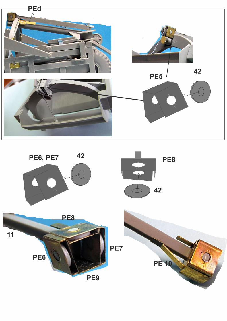
PEd
PE542
PE6, PE7 42
42
PE8
PE6
PE9
PE7
PE8
11
PE 10
rear bottom pulley
44
PE35 PE34
PE33
PE33
PE21
rear top pulley
PE2242
slider bottom pulley PE30 PE29
PE31
PE31
37
44
PE25 PE24
PE26
44
slider top pulley
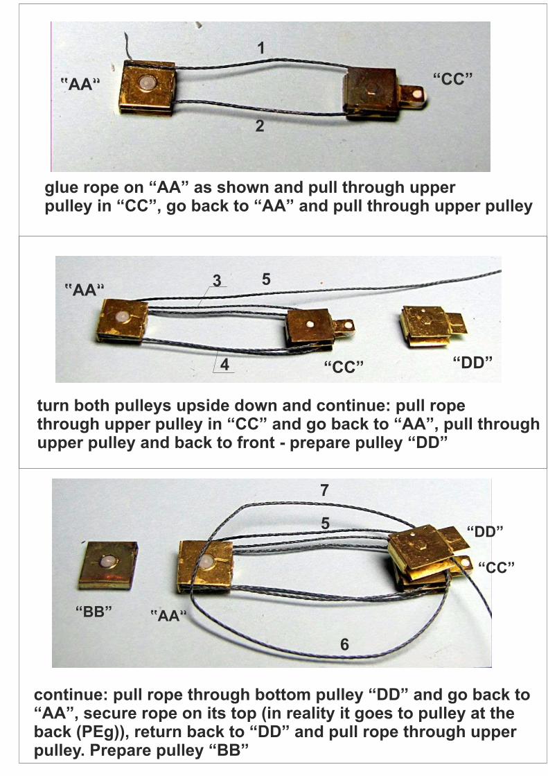
“AA”
“BB”
“CC”
“DD”
“AA” “CC”
1
2
glue rope on “AA” as shown and pull through upperpulley in “CC”, go back to “AA” and pull through upper pulley
3
4
5“AA”
“CC” “DD”
turn both pulleys upside down and continue: pull ropethrough upper pulley in “CC” and go back to “AA”, pull throughupper pulley and back to front - prepare pulley “DD”
“AA”
“CC”
“DD”
“BB”
5
6
7
continue: pull rope through bottom pulley “DD” and go back to“AA”, secure rope on its top (in reality it goes to pulley at theback (PEg)), return back to “DD” and pull rope through upperpulley. Prepare pulley “BB”
“AA” “CC”
“DD”
“BB”
8
9
continue: go to pulley “BB” and pull rope through, leaving itend out for further assembly
cross section views
“AA”L R
“CC” left sidelowered
“CC”L R
“AA”
pull carefully sides of 26 out a little, and put between them “AA”,get it very back resting on innersliders
pull carefully sides of 26 out a little, and put between them “CC”,on the left side pulley middle part is resting on inner slider, whileon right side bottom part is resting on inner slider
cross section view
“AA”L R
“CC”
L R
Place pulley “BB” right abovepulley “AA” on outer slidersvery back
put “DD” pulley on the left side below top slider, while on right side middle part is resting on outer top slider. Place PE27on left top slider and make wire clamp to secure pulley “DD”hung
“BB”
“BB”
pull rope around little front pulley37 and connect both ends intopulleys PE20 and PE19. Thenadd cover PEb
PE20 PE19
PEb
“DD”
“DD”
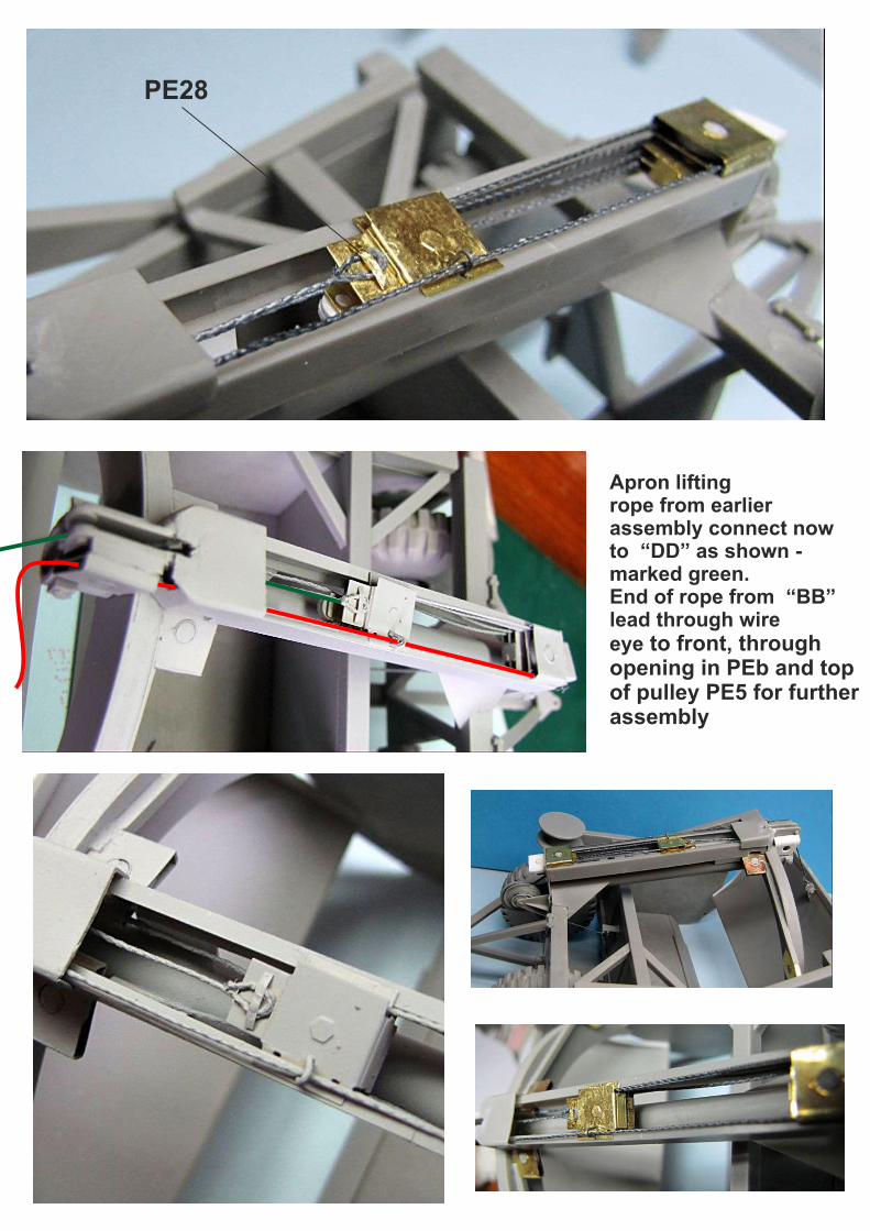
0,5mmwirePE27
PE27
Apron lifting rope from earlierassembly connect nowto “DD” as shown -marked green.End of rope from
to front, throughopening in PEb and topof pulley PE5 for furtherassembly
“BB”lead through wireeye
PE28
34
36
set position of 34 depending ifyou want front straight or turningto the side.Assemble front together with rearAssemble beam 11 with frontpullies to the rest, set positionof whole scraper working orlifted and secure all with glue
11
PE28
2
1
3
1. secure “eye” end of rope with PE28, pull to top of left front pulley2. continue around left front pulley back to bottom rear left pulley3. continue around and to front left top pulley4. continue around and back to top inner rear right pulley5. continue around to front right bottom pulley6. continue around top rear outer right pulley7. continue around leaving the end of rope for further assembly withdriving pulleys
4
5 67
continue with rope throughright front driving pulleys asshown
pull red marked rope from earlier top sliding pulleys assemblythrough front driving pulleys as shown
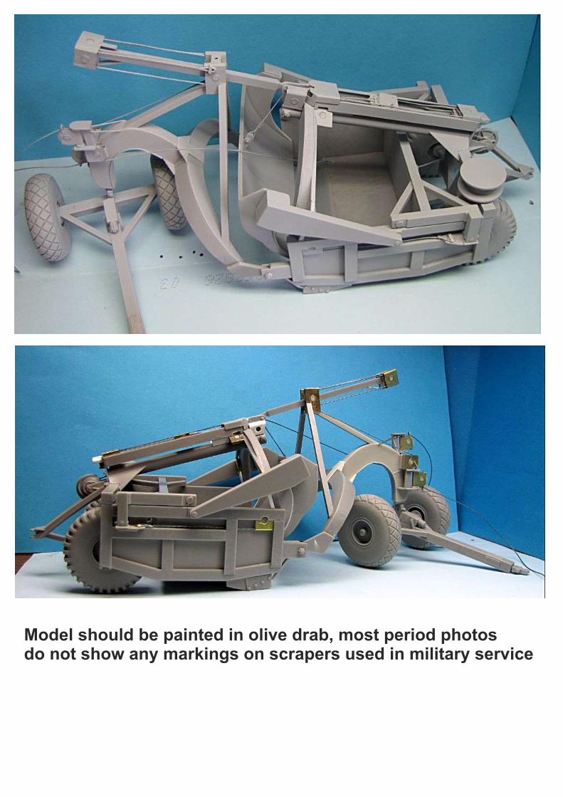
Model should be painted in olive drab, most period photosdo not show any markings on scrapers used in military service