18
MI 022-345 July 1989 Instruction A Siebe Group Company 13A, 13H, or 15A Differential Pressure Transmitters Maintenance
MI 022-345July 1989Instruction
13A, 13H, or 15A Differential Pressure Transmitters
Maintenance
A Siebe Group Company

MI 022-345 – July 1989

NOTEIllustrations show 13A Series transmitters; 13H and 15A Series are similar.
WARNING!When replacing force bar, flexure, capsule gaskets, or base assembly in 13H Transmitter, use only parts specified for 13H list. Failure to do so may expose personnel to risk of serious injury. (Many 13A and 13H parts are physically interchangeable; however, 13H parts are designed to operate at much higher pressures.) It is recommended that whenever the 13H body is opened, the eight nuts and bolts be replaced.
After reconditioning a 13A or 13H, the transmitter must have a hydrostatic pressure test. The recommended test pressure for the 13A is 3000 psi and for the 13H, 9000 psi. If it is not possible to reach the pressure because of equipment limitations or because an unsafe test condition would result, a test pressure 1.5 times the maximum process pressure may be substituted.
The test duplicates the manufacturing plant’s standard procedure on completed transmitters, and is considered a prerequisite to assure safe plant operation.
Normal Maintenance
Transmitter IdentificationIn correspondence with Foxboro, always include the transmitter model and serial numbers.
This data can be found on the identification plate on the high pressure side of the body. See Figure 1.
Figure 1.
Supply Air FilterBlow filter out at least once a day. See Figure 2.
1

MI 022-345 – July 1989 Normal Maintenance
Figure 2.
To Clean Nozzle AssemblyNOTE
An accumulation of dirt at the flapper nozzle may cause a zero shift.
1. Unscrew nozzle nut. Do not let soldered nut on opposite side of casting turn. See Figure 3.
2. Ease nozzle out of casting.
3. Loosen clamp screw and rotate S-clamp. Withdraw nozzle O-ring connection with twisting motion. Do not bend tubing.
Figure 3.
Clean nozzle with 0.76 m (0.030 in) diameter wire, compressed air, or suitable solvent. Wipe top of flapper clean. See Figure 4.
2
Normal Maintenance MI 022-345 – July 1989
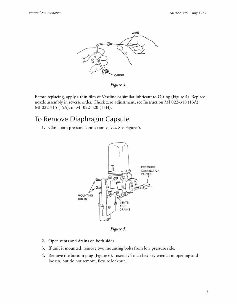
Figure 4.
Before replacing, apply a thin film of Vaseline or similar lubricant to O-ring (Figure 4). Replace nozzle assembly in reverse order. Check zero adjustment; see Instruction MI 022-310 (13A), MI 022-315 (15A), or MI 022-320 (13H).
To Remove Diaphragm Capsule1. Close both pressure connection valves. See Figure 5.
Figure 5.
2. Open vents and drains on both sides.
3. If unit it mounted, remove two mounting bolts from low pressure side.
4. Remove the bottom plug (Figure 6). Insert 1/4 inch hex key wrench in opening and loosen, but do not remove, flexure locknut.
3
MI 022-345 – July 1989 Normal Maintenance
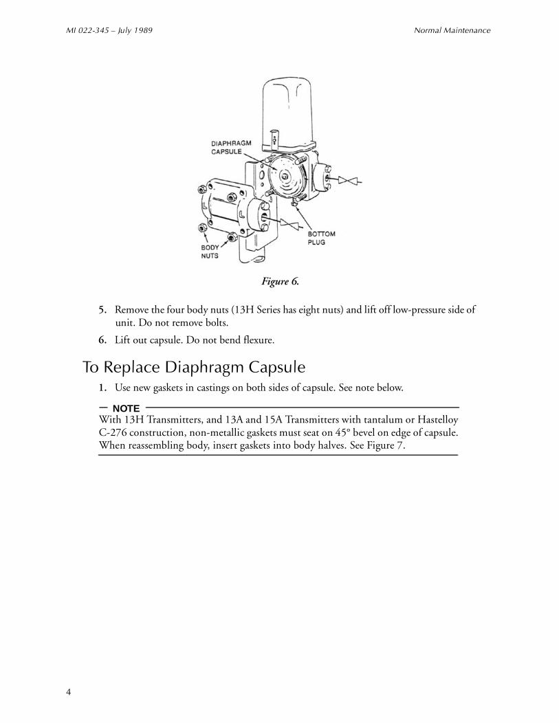
Figure 6.
5. Remove the four body nuts (13H Series has eight nuts) and lift off low-pressure side of unit. Do not remove bolts.
6. Lift out capsule. Do not bend flexure.
To Replace Diaphragm Capsule1. Use new gaskets in castings on both sides of capsule. See note below.
NOTEWith 13H Transmitters, and 13A and 15A Transmitters with tantalum or Hastelloy C-276 construction, non-metallic gaskets must seat on 45° bevel on edge of capsule. When reassembling body, insert gaskets into body halves. See Figure 7.
4

Normal Maintenance MI 022-345 – July 1989
Figure 7.
2. Position capsule in its cavity so that flexure fits on force bar. Align index marks on capsule and body and carefully tighten flexure locknut with wrench. See Figure 8.
Figure 8
3. Replace low-pressure side of unit, tightening the four nuts finger tight. Loosen the flexure locknut and then complete tightening the four nuts gradually and uniformly to 80 to 90 N·m (60 to 65 lb·ft) torque.
4. Replace the remaining parts in reverse order. Make flexure locknut adjustment and then calibrate transmitter (see Instruction MI 022-340).
5

MI 022-345 – July 1989 Normal Maintenance
To Replace Capsule FlexureNOTE
Flexures on high-range capsules (those with “HI” stamped on outer circumference) cannot be replaced.
1. To remove capsule from transmitter, see “To Remove Diaphragm Capsule” section.
2. When removing flexure, clamp capsule in vise. Use protective facing on jaws of vise to protect capsule. See Figure 9.
Figure 9.
3. Use open-end wrench (preferably one shaped to fit base of flexure). See Figure 10.
Figure 10.
4. Tighten flexure to 14 N·m (10 lb·ft) torque. Do not bend flexure.
5. After flexure is replaced, scribe two new index marks on opposite edges of capsule in line with flexure (Figure 11). Use new index marks when reinstalling capsule. Make flexure locknut adjustment (see Instruction MI 022-340).
6
Normal Maintenance MI 022-345 – July 1989
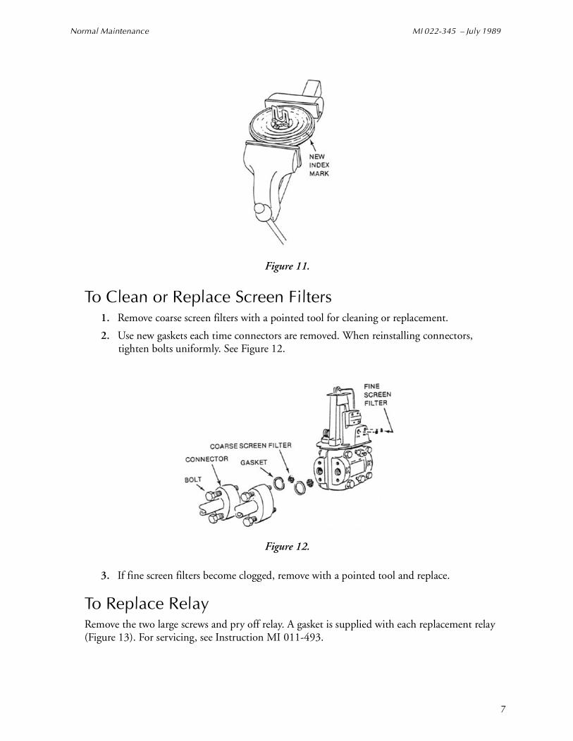
Figure 11.
To Clean or Replace Screen Filters1. Remove coarse screen filters with a pointed tool for cleaning or replacement.
2. Use new gaskets each time connectors are removed. When reinstalling connectors, tighten bolts uniformly. See Figure 12.
Figure 12.
3. If fine screen filters become clogged, remove with a pointed tool and replace.
To Replace RelayRemove the two large screws and pry off relay. A gasket is supplied with each replacement relay (Figure 13). For servicing, see Instruction MI 011-493.
7

MI 022-345 – July 1989 Further Disassembly
Figure 13.
To Clean RestrictorA plugged restrictor will cause low output pressure. Refer to Figure 14 for cleaning procedure.
Figure 14.
1. Unscrew restrictor from top of relay base.
2. Clean with a 0.127 mm (0.005 in) diameter wire (Part 0042527).
3. Before reinstalling, apply a thin film of Vaseline or similar material to O-rings.
NOTEOn earlier models, restrictor was located either under relay or on side of relay base.
Further DisassemblyNormal servicing of the transmitter does not require the removal of any parts other than those already mentioned. Further disassembly is not recommended because of possible loss of accuracy or damage to the transmitter. The following procedures are described for emergency use only. Refer to Figure 15 during these procedures. The item numbers in Figure 15 correspond with the item number in parentheses in the procedure that follows.
8
Further Disassembly MI 022-345 – July 1989
To Remove Feedback Bellows (15) and Zero Spring [Behind Zero Screw (13)]
1. Carefully pry out feedback O-ring connection at relay (see “To Clean Nozzle Assembly” section).
2. Remove the two 7/16 in cap screws (12) holding bracket (11).
3. Unscrew completely zero adjustment screw (13) to release zero spring. Bracket (11) and feedback bellows (15) can now be removed.
4. Remove nut (14) to disconnect feedback bellows from bracket.
5. Remove zero spring by unscrewing it from range rod (16). Be careful not to change alignment on spring clamp.
6. Reverse this procedure to reassemble, making sure that post on bracket is within zero spring alignment clamp. Tighten zero adjustment screw until about 6 mm (0.25 in) of thread remains exposed. When replacing feedback connection, apply a thin layer of Vaseline or similar lubricant to O-ring.
7. Calibrate transmitter (see Instruction MI 022-340).
To Remove Relay Mounting Assembly (5)1. Carefully pry out nozzle and feedback O-ring connections at relay (see “To Clean
Nozzle Assembly” section).
2. Remove relay mounting assembly by unscrewing the two screws (9) above mounting plate and small screw (10) beneath mounting plate.
3. Reverse this procedure to reassemble. When replacing O-ring connections, apply a thin film of Vaseline or similar lubricant to O-rings.
9
MI 022-345 – July 1989 Further Disassembly
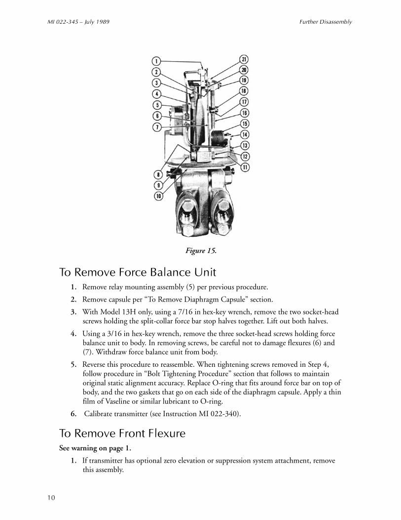
Figure 15.
To Remove Force Balance Unit1. Remove relay mounting assembly (5) per previous procedure.
2. Remove capsule per “To Remove Diaphragm Capsule” section.
3. With Model 13H only, using a 7/16 in hex-key wrench, remove the two socket-head screws holding the split-collar force bar stop halves together. Lift out both halves.
4. Using a 3/16 in hex-key wrench, remove the three socket-head screws holding force balance unit to body. In removing screws, be careful not to damage flexures (6) and (7). Withdraw force balance unit from body.
5. Reverse this procedure to reassemble. When tightening screws removed in Step 4, follow procedure in “Bolt Tightening Procedure” section that follows to maintain original static alignment accuracy. Replace O-ring that fits around force bar on top of body, and the two gaskets that go on each side of the diaphragm capsule. Apply a thin film of Vaseline or similar lubricant to O-ring.
6. Calibrate transmitter (see Instruction MI 022-340).
To Remove Front FlexureSee warning on page 1.
1. If transmitter has optional zero elevation or suppression system attachment, remove this assembly.
10

Further Disassembly MI 022-345 – July 1989
2. Carefully pry out both feedback and nozzle O-ring connections at relay and remove nozzle tubing from casting (1) (see “To Clean Nozzle Assembly” section).
3. Remove relay mounting assembly (5) per previous applicable procedure.
4. Using a 3/32 in hex-key wrench, remove top plate (2) by removing two plate screws (21).
5. Using a 9/64 in hex-key wrench, remove force bar screws (3).
6. Remove cap screws and plates (8) and left front flexure (6) off of dowel.
7. Reverse this procedure to reassemble. If force bar has been removed or force balance unit loosened from body, top of front flexure should be visually lined up with casting (1), so that there is no twist evident in flexures. Then tighten plate screws (21). Do not tighten cap screws (8).
8. Loosen cap screws (12) and force bar screws (3). Apply 1 MPa (150 psi) to both sides of transmitter. Tap body lightly and tighten all screws.
9. Check static alignment (see below).
To Remove Back Flexures (7)Unless front flexure has already been removed, 3/32 in hex-key wrench used in Step 2 must be cut down to fit into the screws (20).
1. Remove 3/16 in cap screws (12) holding bracket (11).
2. Using a 3/32 in hex-key wrench, remove two screws and plates (20) holding back flexures to plate (2), and remove back flexures.
3. Reverse this procedure to reassemble. Do not tighten cap screws (12).
4. Loosen cap screws (8) and force bar screws (2). Apply 1 MPa (150 psi) to both sides of transmitter. Tap body lightly and tighten all screws.
5. Calibrate transmitter (see Instruction MI 022-340).
To Remove Force Bar (4)See warning on page 1.
1. Remove force balance unit per previous applicable procedure.
2. Using a 9/64 in hex-key wrench, remove the two force bar screws (3). Force bar (4) can now be removed. This unit should not be further disassembled; if its diaphragm seal is removed from the force bar, leaks are likely to occur after reassembly. If either force bar or its seal requires replacing, they both should be replaced as a unit.
3. Reverse this procedure to reassemble. Replace O-ring at force bar seal. Before inserting force bar into topworks, lubricate O-ring and top force bar with Vaseline or similar lubricant. Carefully ease force bar into O-ring recess to avoid damaging O-ring.
4. When reassembled, loosen the four cap screws (8) and (12) and two force bar screws (3). Apply 1 MPa (150 psi) to both sides of transmitter. Tap body lightly and tighten all screws.
5. Check static alignment (see below).
11

MI 022-345 – July 1989 Further Disassembly
Static AlignmentThis adjustment is required if front flexure or force bar is replaced.
1. Connect transmitter to an input air supply regulated at a fixed value between 120 and 150 kPa (18 and 22 psi).
2. Check with a 1/4 in hex-key wrench through bottom plug hole that capsule flexure locknut is tightly fastened to force bar. Replace bottom plug.
3. Rotate range wheel (18) to approximate operating position. Tighten locknut (17).
4. Vent both sides of transmitter and adjust zero screw (13) so that output is 20.0 kPa or 3.0 psi.
5. Apply gradually and simultaneously to both sides of transmitter (output must not go off scale), a pressure equal to highest static pressure anticipated during normal operation.
NOTEDo not exceed static pressure limits (see transmitter specifications).
6. After two minutes, observe transmitter output. If output has not changed, static alignment is correct. If output change is more than desired, slowly vent pressure and make static alignment as follows.Loosen the two plate screws (21) and adjust static alignment wheel (19) to bring output back to 20.0 kPa or 3.0 psi. Turn wheel clockwise to lower output. Tighten plate screws (21) after each adjustment of alignment wheel.
7. Remove bottom plug and loosen, then carefully retighten capsule flexure locknut.
8. Repeat Steps 6 and 7 until output change is satisfactory. Calibrate transmitter (see Instruction MI 022-340).
Flapper AlignmentThe flapper is aligned at the factory; a realignment is required only if the force bar balance unit has been disassembled. This alignment procedure requires a 5.31 mm (0.209 in) diameter spacing tool, Part F0105MB, obtainable from Foxboro, a 1/8 in open end wrench, and a small screw-driver. (The wrench and screwdriver are included in tool kit, Part F0101AA, obtainable from Foxboro.)
CAUTION!Use care in turning thin flexure alignment to prevent shearing.
1. If transmitter has optional zero elevation or suppression attachment, remove this assembly.
2. Connect an air supply regulated at a fixed pressure of between 120 and 150 kPa or 18 to 22 psi to input and a 0 to 140 KPa or 0 to 20 psi test gauge output.
3. Loosen flexure locknut at bottom of force bar (see Figure 8).
4. Turn range wheel to top of range rod.
12
Further Disassembly MI 022-345 – July 1989
5. Using spacing tool as feeler gauge, insert tool at lower end of range rod between threaded surface and machine casting surface. Adjust zero screw to get correct spacing for tool.
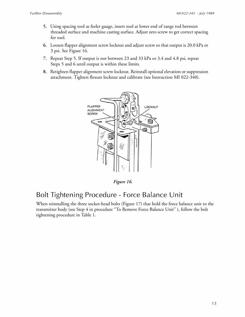
6. Loosen flapper alignment screw locknut and adjust screw so that output is 20.0 kPa or 3 psi. See Figure 16.
7. Repeat Step 5. If output is not between 23 and 33 kPa or 3.4 and 4.8 psi, repeat Steps 5 and 6 until output is within these limits.
8. Retighten flapper alignment screw locknut. Reinstall optional elevation or suppression attachment. Tighten flexure locknut and calibrate (see Instruction MI 022-340).
Figure 16.
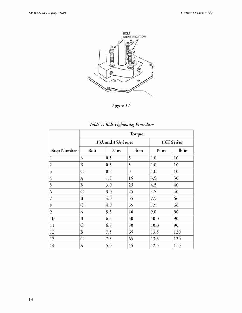
Bolt Tightening Procedure - Force Balance UnitWhen reinstalling the three socket-head bolts (Figure 17) that hold the force balance unit to the transmitter body (see Step 4 in procedure “To Remove Force Balance Unit” ), follow the bolt tightening procedure in Table 1.
13
MI 022-345 – July 1989 Further Disassembly
Figure 17.
Table 1. Bolt Tightening Procedure
Step Number
Torque
13A and 15A Series 13H Series
Bolt N·m lb·in N·m lb·in
1 A 0.5 5 1.0 10
2 B 0.5 5 1.0 10
3 C 0.5 5 1.0 104 A 1.5 15 3.5 30
5 B 3.0 25 4.5 40
6 C 3.0 25 4.5 40
7 B 4.0 35 7.5 66
8 C 4.0 35 7.5 66
9 A 5.5 40 9.0 8010 B 6.5 50 10.0 90
11 C 6.5 50 10.0 90
12 B 7.5 65 13.5 120
13 C 7.5 65 13.5 120
14 A 5.0 45 12.5 110
14

Further Disassembly MI 022-345 – July 1989
15
MI 022-345 – July 1989 Further Disassembly
ISSUE DATES MAY 1984 JUL 1989
The Foxboro Company33 Commercial StreetFoxboro, MA 02035-2099United States of Americahttp://www.foxboro.comInside U.S.: 1-888-FOXBORO
(1-888-369-2676)Outside U.S.: Contact your local Foxboro Representative.Facsimile: (508) 549-4492
A Siebe Group Company
Foxboro is a registered trademark of The Foxboro Company.Siebe is a registered trademark of Siebe, plc.Hastelloy is a trademark of Haynes International.Vaseline is a trademark of Cheseborough Pond’s, Incorporated.
Copyright 1985 - 1999 by The Foxboro CompanyAll rights reserved
MB 100 Printed in U.S.A 0789


