International Journal of Mechanical Engineering and Technology (IJMET), ISSN 0976 – 6340(Print),
ISSN 0976 – 6359(Online), Volume 6, Issue 4, April (2015), pp. 126-133© IAEME
126
DUSTER DETACHING MECHANISM FOR
AUTOMATED MOTORIZED WHITEBOARD
Puneet Mathur1, Bhushan Tukaram Chougule
2, Ravina Raghunath Nangare
3,
Dr. M. S. Rohokale4
1,2,3,4Department of Mechanical Engineering,
Sinhgad Institute of Technology, Lonavala, Maharashtra-410401, INDIA
ABSTRACT
Erasable slates, a cheap but durable substitute for costly paper and ink, had been in use for
centuries. Students could practice reading and writing on their slates anywhere but for larger maps
and writing, blackboards were invented. Like many of the best tools blackboard is a simple machine
but with the innovations in the technology whiteboards are invented for eliminating the diseases
caused by chalk powder used in blackboards. This paper focuses on the design and construction of
automated whiteboard with the mechanism of attaching and detaching the dusters. The system
consists of many small parts and mechanisms which are used efficiently for the working of the
board. Some of them are: - Flexible whiteboard surface material, dusters, plastic rollers, cam and
follower, four bar mechanism and motors. The working of this system is based on rotation of flexible
whiteboard sheet material around the rollers. Rollers are operated by means of motors. When power
is supplied motors start rotating. The whiteboard surface material is rotated through motors and
gets cleaned automatically by the dusters fixed on the backside of the board. In this commutation an
attempt has been made to modify the features of automated motorized whiteboard by introducing a
duster detaching mechanism. Due to this mechanism teacher can use the writings on the board as a
future reference.
Keywords: Automated, Motorized, Detaching, Flexible
1. INTRODUCTION
In early 1800 teachers wanted to offer geography lessons to their students that required larger
maps so they connected number of small slates into a single grand field. This thought of the teachers
INTERNATIONAL JOURNAL OF MECHANICAL ENGINEERING AND
TECHNOLOGY (IJMET)
ISSN 0976 – 6340 (Print)
ISSN 0976 – 6359 (Online)
Volume 6, Issue 4, April (2015), pp. 126-133
© IAEME: www.iaeme.com/IJMET.asp
Journal Impact Factor (2015): 8.8293 (Calculated by GISI)
www.jifactor.com
IJMET
© I A E M E
International Journal of Mechanical Engineering and Technology (IJMET), ISSN 0976 – 6340(Print),
ISSN 0976 – 6359(Online), Volume 6, Issue 4, April (2015), pp. 126-133© IAEME
127
gave the idea of inventing blackboard. Teachers now had a flexible and versatile visual aid. Students
no longer simply listened to the teacher; they had a reason to look up from their desk. With the
growing technology it was observed that allergies and other health risks are occurred due to chalk
boards which demanded the replacement of blackboards with whiteboards [1]. Whiteboards are
analogous to chalkboards allowing rapid marking and erasing of markings on their surface. As time
became an important factor for people innovations in the technology started growing up rapidly. A
lot of time was wasted for rubbing large size blackboards and whiteboards due to which many
innovations were done on whiteboard for proper utilization of time.
2. RELATED WORK
Due to growing need of technology for human comfort continuous researches are carried out
all across the globe. Along with the innovations in the type of whiteboards like rotating whiteboard,
sliding whiteboard etc. cleaning methods used for the board are also modified. Remote control
motorized cleaners are made in which the dusters are operated with the help of remote control [2].
This type of cleaner moves horizontally by means of motor mechanism and erase the board with
the help of dusters attached to it but there are some limitations in above design. The pressure is
to be applied on the moving dusters for proper rubbing of the board and user have to wait till the
cleaner comes to its initial position. These limitations have been overcome by the design of
automated motorized whiteboard in which instead of moving the dusters the whiteboard surface is
moved around the rollers [3]. So there is no need of providing the external pressure on the dusters as
they are already fixed at the rear side of the board with certain amount of pressure. To make the
system more easy to use remote controlled sensors are inbuilt into the system [4]. This mechanism is
used to increase the efficiency of the system as it cleans itself by rotation of whiteboard
surface and the dusters fixed at the rear side of the board by just placing the hand or any
object in front of the infrared sensors placed on the top of the board.
As per the survey for further modifications teachers suggested to introduce a system for using
the written surface as a future reference. This was only possible by detaching the dusters from the
whiteboard surface. To implement this technique criss cross or cam and follower mechanism can be
used. But in large size whiteboards more magnitude of force was required for operating criss cross
mechanism which was practically not possible. Therefore cam and follower mechanism is used to
detach the dusters from the whiteboard surface.
3. SYSTEM DESCRIPTION
The major parts used for construction of system are as follows.
3.1 Wooden block
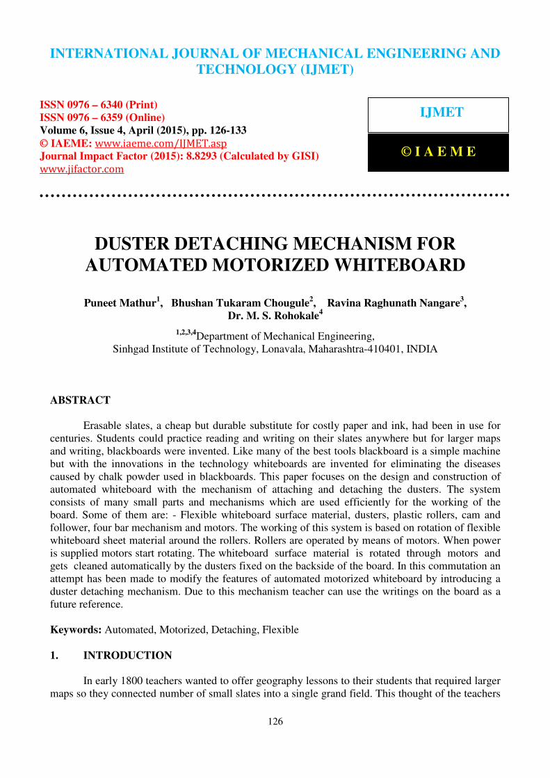
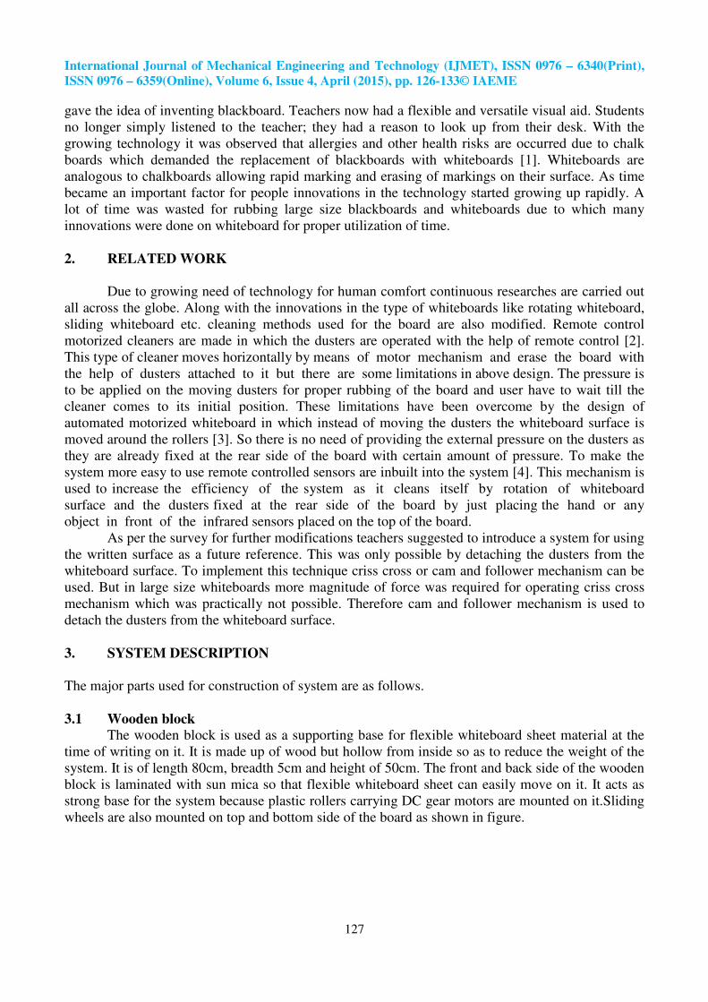
The wooden block is used as a supporting base for flexible whiteboard sheet material at the
time of writing on it. It is made up of wood but hollow from inside so as to reduce the weight of the
system. It is of length 80cm, breadth 5cm and height of 50cm. The front and back side of the wooden
block is laminated with sun mica so that flexible whiteboard sheet can easily move on it. It acts as
strong base for the system because plastic rollers carrying DC gear motors are mounted on it.Sliding
wheels are also mounted on top and bottom side of the board as shown in figure.
International Journal of Mechanical Engineering and Technology (IJMET), ISSN 0976 – 6340(Print),
ISSN 0976 – 6359(Online), Volume 6, Issue 4, April (2015), pp. 126-133© IAEME
128
Figure 1: Sliding wheels installed on base
Figure 2: Wooden block
3.2 Cam and Followers
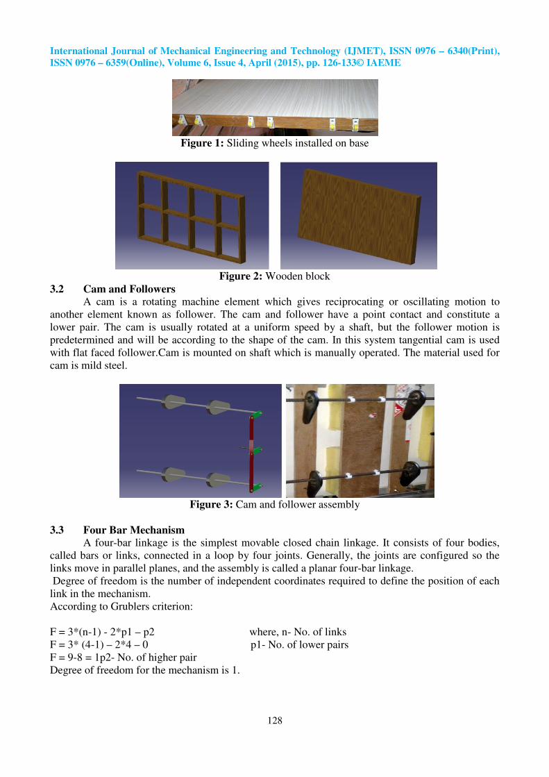
A cam is a rotating machine element which gives reciprocating or oscillating motion to
another element known as follower. The cam and follower have a point contact and constitute a
lower pair. The cam is usually rotated at a uniform speed by a shaft, but the follower motion is
predetermined and will be according to the shape of the cam. In this system tangential cam is used
with flat faced follower.Cam is mounted on shaft which is manually operated. The material used for
cam is mild steel.
Figure 3: Cam and follower assembly
3.3 Four Bar Mechanism
A four-bar linkage is the simplest movable closed chain linkage. It consists of four bodies,
called bars or links, connected in a loop by four joints. Generally, the joints are configured so the
links move in parallel planes, and the assembly is called a planar four-bar linkage.
Degree of freedom is the number of independent coordinates required to define the position of each
link in the mechanism.
According to Grublers criterion:
F = 3*(n-1) - 2*p1 – p2 where, n- No. of links
F = 3* (4-1) – 2*4 – 0 p1- No. of lower pairs
F = 9-8 = 1p2- No. of higher pair
Degree of freedom for the mechanism is 1.
International Journal of Mechanical Engineering and Technology (IJMET), ISSN 0976 – 6340(Print),
ISSN 0976 – 6359(Online), Volume 6, Issue 4, April (2015), pp. 126-133© IAEME
129
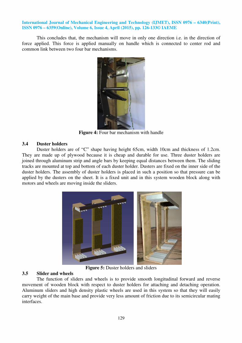
This concludes that, the mechanism will move in only one direction i.e. in the direction of
force applied. This force is applied manually on handle which is connected to center rod and
common link between two four bar mechanisms.
Figure 4: Four bar mechanism with handle
3.4 Duster holders
Duster holders are of “C” shape having height 65cm, width 10cm and thickness of 1.2cm.
They are made up of plywood because it is cheap and durable for use. Three duster holders are
joined through aluminum strip and angle bars by keeping equal distances between them. The sliding
tracks are mounted at top and bottom of each duster holder. Dusters are fixed on the inner side of the
duster holders. The assembly of duster holders is placed in such a position so that pressure can be
applied by the dusters on the sheet. It is a fixed unit and in this system wooden block along with
motors and wheels are moving inside the sliders.
Figure 5: Duster holders and sliders
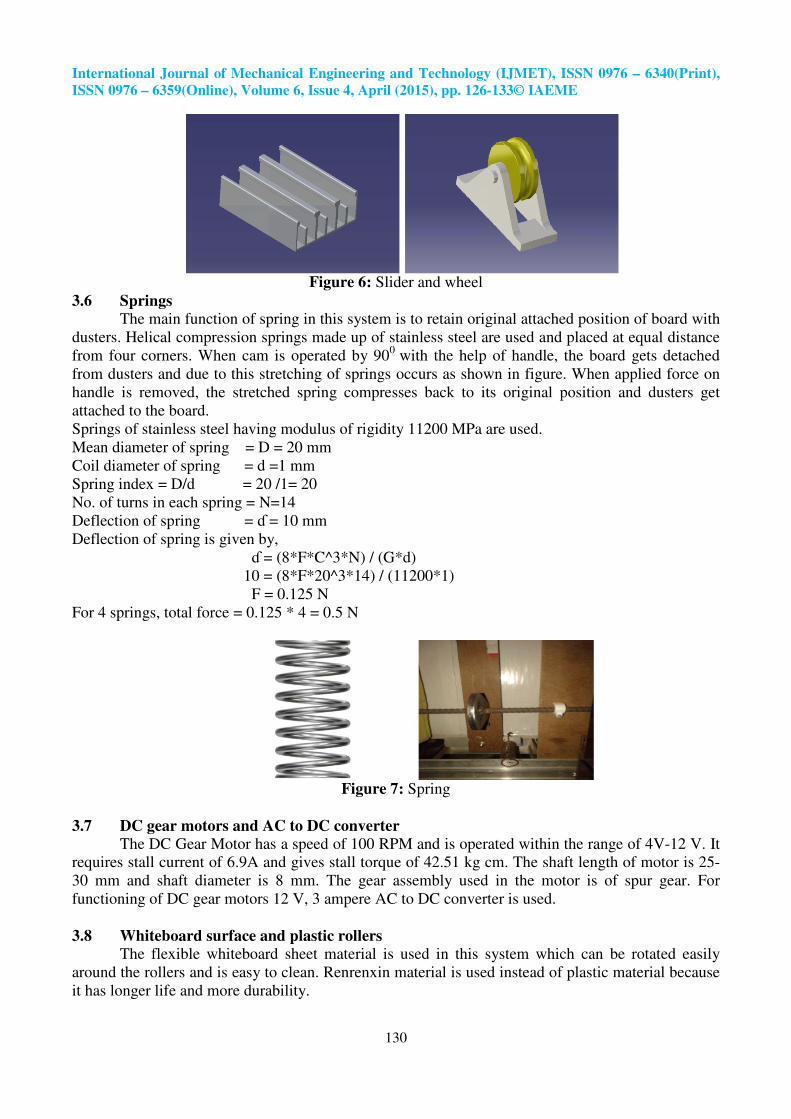
3.5 Slider and wheels
The function of sliders and wheels is to provide smooth longitudinal forward and reverse
movement of wooden block with respect to duster holders for attaching and detaching operation.
Aluminum sliders and high density plastic wheels are used in this system so that they will easily
carry weight of the main base and provide very less amount of friction due to its semicircular mating
interfaces.
International Journal of Mechanical Engineering and Technology (IJMET), ISSN 0976 – 6340(Print),
ISSN 0976 – 6359(Online), Volume 6, Issue 4, April (2015), pp. 126-133© IAEME
130
Figure 6: Slider and wheel
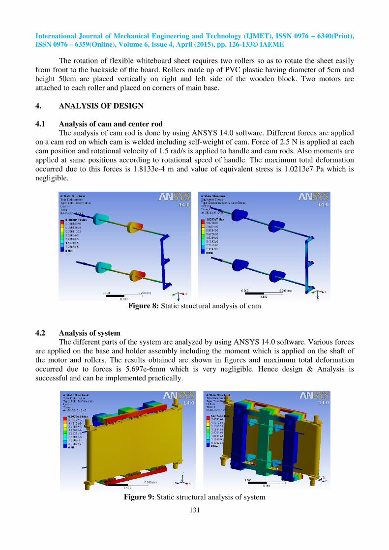
3.6 Springs
The main function of spring in this system is to retain original attached position of board with
dusters. Helical compression springs made up of stainless steel are used and placed at equal distance
from four corners. When cam is operated by 900
with the help of handle, the board gets detached
from dusters and due to this stretching of springs occurs as shown in figure. When applied force on
handle is removed, the stretched spring compresses back to its original position and dusters get
attached to the board.
Springs of stainless steel having modulus of rigidity 11200 MPa are used.
Mean diameter of spring = D = 20 mm
Coil diameter of spring = d =1 mm
Spring index = D/d = 20 /1= 20
No. of turns in each spring = N=14
Deflection of spring = ɗ = 10 mm
Deflection of spring is given by,
ɗ = (8*F*C^3*N) / (G*d)
10 = (8*F*20^3*14) / (11200*1)
F = 0.125 N
For 4 springs, total force = 0.125 * 4 = 0.5 N
Figure 7: Spring
3.7 DC gear motors and AC to DC converter
The DC Gear Motor has a speed of 100 RPM and is operated within the range of 4V-12 V. It
requires stall current of 6.9A and gives stall torque of 42.51 kg cm. The shaft length of motor is 25-
30 mm and shaft diameter is 8 mm. The gear assembly used in the motor is of spur gear. For
functioning of DC gear motors 12 V, 3 ampere AC to DC converter is used.
3.8 Whiteboard surface and plastic rollers
The flexible whiteboard sheet material is used in this system which can be rotated easily
around the rollers and is easy to clean. Renrenxin material is used instead of plastic material because
it has longer life and more durability.
International Journal of Mechanical Engineering and Technology (IJMET), ISSN 0976 – 6340(Print),
ISSN 0976 – 6359(Online), Volume 6, Issue 4, April (2015), pp. 126-133© IAEME
131
The rotation of flexible whiteboard sheet requires two rollers so as to rotate the sheet easily
from front to the backside of the board. Rollers made up of PVC plastic having diameter of 5cm and
height 50cm are placed vertically on right and left side of the wooden block. Two motors are
attached to each roller and placed on corners of main base.
4. ANALYSIS OF DESIGN
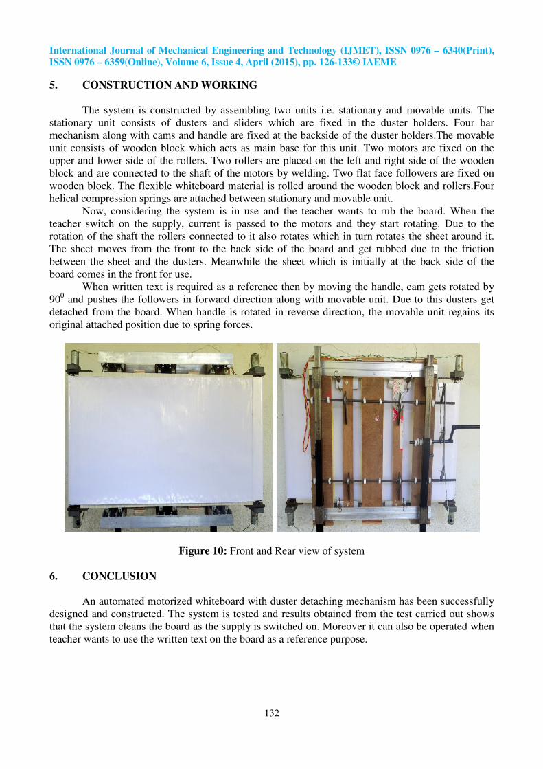
4.1 Analysis of cam and center rod
The analysis of cam rod is done by using ANSYS 14.0 software. Different forces are applied
on a cam rod on which cam is welded including self-weight of cam. Force of 2.5 N is applied at each
cam position and rotational velocity of 1.5 rad/s is applied to handle and cam rods. Also moments are
applied at same positions according to rotational speed of handle. The maximum total deformation
occurred due to this forces is 1.8133e-4 m and value of equivalent stress is 1.0213e7 Pa which is
negligible.
Figure 8: Static structural analysis of cam
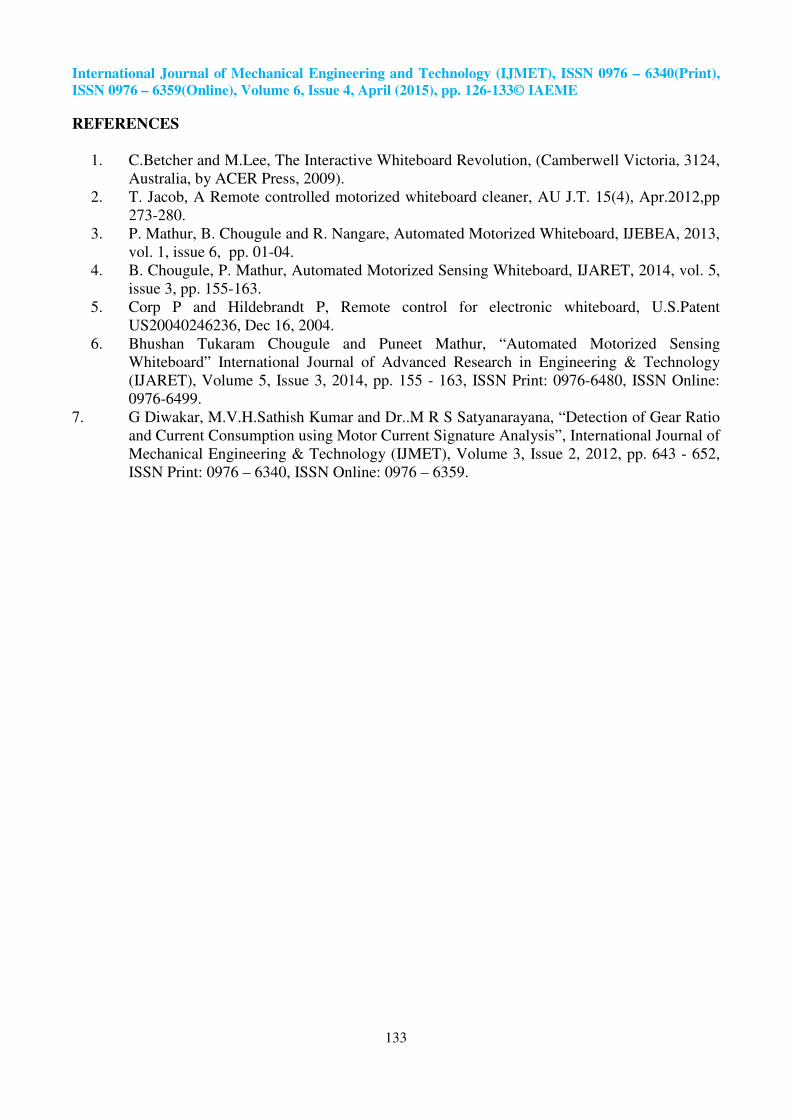
4.2 Analysis of system The different parts of the system are analyzed by using ANSYS 14.0 software. Various forces
are applied on the base and holder assembly including the moment which is applied on the shaft of
the motor and rollers. The results obtained are shown in figures and maximum total deformation
occurred due to forces is 5.697e-6mm which is very negligible. Hence design & Analysis is
successful and can be implemented practically.
Figure 9: Static structural analysis of system
International Journal of Mechanical Engineering and Technology (IJMET), ISSN 0976 – 6340(Print),
ISSN 0976 – 6359(Online), Volume 6, Issue 4, April (2015), pp. 126-133© IAEME
132
5. CONSTRUCTION AND WORKING
The system is constructed by assembling two units i.e. stationary and movable units. The
stationary unit consists of dusters and sliders which are fixed in the duster holders. Four bar
mechanism along with cams and handle are fixed at the backside of the duster holders.The movable
unit consists of wooden block which acts as main base for this unit. Two motors are fixed on the
upper and lower side of the rollers. Two rollers are placed on the left and right side of the wooden
block and are connected to the shaft of the motors by welding. Two flat face followers are fixed on
wooden block. The flexible whiteboard material is rolled around the wooden block and rollers.Four
helical compression springs are attached between stationary and movable unit.
Now, considering the system is in use and the teacher wants to rub the board. When the
teacher switch on the supply, current is passed to the motors and they start rotating. Due to the
rotation of the shaft the rollers connected to it also rotates which in turn rotates the sheet around it.
The sheet moves from the front to the back side of the board and get rubbed due to the friction
between the sheet and the dusters. Meanwhile the sheet which is initially at the back side of the
board comes in the front for use.
When written text is required as a reference then by moving the handle, cam gets rotated by
900 and pushes the followers in forward direction along with movable unit. Due to this dusters get
detached from the board. When handle is rotated in reverse direction, the movable unit regains its
original attached position due to spring forces.
Figure 10: Front and Rear view of system
6. CONCLUSION
An automated motorized whiteboard with duster detaching mechanism has been successfully
designed and constructed. The system is tested and results obtained from the test carried out shows
that the system cleans the board as the supply is switched on. Moreover it can also be operated when
teacher wants to use the written text on the board as a reference purpose.
International Journal of Mechanical Engineering and Technology (IJMET), ISSN 0976 – 6340(Print),
ISSN 0976 – 6359(Online), Volume 6, Issue 4, April (2015), pp. 126-133© IAEME
133
REFERENCES
1. C.Betcher and M.Lee, The Interactive Whiteboard Revolution, (Camberwell Victoria, 3124,
Australia, by ACER Press, 2009).
2. T. Jacob, A Remote controlled motorized whiteboard cleaner, AU J.T. 15(4), Apr.2012,pp
273-280.
3. P. Mathur, B. Chougule and R. Nangare, Automated Motorized Whiteboard, IJEBEA, 2013,
vol. 1, issue 6, pp. 01-04.
4. B. Chougule, P. Mathur, Automated Motorized Sensing Whiteboard, IJARET, 2014, vol. 5,
issue 3, pp. 155-163.
5. Corp P and Hildebrandt P, Remote control for electronic whiteboard, U.S.Patent
US20040246236, Dec 16, 2004.
6. Bhushan Tukaram Chougule and Puneet Mathur, “Automated Motorized Sensing
Whiteboard” International Journal of Advanced Research in Engineering & Technology
(IJARET), Volume 5, Issue 3, 2014, pp. 155 - 163, ISSN Print: 0976-6480, ISSN Online:
0976-6499.
7. G Diwakar, M.V.H.Sathish Kumar and Dr..M R S Satyanarayana, “Detection of Gear Ratio
and Current Consumption using Motor Current Signature Analysis”, International Journal of
Mechanical Engineering & Technology (IJMET), Volume 3, Issue 2, 2012, pp. 643 - 652,
ISSN Print: 0976 – 6340, ISSN Online: 0976 – 6359.