Hobby-Lobby.com is pleased to announce the 1/4 scale Piper PA-12 “Super Cruiser” as part of its Pilot-1 Golden Age Civilian Series. The Pilot-1 “Super Cruiser” encompasses the same attributes in quality construction and handling that made the original a great design. We know you will be pleased with your new model. Its’ beautiful looks, balanced maneuverability, and docile flying characteristics make it a design that is truly at home cruising the skies at a Pilot-1 Aerodrome near you!
“The end of World War II saw the resumption of private aircraft manufacture and the Piper Aircraft Company, already well known for the J-3 Cub and the J-5 Cruiser, began production of improved models of these aircraft. These were the Piper PA-11 Cub Special and the Piper PA-12 Super Cruiser. Walter Jamoneau, who was head of the engineering department at Piper for many years, modified the J-5 into the PA-12. Test flights were made in December 1945, and the first production version of the aircraft appeared in February 1946.” “The original J-5 series were fabric-covered, three-place, high-wing monoplanes, initially powered by 75-hp Lycoming engines, and later by 90-hp Lycomings. The PA-12 was also fabric-covered, over a welded metal tubular frame and wooden wing spars, and featured a Lycoming O-235-C engine, fully cowled. Later models of the PA-12 had as optional equipment a slightly more powerful engine. Standard features on the PA-12 included an electric starter, navigation lights, and a cabin heater. The Piper PA-12 Super Cruiser was used in a number of roles, from private pleasure flying to light cargo carrying and many are still flying. It was also successful in the export market.” Manufacturer: Piper Aircraft Corp.
Date: 1946 Country of Origin: United States of America
Dimensions: Wingspan: 10.8 m (35 ft 5 in) Length: 6.86 m (22 ft 6 in) Height: 2.08 m (6 ft 10 in) Weight, empty: 454 kg (1,000 lb) Weight, gross: 793 kg (1,750 lb) Top Speed: 184 km/h (115 mph) Engine: Lycoming O-235-C, 100 hp Materials: Fuselage: steel tube with fabric cover Physical Description: Single engine, two seat, high wing, monoplane, [cream] and red, first light aircraft to fly around the world
(Source: Online, NASM, http://www.nasm.si.edu/ , Jan 3, 2009) Search “Piper Super Cruiser” at the following link: http://www.nasm.si.edu/
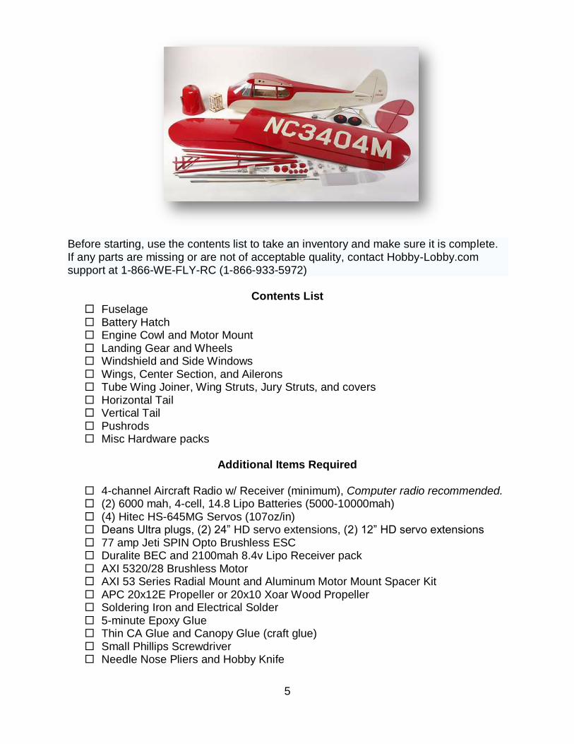
Before starting, use the contents list to take an inventory and make sure it is complete. If any parts are missing or are not of acceptable quality, contact Hobby-Lobby.com support at 1-866-WE-FLY-RC (1-866-933-5972)
Contents List Fuselage Battery Hatch Engine Cowl and Motor Mount Landing Gear and Wheels Windshield and Side Windows Wings, Center Section, and Ailerons Tube Wing Joiner, Wing Struts, Jury Struts, and covers Horizontal Tail Vertical Tail Pushrods Misc Hardware packs
Additional Items Required
4-channel Aircraft Radio w/ Receiver (minimum), Computer radio recommended. (2) 6000 mah, 4-cell, 14.8 Lipo Batteries (5000-10000mah) (4) Hitec HS-645MG Servos (107oz/in) Deans Ultra plugs, (2) 24” HD servo extensions, (2) 12” HD servo extensions 77 amp Jeti SPIN Opto Brushless ESC Duralite BEC and 2100mah 8.4v Lipo Receiver pack AXI 5320/28 Brushless Motor AXI 53 Series Radial Mount and Aluminum Motor Mount Spacer Kit APC 20x12E Propeller or 20x10 Xoar Wood Propeller Soldering Iron and Electrical Solder 5-minute Epoxy Glue Thin CA Glue and Canopy Glue (craft glue) Small Phillips Screwdriver Needle Nose Pliers and Hobby Knife
6
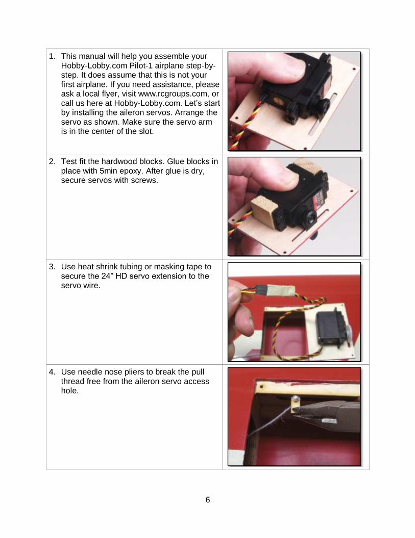
1. This manual will help you assemble your Hobby-Lobby.com Pilot-1 airplane step-by-step. It does assume that this is not your first airplane. If you need assistance, please ask a local flyer, visit www.rcgroups.com, or call us here at Hobby-Lobby.com. Let’s start by installing the aileron servos. Arrange the servo as shown. Make sure the servo arm is in the center of the slot.
2. Test fit the hardwood blocks. Glue blocks in place with 5min epoxy. After glue is dry, secure servos with screws.
3. Use heat shrink tubing or masking tape to secure the 24” HD servo extension to the servo wire.
4. Use needle nose pliers to break the pull
thread free from the aileron servo access hole.
7
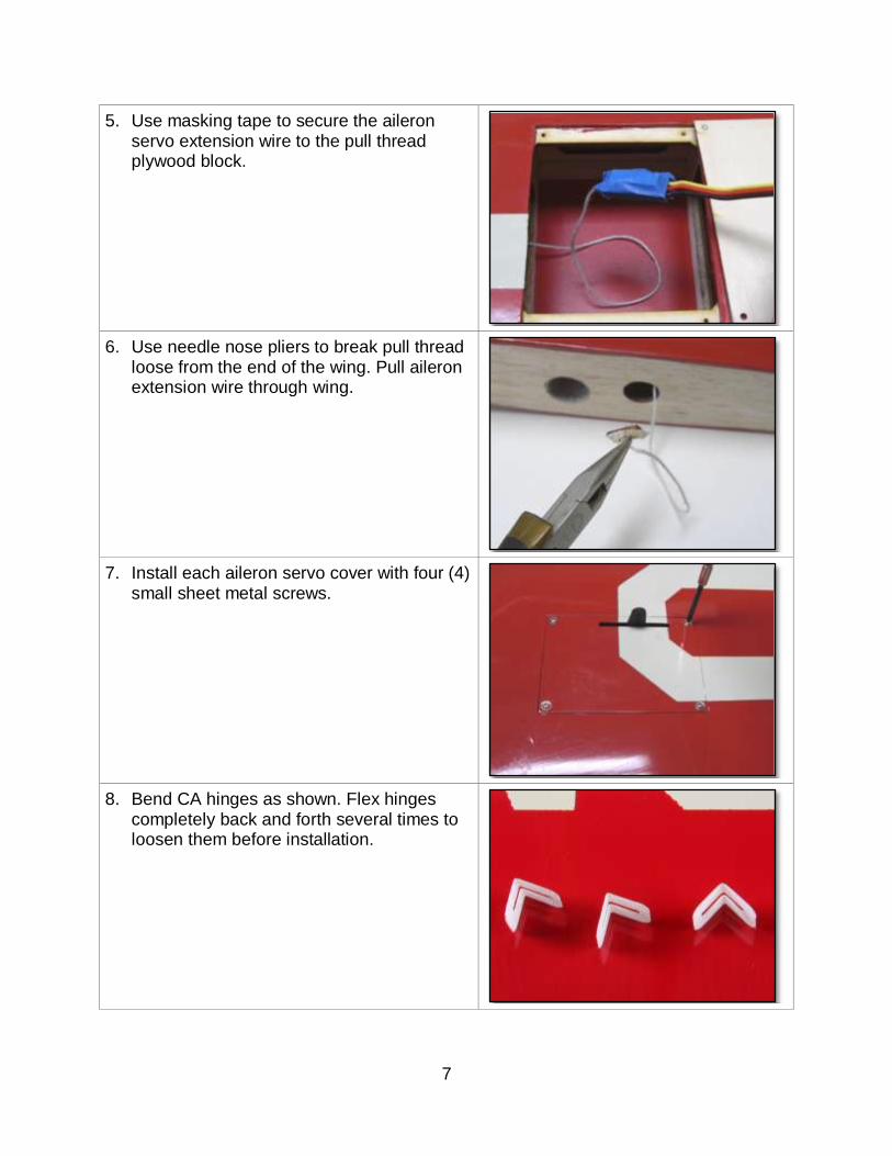
5. Use masking tape to secure the aileron servo extension wire to the pull thread plywood block.
6. Use needle nose pliers to break pull thread loose from the end of the wing. Pull aileron extension wire through wing.
7. Install each aileron servo cover with four (4) small sheet metal screws.
8. Bend CA hinges as shown. Flex hinges completely back and forth several times to loosen them before installation.
8
9. Insert CA hinges and aileron into wing. Make sure alignment is good with even spaces at each end of aileron.
10. With aileron deflected downward and fitted with no gap between the leading edge of aileron and wing, CA each hinge. Use thin CA, 2-3 drops per hinge, per side.
11. Locate the aileron horns and pushrod parts as shown.
12. Use straight edge and pen to mark where the aileron control horn will be attached.
9
13. Using the line drawn in the step above, measure 6mm (1/4”) from the beveled leading edge of the aileron and mark with pen.
14. Use a 3mm (1/8”) drill bit to drill hole completely through aileron. Be careful to keep drill straight and true.
15. Insert long aileron horn screw through washer and aileron from the top surface. Insert washer, nut, and nylon horn on bottom surface as shown. Use threadlocker on nut and secure nut (do not over tighten). You may wish to also lightly bend screw toward servo arm as shown.
16. Assemble aileron pushrod. Insert clevis into outer hole of servo arm as shown. Don’t forget to use blue thread lock on at least one end of the pushrod and to use the fuel tubing safety on the clevis.
10
17. Adjust clevis to correct length and connect to aileron horn. Slide fuel tubing safety onto clevis to prevent accidental disconnect. Tighten locknut.
18. Now prepare the Elevator pushrod system for installation. Here are the parts you will need for the next few steps.
19. Start by inserting the elevator pushrod, aluminum end first, into the fuselage. In this picture, the elevator is the top slot. The rudder cable exit is the short exit underneath. And the elevator pushrod screw access hole is on the bottom. Note: scrap covering is supplied to cover this hole after installation.
20. Insert the aluminum crossover arm thru the slots in the fuselage and into the slot in the end of the pushrod. Use threadlocker on the hex head screw and insert into hole in the pushrod end as shown. You may find it easier to temporarily tape (or lightly CA) the screw head to the hex driver while getting the screw started.
11
21. Temporarily install the vertical stabilizer. Do not glue anything in the next several steps. Insert horizontal stabilizer into slot. Measure each side of the horizontal stabilizer to make sure it is centered. You can also see the structure through the covering to help you align.
22. Then align the horizontal stabilizer with a 90 degree triangle as shown. One side of the triangle is touching the vertical stabilizer and the other side is for aligning the horizontal stabilizer.
23. Use a permanent pen to mark top and bottom of the horizontal stabilizer as shown. This mark can be removed later with rubbing alcohol and a paper towel.
24. Remove the covering about 1/8” inside the marks made in the previous step. Use a solder iron to melt a line in the covering while gently pulling up on the triangle to be removed. Again, be very careful not to damage the wood. Do not use a knife of any kind as it could damage the wood underneath and cause structural failure of the tail.
12
25. Use rubbing alcohol and a paper towel to remove the marks. Insert the horizontal into the slot. Repeat the measurements in steps 21 & 22.
26. Use thin CA to glue horizontal stabilizer to the fuselage. Make sure to glue all four (4) joints thoroughly. *Do not use accelerator as it tends to fog the covering.
27. Use the same technique used with the aileron CA hinges to install the elevator CA hinges. There should be very little or no gap. Deflect elevator downward and use 2-3 drops of thin CA, per hinge, per side.
28. Place the fuselage upside down. Install the elevator control horns and pushrods as shown. Use thread lock glue on at least one end of each short pushrod. Adjust the length of each short pushrod so that the “T” is in the center of the slot and the elevators are level. Tighten the locknuts and slide the fuel tubing scraps over the clevises as shown.
13
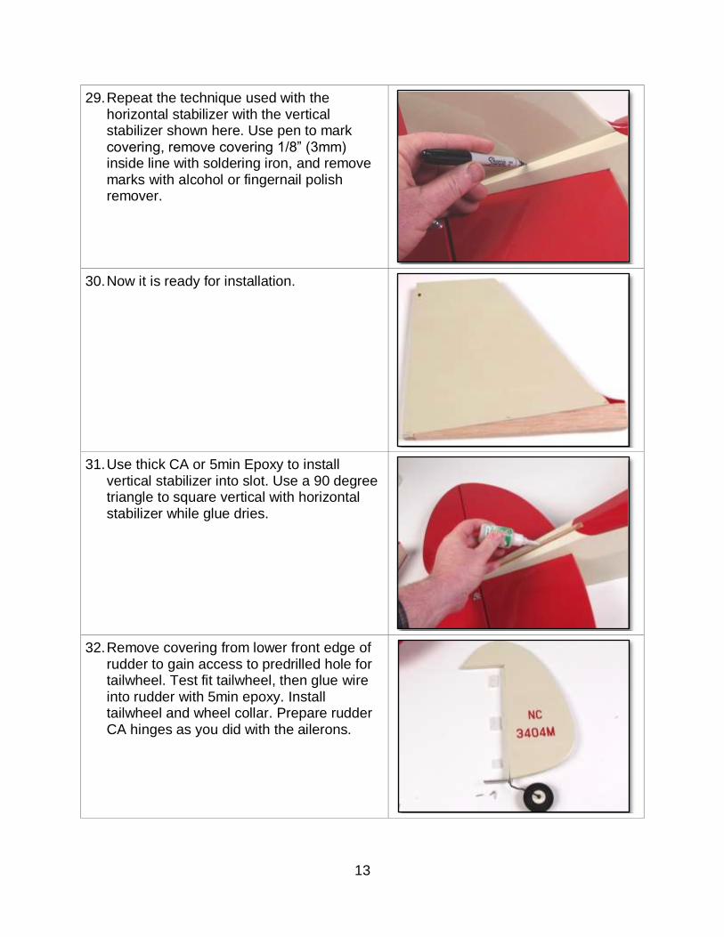
29. Repeat the technique used with the horizontal stabilizer with the vertical stabilizer shown here. Use pen to mark covering, remove covering 1/8” (3mm) inside line with soldering iron, and remove marks with alcohol or fingernail polish remover.
30. Now it is ready for installation.
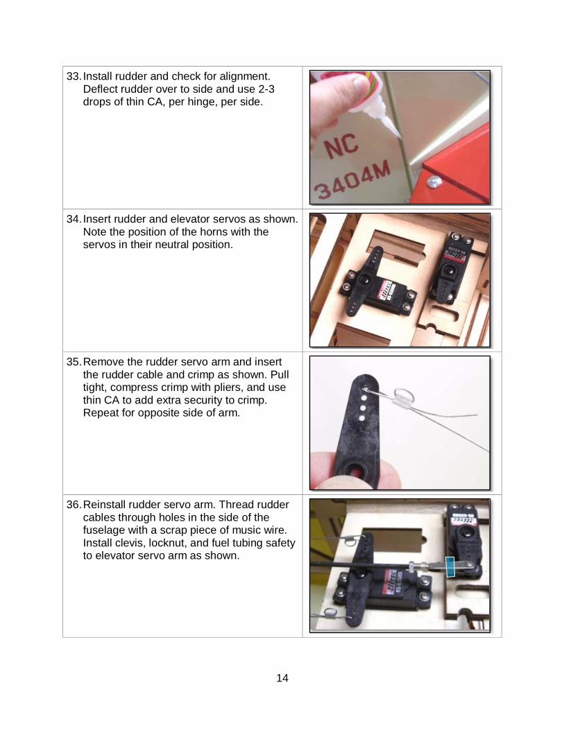
31. Use thick CA or 5min Epoxy to install vertical stabilizer into slot. Use a 90 degree triangle to square vertical with horizontal stabilizer while glue dries.
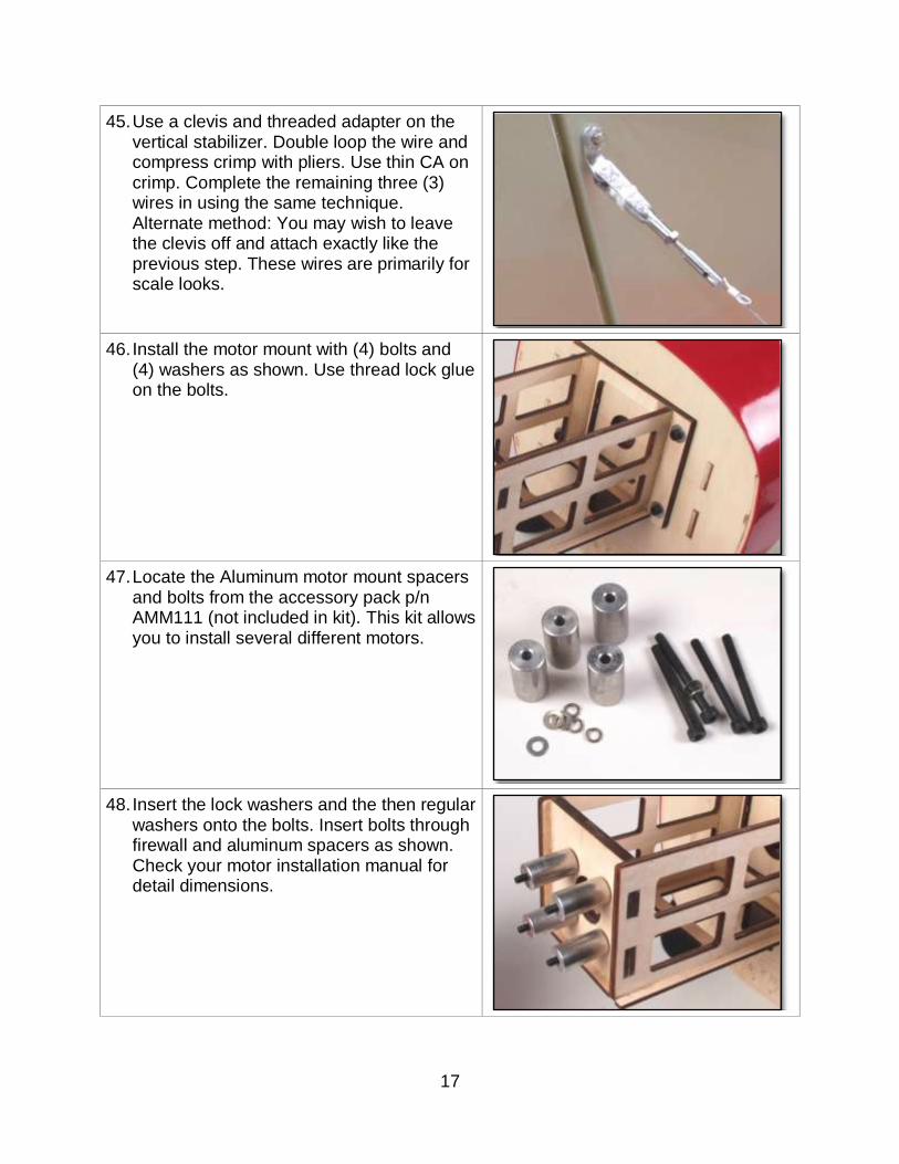
32. Remove covering from lower front edge of rudder to gain access to predrilled hole for tailwheel. Test fit tailwheel, then glue wire into rudder with 5min epoxy. Install tailwheel and wheel collar. Prepare rudder CA hinges as you did with the ailerons.
14
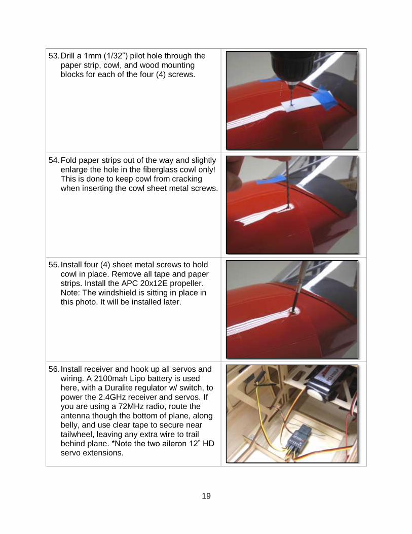
33. Install rudder and check for alignment. Deflect rudder over to side and use 2-3 drops of thin CA, per hinge, per side.
34. Insert rudder and elevator servos as shown. Note the position of the horns with the servos in their neutral position.
35. Remove the rudder servo arm and insert the rudder cable and crimp as shown. Pull tight, compress crimp with pliers, and use thin CA to add extra security to crimp. Repeat for opposite side of arm.
36. Reinstall rudder servo arm. Thread rudder cables through holes in the side of the fuselage with a scrap piece of music wire. Install clevis, locknut, and fuel tubing safety to elevator servo arm as shown.
15
37. Pull rudder cable straight. Mark where rudder horn will go with pen.
38. Drill hole through rudder. Insert rudder control horn as shown. The opposite side is identical. Use blue thread lock to secure horn in place.
39. Attach clevis, fuel tubing safety, lock nut, and treaded coupler to rudder control horn. Make sure rudder servo is centered and rudder cannot move. Loop rudder cable as shown, compress crimp with pliers, and use thin CA to secure. Repeat for opposite side. Note: when tensioning rudder cables, they should have no slop, but they should still be loose.
40. Locate all the parts necessary for the landing gear installation.
16
41. Install four (4) aluminum straps and eight (8) sheet metal screws on each corner of landing gear wire as shown.
42. Install wheels, wheel collars, and hubcaps. We used UHUpor contact cement to glue hubcaps in place. You could also use canopy glue.
43. Locate the parts needed to create the tail brace wires.
44. Use needle nose pliers to bend each of the aluminum brackets to the shape shown in this photo. Attach the braided cable to the horizontal stabilizer with a crimp. Loop the wire through the crimp twice then compress the crimp with pliers. Use thin CA on each crimp for extra security. NOTE: see optional solid flying wire system at the end of this manual (not included).
17
45. Use a clevis and threaded adapter on the vertical stabilizer. Double loop the wire and compress crimp with pliers. Use thin CA on crimp. Complete the remaining three (3) wires in using the same technique. Alternate method: You may wish to leave the clevis off and attach exactly like the previous step. These wires are primarily for scale looks.
46. Install the motor mount with (4) bolts and (4) washers as shown. Use thread lock glue on the bolts.
47. Locate the Aluminum motor mount spacers and bolts from the accessory pack p/n AMM111 (not included in kit). This kit allows you to install several different motors.
48. Insert the lock washers and the then regular washers onto the bolts. Insert bolts through firewall and aluminum spacers as shown. Check your motor installation manual for detail dimensions.
18
49. Install motor.
50. Attach the ESC to the motor box with sheet metal screws. Route wires as necessary to receiver and battery. It is necessary to reverse two of the motor wires in this application. Black-Yellow, Red-Red- Yellow-Black.
51. Install the four (4) cowling blocks with 5min epoxy evenly spaced as shown. Cut four (4) strips of paper approx. 1/2” wide and 3” long. Use tape to install paper strips over each cowling block. Mark the center of the block. NOTE: Do not mount blocks on side of fuselage because cowl does not touch the sides. Mount at corners as shown.
52. Align cowl with propeller shaft face 5mm
(3/16”) in front of cowl. Use masking tape to hold cowl in position for next few steps.
19
53. Drill a 1mm (1/32”) pilot hole through the paper strip, cowl, and wood mounting blocks for each of the four (4) screws.
54. Fold paper strips out of the way and slightly enlarge the hole in the fiberglass cowl only! This is done to keep cowl from cracking when inserting the cowl sheet metal screws.
55. Install four (4) sheet metal screws to hold cowl in place. Remove all tape and paper strips. Install the APC 20x12E propeller. Note: The windshield is sitting in place in this photo. It will be installed later.
56. Install receiver and hook up all servos and wiring. A 2100mah Lipo battery is used here, with a Duralite regulator w/ switch, to power the 2.4GHz receiver and servos. If you are using a 72MHz radio, route the antenna though the bottom of plane, along belly, and use clear tape to secure near tailwheel, leaving any extra wire to trail behind plane. *Note the two aileron 12” HD servo extensions.
20
57. This is looking in through the battery hatch (airplane is upside down). Install the Duralite Receiver regulator with switch. The Deans Ultra connector for the receiver LiPo is shown on the right side of the photo.
58. Install Velcro strips and straps for holding the two “6000-4S” batteries. When you determine the CG for your airplane, make a mark on the battery tray so that you put the batteries in the same place every time.
59. Install the Deans Ultra “Series Module” as shown. Glue module in place, behind the firewall, using PFM glue or 5min Epoxy.
60. Use canopy glue to install all four (4) side
windows. Use a wet paper towel to clean up any mess before glue dries. Apply masking tape to hold everything in place while the glue dries.
21
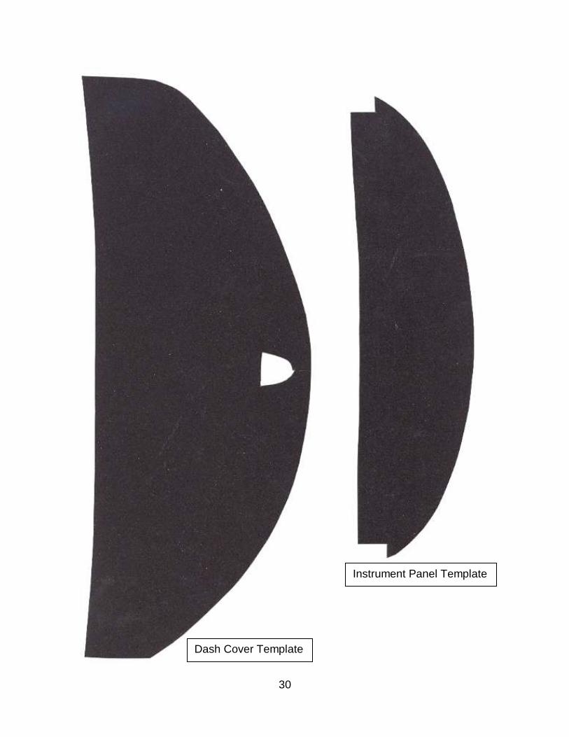
61. You may wish to install a black dash and instrument panel. Use the templates at the back of this manual to fabricate them. We used dark grey 600-grit wet/dry sandpaper for our prototype. Trial fit the windshield to make sure dash doesn’t show around edges. Use contact cement or spray adhesive to install.
62. Install windshield with canopy glue. Use a wet paper towel to clean up any mess before glue dries. Apply masking tape to hold everything in place while the glue dries overnight. We used hobby enamel paint to trim the edges of the windshield. You may wish to do so as well.
63. Use a 5/64” (2mm) drill bit or smaller for the next few steps. Wrap the shaft of the drill bit with 1 to 2 layers of masking tape (or heat shrink tubing). This will allow the drill bit to cut through only one side of the wing tube but also protect the preinstalled blind nut threads in the wing.
64. Insert both aluminum joiner tubes fully into one wing panel. Drill through one side of the wing tubes. This is only 1/16” (1mm). NOTE: Do not drill all the way though the wing.
22
65. Pull the wing tubes out until you can see the holes drilled in the previous step. Use a 3/32” (2.5mm) drill bit to enlarge the holes in both wing tube joiners.
66. Insert both aluminum joiner tubes fully into the wing panel. Rotate wing tube joiner until drilled holes align with internal blind nuts. Insert 3mm Phillips or hex-head machine screws. Tighten so that they thread into wing tubes. NOTE: Mark the ends of each spar tube with a “Left Wing” and “Right Wing” so that holes will align during field assembly.
67. With the wing tube screws installed in the first wing panel, slide the center section and opposite wing onto the wing joiner tubes. Use the masking tape covering bit to drill both wing tubes on the new wing panel.
68. Slide the wing panel out, enlarge hole with larger drill bit, slide wing panel back in place, and insert screws into wing joiner tube. Now you can unbolt the wing sections. Again, make sure to mark the tube for “left wing” and “right wing.”
23
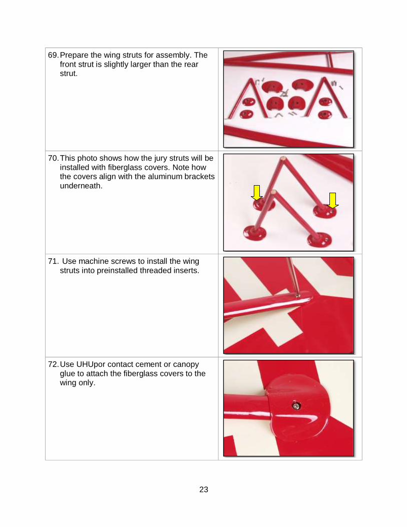
69. Prepare the wing struts for assembly. The front strut is slightly larger than the rear strut.
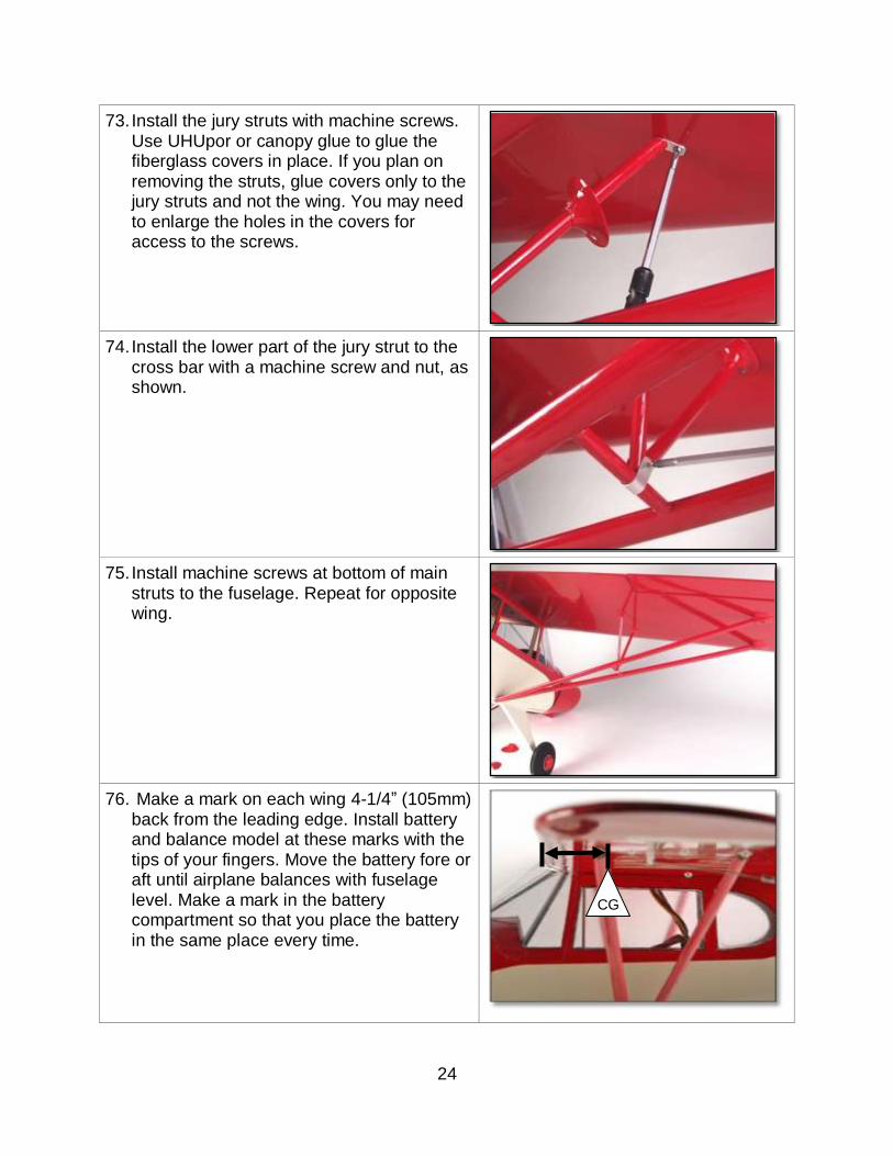
70. This photo shows how the jury struts will be installed with fiberglass covers. Note how the covers align with the aluminum brackets underneath.
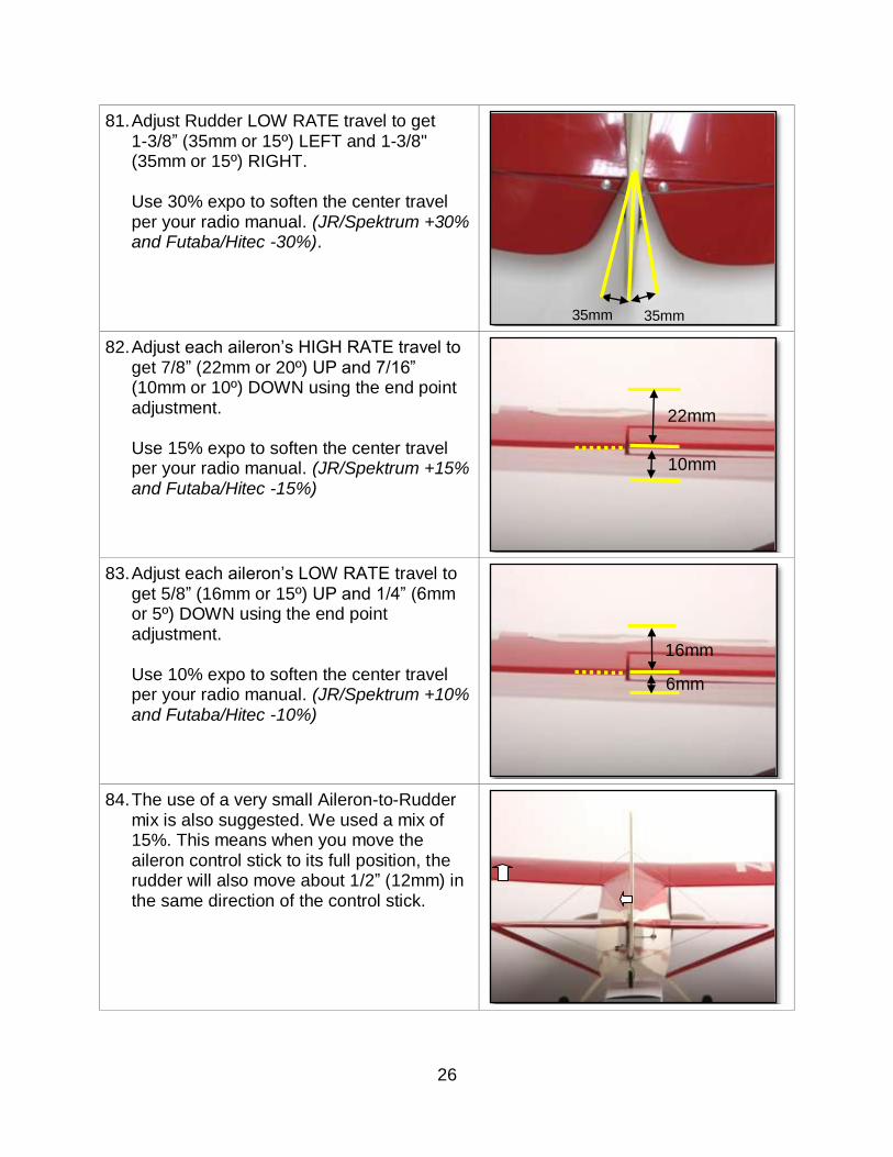
71. Use machine screws to install the wing struts into preinstalled threaded inserts.
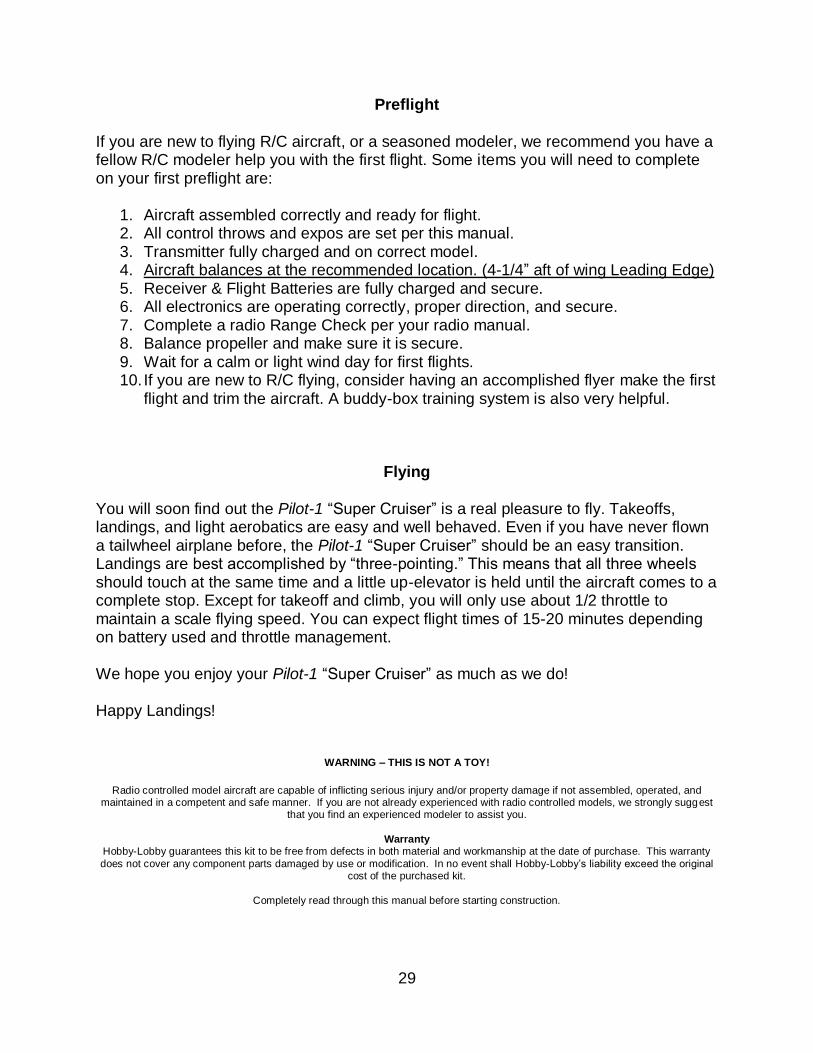
72. Use UHUpor contact cement or canopy glue to attach the fiberglass covers to the wing only.
24
73. Install the jury struts with machine screws. Use UHUpor or canopy glue to glue the fiberglass covers in place. If you plan on removing the struts, glue covers only to the jury struts and not the wing. You may need to enlarge the holes in the covers for access to the screws.
74. Install the lower part of the jury strut to the cross bar with a machine screw and nut, as shown.
75. Install machine screws at bottom of main struts to the fuselage. Repeat for opposite wing.
76. Make a mark on each wing 4-1/4” (105mm) back from the leading edge. Install battery and balance model at these marks with the tips of your fingers. Move the battery fore or aft until airplane balances with fuselage level. Make a mark in the battery compartment so that you place the battery in the same place every time.
CG
25
77. Please refer to your radio manual for the following few steps. Please note that some computer radios have separate settings for exponential for high and low rate positions. Make sure you double check all settings before flight. If you are new to programming, check with a local experienced modeler or hobby shop for assistance. The use of Exponential (expo) and Aileron-Rudder mix is recommended.
78. Adjust Elevator HIGH RATE travel to get
1-1/2” (38mm or 20º) up and 1-1/2” (38mm or 20º) down. Use 30% expo to soften the center travel per your radio manual. (JR/Spektrum +30% and Futaba/Hitec -30%)
79. Adjust Elevator LOW RATE travel to get
7/8” (22mm or 10º) up and 7/8” (22mm or 10º) down travel. Use 20% expo to soften the center travel per your radio manual. (JR/Spektrum +20% and Futaba/Hitec -20%)
80. Adjust Rudder HIGH RATE travel to get 1-7/8” (45mm or 20º) left and 1-7/8" (45mm or 20º) right Use 30% expo to soften the center travel per your radio manual. (JR/Spektrum +30% and Futaba/Hitec -30%).
38mm
38mm
22mm
22mm
45mm 45mm
26
81. Adjust Rudder LOW RATE travel to get 1-3/8” (35mm or 15º) LEFT and 1-3/8" (35mm or 15º) RIGHT.
Use 30% expo to soften the center travel per your radio manual. (JR/Spektrum +30% and Futaba/Hitec -30%).
82. Adjust each aileron’s HIGH RATE travel to
get 7/8” (22mm or 20º) UP and 7/16” (10mm or 10º) DOWN using the end point adjustment.
Use 15% expo to soften the center travel per your radio manual. (JR/Spektrum +15% and Futaba/Hitec -15%)
83. Adjust each aileron’s LOW RATE travel to get 5/8” (16mm or 15º) UP and 1/4” (6mm or 5º) DOWN using the end point adjustment. Use 10% expo to soften the center travel per your radio manual. (JR/Spektrum +10% and Futaba/Hitec -10%)
84. The use of a very small Aileron-to-Rudder mix is also suggested. We used a mix of 15%. This means when you move the aileron control stick to its full position, the rudder will also move about 1/2” (12mm) in the same direction of the control stick.
35mm 35mm
22mm
10mm
6mm
16mm
27
85. Alternate Tail Brace instructions. You may wish to create a more scale tail brace system for your PA-12. These parts are not included in the kit but are easy to fabricate. Dubro sells a tail brace kit (Dubro p/n 205) that is very similar to this if you wish to purchase something a little more ready made.
86. Use silver solder to attach unshielded
electrical crimp connector to one end of a 4-40 (2mm) steel pushrod.
87. Temporarily attach the pushrod to the tail with a machine screw and nut as shown.
88. Temporarily install an electrical connector to the opposite end. Cut the 4-40 (2mm) steel rod to length. Be careful to retain tail alignment with wing. Remove steel rod and crimp from airplane and silver solder the end in place. Reattach completed tail brace wire. Repeat for the remaining braces.
28
89. When all braces are complete, install with machine screws, nuts, and blue thread lock glue.
You are now finished! Now go fly and enjoy your new Hobby-Lobby “Pilot-1 Piper PA-12 Cub Super Cruiser”!
29
Preflight If you are new to flying R/C aircraft, or a seasoned modeler, we recommend you have a fellow R/C modeler help you with the first flight. Some items you will need to complete on your first preflight are:
1. Aircraft assembled correctly and ready for flight. 2. All control throws and expos are set per this manual. 3. Transmitter fully charged and on correct model. 4. Aircraft balances at the recommended location. (4-1/4” aft of wing Leading Edge) 5. Receiver & Flight Batteries are fully charged and secure. 6. All electronics are operating correctly, proper direction, and secure. 7. Complete a radio Range Check per your radio manual. 8. Balance propeller and make sure it is secure. 9. Wait for a calm or light wind day for first flights. 10. If you are new to R/C flying, consider having an accomplished flyer make the first
flight and trim the aircraft. A buddy-box training system is also very helpful.
Flying You will soon find out the Pilot-1 “Super Cruiser” is a real pleasure to fly. Takeoffs, landings, and light aerobatics are easy and well behaved. Even if you have never flown a tailwheel airplane before, the Pilot-1 “Super Cruiser” should be an easy transition. Landings are best accomplished by “three-pointing.” This means that all three wheels should touch at the same time and a little up-elevator is held until the aircraft comes to a complete stop. Except for takeoff and climb, you will only use about 1/2 throttle to maintain a scale flying speed. You can expect flight times of 15-20 minutes depending on battery used and throttle management. We hope you enjoy your Pilot-1 “Super Cruiser” as much as we do! Happy Landings!
WARNING – THIS IS NOT A TOY!
Radio controlled model aircraft are capable of inflicting serious injury and/or property damage if not assembled, operated, and maintained in a competent and safe manner. If you are not already experienced with radio controlled models, we strongly suggest
that you find an experienced modeler to assist you.
Warranty
Hobby-Lobby guarantees this kit to be free from defects in both material and workmanship at the date of purchase. This warranty
does not cover any component parts damaged by use or modification. In no event shall Hobby-Lobby’s liability exceed the original cost of the purchased kit.
Completely read through this manual before starting construction.
30
Dash Cover Template
Instrument Panel Template
31
32
2008 Official Academy of Model Aeronautics National Model Aircraft Safety Code
GENERAL
1. A model aircraft shall be defined as a non-human-carrying device capable of sustained flight in the atmosphere. It shall not exceed limitations established in this code and is intended to be used exclusively for recreational or competition activity.
2. The maximum takeoff weight of a model aircraft, including fuel, is 55 pounds, except for those flown under the AMA Experimental Aircraft Rules.
3. I will abide by this Safety Code and all rules established for the flying site I use. I will not willfully fly my model aircraft in a reckless and/or dangerous manner.
4. I will not fly my model aircraft in sanctioned events, air shows, or model demonstrations until it has been proven airworthy.
5. I will not fly my model aircraft higher than approximately 400 feet above ground level, when within three (3) miles of an airport without notifying the airport operator. I will yield the right-of-way and avoid flying in the proximity of full-scale aircraft, utilizing a spotter when appropriate.
6. I will not fly my model aircraft unless it is identified with my name and address, or AMA number, inside or affixed to the outside of the model aircraft. This does not apply to model aircraft flown indoors.
7. I will not operate model aircraft with metal-blade propellers or with gaseous boosts (other than air), nor will I operate model aircraft with fuels containing tetranitromethane or hydrazine.
8. I will not operate model aircraft carrying pyrotechnic devices which explode burn, or propel a projectile of any kind. Exceptions include Free Flight fuses or devices that burn producing smoke and are securely attached to the model aircraft during flight. Rocket motors up to a G-series size may be used, provided they remain firmly attached to the model aircraft during flight. Model rockets may be flown in accordance with the National Model Rocketry Safety Code; however, they may not be launched from model aircraft. Officially designated AMA Air Show Teams (AST) are authorized to use devices and practices as defined within the Air Show Advisory Committee Document.
9. I will not operate my model aircraft while under the influence of alcohol or within eight (8) hours of having consumed alcohol.
10. I will not operate my model aircraft while using any drug which could adversely affect my ability to safely control my model aircraft.
11. Children under six (6) years old are only allowed on a flightline or in a flight area as a pilot or while under flight instruction.
12. When and where required by rule, helmets must be properly worn and fastened. They must be OSHA, DOT, ANSI, SNELL or NOCSAE approved or comply with comparable standards.
RADIO CONTROL
1. All model flying shall be conducted in a manner to avoid over flight of unprotected people. 2. I will have completed a successful radio equipment ground-range check before the first flight of a
new or repaired model aircraft. 3. I will not fly my model aircraft in the presence of spectators until I become a proficient flier, unless
I am assisted by an experienced pilot. 4. At all flying sites a line must be established, in front of which all flying takes place. Only personnel
associated with flying the model aircraft are allowed at or in front of the line. In the case of airshows demonstrations straight line must be established. An area away from the line must be maintained for spectators. Intentional flying behind the line is prohibited.
5. I will operate my model aircraft using only radio-control frequencies currently allowed by the Federal Communications Commission (FCC). Only individuals properly licensed by the FCC are authorized to operate equipment on Amateur Band frequencies.
6. I will not knowingly operate my model aircraft within three (3) miles of any preexisting flying site without a frequency-management agreement. A frequency management agreement may be an
(continued)
33
allocation of frequencies for each site, a day-use agreement between sites, or testing which determines that no interference exists. A frequency-management agreement may exist between two or more AMA chartered clubs, AMA clubs and individual AMA members, or individual AMA members. Frequency-management agreements, including an interference test report if the agreement indicates no interference exists, will be signed by all parties and copies provided to AMA Headquarters.
7. With the exception of events flown under official AMA rules, no powered model may be flown outdoors closer than 25 feet to any individual, except for the pilot and located at the flightline.
8. Under no circumstances may a pilot or other person touch a model aircraft in flight while it is still under power, except to divert it from striking an individual.
9. Radio-controlled night flying is limited to low-performance model aircraft (less than 100 mph). The model aircraft must be equipped with a lighting system which clearly defines the aircraft's attitude and direction at all times.
10. The operator of a radio-controlled model aircraft shall control it during the entire flight, maintaining visual contact without enhancement other than by corrective lenses that are prescribed for the pilot. No model aircraft shall be equipped with devices which allow it to be flown to a selected location which is beyond the visual range of the pilot.
PARK FLYER SAFE OPERATING RECOMMENDATIONS
Inspect your model before every flight to make certain it is airworthy.
Be aware of any other radio frequency user who may present an interference problem.
Always be courteous and respectful of other users of your selected flight area.
Choose an area clear of obstacles and large enough to safely accommodate your flying activity.
Make certain this area is clear of friends and spectators prior to launching your aircraft.
Be aware of other activities in the vicinity of your flight path that could cause potential conflict.
Carefully plan your flight path prior to launch.
Abide by any and all established AMA National Model Aircraft Safety Code.
34
Hobby Lobby International, Inc. 5614 Franklin Pike Circle