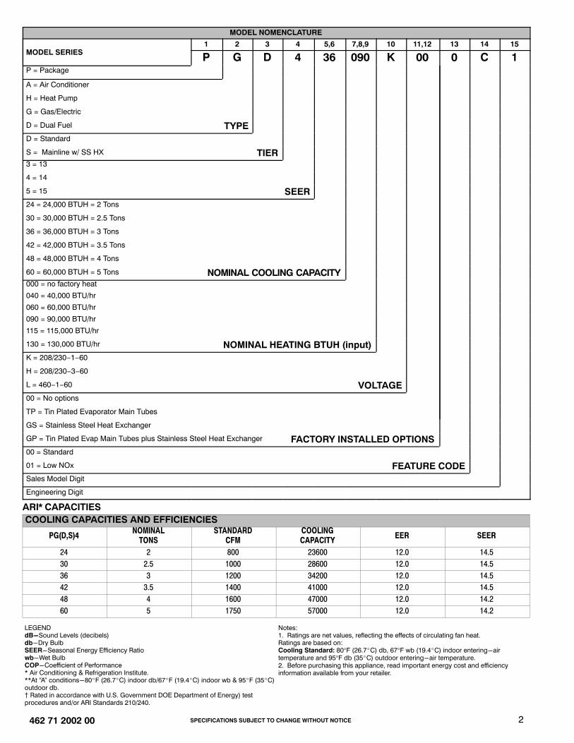
Specifications subject to change without notice. 462 71 2002 00 July 2009 14 SEER, 12 EER, PACKAGE GAS / ELECTRIC UNIT, 2 to 5 TONS Single Phase, 208/230 V, 60 Hz REFRIGERATION CIRCUIT • Environmentally sound R-410A refrigerant • Copper tube/aluminum fin condenser and evaporator coils • Scroll compressor standard on all models EASY TO INSTALL AND SERVICE • Installs easily on a rooftop or at ground level • Easy three-panel accessibility for maintenance and installation • Easily converts to down discharge applications • Combination gas heating and electric cooling BUILT TO LAST • Dense wire grilles (hail guards) standard on all models • Low NOx units available • Induced-draft combustion and venting • Pre-painted steel cabinet • Direct spark ignition • High efficiency X-13 indoor blower motor on all models • Aluminized steel tubular heat exchanger on PGD4 models; Stainless Steel tubular heat exchanger on PGS4 models • Vertical condenser fan discharge • Full perimeter steel base rails • High and low pressure switches provide added reliability for the compressor • All models available with optional factory installed tin-coated copper evaporator coil (These models are identified with letters TP in the 11th and 12th positions in the model number) WARRANTY* • 15 year heat exchanger limited warranty on PGD4; Lifetime heat exchanger limited warranty on PGS4 models. • 5 year parts limited warranty (including compressor and coils) - With timely registration, an additional 5 year parts limited warranty (including compressor and coils) * Applies to original purchaser/homeowner, some limitations may apply. See warranty certificate for complete details. UNIT PERFORMANCE DATA Stainless Steel Heat Exchanger COOLING HEATING Unit Dimensions Height x Width x Depth in (mm) Operating Weight lbs (kg) Aluminized Steel Heat Exchanger Capacity BTU/h SEER EER Input BTU/h Efficiency AFUE % PGD424040K00*C PGS424040KGS*C 23,600 14.5 12.0 40,000 80.0 40 x 48 3 / 16 x 32 5 / 8 (1016 x 1224 x 829) 330 (149) PGD424040KTP*C PGS424040KGP*C 23,600 14.5 12.0 40,000 80.0 40 x 48 3 / 16 x 32 5 / 8 (1016 x 1224 x 829) 330 (149) PGD424060K00*C PGS424060KGS*C 23,600 14.5 12.0 60,000 80.0 40 x 48 3 / 16 x 32 5 / 8 (1016 x 1224 x 829) 330 (149) PGD424060KTP*C PGS424060KGP*C 23,600 14.5 12.0 60,000 80.0 40 x 48 3 / 16 x 32 5 / 8 (1016 x 1224 x 829) 330 (149) PGD430040K00*C PGS430040KGS*C 28,600 14.5 12.0 40,000 80.0 40 x 48 3 / 16 x 32 5 / 8 (1016 x 1224 x 829) 342 (155) PGD430040KTP*C PGS430040KGP*C 28,600 14.5 12.0 40,000 80.0 40 x 48 3 / 16 x 32 5 / 8 (1016 x 1224 x 829) 342 (155) PGD430060K00*C PGS430060KGS*C 28,600 14.5 12.0 60,000 80.0 40 x 48 3 / 16 x 32 5 / 8 (1016 x 1224 x 829) 342 (155) PGD430060KTP*C PGS430060KGP*C 28,600 14.5 12.0 60,000 80.0 40 x 48 3 / 16 x 32 5 / 8 (1016 x 1224 x 829) 342 (155) PGD436060K00*C PGS430060KGP*C 34,200 14.5 12.0 60,000 80.0 46 x 48 3 / 16 x 32 5 / 8 (1167 x 1224 x 829) 376 (170) PGD436060KTP*C PGS436060KGP*C 34,200 14.5 12.0 60,000 80.0 46 x 48 3 / 16 x 32 5 / 8 (1167 x 1224 x 829) 376 (170) PGD436090K00*C PGS436090KGS*C 34,200 14.5 12.0 90,000 79.3 46 x 48 3 / 16 x 32 5 / 8 (1167 x 1224 x 829) 376 (170) PGD436090KTP*C PGS436090KGP*C 34,200 14.5 12.0 90,000 79.3 46 x 48 3 / 16 x 32 5 / 8 (1167 x 1224 x 829) 376 (170) PGD442060K00*C PGS442060KGS*C 41,000 14.5 12.0 60,000 78.5 50 x 48 3 / 16 x 44 1 / 8 (1267 x 1224 x 1123) 463 (210) PGD442060KTP*C PGS442060KGP*C 41,000 14.5 12.0 60,000 78.5 50 x 48 3 / 16 x 44 1 / 8 (1267 x 1224 x 1123) 463 (210) PGD442090K00*C PGS442090KGS*C 41,000 14.5 12.0 90,000 80.4 50 x 48 3 / 16 x 44 1 / 8 (1267 x 1224 x 1123) 463 (210) PGD442090KTP*C PGS442090KGP*C 41,000 14.5 12.0 90,000 80.4 50 x 48 3 / 16 x 44 1 / 8 (1267 x 1224 x 1123) 463 (210) PGD448090K00*C PGS448090KGS*C 47,000 14.2 12.0 90,000 80.4 50 x 48 3 / 16 x 44 1 / 8 (1267 x 1224 x 1123) 481 (218) PGD448090KTP*C PGS448090KGP*C 47,000 14.2 12.0 90,000 80.4 50 x 48 3 / 16 x 44 1 / 8 (1267 x 1224 x 1123) 481 (218) PGD448115K00*C PGS448115KGS*C 47,000 14.2 12.0 115,000 80.3 50 x 48 3 / 16 x 44 1 / 8 (1267 x 1224 x 1123) 481 (218) PGD448115KTP*C PGS448115KGP*C 47,000 14.2 12.0 115,000 80.3 50 x 48 3 / 16 x 44 1 / 8 (1267 x 1224 x 1123) 481 (218) PGD448130K00*C PGS448130KGS*C 47,000 14.2 12.0 130,000 78.9 50 x 48 3 / 16 x 44 1 / 8 (1267 x 1224 x 1123) 481 (218) PGD448130KTP*C PGS448130KGP*C 47,000 14.2 12.0 130,000 78.9 50 x 48 3 / 16 x 44 1 / 8 (1267 x 1224 x 1123) 481 (218) PGD460090K00*C PGS460090KGS*C 57,000 14.2 12.0 90,000 80.4 54 x 48 3 / 16 x 44 1 / 8 (1368 x 1224 x 1123) 509 (231) PGD460090KTP*C PGS460090KGP*C 57,000 14.2 12.0 90,000 80.4 54 x 48 3 / 16 x 44 1 / 8 (1368 x 1224 x 1123) 509 (231) PGD460115K00*C PGS460115KGS*C 57,000 14.2 12.0 115,000 80.3 54 x 48 3 / 16 x 44 1 / 8 (1368 x 1224 x 1123) 509 (231) PGD460115KTP*C PGS460115KGP*C 57,000 14.2 12.0 115,000 80.3 54 x 48 3 / 16 x 44 1 / 8 (1368 x 1224 x 1123) 509 (231) PGD460130K00*C PGS460130KGS*C 57,000 14.2 12.0 130,000 78.9 54 x 48 3 / 16 x 44 1 / 8 (1368 x 1224 x 1123) 509 (231) PGD460130KTP*C PGS460130KGP*C 57,000 14.2 12.0 130,000 78.9 54 x 48 3 / 16 x 44 1 / 8 (1368 x 1224 x 1123) 509 (231) * - 0 = Standard, 1 = Low NOx COMMERCIAL ™ PGD4, PGS4 Product Specifications E N V I R O N M E N T A L L Y S O U N D R E F R I G E R A N T As an Energy Star® Partner, International Comfort Products has determined that this product meets the ENERGY STAR® guidelines for energy efficiency.
Transcript
Specifications subject to change without notice. 462 71 2002 00 July 2009
14 SEER, 12 EER, PACKAGE GAS / ELECTRIC UNIT, 2 to 5 TONSSingle Phase, 208/230 V, 60 HzREFRIGERATION CIRCUIT
• Environmentally sound R-410A refrigerant• Copper tube/aluminum fin condenser and evaporator coils• Scroll compressor standard on all models
EASY TO INSTALL AND SERVICE• Installs easily on a rooftop or at ground level• Easy three-panel accessibility for maintenance and installation• Easily converts to down discharge applications• Combination gas heating and electric cooling
BUILT TO LAST• Dense wire grilles (hail guards) standard on all models• Low NOx units available• Induced-draft combustion and venting• Pre-painted steel cabinet• Direct spark ignition• High efficiency X-13 indoor blower motor on all models• Aluminized steel tubular heat exchanger on PGD4 models;
Stainless Steel tubular heat exchanger on PGS4 models• Vertical condenser fan discharge• Full perimeter steel base rails• High and low pressure switches provide added reliability for the compressor• All models available with optional factory installed tin-coated copper evaporator coil
(These models are identified with letters TP in the 11th and 12th positions in the model number)WARRANTY*
• 15 year heat exchanger limited warranty on PGD4; Lifetime heat exchanger limited warranty on PGS4 models.• 5 year parts limited warranty (including compressor and coils)
- With timely registration, an additional 5 year parts limited warranty (including compressor and coils)*Applies to original purchaser/homeowner, some limitations may apply. See warranty certificate for complete details.
UNIT PERFORMANCE DATA
Stainless Steel HeatExchanger
COOLING HEATING Unit Dimensions Height x Width x Depth
in (mm)
OperatingWeightlbs (kg)
Aluminized SteelHeat Exchanger
Capacity BTU/h SEER EER
InputBTU/h
EfficiencyAFUE %
PGD424040K00*C PGS424040KGS*C 23,600 14.5 12.0 40,000 80.0 40 x 483/16 x 325/8 (1016 x 1224 x 829) 330 (149)PGD424040KTP*C PGS424040KGP*C 23,600 14.5 12.0 40,000 80.0 40 x 483/16 x 325/8 (1016 x 1224 x 829) 330 (149)PGD424060K00*C PGS424060KGS*C 23,600 14.5 12.0 60,000 80.0 40 x 483/16 x 325/8 (1016 x 1224 x 829) 330 (149)PGD424060KTP*C PGS424060KGP*C 23,600 14.5 12.0 60,000 80.0 40 x 483/16 x 325/8 (1016 x 1224 x 829) 330 (149)PGD430040K00*C PGS430040KGS*C 28,600 14.5 12.0 40,000 80.0 40 x 483/16 x 325/8 (1016 x 1224 x 829) 342 (155)PGD430040KTP*C PGS430040KGP*C 28,600 14.5 12.0 40,000 80.0 40 x 483/16 x 325/8 (1016 x 1224 x 829) 342 (155)PGD430060K00*C PGS430060KGS*C 28,600 14.5 12.0 60,000 80.0 40 x 483/16 x 325/8 (1016 x 1224 x 829) 342 (155)PGD430060KTP*C PGS430060KGP*C 28,600 14.5 12.0 60,000 80.0 40 x 483/16 x 325/8 (1016 x 1224 x 829) 342 (155)PGD436060K00*C PGS430060KGP*C 34,200 14.5 12.0 60,000 80.0 46 x 483/16 x 325/8 (1167 x 1224 x 829) 376 (170)PGD436060KTP*C PGS436060KGP*C 34,200 14.5 12.0 60,000 80.0 46 x 483/16 x 325/8 (1167 x 1224 x 829) 376 (170)PGD436090K00*C PGS436090KGS*C 34,200 14.5 12.0 90,000 79.3 46 x 483/16 x 325/8 (1167 x 1224 x 829) 376 (170)PGD436090KTP*C PGS436090KGP*C 34,200 14.5 12.0 90,000 79.3 46 x 483/16 x 325/8 (1167 x 1224 x 829) 376 (170)PGD442060K00*C PGS442060KGS*C 41,000 14.5 12.0 60,000 78.5 50 x 483/16 x 441/8 (1267 x 1224 x 1123) 463 (210)PGD442060KTP*C PGS442060KGP*C 41,000 14.5 12.0 60,000 78.5 50 x 483/16 x 441/8 (1267 x 1224 x 1123) 463 (210)PGD442090K00*C PGS442090KGS*C 41,000 14.5 12.0 90,000 80.4 50 x 483/16 x 441/8 (1267 x 1224 x 1123) 463 (210)PGD442090KTP*C PGS442090KGP*C 41,000 14.5 12.0 90,000 80.4 50 x 483/16 x 441/8 (1267 x 1224 x 1123) 463 (210)PGD448090K00*C PGS448090KGS*C 47,000 14.2 12.0 90,000 80.4 50 x 483/16 x 441/8 (1267 x 1224 x 1123) 481 (218)PGD448090KTP*C PGS448090KGP*C 47,000 14.2 12.0 90,000 80.4 50 x 483/16 x 441/8 (1267 x 1224 x 1123) 481 (218)PGD448115K00*C PGS448115KGS*C 47,000 14.2 12.0 115,000 80.3 50 x 483/16 x 441/8 (1267 x 1224 x 1123) 481 (218)PGD448115KTP*C PGS448115KGP*C 47,000 14.2 12.0 115,000 80.3 50 x 483/16 x 441/8 (1267 x 1224 x 1123) 481 (218)PGD448130K00*C PGS448130KGS*C 47,000 14.2 12.0 130,000 78.9 50 x 483/16 x 441/8 (1267 x 1224 x 1123) 481 (218)PGD448130KTP*C PGS448130KGP*C 47,000 14.2 12.0 130,000 78.9 50 x 483/16 x 441/8 (1267 x 1224 x 1123) 481 (218)PGD460090K00*C PGS460090KGS*C 57,000 14.2 12.0 90,000 80.4 54 x 483/16 x 441/8 (1368 x 1224 x 1123) 509 (231)PGD460090KTP*C PGS460090KGP*C 57,000 14.2 12.0 90,000 80.4 54 x 483/16 x 441/8 (1368 x 1224 x 1123) 509 (231)PGD460115K00*C PGS460115KGS*C 57,000 14.2 12.0 115,000 80.3 54 x 483/16 x 441/8 (1368 x 1224 x 1123) 509 (231)PGD460115KTP*C PGS460115KGP*C 57,000 14.2 12.0 115,000 80.3 54 x 483/16 x 441/8 (1368 x 1224 x 1123) 509 (231)PGD460130K00*C PGS460130KGS*C 57,000 14.2 12.0 130,000 78.9 54 x 483/16 x 441/8 (1368 x 1224 x 1123) 509 (231)PGD460130KTP*C PGS460130KGP*C 57,000 14.2 12.0 130,000 78.9 54 x 483/16 x 441/8 (1368 x 1224 x 1123) 509 (231)
* - 0 = Standard, 1 = Low NOx
COMMERCIAL™ PGD4, PGS4
Product SpecificationsENVIRONM
ENTA
LLY
SO
UN
DR
EFRIGERANT
As an Energy Star® Partner,International Comfort Products hasdetermined that this product meetsthe ENERGY STAR® guidelines forenergy efficiency.
SPECIFICATIONS SUBJECT TO CHANGE WITHOUT NOTICE 2462 71 2002 00
LEGENDdB-Sound Levels (decibels)db-Dry BulbSEER-Seasonal Energy Efficiency Ratiowb-Wet BulbCOP-Coefficient of Performance* Air Conditioning & Refrigeration Institute.**At “A” conditions-80�F (26.7�C) indoor db/67�F (19.4�C) indoor wb & 95�F (35�C)outdoor db.� Rated in accordance with U.S. Government DOE Department of Energy) testprocedures and/or ARI Standards 210/240.
Notes:1. Ratings are net values, reflecting the effects of circulating fan heat.Ratings are based on:Cooling Standard: 80°F (26.7�C) db, 67°F wb (19.4�C) indoor entering-airtemperature and 95°F db (35�C) outdoor entering-air temperature.2. Before purchasing this appliance, read important energy cost and efficiencyinformation available from your retailer.
SPECIFICATIONS SUBJECT TO CHANGE WITHOUT NOTICE3 462 71 2002 00
GAS HEATING CAPACITIES AND EFFICIENCIES
UNIT PG(D,S)4 HEATING INPUT (Btuh) OUTPUT CAPACITY (Btuh) TEMPERATURE RISERANGE °F (°C) AFUE (%)
2404030040 40,000 32,000
30-60(17-33) 80.0
24060300603606042060
60,000
48,00048,00048,00047,000
25-55(14-31)
80.080.080.078.5
36090420904809060090
90,000
72,00073,00073,00073,000
35-65(19-36)
79.380.480.480.4
4811560115 115,000 93,000
30-60(17-33) 80.3
4813060130 130,000 103,000
35-65(19-36) 78.9
LEGENDAFUE-Annual Fuel Utilization EfficiencyNOTE: Before purchasing this appliance, read important energy cost and efficiency information available from your retailer.
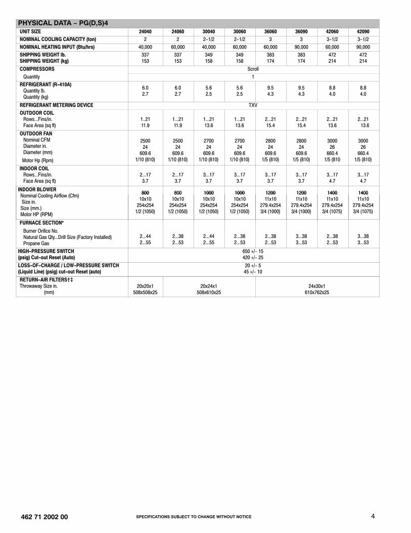
� Required filter sizes shown are based on the larger of the ARI (Air Conditioning and Refrigeration Institute) rated cooling airflow or the heating airflow velocity of300 ft/minute for throwaway type. Air filter pressure drop for non-standard filters must not exceed 0.08 IN. W.C.
� If using accessory filter rack refer to the filter rack installation instructions for correct filter sizes and quantity.
A−WEIGHTED SOUND POWER LEVEL (DBA)MODEL
PGD4, PGS4SOUNDRATING
TYPICAL OCTAVE BAND SPECTRUM (without tone adjustment)125 250 500 1000 2000 4000 8000
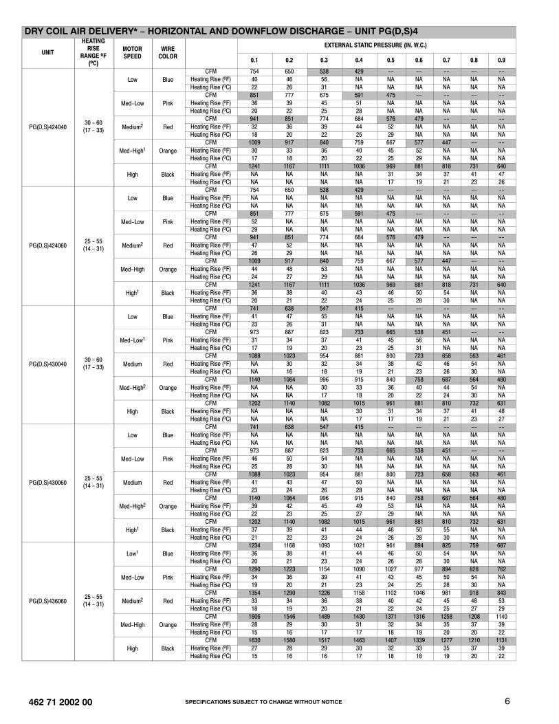
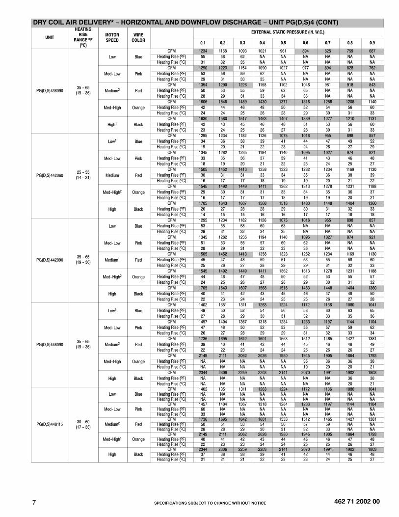
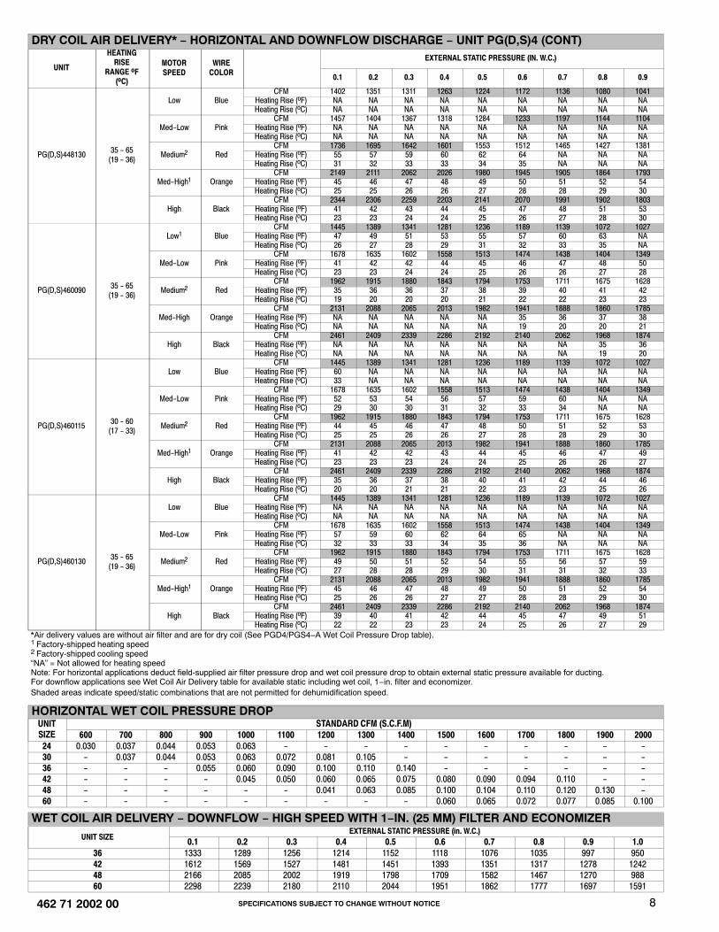
*Air delivery values are without air filter and are for dry coil (See PGD4/PGS4−A Wet Coil Pressure Drop table).1 Factory-shipped heating speed2 Factory-shipped cooling speed“NA” = Not allowed for heating speedNote: For horizontal applications deduct field-supplied air filter pressure drop and wet coil pressure drop to obtain external static pressure available for ducting.For downflow applications see Wet Coil Air Delivery table for available static including wet coil, 1−in. filter and economizer.Shaded areas indicate speed/static combinations that are not permitted for dehumidification speed.
*In the U.S.A., the input rating for altitudes above 2000 ft (610m) must be reduced by 4% for each 1000 ft (305 m) above Sea level.In Canada, the input rating for altitudes from 2001 to 4500 ft (611 to 1372 m) above sea level must be derated by 10% by an authorized gas conversion station or dealer. For Canadian Installations from 2000 to 4500 ft, use U.S.A. column 2001 to 3000 ft.Note: Orifice sizes and manifold pressure settings are based on natural gas with a heating value of 1025 Btu/ft3 amd a specific gravity of .6.† Orifices available through your distributor.
PROPANE GAS ORIFICE SIZES AND MANIFOLD PRESSURENameplate Input
(Btu/hr) ALTITUDE OF INSTALLATION (FT. ABOVE SEA LEVEL) U.S.A.*
*In the U.S.A., the input rating for altitudes above 2000 ft (610m) must be reduced by 4% for each 1000 ft (305 m) above Sea level.In Canada, the input rating for altitudes from 2001 to 4500 ft (611 to 1372 m) above sea level must be derated by 10% by an authorized gas conversion station or dealer. For Canadian Installations from 2000 to 4500 ft (610−1372 m), use U.S.A. column 2001 to 3000 ft (611 to 914 m).†Use Kit No. NPLPCONV013A00 (0−2000 ft [0−610 m] above sea level). Use Kit No. NPLPCONV014A00 (2001−6000 ft [611−1829 m] above sea level).
HIGH ALTITUDE COMPENSATION, PROPANE GASNameplate Input
(Btu/hr)
Rated Heating Input (Btu/hr), LP Gas at Installation Altitude Above Sea Level, U.S.A.*0 to 2000 ft(0-610 m)
*In the U.S.A., the input rating for altitudes above 2000 ft (610m) must be reduced by 4% for each 1000 ft (305 m) above Sea level.In Canada, the input rating for altitudes from 2001 to 4500 ft (611 to 1372 m) above sea level must be derated by 10% by an authorized gas conversion station or dealer. For Canadian Installations from 2000 to 4500 ft (610−1372 m), use U.S.A. column 2001 to 3000 ft (611 to 914 m).
HIGH ALTITUDE COMPENSATION, NATURAL GASNameplate
Input (Btu/hr)
Rated Heating Input (Btu/hr), Natural Gas at Installation Altitude Above Sea Level, U.S.A.*0 to 2000 ft(0-610 m)
*In the U.S.A., the input rating for altitudes above 2000 ft (610m) must be reduced by 4% for each 1000 ft (305 m) above Sea level.In Canada, the input rating for altitudes from 2001 to 4500 ft (611 to 1372 m) above sea level must be derated by 10% by an authorized gas conversion station or dealer. For Canadian Installations from 2000 to 4500 ft (610−1372 m), use U.S.A. column 2001 to 3000 ft (611 to 914 m).
SP
EC
IFIC
AT
ION
S S
UB
JEC
T TO
CH
AN
GE
WIT
HO
UT
NO
TIC
E10
462 71 2002 00
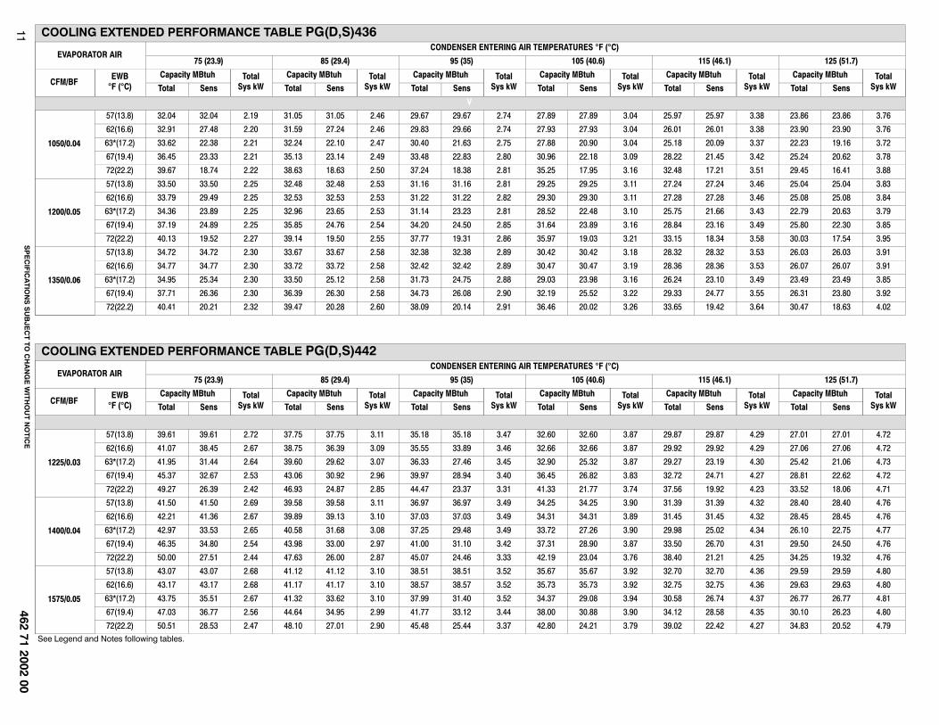
COOLING EXTENDED PERFORMANCE TABLE PG(D,S)424
EVAPORATOR AIRCONDENSER ENTERING AIR TEMPERATURES �F (�C)
* At 75°F (24°C) entering dry bulb-Tennessee Valley Authority (TVA) rating conditions; all others at 80°F dry bulb.
LEGENDBF— Bypass Factoredb— Entering Dry-BulbEwb— Entering Wet-BulbkW — Total Unit Power InputSHC— Sensible Heat Capacity (1000 Btuh)TC — Total Capacity (1000 Btuh) (net)rh—Relative Humidity
COOLING NOTES:1. Ratings are net; they account for the effects of the evaporator-fan motor power and heat.2. Direct interpolation is permissible. Do not extrapolate.
3. The following formulas may be used:
Sensible capacity (Btuh)
1.10 x cfmtldb = tedb -
Wet-bulb temperature corresponding to enthalpy
air leaving evaporator coil (hlwb)tlwb =
total capacity (Btuh)
4.5 x cfm
hlwb = hewb -
Where: hewb = Enthalpy of air entering evaporator coil
4. The SHC is based on 80�F (26.6�C) edb temperature of air entering evaporator coil. Below 80�F (26.6�C) edb,subtract (corr factor x cfm) from SHC. Above 80�F (26.6�C) edb, add (corr factor x cfm) to SHC. Correction Factor = 1.10 x (1 + BF) x (edb + 80).
5. Integrated capacity is maximum (instantaneous) capacity less the effect of frost on the outdoor coil and the heatrequired to defrost it.
SPECIFICATIONS SUBJECT TO CHANGE WITHOUT NOTICE13 462 71 2002 00
ACCESSORIES
ROOF CURBS
RETURN AIR
SMALLBASE UNIT
SUPPLYAIR
LARGEBASE UNIT
UNIT PLACEMENT ON COMMON CURB
C
B
A
F
D
E
LARGE CURB
C
B
A
F
DE
Dashed lines show cross supportlocation for large basepan units.
SMALL OR LARGE BASE UNIT
COMMON CURB
ROOF CURB DETAIL
Wood nailer*
Roofcurb*
Insulation(field supplied)
*Provided with roofcurb
Cant stripfield supplied
Roofing materialfield supplied
Flashing fieldsupplied
HVAC unitbase rails
Roofcurb
SealingGasket
HVAC unitbasepan
Anchor screw
A09090
A09095
A09096
A09094
A09097
UNIT SIZE CATALOGNUMBER
AIN. (mm)
B (small base)IN. (mm)*
B (large base)IN. (mm)*
CIN. (mm)
DIN. (mm)
EIN. (mm)
FIN. (mm)
Small or LargeCPRFCURB010A00 11 (279)
10 (254)14 (356) 16 (406) 47.8 (1214)
32.4 (822)2.7 (69)
CPRFCURB011A00 14 (356)
LargeCPRFCURB012A00 11 (279)
14 (356) 43.9 (1116)CPRFCURB013A00 14 (356)
* Part Numbers CPRCURB010A00 and CPRCURB011A00 can be used on both small and large basepan units. The cross supports must be located based on whether the unitis a small basepan or a large basepan.NOTES:
1. Roof curb must be set up for unit being installed.
2. Seal strip must be applied, as required, to unit being installed.
3. Roof curb is made of 16−gauge steel.
4. Attach ductwork to curb (flanges of duct rest on curb).
SPECIFICATIONS SUBJECT TO CHANGE WITHOUT NOTICE 14462 71 2002 00
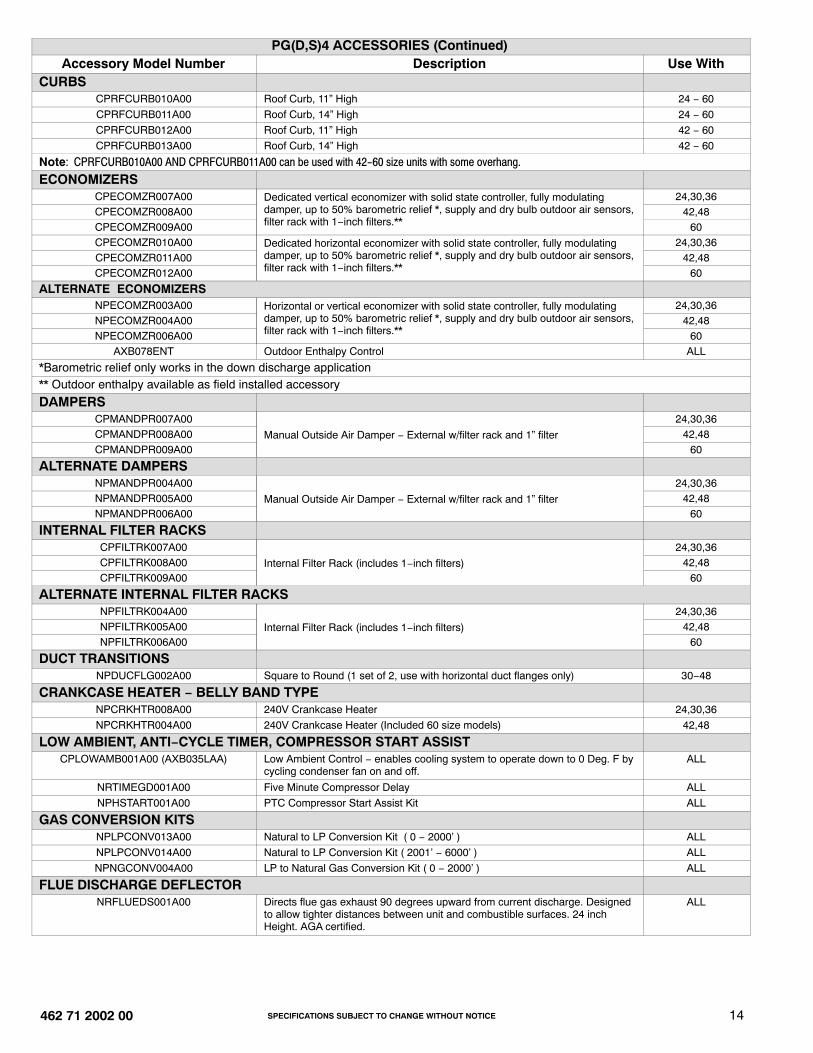
PG(D,S)4 ACCESSORIES (Continued)Accessory Model Number Description Use With
CURBS
CPRFCURB010A00 Roof Curb, 11” High 24 − 60
CPRFCURB011A00 Roof Curb, 14” High 24 − 60
CPRFCURB012A00 Roof Curb, 11” High 42 − 60
CPRFCURB013A00 Roof Curb, 14” High 42 − 60
Note: CPRFCURB010A00 AND CPRFCURB011A00 can be used with 42-60 size units with some overhang.
ECONOMIZERS
CPECOMZR007A00 Dedicated vertical economizer with solid state controller, fully modulatingdamper, up to 50% barometric relief *, supply and dry bulb outdoor air sensors,filter rack with 1−inch filters.**
24,30,36CPECOMZR008A00 42,48CPECOMZR009A00 60CPECOMZR010A00 Dedicated horizontal economizer with solid state controller, fully modulating
damper, up to 50% barometric relief *, supply and dry bulb outdoor air sensors,filter rack with 1−inch filters.**
24,30,36CPECOMZR011A00 42,48CPECOMZR012A00 60
ALTERNATE ECONOMIZERS
NPECOMZR003A00 Horizontal or vertical economizer with solid state controller, fully modulatingdamper, up to 50% barometric relief *, supply and dry bulb outdoor air sensors,filter rack with 1−inch filters.**
24,30,36NPECOMZR004A00 42,48NPECOMZR006A00 60
AXB078ENT Outdoor Enthalpy Control ALL
*Barometric relief only works in the down discharge application ** Outdoor enthalpy available as field installed accessory
DAMPERS
CPMANDPR007A00
Manual Outside Air Damper − External w/filter rack and 1” filter
24,30,36CPMANDPR008A00 42,48CPMANDPR009A00 60
ALTERNATE DAMPERS
NPMANDPR004A00
Manual Outside Air Damper − External w/filter rack and 1” filter
24,30,36NPMANDPR005A00 42,48NPMANDPR006A00 60
INTERNAL FILTER RACKS
CPFILTRK007A00
Internal Filter Rack (includes 1−inch filters)
24,30,36CPFILTRK008A00 42,48CPFILTRK009A00 60
ALTERNATE INTERNAL FILTER RACKS NPFILTRK004A00
Internal Filter Rack (includes 1−inch filters)
24,30,36NPFILTRK005A00 42,48NPFILTRK006A00 60
DUCT TRANSITIONS
NPDUCFLG002A00 Square to Round (1 set of 2, use with horizontal duct flanges only) 30−48
CPLOWAMB001A00 (AXB035LAA) Low Ambient Control − enables cooling system to operate down to 0 Deg. F bycycling condenser fan on and off.
ALL
NRTIMEGD001A00 Five Minute Compressor Delay ALL
NPHSTART001A00 PTC Compressor Start Assist Kit ALL
GAS CONVERSION KITS
NPLPCONV013A00 Natural to LP Conversion Kit ( 0 − 2000’ ) ALL
NPLPCONV014A00 Natural to LP Conversion Kit ( 2001’ − 6000’ ) ALL
NPNGCONV004A00 LP to Natural Gas Conversion Kit ( 0 − 2000’ ) ALL
FLUE DISCHARGE DEFLECTOR
NRFLUEDS001A00 Directs flue gas exhaust 90 degrees upward from current discharge. Designedto allow tighter distances between unit and combustible surfaces. 24 inchHeight. AGA certified.
ALL
SPECIFICATIONS SUBJECT TO CHANGE WITHOUT NOTICE15 462 71 2002 00
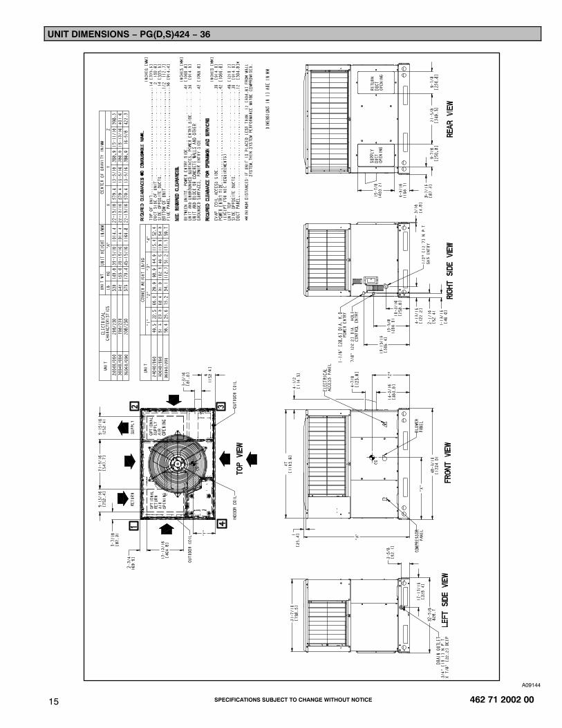
UNIT DIMENSIONS − PG(D,S)424 − 36
A09144
SPECIFICATIONS SUBJECT TO CHANGE WITHOUT NOTICE 16462 71 2002 00
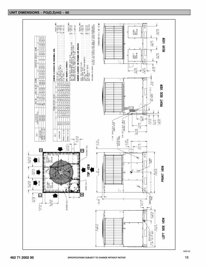
UNIT DIMENSIONS − PG(D,S)442 − 60
A09145
SPECIFICATIONS SUBJECT TO CHANGE WITHOUT NOTICE17 462 71 2002 00
TYPICAL WIRING SCHEMATIC − 208/230−1−60
A09282
SPECIFICATIONS SUBJECT TO CHANGE WITHOUT NOTICE 18462 71 2002 00
TYPICAL WIRING SCHEMATIC − 208/230−1−60 (CONT)
A09282
International Comfort Products, LLCLewisburg, Tennessee 37091 USA
www.GoICPCommercial.com
SPECIFICATIONS SUBJECT TO CHANGE WITHOUT NOTICE19 462 71 2002 00
CONTROLSOPERATING SEQUENCEHeating − On a call for heating, terminal “W” of the thermostat isenergized, starting the induced−draft motor. When the pressureswitch senses that the induced−draft motor is moving sufficientcombustion air, the burner sequence begins. This function isperformed by the integrated gas unit controller (IGC). The indoor(evaporator)−fan motor is energized 45 sec after flame isestablished. When the thermostat is satisfied and “W” isde−energized, the burners stop firing and the indoor(evaporator) fan motor shuts off after a 45−sec time−off delay.Please note that the IGC has the capability to automaticallyreduce the indoor fan motor on delay and increase the indoorfan motor off delay in the event of high duct static and/orpartially−clogged filter.Cooling − When the system thermostat calls for cooling, 24 V issupplied to the “Y1/Y” and “G” terminals of the thermostat. Thiscompletes the circuit to the contactor coil (C) and indoor(evaporator) fan relay (IFR). The normally open contacts ofenergized C close and complete the circuit through compressormotor (COMP) to outdoor (condenser) fan motor (OFM). Bothmotors start instantly. The set of normally open contacts ofenergized IFR close and complete the circuit through IFM. TheIFM starts instantly.
On the loss of the thermostat call for cooling, 24 V is removedfrom both the “Y1/Y” and “G” terminals (provided the fan switchis in the “AUTO” position) de−energizing the compressorcontactor and opening the contacts supplying power tocompressor/OFM. After a 90−second delay, the IFM shuts off. Ifthe thermostat fan selector switch is in the “ON” position, theIFM will run continuously.NOTE: On units with a anti−cycle timer: Once the compressorhas started and then stopped, it cannot be restarted again until 5minutes have elapsed.