SOILS, GEOLOGY AND SEISMICITY HOMEWOOD MOUNTAIN RESORT SKI AREA MASTER PLAN EIR/EIS SEPTEMBER 30, 2011 HAUGE BRUECK ASSOCIATES PAGE 14-1 14.0 SOILS, GEOLOGY AND SEISMICITY This chapter discloses the geologic, soil and seismic constraints on the Project and describes the physical characteristics of the Project area, including topography, geology, mineral resources, soils, seismicity, geologic hazards and existing land coverage. Proposed land coverage and Tahoe Regional Planning Agency (TRPA) land coverage limitations are also discussed. The Environmental Setting section provides information on the physical characteristics of the Project area, including geology, faults and history of earthquakes, soils and existing land coverage. The Regulatory Setting section outlines the regulatory framework of the State of California, the TRPA Code of Ordinances and the Placer County General Plan pertaining to geology, soils, seismicity, land capability and land coverage. The Impact Evaluation Criteria are based on the planning guidelines established by the State of California, TRPA and Placer County codified regulations and the TRPA thresholds for land coverage. Analyses of potential environmental impacts from the Project along with the standard engineering practices, compliance measures and recommended mitigation measures are presented in the Environmental Impacts and Recommended Mitigation section, followed by an analysis of cumulative impacts. 14.1 ENVIRONMENTAL SETTING 14.1.1 Physiography The Lake Tahoe Basin lies within the eastern portion of the Sierra Nevada geomorphic province. The surface of Lake Tahoe has an average elevation of about 6,225 feet above mean sea level (msl) (http://tahoe.usgs.gov/) with surrounding mountain peaks ranging from approximately 8,000 to 10,880 feet above msl. The basin, a large fault-bounded valley, trends north to south with an average width of 18 miles bounded on the west by the Sierra Nevada crest and on the east by the Carson Range and Mount Rose. The Homewood Mountain Resort (HMR) Ski Area Master Plan Area defines the Project area and is located on the west shore of Lake Tahoe in Placer County in the community of Homewood, California, approximately 19 miles north of South Lake Tahoe and 5 miles south of Tahoe City along State Route (SR) 89. Twenty parcels comprised of 42 Placer County Assessors Parcel Numbers or APNs make up the Project area. The Project area is located within the Homewood USGS 7.5 minute quadrangle map and lies within portions of Township 14 North and Range 16 East, Sections 1, 2, 10, 11, and 12 (Mount Diablo Meridian) with elevations ranging from approximately 6,235 feet to 7,880 feet above msl. The Project area functions as an active ski resort with ski trails, unpaved access roads, chair lifts, two lodge areas and paved and gravel parking lots. The surrounding area consists of commercial, residential and recreational land uses. The Project area watersheds have high average slopes of between 26% and 48% (see Figure 5, Appendix W). This is important because areas of steeper slope will generally produce more sediment than areas with a more gradual slope. The Project area occupies portions of the Madden Creek, Homewood Creek and Quail Lake Creek watersheds with general aspects trending southeast and northwest and average slopes of 48%, 47% and 45%, respectively. A distinct drainage area intervening between the lower portions of these watersheds is officially defined by TRPA and the Regional Water Quality Control Board – Lahontan Region (Lahontan) as Intervening Zone 7000. The Project area watersheds are defined in Figure 15-1 of Chapter 15, Hydrology, Water Rights, Surface Water Quality and Groundwater. Intervening Area 7000 has an average slope of 26% and general aspect of northeast (IERS 2010). The North and South Base areas, where most of the redevelopment is planned, are relatively
Transcript
SOILS, GEOLOGY AND SEISMICITY H O M E W O O D M O U N T A I N R E S O R T S K I A R E A M A S T E R P L A N E I R / E I S
S E P T E M B E R 3 0 , 2 0 1 1 H A U G E B R U E C K A S S O C I A T E S P A G E 1 4 - 1
14.0 SOILS, GEOLOGY AND SEISMICITY
This chapter discloses the geologic, soil and seismic constraints on the Project and describes the physical characteristics of the Project area, including topography, geology, mineral resources, soils, seismicity, geologic hazards and existing land coverage. Proposed land coverage and Tahoe Regional Planning Agency (TRPA) land coverage limitations are also discussed.
The Environmental Setting section provides information on the physical characteristics of the Project area, including geology, faults and history of earthquakes, soils and existing land coverage. The Regulatory Setting section outlines the regulatory framework of the State of California, the TRPA Code of Ordinances and the Placer County General Plan pertaining to geology, soils, seismicity, land capability and land coverage. The Impact Evaluation Criteria are based on the planning guidelines established by the State of California, TRPA and Placer County codified regulations and the TRPA thresholds for land coverage. Analyses of potential environmental impacts from the Project along with the standard engineering practices, compliance measures and recommended mitigation measures are presented in the Environmental Impacts and Recommended Mitigation section, followed by an analysis of cumulative impacts.
14.1 ENVIRONMENTAL SETTING
14.1.1 Physiography
The Lake Tahoe Basin lies within the eastern portion of the Sierra Nevada geomorphic province. The surface of Lake Tahoe has an average elevation of about 6,225 feet above mean sea level (msl) (http://tahoe.usgs.gov/) with surrounding mountain peaks ranging from approximately 8,000 to 10,880 feet above msl. The basin, a large fault-bounded valley, trends north to south with an average width of 18 miles bounded on the west by the Sierra Nevada crest and on the east by the Carson Range and Mount Rose.
The Homewood Mountain Resort (HMR) Ski Area Master Plan Area defines the Project area and is located on the west shore of Lake Tahoe in Placer County in the community of Homewood, California, approximately 19 miles north of South Lake Tahoe and 5 miles south of Tahoe City along State Route (SR) 89. Twenty parcels comprised of 42 Placer County Assessors Parcel Numbers or APNs make up the Project area. The Project area is located within the Homewood USGS 7.5 minute quadrangle map and lies within portions of Township 14 North and Range 16 East, Sections 1, 2, 10, 11, and 12 (Mount Diablo Meridian) with elevations ranging from approximately 6,235 feet to 7,880 feet above msl.
The Project area functions as an active ski resort with ski trails, unpaved access roads, chair lifts, two lodge areas and paved and gravel parking lots. The surrounding area consists of commercial, residential and recreational land uses. The Project area watersheds have high average slopes of between 26% and 48% (see Figure 5, Appendix W). This is important because areas of steeper slope will generally produce more sediment than areas with a more gradual slope. The Project area occupies portions of the Madden Creek, Homewood Creek and Quail Lake Creek watersheds with general aspects trending southeast and northwest and average slopes of 48%, 47% and 45%, respectively. A distinct drainage area intervening between the lower portions of these watersheds is officially defined by TRPA and the Regional Water Quality Control Board – Lahontan Region (Lahontan) as Intervening Zone 7000. The Project area watersheds are defined in Figure 15-1 of Chapter 15, Hydrology, Water Rights, Surface Water Quality and Groundwater. Intervening Area 7000 has an average slope of 26% and general aspect of northeast (IERS 2010). The North and South Base areas, where most of the redevelopment is planned, are relatively
SOILS, GEOLOGY AND SEISMICITY H O M E W O O D M O U N T A I N R E S O R T S K I A R E A M A S T E R P L A N E I R / E I S
P A G E 1 4 - 2 H A U G E B R U E C K A S S O C I A T E S S E P T E M B E R 3 0 , 2 0 1 1
flat. The existing Project area characteristics are illustrated in figures presented in Appendix W of this EIR/EIS, which contains the HMR Cumulative Watershed Effects (CWE) Analysis (IERS 2010) that was prepared in compliance with TRPA Ski Area Master Plan Guidelines (TRPA 1990). The following CWE Analysis figures are incorporated by reference:
• Figure A1. TMDL Defined Watersheds;
• Figure A2. Soil Parent Materials;
• Figure A3. Geology;
• Figure A4. Topography; and
• Figure A5. Slope Phase Map.
14.1.2 Geology
The Lake Tahoe Basin was formed two to three million years ago by geologic block faulting between the northwest-trending Sierra Nevada to the west and the north-trending Carson Ridge to the east. Lake Tahoe occupies the depression, or fault-produced graben, between these two uplifted mountain ranges. During the past two million years, glaciers played an active roll in shaping the Sierra Nevada Mountains and Lake Tahoe. Alpine glaciers extended below the current lake level along the west shoreline and Emerald Bay.
The basement geology of the Lake Tahoe Basin is divided into three categories: granitic, metamorphic and volcanic (Hyne et al. 1972). The majority of the Project area is underlain by Quaternary (2.6 million years to Present) glacial moraines and Miocene (23 to 5.3 million years) volcanic rocks (Kleinfelder 2007). Surface geology of the Project area consists primarily of andesite lahars/flows and breccias (Mva) and glacial till and moraines (Qg and Qti) and the area along the shore of Lake Tahoe and extending to the North Base area of the Project area is mapped as Quaternary-age lakebed deposits (Ql) (Kleinfelder 2007), as illustrated in Figure 14-1. Other minor geologic map units include alluvium, granitic rocks, metasedimentary rocks and older lake sediments.
14.1.3 Mineral Resources
The only known mineral resource in the vicinity of the Project area is gold. Lake Tahoe’s only gold mine was operated in the Project area in the 1940’s just south of Quail Lake (IERS 2010). USDA Forest Service Lake Tahoe Basin Management Unit (LTBMU) purchased this parcel in 2009, and therefore,. t The gold mine is not within the Project area.
14.1.4 Faults and Seismicity
Lake Tahoe Region
The potential for seismic activity within a Project area is primarily related to the proximity of faults. Faults are fractures or zones of related fractures where the rocks on one side have been displaced with respect to rocks on the other side. The California State Mining and Geology Board define an “active fault” as one that has had surface displacement within the past 11,000 years, the Holocene. Potentially active faults are defined as those that have ruptured between 11,000 and
SOILS, GEOLOGY AND SEISMICITY H O M E W O O D M O U N T A I N R E S O R T S K I A R E A M A S T E R P L A N E I R / E I S
S E P T E M B E R 3 0 , 2 0 1 1 H A U G E B R U E C K A S S O C I A T E S P A G E 1 4 - 3
1.6 million years before the present (Quaternary). Faults are generally considered inactive if there is no evidence of displacement during the Quaternary period.
The Lake Tahoe Basin is located in a region of Holocene age and early Quaternary age, as evidenced by the features and historical data published in Natural Hazards of the Lake Tahoe Basin (Cooper, Clark and Associates 1974) and Preliminary Maps of Pleistocene to Holocene Faults in the Lake Tahoe Basin, California and Nevada (Saucedo 2005):
• Movements have taken place along faults adjacent to the basin within historical time (Lawson 1912; Kachadoorian 1967);
• Sediments at the bottom of Lake Tahoe show offsets or displacements that are indicative of faulting (Hyne 1972); and
• Steep cliffs (30 to 45-degree slopes) and other topographic features associated with active faulting are found on both sides of Lake Tahoe (Hyne et al. 1972).
A north-south fault zone, located about six miles east of the Lake Tahoe Basin, separates the eastern edge of the Sierra Nevada from the parallel fault-block mountains of Nevada and Utah. The north-south faults along the shores of Lake Tahoe appear to be the longest continuous faults traversing the basin area. Of these faults, the fault along the west side of the lake appears to be the longest, with a surface length of approximately 50 miles. A fault of this length could potentially generate a 7.5 magnitude earthquake (Cooper, Clark and Associates 1974).
Ground shaking resulting from an earthquake is typically described by two methods: ground acceleration as a fraction of the acceleration of gravity (g) or the Modified Mercalli scale, which is a more descriptive method involving 12 levels of intensity denoted by Roman numerals (see Table 14-1). The scale relates human perception and amount of damage. Modified Mercalli intensities range from I (shaking that is not felt) to XII (total damage). The Richter Scale is still used to describe earthquakes in the mass media. The Richter magnitude scale, also known as the local magnitude scale, assigns a single number to quantify the amount of seismic energy released by an earthquake. Table 14-1 provides a crosswalk between the Richter Scale and the Modified Mercalli scale.
As depicted in Table 14-1, a Richter magnitude of 7.0 to 7.9 corresponds to IX – X intensity on the Modified Mercalli scale. This intensity of an earthquake could shift buildings off foundations, break underground pipes, and trigger landslides on steep slopes (Burnett 1973). A very young fault scarp on the east side of the Carson Range provides evidence that large and potentially destructive earthquakes have occurred in this region during the last 11,000 years.
Numerous earthquakes have occurred in the Lake Tahoe Basin during the past 100 years of record keeping. These earthquakes generally measured less than 5.0 on the Richter scale. A catalog search of the USGS National Earthquake Information Center (http://earthquake.usgs.gov/regional/neic/ accessed on 11/2/2009) revealed no earthquakes greater than 5.0 magnitudes within the Project area or Tahoe Basin (latitude 39.0672 and longitude –120.2360). Approximately 1,144 minor earthquakes of less than 5.0 magnitude and 15 major earthquakes of magnitude 5.0 or greater have occurred since 1974.
SOILS, GEOLOGY AND SEISMICITY H O M E W O O D M O U N T A I N R E S O R T S K I A R E A M A S T E R P L A N E I R / E I S
P A G E 1 4 - 4 H A U G E B R U E C K A S S O C I A T E S S E P T E M B E R 3 0 , 2 0 1 1
Table 14-1
Modified Mercalli Intensity Scale
Rating Description of Damage or Human Perception
I. Not felt except by a very few under especially favorable circumstances.
II. Felt only by a few persons at rest, especially on upper floors of buildings. Delicately suspended object may swing.
III. Felt quite noticeably indoors, especially on upper floors of buildings, but many people do not recognize it as an earthquake. Standing motorcars may rock slightly. Vibration like passing of truck. Duration estimated.
IV. During the day felt indoors by many, outdoors by few. At night some awakened. Dishes, windows, doors disturbed; walls make creaking sound. Sensation like heavy truck striking building. Standing motorcars rocked noticeably.
V. Felt by nearly everyone, many awakened. Some dishes, windows, and so on broken; cracked plaster in a few places; unstable objects overturned. Disturbances of trees, poles, and other tall objects sometimes notices. Pendulum clocks may stop.
VI. Felt by all, many frightened and run outdoors. Some heavy furniture moved; a few instances of fallen plaster and damaged chimneys. Damage slight.
VII. Everybody runs outdoors. Damage negligible in buildings of good design and construction; slight to moderate in well built ordinary structures; considerable in poorly built or badly designed structures; some chimneys broken. Noticed by persons driving cars.
VIII. Damage slight in specially designed structures; considerable in ordinary substantial buildings with partial collapse; great in poorly built structures. Panel walls thrown out of frame structures. Fall of chimneys, factory stacks, columns, monuments, walls. Heavy furniture overturned. Sand and mud ejected in small amounts. Changes in well water. Persons driving cars disturbed.
IX. Damage considerable in specially designed structures; well designed frame structures thrown out of plumb; great in substantial buildings, with partial collapse. Buildings shifted off foundations. Ground cracked conspicuously. Underground pipes broken.
X. Some well built wooden structures destroyed; most masonry and frame structures destroyed with foundations; ground badly cracked. Rails bent. Landslides considerable from river banks and steep slopes. Shifted sand and mud. Water splashed, slopped over banks.
XI. Few, if any, (masonry) structures remain standing. Bridges destroyed. Broad fissures in ground. Underground pipelines completely out of service. Earth slumps and land slips in soft ground. Rails bent greatly.
XII. Damage total. Waves seen on ground surface. Lines of sight and level distorted. Objects thrown into the air.
RICHTER MAGNITUDE INTENSITY
(Maximum expected Modified Mercalli)
3.0 – 3.9 II -III
4.0 – 4.9 IV - V
5.0 – 5.9 VI - VII
6.0 – 6.9 VII - VIII
7.0 – 7.9 IX – X
8.0 – 8.9 XI - XII
Source: Burnett 1973; U.S. Geological Survey 1974
SOILS, GEOLOGY AND SEISMICITY H O M E W O O D M O U N T A I N R E S O R T S K I A R E A M A S T E R P L A N E I R / E I S
S E P T E M B E R 3 0 , 2 0 1 1 H A U G E B R U E C K A S S O C I A T E S P A G E 1 4 - 5
Project Area
The Project area is located in a region that is traditionally characterized by moderate to high seismic activity (ICC 2006) and lies within a zone of influence of numerous other regional fault systems in eastern California and western Nevada. A Geologic Hazards and Preliminary Geotechnical Evaluation was completed for the general Project area on October 15, 2007 (Kleinfelder 2007). The purpose of the evaluation was to identify and assess potential geologic hazards at the site in accordance with the requirements of the California Board for Geologists and Geophysicists (Board) Geologic Guidelines for Earthquake and/or Fault Hazard Reports; the Board Guidelines for Engineering Geologic Reports; California Geological Survey (CGS) Special Publication 42, Fault-Rupture Hazard Zones in California: Alquist-Priolo Earthquake Fault Zoning Act with index to Earthquake Fault Zone Maps (Hart and Bryant 1997); and CGS Special Publication 117, Guidelines for Evaluating and Mitigating Seismic Hazards in California (California Division of Mines and Geology 1997). The secondary purpose was to comply with Placer County Community Development Resource Agency guidelines for a Preliminary Geotechnical Report. The Kleinfelder preliminary report is referenced for information about the general Project area.
Holdredge and Kull completed follow up geotechnical investigations specifically for the North Base and Mid-Mountain areas in 2009 in consideration of proposed site-specific design and construction. geotechnical evaluations for the North Base and Mid-Mountain areas in 2009 and reported findings in Geotechnical Engineering Report for North Base Lodge, Homewood Mountain Resort (Holdrege and Kull 2010a) and Geotechnical Engineering Report for Mid-Mountain Lodge, Homewood Mountain Resort (Holdrege and Kull 2010b). The Holdredge and Kull reports are referenced for site-specific information for the North Base and Mid-Mountain areas being redeveloped during Phase 1 of the Project.
Figure 14-1 depicts mapped active faults in the vicinity of the Project area: the West Tahoe-Dollar Point fault zone (3.0 miles east of the Project area); the North Tahoe fault (4.8 miles northeast of the Project area); and the Incline Village fault (10.3 miles northeast of the Project area). Figure 14-1 also illustrates the location of two unnamed faults mapped across the Project area. Unnamed Fault 1 trends generally north-south across the west side of Quail Lake past the Mid-Mountain area and continues off-site to the west. Unnamed Fault 2 trends generally north-south across the eastern portion of the Project area and is mapped near the break in slope located to the west of the two base areas.
To evaluate the location of Unnamed Fault 1 relative to the North Base area, Holdrege and Kull reviewed the following maps:
• Fault Activity Map of California and Adjacent Areas; by Charles W. Jennings, California Department of Conservation, Division of Mines and Geology, 1994;
• Geologic Map of the Chico Quadrangle, California, by G.J. Saucedo and D.L. Wagner, California Division of Mines and Geology, 1992;
• Geologic Map of the Lake Tahoe Basin, California and Nevada, by G.J. Saucedo, California Geological Survey, 2005; and
• New Constraints on Deformation, Slip Rate, and Timing of the Most Recent Earthquake on the West Tahoe – Dollar Point Fault, Lake Tahoe Basin, California, by Daniel S. Brothers, et. al., Bulletin of the Seismological Society of America, April 2009.
SOILS, GEOLOGY AND SEISMICITY H O M E W O O D M O U N T A I N R E S O R T S K I A R E A M A S T E R P L A N E I R / E I S
P A G E 1 4 - 6 H A U G E B R U E C K A S S O C I A T E S S E P T E M B E R 3 0 , 2 0 1 1
To evaluate the location of Unnamed Fault 2 relative to the Mid-Mountain area, Holdrege and Kull reviewed the following maps:
• Fault Activity Map of California and Adjacent Areas; by Charles W. Jennings, California Department of Conservation, Division of Mines and Geology, 1994; and
• Geologic Map of the Chico Quadrangle, California, by G.J. Saucedo and D.L. Wagner, California Division of Mines and Geology, 1992.
The Alquist-Priolo Earthquake Fault Zoning Act (1972) also defines an active fault as one that has had surface displacement within the last 11,000 years. Holdredge and Kull (2010a, 2010b) reviewed the 1997 version of Special Publication 42, Fault Rupture Hazard Zones in California, which describes active faults and fault zones, as part of the Alquist-Priolo Earthquake Fault Zoning Act and the document and the 1999 on-line update indicate that the Project area is not located in an Alquist-Priolo active fault zone.
14.1.5 Geologic Hazards
The most significant geologic hazards associated with the Project area are from earthquakes and their associated effects (Holdredge and Kull 2010a, 2010b; Kleinfelder 2007). Earthquakes present direct (primary) and indirect (secondary) hazards; both of which can occur locally or at locations distant from the earthquake source. Direct, local earthquake hazards include damage caused by fault displacements either by ground surface rupture or gradual fault creep. The damage caused by ground shaking is also a direct effect; however, shaking can occur locally or at remote locations. Indirect hazards presented by earthquakes include liquefaction and earthquake-induced landslides, both of which are triggered by ground shaking. The portions of the Project area that are located on or near steep terrain could be subject to slope instability (landsliding, both gravitational or earthquake-induced) hazards. Roads, distribution pipelines, utilities lines and snowmaking pipelines could also be subject to this hazard. The analysis of these hazards is based on an understanding of the potential for any or all of these events to occur in the Project area.
Fault Rupture
The potential for fault rupture is related to concepts of recency and recurrence (Holdrege and Kull 2010a), meaning that the more recently a fault has ruptured, the more likely that the fault could rupture again. Displacement caused by fault rupture or fault creep could occur along future pipelines for snowmaking and utilities that must cross fault zones. In Kleinfelder (2007) reviewed aerial photos of the Project area dating from 1939, 1966, 1987, 1995, 2000 and 2005. No evidence of fault rupture of Holocene features was observed on any of the photos.
The geologic maps referenced by Holdredge and Kull (2010a, 2010b) show several active and potentially active faults located near, but not within, the Project area, including the Dog Valley Fault (active, approximately 20 miles north-northwest), a group of unnamed faults southeast of Truckee (potentially active, approximately 15 miles north), the West Tahoe-Dollar Point Fault (active, approximately 3 miles east), and the North Tahoe Fault (active, approximately 4.5 miles northeast). The Genoa Fault trends in a north-south direction approximately 18 miles east of the site and is capable of very large earthquakes. Earthquakes associated with these faults may cause strong ground shaking at the project area.
SOILS, GEOLOGY AND SEISMICITY H O M E W O O D M O U N T A I N R E S O R T S K I A R E A M A S T E R P L A N E I R / E I S
S E P T E M B E R 3 0 , 2 0 1 1 H A U G E B R U E C K A S S O C I A T E S P A G E 1 4 - 7
Figure 14-1. Project Area Geology and Fault Map
SOILS, GEOLOGY AND SEISMICITY H O M E W O O D M O U N T A I N R E S O R T S K I A R E A M A S T E R P L A N E I R / E I S
P A G E 1 4 - 8 H A U G E B R U E C K A S S O C I A T E S S E P T E M B E R 3 0 , 2 0 1 1
Unnamed Fault 1 (see Figure 14-1) is shown on the Geologic Map of the Lake Tahoe Basin (Saucedo, 2005) as discontinuous and trending in a northwest direction near the base of the slope through the project area. Unnamed Fault 1 is considered to be of Quaternary-age, relatively short, about one mile long, and is shown as approximately located (dashed) and uncertain as to existence (queried) on the Saucedo (2005) map. Unnamed Fault 1 is not shown on the Chico Quadrangle Map (Saucedo and Wagner, 1992). Unnamed Fault 2, considered to be of Quarternary age, is not shown on referenced maps as crossing or trending towards the Mid-Station Base area (Holdrege and Kull 2010b). Again, quaternary age faults are considered potentially active.
Ground Shaking
The severity of ground shaking due to an earthquake is determined by several factors including the size of the earthquake, fault rupture characteristics, and proximity of the earthquake to the site of interest. Additionally, the type of soil or bedrock beneath the site will determine the strength of ground shaking.
As discussed previously, ground shaking is typically described by two methods: ground acceleration as a fraction of the acceleration of gravity (g) or the Modified Mercalli scale, which is a more descriptive method involving 12 levels of intensity denoted by Roman numerals (see Table 14-1). The scale relates human perception and amount of damage. Modified Mercalli intensities range from I (shaking that is not felt) to XII (total damage).
The Lake Tahoe Basin is classified as Zone III on the State of California's Earthquake Epicenters, Faults, and Intensity Zone Map (December 2008). Zone III is a high intensity zone, with a probable maximum earthquake intensity of IX or X on the Modified Mercalli Scale, which corresponds to maximum momentum magnitudes of 7.0 to 7.9 on the Richter scale as detailed in Table 14-1 (Burnett 1973).
The International Building Code’s Seismic Zone Map of the United States places Placer County, including the Project area, within Seismic Hazard Zone III, which corresponds to an area that may experience damage due to earthquakes having moderate intensities of V or more on Modified Mercalli Scale, which corresponds to maximum momentum magnitudes of 4.9 or greater (IBC 2006).
The North Tahoe and Incline Village faults have estimated maximum momentum magnitudes of 7.0 and 6.6, respectively. The slip rate category for the North Tahoe and Incline faults is 0.2 to 1.0 millimeters per year (mm/yr) (Kleinfelder 2007). The Project area is mapped as having a probable maximum earthquake intensity of IX or X on the Modified Mercalli scale, indicating that damage could occur to structures and cracks could form in foundations (Kleinfelder 2007).
For earthquake engineering, an important input parameter is Peak Ground Acceleration (PGA), which is a measure of earthquake acceleration on the ground. PGA is a measure of how hard the earth shakes in a given geographic area rather than a measure of the total size of an earthquake (http://www.consrv.ca.gov/cgs/rghm/psha/Pages/pga.aspx). The California Geological Survey maintains a web-based computer model that estimates probabilistic seismic ground motions for any location within California. The computer model estimates the “Design Basis Earthquake” ground motion, which is defined as the PGA with a ten percent chance of exceedance in 50 years (475-year return period). For an alluvial/colluvial soil type found within the Project area, the estimated design PGA is approximately 0.316g; thus indicating that the ground-shaking hazard in the Project area is moderate (Holdrege and Kull 2010a; California Geological Survey 2007).
SOILS, GEOLOGY AND SEISMICITY H O M E W O O D M O U N T A I N R E S O R T S K I A R E A M A S T E R P L A N E I R / E I S
S E P T E M B E R 3 0 , 2 0 1 1 H A U G E B R U E C K A S S O C I A T E S P A G E 1 4 - 9
Liquefaction
Liquefaction occurs in water-saturated sediments that are shaken by moderate to large earthquakes. The liquefied soil loses shear strength when subjected to cyclic loading and may become unstable and fail, causing damage to all types of structures. Liquefaction was responsible for much of the damage during the 1906 San Francisco earthquake and the 1989 Loma Prieta earthquake. Liquefaction hazard analysis involves understanding the potential for ground shaking combined with the physical properties and conditions of the soil. In order for liquefaction to occur, two criteria must be met. First, there must be an opportunity for liquefaction to occur, and second, the soil must be susceptible to liquefaction. The main factors affecting liquefaction potential of a soil are level and duration of seismic ground motions, soil type and consistency, and depth to groundwater. Soils most susceptible to liquefaction are saturated, loose, clean, uniformly graded, and fine-grained sand deposits. Geologic age also influences the potential for liquefaction. Sediments deposited within the past few thousand years are generally much more susceptible to liquefaction than older Holocene sediments; Pleistocene sediments are even more resistant; and pre-Pleistocene sediments are generally immune to liquefaction (California Division of Mines and Geology 1997).
Holdrege and Kull (2010a, 2010b) completed subsurface explorations at the North Base and Mid-Mountain area in October 2009. The results indicate that the potential for liquefaction is low at the Mid-Mountain and North Base area.
Seismically-Induced Landslides, Debris Flows, Soil Creep and Rock Fall
Slope instability includes landslides, debris flows, soil creep and rock fall. Kleinfelder (2007) completed a geologic hazards and preliminary geotechnical evaluation across the general Project area. Because of the topography of the Project area and observed evidence of soil creep, the possibility of landslides and seismically-induced slope instability is considered moderate. A Quaternary landslide is mapped in the volcanic rocks to the north of the Project area. The same rock type is mapped within the Project area and could be prone to landslides (Kleinfelder 2007). Areas of rock outcrop existing in the Project area, and the potential for seismically-induced rock fall exists (Kleinfelder 2007). Evidence of soil creep (e.g. bent tree trunks) was observed on “The Face” ski trail near the top of the slope below the mid-loading station of the Madden Triple Chair Lift.
Holdredge and Kull completed geotechnical engineering evaluations at the North Base and Mid-Mountain areas (2010a, 2010b). No recent landslides, debris flows or rock fall hazards were observed in these areas. Holdredge and Kull conclude that due to the granular and rocky nature and relative competency of the underlying rock at the proposed development sites and general surrounding area, the potential for slope instability is considered low. For the Mid-Mountain, which is located on a topographically high ridge, the rock fall hazard is considered negligible. The North Base area is located at the base of a moderately steep slope and similar to many locations in mountainous terrain, seismically induced rock fall is a potential hazard. However, no rock outcrops are located on the slope above the North Base area and the potential hazard from seismically induced rock fall is considered low.
14.1.6 Surface Soils
This subsection addresses surface soils as they relate to geotechnical engineering and design constraints within the redevelopment and development portions of the Project area. Soils in the Lake Tahoe Region have most recently been mapped by the United States Department of Agriculture’s (USDA) Natural
SOILS, GEOLOGY AND SEISMICITY H O M E W O O D M O U N T A I N R E S O R T S K I A R E A M A S T E R P L A N E I R / E I S
P A G E 1 4 - 1 0 H A U G E B R U E C K A S S O C I A T E S S E P T E M B E R 3 0 , 2 0 1 1
Resource Conservation Service (NRCS) and are described in the Soil Survey of the Tahoe Basin Area, California and Nevada (USDA 2007). This most recent soil survey is used for the basis of this chapter. It is important to note, however, that for land capability, coverage and permitting purposed TRPA uses the Bailey Land Capability system, which relies on the Soil Survey of the Tahoe Basin Area, California and Nevada (Rogers 1974). The 2007 soil survey is being proposed for adoption and integration into the Bailey Land Capability System as part of the TRPA Regional Plan Update.
Lake Tahoe Basin soils are complex and diverse. Variability in relief, vegetative cover, and climate are major factors influencing the region's soil diversity. Great differences in soil properties can occur within short distances. Some soils are seasonally wet or subject to flooding. Some have shallow depths to bedrock. Some are too unstable to be used as a foundation for buildings or roads. A high water table makes a soil poorly suited to basements or underground installations.
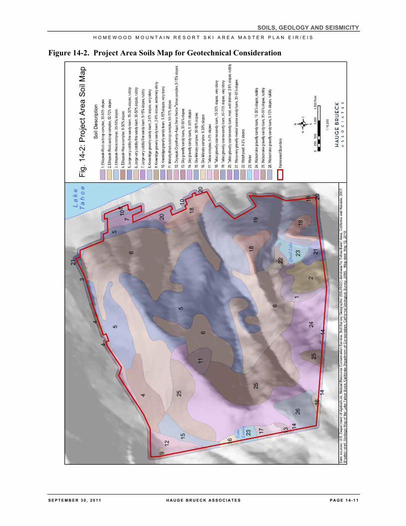
Volcanic-derived soils comprise the majority of the Project area with some areas along the northwest boundary and below Quail Lake determined as a mix of volcanic and glacial. Based on the NRCS Soil Survey (2007) there are two primary soil series in the Project area, Tallac and Jorge series soils. Soils in the vicinity of existing and/or proposed development in Project area have been reviewed as part of various geotechnical, hydrologic and TRPA land capability analyses (See Davis 2006; Kleinfelder 2007; Holdredge and Kull 2010a, 2010b; and Appendix D of this EIR/EIS for soil investigation locations and results). Generally speaking, results of these reports found that the soils within the Project area are suitable for development with implementation of standard site-specific geotechnical recommendations. Figure 14-2 shows the distribution of the soil groups in the Project area that are described in Table 14-1. Geotechnical recommendations are discussed in the Environmental Impacts and Recommended Mitigation subsection below.
Soil investigations determine that across the North Base area soils are generally very deep and well-drained, derived from colluvium of reworked andesitic materials in the upper layers. Old lakebed deposits are buried at depth. Soils are characterized as having dark brown gravelly sandy loam about 16 inches thick over dark yellowish brown gravelly or very gravelly subsoil abruptly underlain by gravelly, very gravelly or extremely gravelly loamy coarse sand at depths varying from 43 to 60 inches. These soils are members of Soil Hydrologic Groups A and B. One isolated area displayed finer grained sediments within about 30 inches of the natural surface in a small isolated area just south of the North Lodge site, resembling JgC (Jabu gravelly sandy loam, moderately fine subsoil variant, two to nine percent slope), which places the soil within Soil Hydrologic Group C. For the most part, soils were found to be deep and to lack enough coarse fragments in the control section to be skeletal. They are deep soils, as opposed to the former Umpa series, which is moderately deep (20 to 40 inches) and formed on andesitic bedrock. None of the soil profiles in the base areas examined displayed restrictive subsurface layering or fragipans that are typical of the Tallac series.
Soil map units within the Project area are not considered expansive. The shrink-swell potential is notably low (see Table 14-2). Expansive materials are those that could pose a risk to structural damage due to their significant clay content, which can result in swelling and compression during changes in moisture content.
Some soil map units within the Project area are considered moderate to highly corrosive to steel and concrete, as detailed in Table 14-2. Soil corrosion is a complex phenomenon that involves a multitude of variables. Soil resistivity is a parameter for estimating the corrosivity of soils. Soils with high sand and moisture content, high electrical conductivity, high acidity, and high dissolved salts are considered to be the most corrosive.
SOILS, GEOLOGY AND SEISMICITY H O M E W O O D M O U N T A I N R E S O R T S K I A R E A M A S T E R P L A N E I R / E I S
S E P T E M B E R 3 0 , 2 0 1 1 H A U G E B R U E C K A S S O C I A T E S P A G E 1 4 - 1 1
Figure 14-2. Project Area Soils Map for Geotechnical Consideration
SOILS, GEOLOGY AND SEISMICITY H O M E W O O D M O U N T A I N R E S O R T S K I A R E A M A S T E R P L A N E I R / E I S
P A G E 4 . 2 - 1 2 H A U G E B R U E C K A S S O C I A T E S S E P T E M B E R 3 0 , 2 0 1 1
Table 14-2
NRCS Soils in the Project Area
Soil Type1 Parent
material2
Surface Runoff Class3
Slowest Permeability
4
Shrink-Swell
Potential5
Corrosivity6
Drainage
Class7
Available Water
Capacity8 Hydrologic Soil Group9
Watah Peat 0 to 2% slopes
Organic Material over
alluvium derived from
mixed sources
Very High Moderate Low High/High Very poorly drained
5.8 inches Moderate
A/D
Ellispeak-Rock Outcrop Complex 30 to 50% slopes
Colluvium derived from welded tuff and/or lahar
Very High Rapid above the bedrock
Low Moderate/Low Excessively drained
0.8 inches Very Low
D
Ellispeak-Rock Outcrop Complex 50 to 70% slopes
Colluvium derived from welded tuff and/or lahar
Very High Rapid above the bedrock
Low Moderate/Low Excessively drained
0.8 inches Very Low
D
Ellis Peak-Waca Complex
9 to 30% slopes
Colluvium derived from welded tuff and/or lahar
Very High Rapid above the bedrock
Low Moderate/Low Excessively drained
0.8 inches Very Low
D
Ellis Peak-Waca Complex
30 to 50% slopes
Colluvium derived from welded tuff and/or lahar
Very High Rapid above the bedrock
Low Moderate/Low Excessively drained
0.8 inches Very Low
D
Jabu* Gravelly Sandy
Loam Moderately Fine Subsoil Variant 2 to 9% slopes
Outwash derived from granodiorite
Low Very Slow Low Well Drained
5.4 inches Moderate
A
SOILS, GEOLOGY AND SEISMICITY H O M E W O O D M O U N T A I N R E S O R T S K I A R E A M A S T E R P L A N E I R / E I S
S E P T E M B E R 3 0 , 2 0 1 1 H A U G E B R U E C K A S S O C I A T E S P A G E 4 . 2 - 1 3
Soil Type1 Parent
material2
Surface Runoff Class3
Slowest Permeability
4
Shrink-Swell
Potential5
Corrosivity6
Drainage
Class7
Available Water
Capacity8 Hydrologic Soil Group9
Jorge Very cobbly fine
sandy loam 5 to 15% slopes
Colluvium derived from
andesite
Low Moderate Low Moderate/Low Well drained
5.7 inches Moderate
B
Jorge Very cobbly fine
sandy loam 15 to 30% slopes
Colluvium derived from
andesite
Medium Moderate Low Moderate/Low Well drained
5.7 inches Moderate
B
Jorge Very cobbly fine
sandy loam 30 to 50% slopes
Colluvium derived from
andesite
Medium Moderate Low Moderate/Low Well drained
5.7 inches Moderate
B
Kneeridge Gravelly medial
sandy loam 2 to 9% slopes
Extremely stony
Colluvium and/or till
derived from andesite
Low Moderate Low Moderate/ High
Moderately well
drained
9.5 inches High
A
Kneeridge Gravelly medial
sandy loam 2 to 5% slopes
Very stony
Colluvium and/or till
derived from andesite
Low Moderate Low Moderate/ High
Moderately well
drained
9.5 inches High
A
Kneeridge Gravelly medial
sandy loam 5 to 15% slopes
Very stony
Colluvium and/or till
derived from andesite
Low Moderate Low Moderate/ High
Moderately well
drained
9.5 inches High
A
Tallac Gravelly coarse
sandy loam
Colluvium over till derived from mixed sources
Medium Slow Low Moderate/ Moderate
Well drained
3.2 inches Low
A
SOILS, GEOLOGY AND SEISMICITY H O M E W O O D M O U N T A I N R E S O R T S K I A R E A M A S T E R P L A N E I R / E I S
P A G E 4 . 2 - 1 4 H A U G E B R U E C K A S S O C I A T E S S E P T E M B E R 3 0 , 2 0 1 1
Soil Type1 Parent
material2
Surface Runoff Class3
Slowest Permeability
4
Shrink-Swell
Potential5
Corrosivity6
Drainage
Class7
Available Water
Capacity8 Hydrologic Soil Group9
15 to 30% slopes
Tallac Gravelly coarse
sandy loam 30 to 70% slopes
Very stony
Colluvium over till derived from mixed sources
Medium Slow Low Moderate/ Moderate
Well drained
3.2 inches Low
A
Tallac Gravelly coarse
sandy loam moderately well
drained 2 to 9% Rubbly
Colluvium over till derived from mixed sources
Medium Slow Low Moderate/ Moderate
Well drained
3.2 inches Low
A
Oxyaquic Cryorthents-Aquic Xerorthents-Tahoe
Complex 0 to 15%
Alluvium and/or
colluvium derived from
mixed sources
High Moderate Low Moderate/ Moderate
Somewhat poorly drained
2.5 inches Low
A
Watsonlake Gravelly sandy
loam 5 to15% slopes
Rubbly
Collivum derived from
andesite
Low Slow above bedrock
Low Moderate/Low Well drained
6.9 inches Moderate
B
Watsonlake Gravelly sandy
loam 15 to 30% slopes
Rubbly
Collivum derived from
andesite
Medium Slow above bedrock
Low Moderate/Low Well drained
6.9 inches Moderate
B
Watsonlake Gravelly sandy
Collivum derived from
andesite
Medium Slow above bedrock
Low Moderate/Low Well drained
6.9 inches Moderate
B
SOILS, GEOLOGY AND SEISMICITY H O M E W O O D M O U N T A I N R E S O R T S K I A R E A M A S T E R P L A N E I R / E I S
S E P T E M B E R 3 0 , 2 0 1 1 H A U G E B R U E C K A S S O C I A T E S P A G E 4 . 2 - 1 5
Table Notes: * Jabu identified during soil investigations for the land capability challenge in the North Base area (previously identified as Umpa). 1. See Figure 14-2 for locations 2. Parent material. The unconsolidated and chemically weathered mineral and organic material in which the solum of a soil is formed as a result of pedogenic processes. Granitic. A textural term
commonly pertaining to an igneous intrusive rock of felsic to intermediate composition. Referring to granite like rock, but not necessarily true granite. Commonly applied to granite, quartz monzonite, granodiorite, and diorite. Granodiorite. An igneous intrusive rock that is intermediate between felsic and mafic in composition and contains quartz and somewhat more plagioclase than orthoclase.
3. Runoff. The precipitation discharged into stream channels from an area. The water that flows off the surface of the land without sinking into the soil is called surface runoff. Water that enters the soil before reaching surface streams is called ground-water runoff or seepage flow from ground water.
4. Permeability. The quality of the soil that enables water or air to move downward through the profile. The rate at which a saturated soil transmits water is accepted as a measure of this quality.
SOILS, GEOLOGY AND SEISMICITY H O M E W O O D M O U N T A I N R E S O R T S K I A R E A M A S T E R P L A N E I R / E I S
P A G E 4 . 2 - 1 6 H A U G E B R U E C K A S S O C I A T E S S E P T E M B E R 3 0 , 2 0 1 1
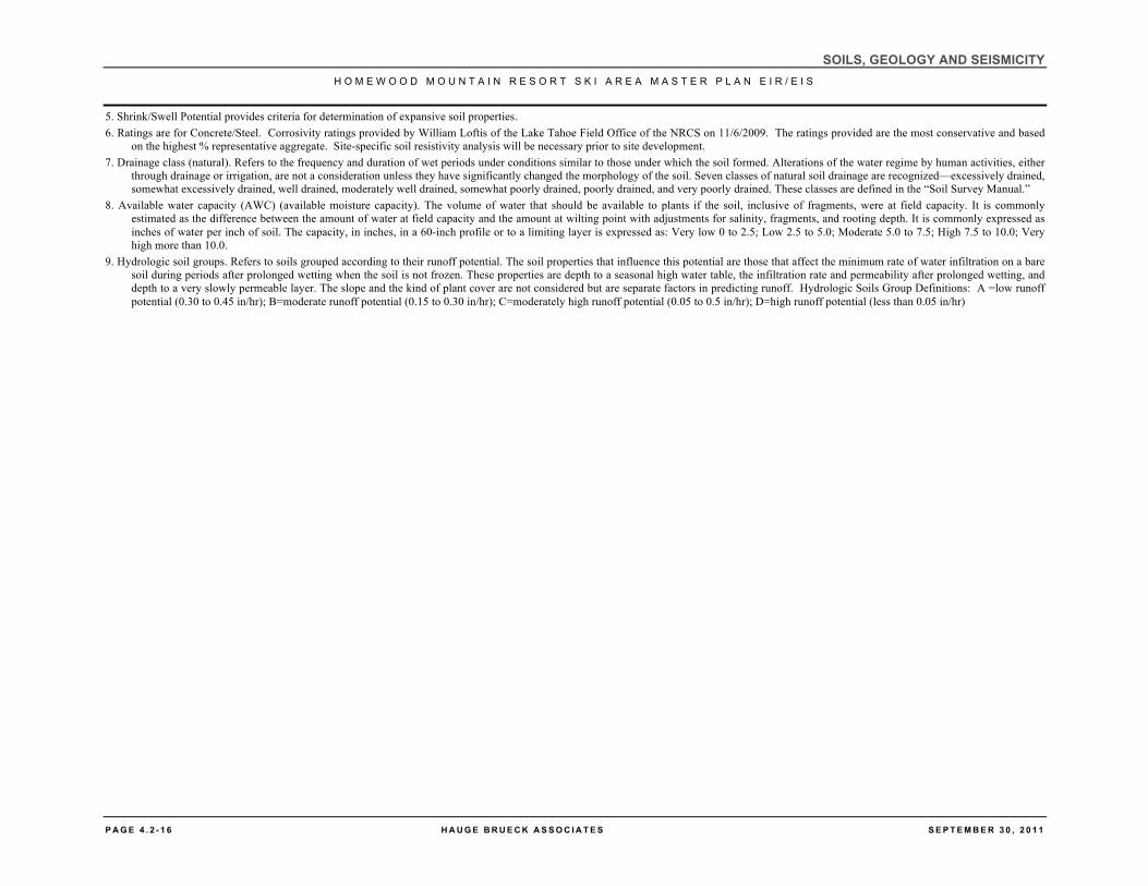
5. Shrink/Swell Potential provides criteria for determination of expansive soil properties. 6. Ratings are for Concrete/Steel. Corrosivity ratings provided by William Loftis of the Lake Tahoe Field Office of the NRCS on 11/6/2009. The ratings provided are the most conservative and based
on the highest % representative aggregate. Site-specific soil resistivity analysis will be necessary prior to site development. 7. Drainage class (natural). Refers to the frequency and duration of wet periods under conditions similar to those under which the soil formed. Alterations of the water regime by human activities, either
through drainage or irrigation, are not a consideration unless they have significantly changed the morphology of the soil. Seven classes of natural soil drainage are recognized—excessively drained, somewhat excessively drained, well drained, moderately well drained, somewhat poorly drained, poorly drained, and very poorly drained. These classes are defined in the “Soil Survey Manual.”
8. Available water capacity (AWC) (available moisture capacity). The volume of water that should be available to plants if the soil, inclusive of fragments, were at field capacity. It is commonly estimated as the difference between the amount of water at field capacity and the amount at wilting point with adjustments for salinity, fragments, and rooting depth. It is commonly expressed as inches of water per inch of soil. The capacity, in inches, in a 60-inch profile or to a limiting layer is expressed as: Very low 0 to 2.5; Low 2.5 to 5.0; Moderate 5.0 to 7.5; High 7.5 to 10.0; Very high more than 10.0.
9. Hydrologic soil groups. Refers to soils grouped according to their runoff potential. The soil properties that influence this potential are those that affect the minimum rate of water infiltration on a bare soil during periods after prolonged wetting when the soil is not frozen. These properties are depth to a seasonal high water table, the infiltration rate and permeability after prolonged wetting, and depth to a very slowly permeable layer. The slope and the kind of plant cover are not considered but are separate factors in predicting runoff. Hydrologic Soils Group Definitions: A =low runoff potential (0.30 to 0.45 in/hr); B=moderate runoff potential (0.15 to 0.30 in/hr); C=moderately high runoff potential (0.05 to 0.5 in/hr); D=high runoff potential (less than 0.05 in/hr)
SOILS, GEOLOGY AND SEISMICITY H O M E W O O D M O U N T A I N R E S O R T S K I A R E A M A S T E R P L A N E I R / E I S
S E P T E M B E R 3 0 , 2 0 1 1 H A U G E B R U E C K A S S O C I A T E S P A G E 1 4 - 1 7
14.1.7 Subsurface Conditions
Kleinfelder, Inc. analyzed the subsurface conditions in the Groundwater Investigation Report for Homewood Mountain Resort completed on July 14, 2008. This data is also presented in the Second Revised Soils Hydrologic Scoping and Final Report that was submitted to TRPA on October 7, 2010 (Kleinfelder 2010). The purpose of the groundwater investigation was to assess seasonal high groundwater levels and seasonal fluctuation of groundwater levels in the North and South Base areas of the Project area and the slopes above the base areas to an elevation of approximately 6,350 to 6,400 feet above msl. Evaluation techniques included soil borings, soil sampling, installation of groundwater monitoring wells, measuring water levels during Fall 2006, Spring 2007 and Spring 2008 and determining historic groundwater levels in the vicinity of the North and South Base areas. The report provides preliminary estimates of excavation depths for future development in accordance with TRPA regulations.
North Base Area
In the North Base paved parking lots, groundwater was measured at depths of 5.44 to 10.45 feet below ground surface (bgs), and seasonal groundwater as indicated by evidence of mottled soils was noted at depths of approximately 4.3 to 8 feet bgs. Historic water levels in monitoring wells were as high as 4.65 feet bgs (Kleinfelder 2010). High groundwater was measured in the gravel parking lot located south of Sacramento Street at approximately 0.9 to 5 feet bgs. The soils in the North Base area are indicative of an interlayer colluvial and lake sediment depositional environmental and are consistent with the mapped geologic unit of QI (Older Lakebed Deposits). Groundwater flow follows topography and is across the North Base area to the north, northeast and east towards Lake Tahoe (Kleinfelder 2010). Groundwater was measured at depths of 12 to greater than 18 feet bgs in the slopes above the existing North Base parking area (Kleinfelder 2010).
Holdrege and Kull completed the Geotechnical Engineering Report for North Base Lodge (Holdrege and Kull 2010a) on January 21, 2010. Eleven test pits were excavated on October 2, 2009 across the western portion of the lodge site to depths ranging from 7 to 18 feet bgs. Nine borings were drilled to depths of 27 to 60 feet bgs from January 13 through 15, 2009 for preliminary reporting (Holdrege and Kull 2009). In addition to the nine borings, subsurface conditions beneath the eastern portion of the North Base area were investigated October 6 and 7, 2009 through drilling four exploratory borings to 23.1 feet and 50 feet bgs.
The western portion of the North Base area is underlain by lakeshore deposits consisting of sand and gravel with cobbles and boulders. The eastern portion of the North Base area in underlain by a relatively thin layer of fill 1.5 to 3 feet thick overlying medium dense to dense, poorly graded, saturated sand with varying amounts of silt, gravel and cobbles. Groundwater was not observed in the test pits but was encountered in borings at depths ranging from 10 to 18 feet bgs.
South Base Area
In the South Base area, groundwater was measured at depths ranging from approximately 15 to 19 feet bgs in the South Base parking lot. Shallow groundwater at depths of approximately 1.7 feet bgs was measured at the north end of Tahoe Ski Bowl Way. The slopes above the South Base area contain groundwater levels at depths ranging from 0.97 to approximately 8 feet bgs. In several of the borings, mottled soils indicate seasonal groundwater at depths of approximately 4 feet bgs (Kleinfelder 2008).
SOILS, GEOLOGY AND SEISMICITY H O M E W O O D M O U N T A I N R E S O R T S K I A R E A M A S T E R P L A N E I R / E I S
P A G E 1 4 - 1 8 H A U G E B R U E C K A S S O C I A T E S S E P T E M B E R 3 0 , 2 0 1 1
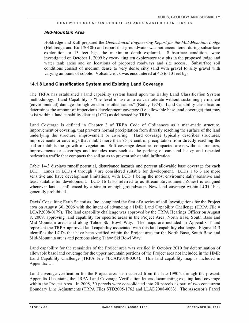
Mid-Mountain Area
Holdredge and Kull prepared the Geotechnical Engineering Report for the Mid-Mountain Lodge (Holdredge and Kull 2010b) and report that groundwater was not encountered during subsurface exploration to 13 feet bgs, the maximum depth explored. Subsurface conditions were investigated on October 1, 2009 by excavating ten exploratory test pits in the proposed lodge and water tank areas and on locations of proposed roadways and site access. Subsurface soil conditions consist of medium dense to very dense silty sand with gravel to silty gravel with varying amounts of cobble. Volcanic rock was encountered at 4.5 to 13 feet bgs.
14.1.8 Land Classification System and Existing Land Coverage
The TRPA has established a land capability system based upon the Bailey Land Classification System methodology. Land Capability is “the level of use an area can tolerate without sustaining permanent (environmental) damage through erosion or other causes” (Bailey 1974). Land Capability classification determines the amount of impervious development coverage (i.e. allowable base land coverage) that may exist within a land capability district (LCD) as delineated by TRPA.
Land Coverage is defined in Chapter 2 of TRPA Code of Ordinances as a man-made structure, improvement or covering, that prevents normal precipitation from directly reaching the surface of the land underlying the structure, improvement or covering. Hard coverage typically describes structures, improvements or coverings that inhibit more than 75 percent of precipitation from directly reaching the soil or inhibits the growth of vegetation. Soft coverage describes compacted areas without structures, improvements or coverings and includes uses such as the parking of cars and heavy and repeated pedestrian traffic that compacts the soil so as to prevent substantial infiltration
Table 14-3 displays runoff potential, disturbance hazards and percent allowable base coverage for each LCD. Lands in LCDs 4 through 7 are considered suitable for development. LCDs 1 to 3 are more sensitive and have development limitations, with LCD 1 being the most environmentally sensitive and least suitable for development. LCD 1b (also referred to as Stream Environment Zones) is assigned whenever land is influenced by a stream or high groundwater. New land coverage within LCD 1b is generally prohibited.
Davis2 Consulting Earth Scientists, Inc. completed the first of a series of soil investigations for the Project area on August 30, 2006 with the intent of advancing a HMR Land Capability Challenge (TRPA File # LCAP2008-0179). The land capability challenge was approved by the TRPA Hearings Officer on August 8, 2009, approving land capability for specific areas in the Project Area: North Base, South Base and Mid-Mountain areas and along Tahoe Ski Bowl Way. The maps are included in Appendix T and represent the TRPA-approved land capability associated with this land capability challenge. Figure 14-3 identifies the LCDs that have been verified within the Project area for the North Base, South Base and Mid-Mountain areas and portions along Tahoe Ski Bowl Way.
Land capability for the remainder of the Project area was verified in October 2010 for determination of allowable base land coverage for the upper mountain portions of the Project area not included in the HMR Land Capability Challenge (TRPA File #LCAP2010-0304). This land capability map is included in Appendix U.
Land coverage verification for the Project area has occurred from the late 1990’s through the present. Appendix U contains the TRPA Land Coverage Verification letters documenting existing land coverage within the Project Area. In 2008, 30 parcels were consolidated into 20 parcels as part of two concurrent Boundary Line Adjustments (TRPA Files STD2005-1762 and LLAD2008-0083). The Assessor’s Parcel
SOILS, GEOLOGY AND SEISMICITY H O M E W O O D M O U N T A I N R E S O R T S K I A R E A M A S T E R P L A N E I R / E I S
S E P T E M B E R 3 0 , 2 0 1 1 H A U G E B R U E C K A S S O C I A T E S P A G E 1 4 - 1 9
Numbers or APNs included in the land coverage verification letters are those recognized by TRPA at the time the verification was conducted and are not necessarily what Placer County recognized at the time. Many of the APNs referenced in the TRPA land coverage verifications, HMR Land Capability Challenge, and boundary line adjustments have since changed. Figure 3-4 represents the most recent APN information for the existing Project area, while Figure 14-3 shows the configuration of parcels before the sale of one parcel to the USFS and corresponds to Sheet C3a of the Civil Plans dated April 30, 2010. Appendix T presents figures for existing and proposed land coverage by APN as presented in HMR Land Capability Challenge and represent the preliminary land coverage calculations for the Project area that are discussed in the paragraphs below. Appendix V presents land coverage summaries associated with TRPA File # STD20051762 and LLAD2008-0083, the files on which the EIR/EIS land coverage analysis is based.
Table 14-3
Bailey System Basis of Capability for Lake Tahoe Basin Lands
Capability Level
Tolerance for Use
Slope
Runoff Potential
Runoff Potential
Disturbance Hazards
Allowable % Cover
7 Greatest 0-5% Slight Low to moderately low
Low hazard lands
30%
6 0-16% Slight Low to moderately low
Low hazard lands
30%
5 0-16% Slight Moderately high to high
Low hazard lands
25%
4 9-30% Moderate Low to moderately low
Moderate hazard lands
20%
3 9-30% Moderate Moderately high to high
Moderate hazard lands
5%
2 30-50% High Low to moderately low
High hazard lands
1%
1a Least 30+ High Moderately high to high
High hazard lands
1%
1b Poor natural drainage
High hazard lands
1%
1c Fragile flora and fauna
High hazard lands
1%
Source: Land Capability Classification of the Lake Tahoe Basin, California – Nevada, Bailey 1974
The total existing land coverage in the approximately 1,253-acre Project area is verified at 1,781,447 square feet. It is unclear if land coverage beneath the public rights-of-way (ROW) was included or excluded from the analysis completed for the boundary line adjustments for the Project area. HMR must coordinate with TRPA to determine if ROW has been considered and if not, formally apply to have coverage figures adjusted accordingly.
SOILS, GEOLOGY AND SEISMICITY H O M E W O O D M O U N T A I N R E S O R T S K I A R E A M A S T E R P L A N E I R / E I S
P A G E 1 4 - 2 0 H A U G E B R U E C K A S S O C I A T E S S E P T E M B E R 3 0 , 2 0 1 1
To present the most conservative land coverage calculations for existing conditions, the land coverage totals have been revised to reflect the exclusion of land beneath public ROWs located within the South Base area per TRPA Code of Ordinances Section 20.3.D(1)(b) by 20,110 square feet to equal 1,761,337 square feet. If this land coverage was previously excluded, then the existing land coverage analysis is conservative by 20,110 square feet. If this land coverage was not previously excluded, the existing land coverage analysis conforms to the TRPA requirements to exclude lands beneath public ROWs from allowable base land coverage determinations.
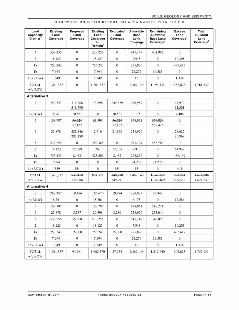
The TRPA Code of Ordinances provides methods for calculating allowable base land coverage in Section 20.3.D (2)(a). Allowable base land coverage is dependent on LCD coefficients, as outlined in Table 14-3 above. Table 14-4 compares the verified existing land coverage identified by the LCD in which the land coverage is located to the allowable base land coverage calculated for that LCD.
Total allowable base land coverage within the 1253-acre Project area equals 2,467,149 square feet. Verified existing land coverage is estimated at 1,781,447 square feet. Verified existing land coverage within LCDs 6, 5, 3, 4 and 1b conform to TRPA land coverage limits, while existing land coverage within LCDs 2 and 1a exceed allowable base land coverage by 10,205 and 477,417 square feet, respectively. LCDs 7 and 1c are not identified within the Project area.
Since 2006, approximately 19,000 linear feet of dirt access roads ranging from 7 to 18 feet in width have been treated and removed from within the Project area as part of sediment source control projects that removed and restored soft land coverage and disturbance associated with dirt access roads. The type of restoration, Tier 1, Tier 2 and Tier 3 are discussed in Chapter 15, Hydrology, Water Rights, Surface Water Quality and Groundwater. Land coverage that is removed (i.e. soft coverage associated with compacted roadway surface; road widths range between 7 and 18 feet – personal communication TRPA Staff September 28, 2010) can be banked as land coverage for use in areas of higher capability LCDs or relocated within the project area. Disturbance restoration (i.e., cut and fill slopes) may possibly be banked as restoration credit per TRPA Code of Ordinance Section 20.4.C. The recently removed land coverage and disturbance have not been verified and banked to date. The land coverage is considered to be still in existence until banking applications are verified and approved by TRPA staff. Therefore, the land coverage is treated as existing land coverage in the land coverage calculations detailed in Table 14-4. Figure 14-4 illustrates the locations of the removed and restored land coverage and disturbance. Banking applications must be initiated by the Project Applicant.
SOILS, GEOLOGY AND SEISMICITY H O M E W O O D M O U N T A I N R E S O R T S K I A R E A M A S T E R P L A N E I R / E I S
S E P T E M B E R 3 0 , 2 0 1 1 H A U G E B R U E C K A S S O C I A T E S P A G E 1 4 - 2 1
Table 14-4
Project Area Land Capability and Existing Land Coverage Determinations
Source: TRPA land capability challenge documents – August 8, 2009; HMR Master Plan Project Coverage Calculations Table May 20, 2010 and HBA 2010
Note: 1 TRPA Code of Ordinances Section 20.3.D(2)(2)(ii) outlines the methodology for calculating allowable and maximum allowable
base land coverage. TRPA Code Section 20.3.D(1)(b) excludes land beneath Public Right of Ways (ROWs) from inclusion in the Project area of the calculations of allowable base land coverage.
2 Banked coverage associated with removal of “Lombard Street” per TRPA File #970662 to APN 097-210-01. This banked land coverage was distributed as follows: 80% attributed to APN 97-060-12, 15% attributed to APN 97-060-10 and 5% attributed to APN 97-050-22. This banked land coverage is available for relocation within the Project area and is not included in the totals.
3From page 20-25 of the TRPA Code of Ordinances: Excess Land Coverage is defined as the existing amount of land coverage, less the total of the following: the maximum allowable amount of base coverage; the amount of coverage approved by transfer; and the amount of coverage previously mitigated. Excess Land Coverage (% sf) = Existing Land Coverage (% sf) – (Maximum coverage (% sf) + Transferred Coverage (% sf) + Previously Mitigated Coverage (% sf)).
4. Remaining Base Land Coverage is defined as Allowable Base Land Coverage minus Existing Improvements/Land Coverage
SOILS, GEOLOGY AND SEISMICITY H O M E W O O D M O U N T A I N R E S O R T S K I A R E A M A S T E R P L A N E I R / E I S
P A G E 1 4 - 2 2 H A U G E B R U E C K A S S O C I A T E S S E P T E M B E R 3 0 , 2 0 1 1
Figure 14-3. Land Capability Challenge Area Exhibit
SOILS, GEOLOGY AND SEISMICITY H O M E W O O D M O U N T A I N R E S O R T S K I A R E A M A S T E R P L A N E I R / E I S
S E P T E M B E R 3 0 , 2 0 1 1 H A U G E B R U E C K A S S O C I A T E S P A G E 1 4 - 2 3
Figure 14-4. Sediment Source Control Projects for Land Coverage Reductions, 2006-2009
SOILS, GEOLOGY AND SEISMICITY H O M E W O O D M O U N T A I N R E S O R T S K I A R E A M A S T E R P L A N E I R / E I S
P A G E 1 4 - 2 4 H A U G E B R U E C K A S S O C I A T E S S E P T E M B E R 3 0 , 2 0 1 1
The HMR CWE analysis and watershed thresholds of concern (TOCs) completed in compliance with the TRPA Ski Area Master Plan Guidelines are detailed in Chapter 15, Hydrology, Surface Water Quality, Water Rights and Groundwater in Impact HYDRO-1.
14.2 REGULATORY SETTING
TRPA, Placer County and the State of California enforce regulations for the protection of soils and earth resources of the Project area. The following subsections discuss the regulatory framework pertaining to the Project.
14.2.1 Tahoe Regional Planning Agency
TRPA adopted development restrictions limiting land coverage in Project areas to a range of impervious land coverage coefficients. Chapter 2 of the TRPA Code of Ordinances defines land coverage. Land coverage limits are set forth in Chapter 20 of the TRPA Code of Ordinances, which define allowable base land coverage according to LCDs. Section 20.3 of the Code outlines the process for calculating allowable base land coverage as determined by land capability. Section 20.5 of the Code outlines the regulations and requirements for the Excess Land Coverage Mitigation Program. Section 20.5.C outlines the regulations and requirements for the relocation of existing land coverage on the same parcel or Project area. Removed and relocated coverage must be restored pursuant to Subsection 20.4.C. Section 20.3.B outlines the necessary findings for the transfer of land coverage. Best Management Practices (BMPs) requirements, natural hazard standards, and design standards are presented in Code of Ordinance Chapters 25, 28 and 30, respectively.
Community Enhancement Program
The Project is a participant in the TRPA Community Enhancement Program (CEP). As stated in the February 5, 2008 Resolution 2008-11 Exhibit 7 Memorandum, the TRPA document that outlines the CEP requirements as they apply to the Project, TRPA requires that HMR specify the percentage of land coverage reduction proposed for the overall Project. The CEP requires a substantial land coverage reduction and states that the increase in density and height should result in an overall reduction in land coverage within the Project area.
The Resolution states that the uses of a building envelope that would allow a building to stair step up the slope to a maximum of 50 feet at the highest point of the envelope or slope may be appropriate for the Project area. This approach may limit the amount of grading and cut required for building foundations, which would provide an added environmental benefit. TRPA requires the verification of the existing land coverage, land capability and units of use along with assurances that proposed building locations and proposed land coverage transfers will not impact sensitive lands.
Grading Requirements
There are grading standards set forth in Chapters 20 and 64 of the TRPA Code of Ordinances. Limitations include no excavation, filling, or clearing of vegetation or other disturbance of the soil between October 15 and May 1 of each year, unless approval is granted by TRPA. Grading and construction schedules are established in Chapter 62 of the Code of Ordinances. A grading plan is required by TRPA prior to project approval and project construction.
SOILS, GEOLOGY AND SEISMICITY H O M E W O O D M O U N T A I N R E S O R T S K I A R E A M A S T E R P L A N E I R / E I S
S E P T E M B E R 3 0 , 2 0 1 1 H A U G E B R U E C K A S S O C I A T E S P A G E 1 4 - 2 5
Groundwater Regulations
According to the TRPA Code, Chapter 64, groundwater impacts are considered significant if implementation of the project results in the interception or interference of groundwater by:
• Altering the direction of groundwater; • Altering the rate of flow of groundwater; • Intercepting groundwater; • Adding or withdrawing groundwater; or • Raising or lowering the water table.
TRPA Code, Chapter 64, Section 64.7.B prohibits excavations in excess of five feet in depth or when there exists a reasonable possibility of interference or interception of a water table unless the following findings can be made:
“(1) A soils/hydrologic report prepared by a qualified professional, whose proposed content and methodology has been reviewed and approved in advance by TRPA, demonstrates that no interference or interception of groundwater will occur as a result of the excavation; and
(2) The excavation is designed such that no damage occurs to mature trees, except where tree removal is allowed pursuant to Subsection 65.2.E, including root systems, and hydrologic conditions of the soil. To ensure the protection of vegetation necessary for screening, a special vegetation protection report shall be prepared by a qualified professional identifying measures necessary to ensure damage will not occur as a result of the excavation; and
(3) Excavated material is disposed of pursuant to Section 64.5 and the Project area’s natural topography is maintained pursuant to Subparagraph 30.5.A(1); or if groundwater interception or interference will occur as described in the soils/hydrologic report, the excavation can be made as an exception pursuant to Subparagraph 64.7.A(2) and measures are included in the project to maintain groundwater flows to avoid adverse impacts to SEZ vegetation, if any would be affected, and to prevent any groundwater or subsurface flow from leaving the Project area as surface flow.”
As part of the permitting process for the chosen alternative and final design plans, HMR is required to submit a soils/hydrologic report that includes a brief summary of the geologic, soil, and hydrologic conditions expected to be encountered within the chosen alternative Project area. Qualifications of the personnel conducting the soil/hydrologic investigation will be included in the report. The report must specify if the field exploration was conducted by backhoe excavation test pits or drilled boring, and the depths to which the samples were taken. Methods must comply with TRPA requirements to reveal information to 125% of the excavation depth. The boring logs must reveal the vertical sequence of soil textures, percent rock fragment, soil colors, and depths associated with the contact boundaries of these features.
The Second Revised Soils Hydrologic Scoping and Final Report was submitted to TRPA on October 7,, 2010 for review and approval of excavations necessary for building foundations and underground parking structures in the North and South Base areas and for building foundations at the Mid-Mountain area, but has not been fully reviewed or approved at this time.
Based on groundwater monitoring data and site conditions, groundwater is anticipated to be intercepted during construction and long-term operations in the North and South Base areas as a result of excavations. To reduce potential impacts from excavations at the North and South Base
SOILS, GEOLOGY AND SEISMICITY H O M E W O O D M O U N T A I N R E S O R T S K I A R E A M A S T E R P L A N E I R / E I S
P A G E 1 4 - 2 6 H A U G E B R U E C K A S S O C I A T E S S E P T E M B E R 3 0 , 2 0 1 1
areas, the hotel foundation footings were redesigned to avoid groundwater interception and underground parking structures were designed to minimize groundwater interception. Remaining groundwater that is intercepted by the underground parking structures will require an amendment to TRPA Code Chapter 64, as described in Chapter 3, Description of Proposed Project and Alternatives.
14.2.2 State of California
California Regional Water Quality Control Board – Lahontan Region
Section 402 of the Clean Water Act (CWA) is directly relevant to earthwork and grading in the Project area and establishes the National Pollutant Discharge Elimination System Program (NPDES) program that the California Regional Water Quality Control Board – Lahontan Region (Lahontan) implements in Lake Tahoe. Projects with construction activities disturbing greater than one acre must apply for coverage under Board Order No R6T-2005-0007, prepare a Notice of Intent (NOI) and implement a Stormwater Pollution Prevention Plan (SWPPP). BMPs must be installed and maintained to avoid adverse impacts to receiving water quality as defined by Chapter 5 of the Lahontan Basin Plan. Upon completion of the Project, HMR must submit a Notice of Termination (NOT) to Lahontan to indicate that construction is completed. Further information regarding Lahontan’s requirements for NPDES permitting is set forth in Chapter 15 (Hydrology, Water Rights, Surface Water Quality and Groundwater).
Section 5.4 of the Basin Plan outlines land capability and coverage limitations and section 5.7 outlines protections for SEZ, low capability LCDs, and floodplains.
California Building Codes
Pursuant to authority of Government Code Section 50022.1 et seq., the State of California adopted the following building codes to maintain a standard of public safety.
A. International Building Code 2006 edition as adopted in The California Building Standards Code (The 2007 California Building Code), which adopts those standards with state agency modifications within the scope of their authority.
B. National Electrical Code 2005 edition as adopted in The California Building Standards Code (The 2007 California Electric Code), which adopts those standards with state agency modifications within the scope of their authority, published by the National Fire Protection Association, California Administrative Code, Provisions for the National Electrical Code, 2007 Edition, published by International Code Council (ICC).
C. Uniform Plumbing Code 2006 edition as adopted in The California Building Standards Code, including appendices (The 2007 California Plumbing Code), which adopts those standards with state agency modifications within the scope of their authority, published by the International Association of Plumbing and Mechanical Officials.
D. Uniform Mechanical Code 2006 edition as adopted in The California Building Standards Code, including appendices (The 2007 California Mechanical Code), which adopts those standards with state agency modifications within the scope of their authority, published by the International Association of Plumbing and Mechanical Officials (IAPMO).
SOILS, GEOLOGY AND SEISMICITY H O M E W O O D M O U N T A I N R E S O R T S K I A R E A M A S T E R P L A N E I R / E I S
S E P T E M B E R 3 0 , 2 0 1 1 H A U G E B R U E C K A S S O C I A T E S P A G E 1 4 - 2 7
E. International Existing Building Code 2006 as adopted in The California Building Standards Code (The 2007 California Existing Building Code), which adopts those standards with state agency modifications within the scope of their authority and as limited by Health and Safety Code 19160 et seq., published by ICC.
F. International Fire Code 2006 edition including Appendices’ as adopted in The California Building Standards Code (The 2007 California Fire Code), which adopts those standards with state agency modifications within the scope of their authority, published by ICC.
G. International Property Maintenance Code 2006 Edition, published by ICC, as modified by The California Health and Safety Code, Title 25 of the California Code of Regulations, and as further modified in Article 15.56.
H. The following codes and standards are adopted as reference documents and may be used by the chief building official in accordance with California Building Code Sections 104.10 and 104.11 in a case by case review process: Uniform Building Code 1997 edition, Uniform Swimming Pool Code, Spa & Hot Tub Code, published by IAPMO; published supplements to the International Codes; The International Residential Code; The 2006 International Fuel Gas Code; The Urban Wildland Interface Code, published by the International Fire Code Institute; The Uniform Sign Code, published by ICBO; IBC Appendix Chapters; National Fire Protection Association Standards; the Uniform Solar Energy Code, as published by IAPMO; American National Standard, published by American National Standards Institute, Inc.; Masonry Fireplaces, Masonry Institute; and other Nationally recognized Standards. (Ord. 5200-B (part), 2002: Ord. 4959-B (part), 1999: prior code § 4.1)
I. California Health and Safety Code § 19100 et seq
Alquist-Priolo Earthquake Fault Zone Act
The Alquist-Priolo Earthquake Fault Zoning Act (PRC Section 2621-2630) intends to reduce the risk to life and property from surface fault rupture during earthquakes by regulating construction in active fault corridors and prohibiting the location of most types of structures intended for human occupancy across the traces of active faults. The act defines criteria for identifying active faults, giving legal support to terms such as active and inactive and establishes a process for reviewing building proposals in Earthquake Fault Zones.
Under the Alquist-Priolo Act, faults are zoned and construction along or across these zones is strictly regulated if they are “sufficiently active” and “well-defined.” A fault is considered sufficiently active if one or more of its segments or strands shows evidence of surface displacement during Holocene time (defined for purposes of the act as within the last 11,000 years). A fault is considered well defined if its trace can be clearly identified by a trained geologist at the ground surface or in the shallow subsurface, using standard professional techniques, criteria, and judgment (Hart and Bryant 1997). There are no faults identified or mapped as active within the Project area as defined by the act.
Seismic Hazards Mapping Act
The intention of The Seismic Hazards Mapping Act of 1990 (PRC Sec. 2690– 2699.6) is to reduce damage resulting from earthquakes. The Alquist-Priolo Act addresses surface fault rupture and the Seismic Hazards Mapping Act addresses other earthquake-related hazards, including strong ground shaking, liquefaction, and seismically induced landslides. The act’s
SOILS, GEOLOGY AND SEISMICITY H O M E W O O D M O U N T A I N R E S O R T S K I A R E A M A S T E R P L A N E I R / E I S
P A G E 1 4 - 2 8 H A U G E B R U E C K A S S O C I A T E S S E P T E M B E R 3 0 , 2 0 1 1
provisions are similar in concept to those of the Alquist-Priolo Act: the State is charged with identifying and mapping areas at risk of strong ground shaking, liquefaction, landslides, and other corollary hazards, and cities and counties are required to regulate development within mapped Seismic Hazard Zones.
Under the Seismic Hazards Mapping Act, permit review is the primary mechanism for local regulation of development. Specifically, cities and counties are prohibited from issuing development permits for projects in Seismic Hazard Zones until appropriate site- specific geologic or geotechnical investigations have been carried out and measures to reduce potential damage have been incorporated into the development plans.
14.2.3 Placer County
General Plan
Placer County General Plan (1994) policies listed under Goal 8.A for seismic and geological hazards apply to the Project.
Goal 8.A. To minimize the loss of life, injury, and property damage due to seismic and geological hazards.
8.A.1. The County shall require the preparation of a soils engineering and geologic-seismic analysis prior to permitting development in areas prone to geological or seismic hazards (i.e., groundshaking, landslides, liquefaction, critically expansive soils, avalanche).
8.A.2. The County shall require submission of a preliminary soils report, prepared by a registered civil engineer and based upon adequate test borings, for every major subdivision and for each individual lot where critically expansive soils have been identified or are expected to exist.
8.A.3. The County shall prohibit the placement of habitable structures or individual sewage disposal systems on or in critically expansive soils unless suitable mitigation measures are incorporated to prevent the potential risks of these conditions.
8.A.4. The County shall ensure that areas of slope instability are adequately investigated and that any development in these areas incorporates appropriate design provisions to prevent landsliding.
8.A.5. In landslide hazard areas, the County shall prohibit avoidable alteration of land in a manner that could increase the hazard, including concentration of water through drainage, irrigation, or septic systems; removal of vegetative cover; and steepening of slopes and undercutting the bases of slopes.
8.A.6. The County shall require the preparation of drainage plans for development in hillside areas that direct runoff and drainage away from unstable slopes.
8.A.7. In areas subject to severe ground shaking, the County shall require that new structures intended for human occupancy be designed and constructed to minimize risk to the safety of occupants.
8.A.8. County shall continue to support scientific geologic investigations which refine, enlarge, and improve the body of knowledge on active fault zones, unstable areas, severe groundshaking, avalanche potential, and other hazardous conditions in Placer County.
SOILS, GEOLOGY AND SEISMICITY H O M E W O O D M O U N T A I N R E S O R T S K I A R E A M A S T E R P L A N E I R / E I S
S E P T E M B E R 3 0 , 2 0 1 1 H A U G E B R U E C K A S S O C I A T E S P A G E 1 4 - 2 9
8.A.9. The County shall require that the location and/or design of any new buildings, facilities, or other development in areas subject to earthquake activity minimize exposure to danger from fault rupture or creep.
8.A.10. The County shall require that new structures permitted in areas of high liquefaction potential be sited, designed, and constructed to minimize the dangers from damage due to earthquake-induced liquefaction
8.A.11. The County shall limit development in areas of steep or unstable slopes to minimize hazards caused by landslides or liquefaction.
West Shore Area General Plan
The West Shore Area General Plan, adopted by Placer County in October 1998, includes a Safety Element that addresses seismic, geologic, flood, avalanche, and wildfire hazards. Avalanches and wildfire hazards are addressed in Chapter 17, Hazardous Waste and Public Safety and flooding hazards are addressed in Chapter 15, Hydrology, Water Rights, Surface Water Quality and Groundwater.
Placer County Building and Land Development Ordinances
Placer County requires the preparation of a geotechnical and soils analysis for project permitting in areas prone to geologic or seismic hazards (see Article 15.48 of Chapter 15 of the Placer County Code). Kleinfelder Inc. prepared the Geologic Hazards and Preliminary Geotechnical Evaluation Homewood Mountain Resort in November 1, 2007 and followed the Placer County Community Development Resource Agency guidelines for a preliminary geotechnical report. The purpose of the report is to identify and assess the potential geologic hazards present geotechnical considerations for the Project area. Follow up site-specific geotechnical evaluations were completed by Holdrege and Kull for the Master Plan Phase 1 North Base and the Mid-Mountain areas. The relevant recommendations from the reports are included in the Environmental Impacts and Recommended Mitigation section below, and included as standard project-level mitigation measures.
Placer County adopted the California Building Codes on January 1, 201108. The adopted building and construction codes are contained in Placer County Code Article 15.04 of Chapter 15. Article 15.48 of Chapter 15 of the Placer County Code outlines permitting requirements to comply with the Grading, Erosion and Sediment Control Ordinance along with special restrictions and exemptions for the Lake Tahoe Basin. As a lead agency under CEQA, Placer County must comply with the Lahontan WDRs and Lahontan Board Order No. R6T-2005-007 for construction activities within the Lake Tahoe Hydrologic Unit. The Project Applicant complies with permitting requirements through the development of a project-specific SWPPP that is subject to approval by Lahontan.
Lahontan previously established WDRs for the Project area under Board Order No. 6-79-51, which was adopted September 19, 1979, and Board Order No. 6-88-174, which was adopted November 9, 1988. The current Board Order No. 6-95-86 updated WDRs to be consistent with requirements placed on other ski resorts within the Region and established specific compliance dates, which extend those in Board Order No 6-88-174.
Placer County Land Development Manual, Stormwater Management Manual, and General Construction Specifications (Placer County 1994) contain information on grading, subbases and
SOILS, GEOLOGY AND SEISMICITY H O M E W O O D M O U N T A I N R E S O R T S K I A R E A M A S T E R P L A N E I R / E I S
P A G E 1 4 - 3 0 H A U G E B R U E C K A S S O C I A T E S S E P T E M B E R 3 0 , 2 0 1 1
bases, surfacings and pavements, structures, drainage facilities, right-of-ways (ROW) and traffic control facilities, and materials. Construction specifications developed for the Project within the State Route 89 ROW will comply with applicable Caltrans standards. For consistency, improvements in the Placer County ROW will also comply with Caltrans standards.
Placer County Grading, Erosion, and Sediment Control Ordinance
The Placer County Board of Supervisors adopted the following relevant regulations pertaining to grading and related runoff in Placer County,
15.48.020 Purpose. The ordinance codified in this article is enacted for the purpose of regulating grading on property within the unincorporated area of Placer County to safeguard life, limb, health, property and public welfare; to avoid pollution of watercourses with hazardous materials, nutrients, sediments, or other earthen materials generated on or caused by surface runoff on or across the permit area; and to ensure that the intended use of a graded site is consistent with the Placer County general plan, any specific plans adopted thereto and applicable Placer County ordinances including the zoning ordinance, flood damage prevention ordinance, (Article 15.52) environmental review ordinance (Chapter 18 Placer County Code) and applicable chapters of the California Building Code. In the event of conflict between applicable chapters and this article, the most restrictive shall prevail. (Ord. 5056-B (part), 2000)
15.48.040 Grading. No person shall do or permit to be done any grading in such a manner that quantities of dirt, soil, rock, debris or other material substantially in excess of natural levels are washed, eroded or otherwise moved from the site, except as specifically provided for by a permit. In no event shall grading activities cause or contribute to the violation of provisions of any applicable NPDES stormwater discharge permit. (Ord. 5407-B § 2, 2006: Ord. 5056-B (part), 2000)
15.48.050 Water obstruction. 15.48.090 Levee work. No person shall excavate or remove any material from or otherwise alter any levee required for river, creek, bay, or local drainage control channel, without prior approval of the local governmental agency responsible for the maintenance of the levee. (Ord. 5056-B (part), 2000)
15.48.100 Construction in public rights-of-way. No person shall perform any grading work within the right-of-way of a public road or street, or within a public easement, without prior written approval of the agency director. (Ord. 5407-B § 6, 2006: Ord. 5056-B (part), 2000)
15.48.110 Hazards. If the community development resource agency director determines that any grading on private or public property constitutes a hazard to public safety; endangers property; adversely affects the safety, use or stability of adjacent property, an overhead or underground utility, or a public way, watercourse or drainage channel; or could adversely affect the water quality of any water bodies or watercourses, the director may issue a stop work notice to the owner of the property upon which the condition is located, or other person or agent in control of such property. Upon receipt of such stop work notice, the recipient shall, within the period specified therein, stop all work, obtain a grading permit and conform to the conditions of such permit. The community development resource agency may require the submission of plans or soil or geological reports, detailed construction recommendations, drainage study or other engineering data prior to and in connection with any corrective or proposed work or activity. (Ord. 5407-B § 7, 2006: Ord. 5373-B (part), 2005; Ord. 5056-B (part), 2000)
15.48.120 Tahoe Basin area special restrictions and exemptions.
SOILS, GEOLOGY AND SEISMICITY H O M E W O O D M O U N T A I N R E S O R T S K I A R E A M A S T E R P L A N E I R / E I S
S E P T E M B E R 3 0 , 2 0 1 1 H A U G E B R U E C K A S S O C I A T E S P A G E 1 4 - 3 1
A. Provisions of this section apply to the unincorporated area of Placer County within that area defined as “TRPA region” in the Tahoe Regional Planning Agency Compact. This area is the Tahoe Basin and that additional and adjacent part of the county of Placer outside of the Tahoe Basin in the state of California which lies southward and eastward of a line starting at the intersection of the basin crestline and the north boundary of Section 1, thence west to the northwest corner of Section 3, thence south to the intersection of the basin crestline and the west boundary of Section 10; all sections referring to township 15 north, range 16 east, M.D.B. and M.
B. Grading and soil disturbance shall be prohibited during the period from October 15th through May 1st unless otherwise approved, in writing, by the agency director and by the Tahoe Regional Planning Agency and Lahontan Regional Water Quality Control Board. Complete winterization of the site is required by October 15th, if work is not complete and permanent revegetation is not established.
C. All work shall be in conformity with any grading restriction required by other federal, state, or local agencies.
D. A permit for grading on residential property issued by the Tahoe Regional Planning Agency will be evidence of conformity to provisions of this section. All other grading in the region, unless otherwise exempt as provided herein, is subject to review and approval by the community development resource agency.
E. Areas of the site not approved for grading, vegetation removal, or construction shall be fenced or otherwise marked to limit access. These fences shall be inspected, maintained, and repaired as necessary.
F. Prior to initiation of grading or construction-related activity, temporary erosion control measures shall be installed to prevent transport of earthen materials and other wastes off of the site.
G. All other provisions of this article shall apply, but a permit shall not be required if the work complies with all the following conditions:
1. The excavation does not exceed four feet in vertical depth at its deepest point measured from the original ground surface, does not exceed two hundred (200) square feet in area, and does not exceed three cubic yards per site;
2. The fill does not exceed three feet in vertical depth at its deepest point measured from the original ground surface, the fill material does not cover more than two hundred (200) square feet, and does not exceed three cubic yards per site;
3. The clearing of vegetation does not exceed one thousand (1,000) square feet in area. (Ord. 5407-B § 8, 2006: Ord. 5373-B (part), 2005; Ord. 5056-B (part), 2000) No person shall do or permit to be done any grading which may obstruct, impede or interfere with the natural flow of stormwaters, in such manner as to cause flooding where it would not otherwise occur, aggravate any existing flooding condition or cause accelerated erosion. This section applies whether such waters are unconfined upon the surface of the land or confined within land depressions or natural drainage ways, unimproved channels or watercourses, or improved ditches, channels or conduits. (Ord. 5056-B (part), 2000)
SOILS, GEOLOGY AND SEISMICITY H O M E W O O D M O U N T A I N R E S O R T S K I A R E A M A S T E R P L A N E I R / E I S
P A G E 1 4 - 3 2 H A U G E B R U E C K A S S O C I A T E S S E P T E M B E R 3 0 , 2 0 1 1
15.48.360 Geotechnical investigation required. A soil or geologic investigation report shall accompany the application in any of the following circumstances when required by the agency director:
A. When the proposed grading includes a cut or fill exceeding ten (10) feet in depth at any point; however, for vehicular ways, a soil investigation shall not be required unless the grading includes a proposed cut or fill that exceeds ten (10) feet in depth and the slope of the natural ground exceeds thirty (30) percent;
B. When highly expansive soils are present;
C. In areas of known or suspected geological hazards, including landslide hazards and hazards of ground failure stemming from seismically induced ground shaking. (Ord. 5407-B § 13, 2006: Ord. 5056-B (part), 2000)
D. Recommendations regarding surface and subsurface drainage and erosion control; Recommendations for mitigation of geologic hazards. (Ord. 5056-B (part), 2000)
15.48.400 Final report. Upon completion of rough grading work, in the event a complete record of the work is desired or necessary, the community development resource agency may require a final geotechnical report that includes, but is not necessarily limited to the following:
A. A complete record of all field and laboratory tests including location and elevation of all field tests;
B. A professional opinion regarding slope stability, soil bearing capacity, and any other pertinent information;
C. Recommendations regarding foundation design, including soil bearing potential and building restrictions or setbacks from the top or toe of slopes; and
D. A declaration by the geotechnical engineer, civil engineer or engineering geologist in the format required by the community development resource agency that all work was done in substantial conformance with the recommendations contained in the soil or geologic investigation reports as approved and in accordance with the approved plans and specification. (Ord. 5407-B (part), 2006; Ord. 5373-B (part), 2005; Ord. 5056-B (part), 2000)
15.48.560 Setbacks—General. Unless otherwise recommended in a soil or geologic investigation report, Appendix 33 of the latest county adopted version of the Uniform Building Code shall be used for establishing setbacks for property boundaries, buildings and structures other than fences and retaining walls. (Ord. 5407-B § 15, 2006: Ord. 5056-B (part), 2000)
15.48.570 Drainage—General. Any drainage structure(s) or device(s) carrying surface water runoff required by this article shall be designed and constructed in accordance with standards herein, the current Placer County flood control and water conservation district stormwater management manual and criteria authorized by the agency director. (Ord. 5407-B § 16, 2006: Ord. 5056-B (part), 2000)
SOILS, GEOLOGY AND SEISMICITY H O M E W O O D M O U N T A I N R E S O R T S K I A R E A M A S T E R P L A N E I R / E I S
S E P T E M B E R 3 0 , 2 0 1 1 H A U G E B R U E C K A S S O C I A T E S P A G E 1 4 - 3 3
15.48.580 Drainage discharge requirements. All drainage facilities shall be designed and engineered to carry surface and subsurface waters to the nearest adequate street, storm drain, natural watercourse, or other juncture. (Ord. 5373-B (part), 2005; Ord. 5056-B (part), 2000)
15.48.590 Drainage—Water accumulation. All areas shall be graded and drained so that drainage will not cause erosion or endanger the stability of any cut or fill slope or any building or structure. (Ord. 5056-B (part), 2000)
15.48.600 Drainage protection of adjoining property. When surface drainage is discharged onto any adjoining property, it shall be discharged in such a manner that it will not cause erosion or endanger any cut or fill slope or any building or structure. (Ord. 5056-B (part), 2000)
15.48.610 Terrace drainage. Terraces at least eight feet in width shall be established at not more than twenty-five (25) feet in height intervals for all cut and fill slopes exceeding thirty (30) feet in height. Where only one terrace is required, it shall be at approximately mid-height. Suitable access shall be provided to permit proper cleaning and maintenance of terraces and terrace drains. Swales or ditches on terraces shall have a minimum depth of one foot, a minimum longitudinal grade of four percent, a maximum longitudinal grade of twelve (12) percent. Down-drains or drainage outlets shall be provided at approximately three hundred (300) foot intervals along the drainage terrace. Down-drains and drainage outlets shall be of approved materials and of adequate capacity to convey the intercepted waters to the point of disposal. If the drainage discharges onto natural ground, adequate erosion protection shall be provided. (Ord. 5056-B (part), 2000)
15.48.620 Subsurface drainage. Cut and fill slopes shall be provided with surface and/or subsurface drainage as necessary for stability. (Ord. 5056-B (part), 2000)
15.48.630 Erosion and sediment control. The following shall apply to the control of erosion and sediment from grading operations:
A. Grading plans shall be designed with long-term erosion and sediment control as a primary consideration. Erosion prevention and source control are to be emphasized over sediment controls and treatment.
B. Grading operations shall provide erosion and sediment control measures, except upon a clear demonstration, to the satisfaction of the community development resource agency that at no stage of the work will there be any substantial risk of increased sediment discharge from the site. Temporary mulch, revegetation, or other stabilization methods shall be applied to areas where permanent revegetation or landscaping cannot be immediately implemented. Unless otherwise exempted in this article, grading activity must be scheduled to ensure completion or winterization by October 15th of each year.
C. Grading activity shall be conducted such that the smallest practicable area of erodible land is exposed at any one time during grading operations and the time of exposure is minimized. Land disturbance shall be limited to the minimum area necessary for construction.
D. Natural features, including vegetation, terrain, watercourses and similar resources shall be protected and preserved wherever possible. Units of grading shall be dearly defined and marked to prevent damage by construction equipment.
SOILS, GEOLOGY AND SEISMICITY H O M E W O O D M O U N T A I N R E S O R T S K I A R E A M A S T E R P L A N E I R / E I S
P A G E 1 4 - 3 4 H A U G E B R U E C K A S S O C I A T E S S E P T E M B E R 3 0 , 2 0 1 1
E. Permanent vegetation and structures for erosion and sediment control shall be installed as soon as possible.
F. Adequate provision shall be made for effective maintenance of temporary and permanent erosion and sediment control structures and vegetation. Sediment and other construction-related wastes shall be retained and properly managed on the site or properly disposed of off-site.
G. No topsoil shall be removed from the site unless otherwise directed or approved by the community development resource agency. Topsoil overburden shall be stockpiled and redistributed where appropriate within the graded area after rough grading to provide a suitable base for seeding and planting. Runoff from the stockpiled area shall be controlled to prevent erosion and resultant sedimentation of receiving water.
H. Runoff shall not be discharged from the site in quantities or at velocities substantially above those which occurred before grading except into drainage facilities, whose design has been specifically approved by the community development resource agency.
I. The permittee shall take reasonable precautions to ensure that vehicles do not track or spill earth materials into public streets and shall immediately remove such materials if this occurs.
J. All cut and fill slopes shall be adequately stabilized to prevent erosion and failure through temporary and permanent means.
K. Control measures shall be employed to prevent transport of dust off the project site or into any drainage course or water body. (Ord. 5407-B § 17, 2006: Ord. 5373-B (part), 2005; Ord. 5056-B (part), 2000)
15.48.650 Erosion and sediment control plans. Erosion and sediment control plans prepared pursuant to this article shall comply with all of the following:
A. The erosion and sediment control plan need not be a separate sheet if all facilities and measures can be shown on the grading sheets without obscuring the clarity of either the grading plan or the erosion and sediment control plan.
B. An erosion and sediment control plan shall be required whenever:
1. The graded portion of the site includes more than ten thousand (10,000) square feet of area having a slope greater than ten (10) percent;
2. Clearing and grubbing of areas of one acre or more regardless of slope;
3. There is a significant risk that more than two thousand five hundred (2,500) square feet will be unprotected or inadequately protected from erosion during any portion of the rainy season;
4. Grading will occur within fifty (50) feet of any watercourse;
5. The community development resource agency determines that the grading will or may pose a significant erosion, or sediment discharge hazard for any reason; or
SOILS, GEOLOGY AND SEISMICITY H O M E W O O D M O U N T A I N R E S O R T S K I A R E A M A S T E R P L A N E I R / E I S
S E P T E M B E R 3 0 , 2 0 1 1 H A U G E B R U E C K A S S O C I A T E S P A G E 1 4 - 3 5
6. The site is located within the Tahoe Basin.
C. Except as provided in Section 15.48.120 of this article, sediment and erosion control measures must be in place or be capable of being placed within twenty-four (24) hours, in the opinion of the agency director, by October 15th. The agency director may require suspension of any and all grading activities between October 15 and May 1 without prior notice.
D. The applicant shall submit with the erosion and sediment control plans a detailed cost estimate covering this work.
E. Erosion and sediment control plans shall include an effective revegetation program to stabilize all disturbed areas, which will not be otherwise protected. All such areas where grading has been completed between April 1 and October 15 shall be planted by November 1st. Graded areas completed at other times of the year shall be planted within fifteen (15) days. If revegetation is infeasible or cannot be expected to stabilize an erodible area with assurance during any part of the rainy season and the unstable area exceeds two thousand five hundred (2,500) square feet, additional erosion and sediment control measures or irrigation of planted slopes may be required as appropriate to prevent increased sediment discharge.
F. Erosion and sediment control plans shall be designed to prevent increased discharge of sediment at all stages of grading and development from initial disturbance of the ground to project completion. Every feasible effort shall be made to ensure that site stabilization is permanent. Plans shall indicate the implementation period and the stage of construction where applicable.
G. Erosion and sediment control plans shall comply with the recommendations of the responsible civil engineer, geotechnical engineer, engineering geologist, or landscape architect involved in preparation of the grading plans.
H. The structural and hydraulic adequacy of all stormwater containment or conveyance facilities shown on the erosion and sediment control plans shall be verified by a civil engineer, and he or she shall so attest on the plans. Sufficient calculations and supporting material to demonstrate such adequacy shall accompany the plans when submitted.
I. Erosion and sediment control plans shall be designed to meet anticipated field conditions.
J. Erosion and sediment control plans shall provide for inspection and repair of all erosion and sediment control facilities at the close of each working day during the rainy season and for specific sediment cleanout and vegetation maintenance criteria.
K. Erosion and sediment control plans shall comply with any and all standards and specifications adopted herein for the control of erosion and sedimentation on grading sites. These standards and specifications shall be in general compliance with the current Erosion and Sediment Control Guidelines for Developing Areas of the Sierras, published by the High Sierra Resource Conservation District. (Ord. 5407-B § 19, 2006: Ord. 5373-B (part), 2005; Ord. 5056-B (part), 2000)
15.48.660 Vehicular ways—General.. Vehicular ways shall conform to the grading requirements of this article. (Ord. 5056-B (part), 2000)
SOILS, GEOLOGY AND SEISMICITY H O M E W O O D M O U N T A I N R E S O R T S K I A R E A M A S T E R P L A N E I R / E I S
P A G E 1 4 - 3 6 H A U G E B R U E C K A S S O C I A T E S S E P T E M B E R 3 0 , 2 0 1 1
15.48.670 Vehicular ways—Drainage. Vehicular ways shall be graded and drained in such a manner that will not allow erosion or endanger the stability of any adjacent slope. Surface discharge onto adjoining property shall be controlled in such a manner that it does not cause erosion or endanger existing improvements. Bridges and culverts installed in watercourses may be reviewed by the Placer County Flood Control and Water Conservation district and must be approved by the agency director and any other required permitting agency. (Ord. 5407-B § 20, 2006: Ord. 5056-B (part), 2000)
14.3 EVALUATION CRITERIA WITH POINTS OF SIGNIFICANCE
Based on the TRPA guidelines, Placer County planning guidelines, and California Building Codes and Acts, a project impact is considered significant if conditions presented in Table 14-5 are met or exceeded.
The EIS/EIR does not address certain CEQA and TRPA evaluation criteria for Soils, Geology and Seismicity because the Project Team determined during project planning and development that the criteria are not applicable to the Project. Rejected evaluation criteria for Soils, Geology and Seismic include:
• CEQA Appendix G Checklist VI-e (Have soils incapable of supporting the use of septic tanks or alternative wastewater disposal systems where sewers are not available for the disposal of wastewater?) - The Project does not propose septic tanks or alternative wastewater disposal systems.
• CEQA Appendix G Checklist X-a (Result in the loss of availability of a known mineral resource that would be of value to the region and the residentsce of the state?) – The Project area contains no mineral resources. As discussed in the Environmental Settings Section, the Noonchester Mine is not located within the Project area.
• CEQA Appendix G Checklist X-b (Result in the loss of availability of a locally-important mineral resource recovery site delineated on a local general plan, specific plan or other land use plan?) – The project are contains no mineral resource recovery sites.
• TRPA Initial Environmental Checklist II (1f) (Changes in deposition or erosion of beach sand, or changes in siltation, deposition or erosion, including natural littoral processes, which may modify the channel of a river or stream or the bed of a lake?) – The Project area does not contain shorezone areas.
Table 14-5
Evaluation Criteria with Point of Significance – Soils, Geology and Seismicity
Evaluation Criteria Significance Threshold Justification GEO-1. Will the Project expose people or structures to adverse geological hazards, including risk of loss, injury, or death involving fault rupture, strong seismic ground shaking, seismic related
a) Location of facilities within an Alquist-Priolo earthquake fault zone or known active fault zone b) Location of facilities within areas of unstable soil not in conformance with applicable building codes and standard engineering/geotechnical practices
a) PRC Section 2621-2630: The Alquist-Priolo Earthquake Fault Zoning Act b) TRPA Initial Environmental Checklist II (1c, g); CEQA Appendix G Checklist VI (a)
SOILS, GEOLOGY AND SEISMICITY H O M E W O O D M O U N T A I N R E S O R T S K I A R E A M A S T E R P L A N E I R / E I S
S E P T E M B E R 3 0 , 2 0 1 1 H A U G E B R U E C K A S S O C I A T E S P A G E 1 4 - 3 7
Table 14-5
Evaluation Criteria with Point of Significance – Soils, Geology and Seismicity
GEO-2. Will Project facilities be located within an area of unstable soil conditions, including soils susceptible to collapse, subsidence, corrosion or expansion?
a) Overall rating of Moderate to High soil risk potential by geotechnical assessment b) Location of facilities within areas of unstable soil c) Location of facilities in areas of expansive or corrosive soil not in conformance with applicable building codes and standard engineering/geotechnical practices
a) CEQA Appendix G Checklist VI (c); California Building Codes b) TRPA Initial Environmental Checklist II (1c, g) c) CEQA Appendix G Checklist VI (d); California Building Codes
GEO-3. Will the Project result in compaction or covering of the soil beyond the limits allowed in the land capability system, including coverage within sensitive Class 1a and 1b lands?
a) Exceedance of TRPA coverage allowances per land capability district
TRPA Initial Environmental Checklist II (1a and 4a); TRPA Code of Ordinances Chapters 2 and 20; Lahontan Basin Plan, Chapter 5.4
GEO-4. Will construction of the Project result in changes to native geologic substructures or cause erosion, loss of topsoil, or changes in topography from excavation, grading or filling?
a) Changes in topographic features of the Project area inconsistent with the surrounding conditions b) Non-compliance with applicable regulations and permitting requirements for control of erosion on or off-site
a) TRPA Initial Environmental Checklist II (1b) b) CEQA Appendix G Checklist VI (b); TRPA Initial Environmental Checklist II (1b and 1e); TRPA Code of Ordinances Chapters 20, 25 and 64; TRPA 208 Plan; Lahontan Basin Plan Water Quality Objectives (Chapter 5) and Board Order No R6T-2005-0007
Source: Hauge Brueck Associates 2010
14.4 ENVIRONMENTAL IMPACTS AND RECOMMENDED MITIGATION
The geology and seismic impact analyses incorporate the following technical reports and studies and regional geologic and fault maps by reference:
Holdrege and Kull. 2009. Preliminary Geotechnical Engineering Report for Homewood Mountain Resort North Base Area. Project No. 41278-01.
SOILS, GEOLOGY AND SEISMICITY H O M E W O O D M O U N T A I N R E S O R T S K I A R E A M A S T E R P L A N E I R / E I S
P A G E 1 4 - 3 8 H A U G E B R U E C K A S S O C I A T E S S E P T E M B E R 3 0 , 2 0 1 1
Holdrege and Kull. 2010a. Geotechnical Engineering Report for Homewood Mountain Resort North Base Lodge. Project No. 41278-03.
Holdrege and Kull. 2010b. Geotechnical Engineering Report for Homewood Mountain Resort Mid-Mountain Lodge. Project No. 41278-02.
Kleinfelder. 2010a. Second Revised Soils Hydrologic Scoping and Final Report. October 7, 2010.
Kleinfelder.2010b. Submittal of Revised Soils Hydrologic Exhibits . December 1, 2010. Revised Replacement exhibits dated December 15, 2010.
Saucedo, G. J. 1992. Preliminary Map of Pleistocene to Holocene Faults in the Lake Tahoe Basin, California and Nevada. Department of Geological Sciences, University of Nevada, Reno and Nevada Seismology Laboratory, Nevada Bureau of Mines and Geology.
Saucedo, G.A. 2005. Geologic Map of the Lake Tahoe Basin, California and Nevada. California Department of Conservation, California Geological Survey.
Schweickert, R. A. et al. 2000. Lake Tahoe active faults, landslides and tsunamis”, Geological Society of America Field Guide 2.
TRPA. 2010. Soils Hydrologic Approval Homewood Mountain Resort – EIS/EIR Master Plan Alternative 1, Placer County, APNs 097-060-024, 097-050-072 and 075, TRPA File Numbers: LCA2010-0029, 0063 and 0064. January 5, 2011.
U.S. Geological Survey and California Geological Survey. 2006. Quaternary fault and fold database for the United States, accessed October 2007 from USGS web site: http//earthquake.usgs.gov/regional/qfaults/.
The TRPA land coverage analysis incorporates the following documents and technical studies:
TRPA Land Coverage Verification Letters and Maps – July 1998 through March 2006
TRPA Land Coverage Banking Approval Letter – March 21, 2000
Land Capability Challenge – Submitted June 8, 2008 and approved August 8, 2009
IERS. 2010. Homewood Mountain Resort Ski Area Master Plan Cumulative Watershed Effects (CWE) Analysis. Final Draft September 2010.
SOILS, GEOLOGY AND SEISMICITY H O M E W O O D M O U N T A I N R E S O R T S K I A R E A M A S T E R P L A N E I R / E I S
S E P T E M B E R 3 0 , 2 0 1 1 H A U G E B R U E C K A S S O C I A T E S P A G E 1 4 - 3 9
Impact: GEO-1. Will the Project expose people or structures to adverse geological hazards, including risk of loss, injury, or death involving fault rupture, strong seismic ground shaking, seismic related ground failure (e.g., liquefaction), or landslides?
Analysis: Less than Significant Impact; No Project (Alternative 2)
Existing structures and infrastructure within the Project area were primarily constructed between the 1960s through the 1980s and may not conform to present day California Building Codes. However, under the No Project Alternative, the existing conditions will persist and it is assumed that there will be no change in environmental consequences associated with adverse geologic hazards. Improvement to meet current building codes cannot be required under the No Project scenario. The impact level is less than significant based on the past record of no loss, injury or death within the Project area involving geologic hazards.
Mitigation: No mitigation is required.
Analysis: Significant Impact; Proposed Project (Alternative 1, 1A, ) and Alternatives 3, 4, 5 and 6
The Proposed Project (Alternative 1/1A) and Alternatives 3, 4, 5 and 6 will vary by the degree of land coverage and type of land use, but will ultimately be implemented within the same general development area of the Project area. The potential impacts from geologic hazards are similar under each alternative and are discussed below for the North Base, South Base and Mid-Mountain portions of the Project area where development is concentrated.
Fault Rupture. The geologic hazards and geotechnical evaluations (Kleinfelder 2007; Holdredge and Kull 2009, 2010a, 2010b) determined that two Quaternary-age faults are mapped across the Project area. Fault rupture has the potential to compromise the structural integrity of new facilities and expose a greater surface area (and more people) to fault rupture hazard. A potential hazard associated with earthquake faults across the Project area involves surface rupture.
North and South Base Areas. An unnamed, discontinuous fault (Unnamed Fault 2) is shown on the Geologic Map of the Lake Tahoe Basin (Saucedo, 2005) that trends in a northwest direction near the North and South Base areas. This fault is relatively short, about one mile long, and is shown as approximately located (dashed) and uncertain as to existence (queried) on the Saucedo (2005) map. This fault is not shown on the Chico Quadrangle Map (Saucedo and Wagner, 1992).
The structures proposed in the North Base area appear to be sited approximately 300 feet east of the mapped Unnamed Fault 2, and the four westernmost structures proposed in the South Base area appear to be located within the mapped fault trace of Unnamed Fault 2. The Unnamed Fault 2 is discontinuous and questionable as to presence and location. Therefore, the hazard from surface rupture on this unnamed fault is considered low (Holdrege and Kull 2010a) and the level of impact is less than significant.
Mid-Mountain Area. The structures and the Mid-Mountain will be located approximately 700 feet west of the mapped Unnamed Fault 1. Earthquakes centered on regional faults in the area, such as the West Tahoe Fault or Genoa Fault, could likely result in higher ground motion at the site than earthquakes centered on smaller faults that are mapped closer to the Mid-Mountain area (Holdrege and Kull 2010b) and since no faults are mapped as crossing or trending towards the site, the potential for surface rupture at the site is considered low and the level of impact is less than significant.
SOILS, GEOLOGY AND SEISMICITY H O M E W O O D M O U N T A I N R E S O R T S K I A R E A M A S T E R P L A N E I R / E I S
P A G E 1 4 - 4 0 H A U G E B R U E C K A S S O C I A T E S S E P T E M B E R 3 0 , 2 0 1 1
Site-Specific Geotechnical Recommendations. The recommendations from the geotechnical engineering reports for the Phase 1, primarily North Base area and the Mid-Mountain Area structures and infrastructure (Holdrege and Kull 2010a, 2010b), are incorporated as mitigation measures of the Project and will be included in the final design as required by Placer County Code Chapter 15 for project permitting. This mitigation measure is detailed as GEO-1. The Geotechnical Engineering Report for Homewood Mountain Resort North Base Lodge - Project No. 41278-03 and Geotechnical Engineering Report for Homewood Mountain Resort Mid-Mountain Lodge - Project No. 41278-02 (Holdrege and Kull. 2010a, 2010b) detail site-specific recommendations pertaining to:
• Site grading;
• Clearing and grubbing;
• Preparation for fill placement;
• Fill placement;
• Cut and fill slope grading;
• Temporary unconfined excavations;
• Best management practices ands erosion control;
• Underground utility trenches;
• Construction dewatering;
• Surface water drainage;
• Plan review and construction monitoring;
• Structural improvement design criteria;
• Spread foundations;
• Mat foundations;
• Seismic design criteria;
• Slab on-grade construction;
• Retaining Wall Design Criteria; and
• Pavement design.
New structures and operational improvements will result in relocated land coverage with minimal changes to the existing landscape. The area that could potentially be affected by fault rupture does not increase in size because the Project area and development footprint will not significantly change. Furthermore, the Proposed Project (Alternative 1/1A) and Alternatives 3, 4, 5and 6 do not increase the surface rupture hazard that current existing within the Project area. The data gathered indicates that the North Base and Mid-Mountain areas are not subject to significant risk of rupture from this fault (Holdrege and Kull 2010a, Holdrege and Kull 2010b). Compliance with the California Building Code standards is adequate to ensure that seismic risks are addressed and potential impacts are reduced to a level of less than significant.
Ground Shaking. The potential hazard associated with earthquake faults also involves strong ground motion. The Project area is located in a region that is traditionally
SOILS, GEOLOGY AND SEISMICITY H O M E W O O D M O U N T A I N R E S O R T S K I A R E A M A S T E R P L A N E I R / E I S
S E P T E M B E R 3 0 , 2 0 1 1 H A U G E B R U E C K A S S O C I A T E S P A G E 1 4 - 4 1
characterized by moderate to high seismic activity, as discussed in the Environmental Settings section, and therefore, a large earthquake in the project vicinity could potentially cause moderate ground shaking in the Project area (Kleinfelder 2007).
The Unnamed Fault 2 is discontinuous and questionable as to presence and location based on review of Fault Activity Map of California and Adjacent Areas (Jennings1994) and Geologic Map of the Chico Quadrangle, California (Saucedo and Wagner 1992). Therefore, the hazard from surface rupture on this fault is considered low. The hazard associated with strong ground motion is dependent on the location and magnitude of the source earthquake, which is related to the size of the fault (length and height). The mapped Unnamed Fault 2 is one mile long and is not capable of producing large earthquakes. Earthquakes on regional faults in the area, such as the West Tahoe fault or Genoa fault, would likely result in higher ground motion at the site than earthquakes on the unnamed fault inferred to trend approximately 200 feet west of the North Base lodge site. The professional opinion stated in Holdrege and Kull geotechnical engineering reports (2010a, 2010b) is that building set back distances from Unnamed Fault 2 are not warranted and no further study is necessary.
The effects of the Project related to potential structural damage and injury caused by ground shaking will be minimized through compliance with California Building Code seismic coefficients and the requirements for engineering grading plans in section 15.48.320 of Chapter 15 of the Placer County Code. The final project design will incorporate the recommendations from the site-specific geotechnical engineering reports (listed above) prepared in conformance with section 15.48.390 of Chapter 15 of Placer County Code to assure that the potential ground shaking hazards on structures and features in the Project area are minimized.
The majority of the development is located in areas that will experience the least severity of ground shaking during an earthquake because these areas are typically underlain by shallow bedrock (Kleinfelder 2007). The area that could potentially be affected by ground shaking will not change because the Project area and the development footprint will not significantly change. The Proposed Project (Alternative 1/1A) and Alternatives 3, 4, 5 and 6 do not increase the ground shaking hazard that currently exists within the Project area.
Compliance with codified regulations and current building codes is mandatory for project permitting. The intentions of adopted codes and regulations are to avoid, reduce and minimize potential seismic hazards and provide for public safety. Implementation of the engineering and design recommendations of the final geotechnical report (Holdrege and Kull 2010a, 2010b) will minimize effects from ground shaking. Recommendations from the final geotechnical investigation required for project permitting will be incorporated into final project designs to address known seismic constraints, reducing the potential impact of ground shaking hazards to a level of less than significant.
Liquefaction, Lateral Spreading and Slope Instability. Soils most susceptible to liquefaction are saturated, loose, clean, uniformly-graded and fine-grained sand deposits. Lateral spreading is the lateral movement of fractured rock or soil resulting form liquefaction of adjacent materials. Seismically induced slope instability includes debris flows, rock fall and landslides. Holdrege and Kull conducted site-specific geotechnical investigations in October 2009, as discussed above for primary seismic hazards. The results for secondary seismic hazards are discussed according to the three specific development portions of the Project area.
SOILS, GEOLOGY AND SEISMICITY H O M E W O O D M O U N T A I N R E S O R T S K I A R E A M A S T E R P L A N E I R / E I S
P A G E 1 4 - 4 2 H A U G E B R U E C K A S S O C I A T E S S E P T E M B E R 3 0 , 2 0 1 1
North Base Area. Because groundwater was encountered during October 2009 subsurface investigations, Holdrege and Kull utilized data obtained from exploratory borings, CPT probes and shear wave velocity measurements to evaluate the liquefaction potential of saturated sand and gravel in the eastern and southern portions of the North Base area. The soil profile is determined to have a low potential for liquefaction.
For the northwest portion of the North Base area, a more alluvial site, a minimum factor of safety against liquefaction was calculated at 1.15, as based on a PGA of 0.316g (California Geologic Survey Probabilistic Seismic Hazards Mapping Ground Motion website). The potential hazard in the portions of the North Base area, which will contain the underground parking structure (Building B) and Buildings C, D and E, would be ground settlement. This is an acceptable factor of safety where differential settlement is a potential hazard according to Recommended Procedures for Implementation of DMG Special Publication 117 Guidelines for Analyzing and Mitigating Liquefaction Hazards in California (Southern California Earthquake Center 1999). To further reduce the potential for differential settlement to level of less than significant, the underground parking structure (Building B) and Buildings C, D and E will be supported on mat foundations (Holdrege and Kull 2010a).
No surface manifestation (e.g. subsidence or lateral spreading) of underlying potentially liquefiable soils is expected based on the thickness and relative competency of near-surface soils.
No recent landslides, debris flows or rock fall hazards were observed and because of the granular and rocky nature of the conditions within and surrounding the North Base area, the potential for slope instability is considered low. Seismically induced rock fall is a potential hazard, similar to most areas in mountainous terrain; however, no rock outcrops are located on the slope above the North Base and the potential is low to negligible.
South Base Area. Results reported in the preliminary geotechnical report for the Project area (Kleinfelder 2007) and the subsequent Second Revised Soils Hydrologic Scoping and Final Report (Kleinfelder 2010) indicate silty sand, gravelly sand, gravel, cobbles and boulders indicative of a colluvial environment. Shallow groundwater is measured at 1.72 and 3.72 feet bgs at the north end of Tahoe Ski Bowl Way and above the South Base area, respectively. Borings in the parking areas of the South Base did not encounter groundwater to depths of 18 feet bgs in 2007 and 2008. Locations where shallow groundwater and finer grained sandy soils are encountered could be susceptible to liquefactions.
Placer County requires the submittal of a site-specific geotechnical engineering report for the South Base area prior to permitting of Phase 2 of the Project to comply with codified regulations to consider the impacts of a project resulting in significant disruptions, displacements, compaction or overcrowding of the soil as potentially significant unless mitigation measures are applied. This mitigation measure is detailed as GEO-1.
If liquefiable soils or soils susceptible to other types of seismically-induced ground failure are determined to be present in portions of the Project area where project activities will occur, corrective actions will be taken by HMR and its contractors/engineers, including design methods, structural methods, and/or improving in situ foundation methods such as removal and replacement of soils, on-site densification, grouting, or other similar measures, depending on the extent and depth of susceptible soils. These measures reduce pore water pressure during ground shaking by densifying the soil or improving the drainage capacity. Implementation of one or a series of these measures in accordance with the findings of the required final geotechnical report will reduce
SOILS, GEOLOGY AND SEISMICITY H O M E W O O D M O U N T A I N R E S O R T S K I A R E A M A S T E R P L A N E I R / E I S
S E P T E M B E R 3 0 , 2 0 1 1 H A U G E B R U E C K A S S O C I A T E S P A G E 1 4 - 4 3
potential impacts of liquefaction and other types of seismic ground failure (subsidence and lateral spreading) to a level of less than significant.
No recent landslides, debris flows or rock fall hazards are observed and because of the granular and rocky nature of the conditions within and surrounding the South Base area, the potential for slope instability is considered low. Seismically induced rock fall is a potential hazard, similar to most areas in mountainous terrain; however, no rock outcrops are located on the slope above the South Base and the potential is low to negligible.
Mid-Mountain Area. Based on the results of Holdrege and Kull’s subsurface investigations, near-surface soil at the Mid-Mountain area consists of medium dense to very dense silty gravel to silty sand with gravel and cobbles, overlaying surface volcanic rock. This soil profile has a low potential for liquefaction. Because the potential for liquefaction is low, the potential for lateral spreading to occur is also low.
No landslides, debris flows of rock fall hazards are observed at the Mid-Mountain area and because of the granular and competent nature of the subsurface conditions of this portion of the Project area, the potential for slope instability is low. The Mid-Mountain area is located on a topographically high ridge, and the rock fall hazard is therefore considered to be negligible.
General Upper Mountain. A Quaternary landslide is mapped in the volcanic rock to the north of the Project area. The same volcanic rock is mapped within the Project area and may be prone to landsliding (Kleinfelder 2007). The possibility of landslides and seismically induced slope instability in the general Project area is considered moderate because of the steep topography of the Project area and the observed evidence of soil creep. A number of areas of rock outcrops are observed in the Project area and additional rock outcrops could be present but not yet mapped. A potential for seismically-inducedseismically induced rock fall exists within the Project area (Kleinfelder 2007), but is considered low because these areas are not ideal for development and new existing and structures and facilities are not proposed in these areas.
The Project, however, proposes a replacement of the existing Madden Triple Chair Lift with a Gondola. The Gondola alignment will follow the existing lift line but will require earthwork associated with modification of or replacement of the 14 existing lift towers and footings with Gondola towers and footings that are approximately 80 square feet each. Lift tower and locations may shift slightly to accommodate changes in vertical loads in and across the lift line but are not expected to increase the risk of seismic related ground failure because excavation necessary for replacement towers, approximately 27 cubic yards per tower footing, will be localized and within the previously disturbed lift alignment. Dopplemayr engineering specifications for vertical loads within and across lift lines indicate sufficient flexibility for lift tower spacing to span or otherwise avoid rock outcrops. Load calculations indicate tower spacing can range from approximately 23 feet to just over 450 feet. Engineering specifications indicate a range of tower height from 18.6 feet to 47 feet, which will allow for adequate ground clearance with no additional grading along the lift alignment. Four trees have been identified for removal at the slope break in proximity to the existing Madden chair lift mid-station.
The existing lift terminals will be replaced with a 6,000 square foot base terminal at the North Base and an 18,000 square foot top terminal adjacent to the proposed Mid-Mountain Lodge. No active faults are mapped in the areas of tower or terminal replacement.
SOILS, GEOLOGY AND SEISMICITY H O M E W O O D M O U N T A I N R E S O R T S K I A R E A M A S T E R P L A N E I R / E I S
P A G E 1 4 - 4 4 H A U G E B R U E C K A S S O C I A T E S S E P T E M B E R 3 0 , 2 0 1 1
Placer County requires a final geotechnical report as outlined in Mitigation Measure GEO-1 to determine site-specific recommendations to avoid and minimize unstable soil conditions from seismic related ground failure. The intentions of adopted codes and regulations are to avoid, reduce and minimize potential seismic hazards and provide for public safety. Implementation of the engineering and design recommendations of the final geotechnical report will minimize effects from ground shaking. Recommendations from the final geotechnical investigation required for project permitting will be incorporated into final project designs to address known seismic constraints, reducing the potential impact of ground shaking hazards and slope instability to a level of less than significant.
A previously unmapped spring on the slope of “The Face” ski trail was observed during preliminary geotechnical investigations (Kleinfelder 2007). The presence of this spring could affect slope stability in this localized area, but no facilities or structures are planned in this part of the Project area.
Slope instability is observed near White Lightening ski trail and soil creep (evidenced by bent tree trunks) is documented on “The Face” ski trail near the top of the slope below the mid-loading station of the Madden Triple chair lift (Kleinfelder 2007). No new facilities or structures are proposed in this part of the Project area.
Dopplemayr engineering specifications for vertical loads within and across lift lines indicate sufficient flexibility for lift tower spacing to span or otherwise avoid the previously unmapped spring and areas of soil creep and thus avoid areas of potential unstable soil conditions. Load calculations indicate tower spacing can range from approximately 23 feet to just over 450 feet.
Through conformance with existing building codes, compliance with federal, State, regional and local regulations, and incorporation of geotechnical recommendations from final geotechnical engineering reports, potential impacts from primary and secondary geologic hazards will be avoided, reduced and minimized to a level of less than significant. The potential impact is considered significant until the completion of mitigation measure GEO-1.
Mitigation: GEO-1. Submit Final Geotechnical Report
The Project Applicant shall submit to the Engineering and Surveying Department (ESD), for review and approval, a geotechnical engineering report produced by a California Registered Civil Engineer or Geotechnical Engineer. The report shall address and make recommendations on the following:
A) Road, pavement, and parking area design
B) Structural foundations, including retaining wall design (if applicable)
G) Utility trench design, including seismic design for sewer and water utilities crossing fault lines
SOILS, GEOLOGY AND SEISMICITY H O M E W O O D M O U N T A I N R E S O R T S K I A R E A M A S T E R P L A N E I R / E I S
S E P T E M B E R 3 0 , 2 0 1 1 H A U G E B R U E C K A S S O C I A T E S P A G E 1 4 - 4 5
Once approved by the ESD, two copies of the final report shall be provided to the ESD and one copy to the Building Department for their use. If the soils report indicates the presence of critically expansive or other soils problems that, if not corrected, could lead to structural defects, a certification of completion of the requirements of the soils report shall be required for subdivisions, prior to approval of the Improvement Plans. This certification may be completed on a lot-by-lot basis or on a Tract basis. This shall be so noted in the Covenants, Conditions and Restrictions (CC&Rs) and on the Informational Sheet filed with the Final Subdivision Map(s). It is the responsibility of the developer to provide for engineering inspection and certification that earthwork has been performed in conformity with recommendations contained in the report.
After Mitigation: Less than Significant Impact; Proposed Project (Alternatives 1, 1A,) and Alts 3, 4, 5 and 6
Mitigation measure GEO-1 minimizes potential impacts within the project area to a level of less than significant by assuring compliance with Placer County codified regulations to prepare project-level geotechnical reports and incorporation of site-specific recommended geotechnical measures into Project designs to avoid, reduce and minimize effects from potential geologic hazards.
Impact: GEO-2. Will Project facilities be located within an area of unstable soil conditions, including soils susceptible to collapse, subsidence, corrosion or expansion?
Analysis: Less than Significant Impact; No Project (Alternative 2)
The Geologic Hazards and Preliminary Geotechnical Evaluation (Kleinfelder 2007) reviewed the existing conditions at the North Base, South Base and Mid-Mountain areas and the general Project area. Based on past project records and operations, existing facilities are not located in areas of soils susceptible to significant collapse, subsidence, corrosion or expansion. Under the No Project Alternative, the existing conditions will persist and it is assumed that there will be no change in environmental consequences associated with maintaining existing facilities within consideration to existing soil conditions. This impact level is considered to be less than significant for the No Project (Alternative 2) based on evaluation criteria for GEO-2.
Mitigation: No mitigation is required.
Analysis: Significant Impact; Proposed Project (Alternatives 1,1A) and Alternatives, 3, 4, 5 and 6
The Proposed Project (Alternative 1/1A) and Alternatives 3, 4, 5 and 6 will implement varying degrees of development across the Project area. The Geologic Hazards and Preliminary Geotechnical Evaluation (Kleinfelder 2007) provided results from investigations of the general Project area for consideration in project layout and design for these alternatives. Project-level geotechnical evaluations have been completed for the North Base and Mid-Mountain areas that will be developed during Phase 1 of the Project. Placer County requires the completion of a site-specific geotechnical evaluation for the Gondola lift alignment per Mitigation Measure GEO-1A to determine engineering specification for lift tower replacement in areas of potentially unstable soil conditions as discussed above under Impact GEO-1. Additionally, pProject-level geotechnical evaluations will be completed for the South Base area with Phase 2.
North Base Area. Structures and facilities, including the Gondola base terminal, proposed at the North Base area under the Proposed Project (Alternative 1/1A) and
SOILS, GEOLOGY AND SEISMICITY H O M E W O O D M O U N T A I N R E S O R T S K I A R E A M A S T E R P L A N E I R / E I S
P A G E 1 4 - 4 6 H A U G E B R U E C K A S S O C I A T E S S E P T E M B E R 3 0 , 2 0 1 1
Alternatives 3, 4, 5 and 6 will not be located within areas of unstable soils. Based on low soil risk potential reported in the Geotechnical Engineering Report for Homewood Mountain Resort North Base Lodge (Holdrege and Kull 2010a) the level of impact is less than significant.
Soil map units within the North Base area are not considered expansive based on the shrink-swell potential reported in 14-2. Subsurface conditions in the area of the proposed underground parking structure and residential buildings (Buildings C, D, and E) generally consist of medium stiff to very stiff fine-grained soil with low expansion potential (Holdrege and Kull 2010a).
The results of corrosivity testing of soil samples collected at the North Base area indicated negligible potential for sulfate attack on concrete and that the use of Type II cement is acceptable. The resistivity results indicated a very low potential (6,000 ohm-cm and higher) of corrosion of metal exposed to native soils (Holdrege and Kull 2010a).
Subsurface conditions underlying the North Base area vary from dense cemented sand and gravel in the sloping western portion, to stiff silt and lean clay, overlying medium dense sand and gravel in the south and eastern portions. Soil conditions encountered in the area of the proposed lodge during final geotechnical investigations generally consisted of medium dense to very dense granular soil of low plasticity that should provide suitable foundation support for the proposed structure on conventional spread foundations (Holdrege and Kull 2010a).
Based on consolidation tests of fine-grained soil samples collected at depths of 3 and 7.5 feet bgs in the area of the proposed underground parking structure (Building B) and residential buildings (Buildings C, D, and E), the soil is slightly to moderately compressible. The fine-grained soil in this area should provide adequate support for a rigid mat foundation (Holdrege and Kull 2010a).
Medium dense to very dense soil types exist in the western, sloping portions of the proposed lodge site. Refusal on volcanic rock is encountered at depths of 7 to 11 feet bgs. Cuts extending beyond 11 feet bgs in this area may be difficult due to near surface rock and cemented gravel. A significant amount of boulders and over-sized material should be anticipated in excavations in the western portion of the site. With the exception of the organic surface soil, site soil is generally suitable for reuse as structural fill; however, processing to remove oversized material will likely be necessary. The near-surface fine-grained soil encountered in the southern portion of this site is not suitable for reuse as engineered fill that will support structures and will be removed.
South Base Area. Structures and facilities proposed at the South Base area under the Proposed Project (Alternative 1/1A) and Alternatives 3, 5 and 6 will not be located within areas of unstable soils. Based on past project investigations, records and operations, existing facilities that will be retained in the South Base area as part of the Proposed Project (Alternative 1/1A) and Alternatives 3, 5 and 6 are not located in areas of soils susceptible to expansion. Soil map units within the Project area are not considered expansive based on the low shrink-swell potential reported in Table 14-2. The Geologic Hazards and Preliminary Geotechnical Evaluation (Kleinfelder 2007) reports a low soil risk potential for the South Base area.
The South Base area under Alternative 4 will be returned to forested lands and redeveloped for estate Lot 7. The South Base area will be developed during Phase 2 of the Proposed Project (Alternative 1/1A) and Alternatives 3, 5 and 6. Placer County will require the submittal of a site-specific geotechnical engineering report for the South Base
SOILS, GEOLOGY AND SEISMICITY H O M E W O O D M O U N T A I N R E S O R T S K I A R E A M A S T E R P L A N E I R / E I S
S E P T E M B E R 3 0 , 2 0 1 1 H A U G E B R U E C K A S S O C I A T E S P A G E 1 4 - 4 7
area prior to permitting of Phase 2 of the Project. Should project facilities and structures be located in areas of corrosive soils based on future site-specific soil analysis, the use of corrosive resistant materials and engineering methods to protect buried pipes and infrastructure will reduce potential impacts to a level of less than significant.
Mid-Mountain Area. Structures and facilities, including the Gondola top terminal, proposed at the Mid-Mountain area under the Proposed Project (Alternative 1/1A) and Alternatives 3, 4, 5 and 6 will not be located within areas of unstable soils. Based on low soil risk potential reported in the Geotechnical Engineering Report for Homewood Mountain Resort Mid-Mountain Lodge (Holdrege and Kull 2010b) the level of impact is less than significant.
The results of corrosivity tests of soil samples collected at the Mid-Mountain area indicate negligible potential for sulfate attack on concrete and that the use of Type II cement is acceptable. The resistivity results indicated a very low potential (6,000 ohm-cm and higher) of corrosion of metal exposed to native soils (Holdrege and Kull 2010b).
Soil conditions encountered during final geotechnical investigations generally consisted of dense to very dense granular soil types of low plasticity that should provide suitable foundation support for the proposed structures on conventional shallow spread foundations. No highly plastic, compressible, or potentially expansive soil was encountered (Holdrege and Kull 2010b).
Field exploration encountered refusal in volcanic rock across the proposed mid-mountain lodge and water tank sites with depth to refusal varying from 4.5 feet bgs in the east area of the proposed water tanks to 13 feet bgs near the center of the lodge facility. Some areas of near surface rock may be encountered during excavations for utilities, site grading, and/or foundations. A large track-mounted excavator equipped with a ripper tooth or hydraulic hammer, or spot blasting is recommended in these areas. Confined excavations for footings and under ground utilities that extend into rock will likely be difficult. A significant amount of boulders and over-sized material should be anticipated in excavations. With the exception of the organic surface soil, site soil is generally suitable for reuse as structural fill; however, processing to remove oversized material will likely be necessary (Holdrege and Kull 2010b).
General Upper Mountain. Based on past project investigations, records and operations, the Proposed Project (Alternative 1/1A) and Alternatives 3, 4, 5 and 6 do not propose new structures and facilities in areas of moderate to high soil risk potential and the level of impact is less than significant.
The Project area contains areas of soil creep (e.g., the Face, White Lightning and Martin’s Lane ski trails) in the general upper mountain (Kleinfelder 2007). No new structures or facilities are proposed in proximity of these areas. Tower replacements necessary for the Gondola are located in close proximity to soil creep mapped on “the Face”; however, Dopplemayr engineering specifications for vertical loads within and across lift lines indicate sufficient flexibility for lift tower spacing to span or otherwise avoid areas of potential unstable soil conditions. Load calculations indicate tower spacing can range from approximately 23 feet to just over 450 feet. Engineering specifications indicate a range of tower height from 18.6 feet to 47 feet, which will allow for adequate ground clearance with no additional grading along the lift alignment. Four trees have been identified for removal at the slope break in proximity to the existing Madden chair lift mid-station.
SOILS, GEOLOGY AND SEISMICITY H O M E W O O D M O U N T A I N R E S O R T S K I A R E A M A S T E R P L A N E I R / E I S
P A G E 1 4 - 4 8 H A U G E B R U E C K A S S O C I A T E S S E P T E M B E R 3 0 , 2 0 1 1
Based on past project investigations, records and operations, existing facilities that will be retained and the Gondola alignment the Proposed Project (Alternative 1) and Alternatives 3, 5 and 6 are not located in areas of soils susceptible to expansion. Soil map units within the Project area are not considered expansive based on the low shrink-swell potential reported in Table 14-2.
Some soil map units within the Project area are considered moderate to highly corrosive to steel and concrete, as detailed in Table 14-2. A site-specific soil analysis was performed for the Quad chair lift replacement in 2007. The potential for adverse reactivity for steel and concrete was measured for one soil sample. The resistivity testing indicates that subgrade soils have a low corrosion potential when in contact with buried metal. The resistivity value for the near-surface native soil sample was 34,000 ohm-cm (Kleinfelder 2007). Measurements above 20,000 ohm-cm are considered essentially non-corrosive (http://www.corrosionsource.com/). Should project facilities and structures be located in areas of corrosive soils based on future site-specific soil analysis, the use of corrosive resistant materials and engineering methods to protect buried pipes and infrastructure will reduce potential impacts to a level of less than significant.
In summary, no soil constraints are identified within the Project area that would preclude development and redevelopment proposed under the Proposed Project (Alternative 1/1A) and Alternatives 3, 4, 5 and 6. Conformance to State and local building codes and implementation of the standard Placer County mitigation measures, along with those recommendations identified in site-specific final geotechnical reports reduce impacts of development on potentially unstable soils to a level of less than significant.
Placer County considers the impacts of a Project resulting in significant disruptions, displacements, compaction or overcrowding of soil as potentially significant unless mitigation measures are applied. Implementation of mitigation measure GEO-1 will assure compliance with Placer County codified regulations.
Mitigation: GEO-1. Submit Final Geotechnical Report
Description is provided above for Impact GEO-1.
After Mitigation: Less than Significant Impact; Proposed Project (Alternatives 1, 1A,) and Alternatives 3,
4, 5 and 6
Mitigation measure GEO-1 minimizes potential impacts within the project area to a level of less than significant by assuring compliance with Placer County codified regulations to prepare project-level geotechnical reports and incorporation of site-specific recommended geotechnical measures into Project designs to avoid, reduce and minimize disruptions, displacements, compaction or overcrowding of soils.
Impact: GEO-3. Will the Project result in compaction or covering of the soil beyond the limits allowed in the land capability system, including coverage within sensitive Class 1a and 1b lands?
The Project area was originally developed prior to the adoption of the TRPA Regional Plan. The Project area is approximately 1,253 acres with existing development concentrated in the North and South Base area. Table 14-4 in the Environmental Settings section above presents existing land coverage characteristics according to LCDs and the resultant totals. Appendix U contains the TRPA Land Coverage Verification letters on
SOILS, GEOLOGY AND SEISMICITY H O M E W O O D M O U N T A I N R E S O R T S K I A R E A M A S T E R P L A N E I R / E I S
S E P T E M B E R 3 0 , 2 0 1 1 H A U G E B R U E C K A S S O C I A T E S P A G E 1 4 - 4 9
which the calculation of existing land coverage are based and the land capability map on which allowable base land coverage determinations are made. Land coverage characteristics of each alternative are discussed below. Table 14-6 outlines proposed land coverage and net land coverage changes, if any, associated with Alternatives 1 through 6. The table has been revised to identify the following items:
• Addition of Alternative 1A (Revised Project) land coverage characteristics; • Addition of 571 square feet of land coverage at the South Base Area
representative of the existing fuel tank that will now remain under Alternatives 1, 1A, 3, 5 and 6 in LCDs 4 and 6; and
• Addition of 6,696 square feet of land coverage at the North Base associated with the TCPUD bike trail extension through LCDs 5 and 6 in the HMR project area.
Analysis: Significant Impact; No Project (Alternative 2)
The No Project Alternative (Alternative 2) maintains existing conditions and will not result in a change in land coverage within the Project area. The verified existing land coverage in the Project area is 1,761,337 square feet. Following the base land coverage requirements set forth in Section 20.3 of the TRPA Code of Ordinances, the allowable base land coverage for the Project area totals 2,467,149 square feet. Verified existing land coverage within LCDs 6, 5, 3, 4 and 1b conform to TRPA land coverage limits, while existing land coverage within LCDs 2 and 1a exceed allowable base land coverage by 10,205 and 477,417 square feet, respectively. LCDs 7 and 1c are not identified within the Project area (see Table 14-4).
As identified in Table 14-6, existing land coverage to remain under the No Project Alternative is 1,761,337 square feet, which conforms to TRPA allowable base land coverage limitations overall because LCDs 6, 5, 4 3 and 1b are undercovered and when considered in total land coverage calculations mask excess land coverage in LCDs 2 and 1a. Land coverage that is banked (i.e., 126,324 square feet in LCD 1a in 2000) would reduce excess land coverage square feet if the banked land coverage is permanently retired. If the Project Applicant submits the banking applications for land coverage that has been removed and restored between 2006 and 2009, TRPA could approve additional square footage of land coverage that could be banked and permanently retired, which would reduce the excess land coverage in LCDs 2 and 1a. Verified existing land coverage within the Project area will still likely exceed TRPA allowable base land coverage in LCD 1a.
Although the land coverage is legally existing, excess land coverage is a significant impact. TRPA’s excess coverage mitigation program (Code Section 20.5) would not apply to the Alternative 2 because the No Project Alternative does not require a discretionary action by TRPA. However, future projects outside of the scope of the HMR Master Plan but within the Project area may require excess land coverage mitigation.
The No Project Alternative will not achieve land coverage reduction goals, and the impact is considered significant.
Mitigation: No mitigation is available.
SOILS, GEOLOGY AND SEISMICITY H O M E W O O D M O U N T A I N R E S O R T S K I A R E A M A S T E R P L A N E I R / E I S
P A G E 1 4 - 5 0 H A U G E B R U E C K A S S O C I A T E S S E P T E M B E R 3 0 , 2 0 1 1
Table 14-6
Proposed Land Coverage Comparison by Alternative (Square Feet)
SOILS, GEOLOGY AND SEISMICITY H O M E W O O D M O U N T A I N R E S O R T S K I A R E A M A S T E R P L A N E I R / E I S
P A G E 1 4 - 5 2 H A U G E B R U E C K A S S O C I A T E S S E P T E M B E R 3 0 , 2 0 1 1
Land Capability District1
Existing Land
Coverage
Proposed Land
Coverage
Existing Land
Coverage to
Remain2
Relocated Land
Coverage
Allowable Base Land
Coverage3
Remaining Allowable Base Land Coverage4
Excess Land
Coverage5
Total Buildout
Land Coverage6
Alternative 5
6 259,357 196,612 203,134
20,380 196,612 203,134
280,987 63,995 57,473
0
6 (ROW) 18,761 0 18,761 0 6,175 0 12,586
5 159,787 53,097 53,500
61,508 53,097 53,500
678,061 563,456 563,053
0
4 23,878 158,194 158,537
18,166 5,712 258,929 82,569 82,226
0
3 539,255 0 382,385 0 941,149 558,764 0
2 18,123 20,679 18,123 0 7,918 0 30,884
1a 753,243 0 423,502 0 275,826 0 147,677
1b 7,694 2,161 190 2,161 24,279 21,928 0
1b (ROW) 1,349 0 1,349 0 13 0 1,336
TOTAL w/o ROW
1,761,337 430,743 438,011
924,254 257,582 264,507
2,467,149 1,290,712 1,283,444
178,561 1,354,997 1,362,265
Alternative 6
6 259,357 237,971 244,493
18,590 237,971 244,493
280,987 24,426 17,904
0
6 (ROW) 18,761 0 18,761 0 6,175 0 12,586
5 159,787 53,097 53,500
61,508 53,097 53,500
678,061 563,456 563,053
0
4 23,878 158,194 158,536
18,166 5,712 258,929 82,569 82,227
0
3 539,255 0 382,385 0 941,149 558,764 0
2 18,123 20,679 18,123 0 7,918 0 30,884
1a 753,243 0 423,502 0 275,826 0 147,677
1b 7,694 2,161 190 2,161 24,279 21,928 0
1b (ROW) 1,349 0 1,349 0 13 0 1,336
TOTAL w/o ROW
1,761,337 472,102 479,369
922,464 298,941 305,866
2,467,149 1,251,143 1,243,876
178,561 1,394,566 1,401,833
Source: HBA 2010 as based on HMR Master Land Coverage Calculation Workbook dated June 1, 2010; Appendix U, Appendix V
SOILS, GEOLOGY AND SEISMICITY H O M E W O O D M O U N T A I N R E S O R T S K I A R E A M A S T E R P L A N E I R / E I S
S E P T E M B E R 3 0 , 2 0 1 1 H A U G E B R U E C K A S S O C I A T E S P A G E 1 4 - 5 3
Notes: 1 LCD 1c, and 7 are not found within the Project area. See table 14-3 for LCD land coverage coefficients/percentages. LCD 1a is
assumed for existing land coverage in the general Project area (upper mountain) where LCDs are not yet verified by TRPA. The existing land coverage assigned to LCD 1a is the difference between the 1,781,447 square feet of total existing land coverage stated in TRPA land coverage verification letters in Appendix U and the existing verified land coverage documented for the Tahoe Ski Bowl Way and North Base, South Base and Mid-Mountain areas.
2 This total reflects the commitment by the Project Applicant to remove and restore approximately 500,000 square feet of existing land coverage under Alternatives 1, 3, 5 and 6. The assumption is that total land coverage removed will equal no less than 500,000 square feet of land coverage under Alternatives 1, 3, 5 and 6.
3 TRPA Code of Ordinances Section 20.3.D(2)(2)(ii) outlines the methodology for calculating allowable and maximum allowable base land coverage. TRPA Code Section 20.3.D(1)(b) excludes land beneath Public Right of Ways (ROWs) from inclusion in the Project area for the calculations of allowable base land coverage. TRPA verified existing land coverage for the Project area is 1,761,337. TRPA total allowable base land coverage for the Project area is 1,062,925 square feet (this total excludes allowable base land coverage in ROWs).
4 Remaining Base Land Coverage is defined as Allowable Base Land Coverage minus Existing Improvements/Land Coverage. 5 From page 20-25 of the TRPA Code of Ordinances: Excess Land Coverage is defined as the existing amount of land coverage,
less the total of the following: the maximum allowable amount of base coverage; the amount of coverage approved by transfer; and the amount of coverage previously mitigated. Excess Land Coverage (% sf) = Existing Land Coverage (% sf) – (Maximum coverage (% sf) + Transferred Coverage (% sf) + Previously Mitigated Coverage (% sf)).
6 Total Build Out Land Coverage = Proposed Land Coverage + Existing Land Coverage to Remain
After Mitigation: Significant and Unavoidable Impact; No Project (Alternative 2)
The No Project Alternative will not comply with TRPA land coverage limitations for LCDs 2 and 1a. Because the No Project does not include actions to reduce excess land coverage or comply with TRPA’s excess coverage mitigation program, the impact remains significant and unavoidable.
Analysis: Less than Significant Impact; Alternative 4
Alternative 4 will require 94,761 square feet of proposed land coverage, retain 1,662,370 square feet of existing land coverage, relocate 37,754 square feet within the Project area to similar or higher capability LCDs, and reduce total land coverage by under 1 percent. Proposed land coverage will exceed TRPA allowable base land coverage by at least 502,623 square feet in LCDs 2 and 1a as defined by TRPA Code of Ordinances Chapter 20.
Under Alternative 4 the Project area would be reconfigured into 16 residential estate parcels and one commercial parcel (North Base area) and would be considered as Land coverage on the 16 estate parcels would then be defined by the individual parcel evaluation system (IPES) outlined in TRPA Code of Ordinances Chapter 37. Code Section 20.3.D would still apply to the commercial parcel at the North Base area.
The relocation findings for Alternative 4 would be the responsibility of the owners of the individual estate parcels and would be based on the IPES as defined in the TRPA Code of Ordinance Chapter 37. Findings for Code Section 20.5.C would be applicable to the proposed commercial parcel at the North Base area.
The impact is considered less than significant based on preliminary IPES scores (See Appendix V, Table 2) prepared for preliminary land value appraisals and based on land coverage modeling exercises completed for the HMR Cumulative Watershed Effects (CWE) analysis that are detailed in Section 6 of Appendix W. Preliminary IPES scores indicate that approximately 4,211,305 square feet of allowable base land coverage could exist within the estate residential parcels. Note that the IPES completed for the HMR
SOILS, GEOLOGY AND SEISMICITY H O M E W O O D M O U N T A I N R E S O R T S K I A R E A M A S T E R P L A N E I R / E I S
P A G E 1 4 - 5 4 H A U G E B R U E C K A S S O C I A T E S S E P T E M B E R 3 0 , 2 0 1 1
Land Capability Challenge as presented in the tables in Appendix V are considered informational only for appraisal purposes by TRPA and are not official scores.
The HMR CWE analysis modeled land coverage within the Project area based on slope phase adjusted 1974 Bailey overlays and verified LCDs within the HMR Land Capability Challenge area additively with land coverage outside the Project area but within the four watersheds and concluded that allowable base land coverage could be around 11,379,846 square feet. Because the build out of the Project area under Alternative 4 would result in total land coverage that is well below the estimates included in the IPES and HMR CWE documents, the impact is less than significant based on evaluation criteria for impact GEO-3.
Mitigation: No mitigation is required.
Analysis: Significant Impact; Proposed Project (Alternative 1,1A,) and Alternatives 3, 5 and 6
TPRA Code Section 20.3.D – Determination of Project Area Land Coverage. The Project area has 1,761,337 square feet of verified existing land coverage, excluding the 20,100 square feet of land coverage within public ROW. A portion of this existing land coverage, 288,277 square feet (see Appendix U and V), is verified as hard coverage associated with parking and ski facilities, lodges, etc. primarily located within the North and South Base areas, while the balance 1,473,060 square feet represents miscellaneous facilities and soft coverage in the form of existing roads located across the Project area.
Banked land coverage associated with removal of “Lombard Street” per TRPA File #970662 to APN 097-210-01 is 126,324 square feet. This banked land coverage was distributed as follows: 80% attributed to APN 97-060-12, 15% attributed to APN 97-060-10 and 5% attributed to APN 97-050-22 and was removed from LCD 1a.
Under CEP Alternatives 1, 1A, 3, 5 and 6, the Project Applicant commits to removing and restoring no less than 500,000 square feet of existing land coverage within the Project area and permanently retiring at least 10 percent of the total existing land coverage to meet the TRPA CEP resolution, which requires a significant reduction in land coverage within the Project area, and proposed height ordinance amendments, which require at least 10 percent reduction in total existing land coverage. Since 2006, soft land coverage associated with roads in the Project area has been removed and restored in the areas outside of the HMR Land Capability Challenge boundary documented in Figure 14-3. At this time, Tthe Project Applicant has not submitted the banking applications to TRPA on July 20, 2011 but and the land coverage is treated as existing land coverage in Table 14-6 .until banking approvals are granted.
Figure 14-5 identifies the locations for proposed sediment source control and land coverage removal projects for Alternatives 1, 1A, 3, 5 and 6. Approximately 25,000 linear feet of dirt access roads ranging from 7 to 18 feet in width have been identified for potential removal and restoration. The balance will be relocated to higher LCD areas within the Project area, banked for possible use within the Project area, permanently retired, or transferred to other permissible uses as permitted by the TRPA Code of Ordinances. As stated above, the Project Applicant commits to the removal of no less than 500,000 square feet of existing land coverage under the Proposed Project (Alternative 1/1A,) and Alternatives 3, 5 and 6.
Total verified existing land coverage within the Project area is 1,761,337 square feet. Table 14-6 presents the proposed land coverage characteristics for each alternative. The Proposed Project (Alternative 1/1A) and Alternatives 3, 5 and 6 will result in reductions
SOILS, GEOLOGY AND SEISMICITY H O M E W O O D M O U N T A I N R E S O R T S K I A R E A M A S T E R P L A N E I R / E I S
S E P T E M B E R 3 0 , 2 0 1 1 H A U G E B R U E C K A S S O C I A T E S P A G E 1 4 - 5 5
in land coverage within the Project area. Figures 14-6, 14-7 and 14-8 illustrate the areas of existing versus proposed land coverage under Alternative 1 at the North Base, South Base and Mid-Mountain areas, respectively. With the removal of 500,000 square feet of land coverage as part of the Project, the following list summarizes the proposed land coverage characteristics for the Proposed Project (Alternative 1/1A) and Alternatives 3, 5 and 6.
• The Proposed Project (Alternative 1) will result in 1,528,7191,452 square feet of total land coverage, requiring 644,14836,881 square feet of proposed land coverage, retaining 884,571 square feet of existing land coverage, relocating 341,3090,906 square feet within the Project area to similar or higher capability LCDs and reducing total land coverage by 134 percent. However, resultant land coverage will still exceed TRPA allowable base land coverage limits in LCDs 1a, 2 and 6 by up to 226,08219,560 square feet. This alternative results in 1,1645,5,11256 square feet of remaining allowable base land coverage in LCDs 5, 4, 3 and 1b.
• Alternative 1A will result in 1,526,410 square feet of total land coverage, requiring 641,839 square feet of proposed land coverage, retaining 884,571 square feet of existing land coverage, relocating 338,519 square feet within the Project area to similar or higher capability LCDs and reducing total land coverage by 13 percent. However, resultant land coverage will still exceed TRPA allowable base land coverage limits in LCDs 1a, 2 and 6 by up to 204,521 square feet. This alternative results in 1,145,259 square feet of remaining allowable base land coverage in LCDs 5, 4, 3 and 1b.
• Alternative 3 will result in 1,624,25716,990 square feet of total land coverage, requiring 732,419 739,686 square feet of proposed land coverage, retaining 884,571 square feet of existing land coverage, relocating 349,791388 square feet within the Project area to similar or higher capability LCDs, and reducing total land coverage by 8 percent. However, resultant land coverage will still exceed TRPA allowable base land coverage limits in LCDs 1a, 2, 4 and 6 by up to 299,5782,714 square feet. This alternative results in 1,142,469872 square feet of remaining allowable base land coverage in LCDs 4, 3 and 1b.
• Alternative 5 will result in 1,362,26554,997 square feet of total land coverage, requiring 438,0110,743 square feet of proposed land coverage, retaining 924,254 square feet of existing land coverage, relocating 264,50757,582 square feet within the Project area to similar or higher capability LCDs, and reducing total land coverage by 23 percent. However, resultant land coverage will still exceed TRPA allowable base land coverage limits in LCDs 1a and 2 by up to 178,561 square feet. This alternative results in 1,283,44490,712 square feet of remaining allowable base land coverage in LCDs 6, 5, 4, 3 and 1b.
• Alternative 6 will result in 1,401,833394,566 square feet of total land coverage, requiring 479,3692,102 square feet of proposed land coverage, retaining 922,464 square feet of existing land coverage, relocating 305,866298,941 square feet within the Project area to similar or higher capability LCDs, and reducing total land coverage by 201 percent. However, resultant land coverage will still exceed TRPA allowable base land coverage limits in LCDs 1a and 2 by up to 178,561 square feet. This alternative results in 1,243,87651,143 square feet of remaining allowable base land coverage in LCDs 6, 5, 4, 3 and 1b.
SOILS, GEOLOGY AND SEISMICITY H O M E W O O D M O U N T A I N R E S O R T S K I A R E A M A S T E R P L A N E I R / E I S
P A G E 1 4 - 5 6 H A U G E B R U E C K A S S O C I A T E S S E P T E M B E R 3 0 , 2 0 1 1
Excess land coverage is a significant impact that must be mitigated in accordance with TRPA Code of Ordinances Section 20.5. Mitigation measure GEO-3 below presents the mitigation options outlined by TRPA Code of Ordinance Section 20.5 to reduce impacts from excess land coverage to a level of less than significant.
TRPA Community Enhancement Program Resolutions. TRPA’s February 5, 2008 Resolution for the Homewood Mountain Resort Ski Area Master Plan CEP project requires the specification of the percentage of land coverage reduction proposed for the Project. The Resolution states that an increase in density and height should result in an overall reduction in land coverage. The proposed TRPA Code Height Amendment (Appendix F) specifies a total land coverage reduction of at least 10 percent to earn additional height.
The Proposed Project (Alternative 1) meets the Resolution and proposed height amendment requirements for additional land coverage reduction to counter expected increases in density and height through a minimum 134 percent reduction in total existing land coverage. Alternative 1 will remove and restore 329,741 square feet of existing land coverage from LCD 1a, 7,694 square feet in LCD 1b, 156,871 square feet in LCD 3 and 4141,,152555 square feet in LCD 5 for relocation to higher capability LCDs. Alternative 1 results in 1,161,164,511 5,256 square feet of remaining allowable base land coverage in LCDs 5, 4, 3 and 1b that is not proposed for use within the Project area.
Alternative 1A meets the Resolution and proposed height amendment requirements for additional land coverage reduction to counter expected increases in density and height through a minimum 13 percent reduction in total existing land coverage. Alternative 1A will remove and restore 329,741 square feet of existing land coverage from LCD 1a, 7,694 square feet in LCD 1b, 156,871 square feet in LCD 3 and 43,942 square feet in LCD 5 for relocation to higher capability LCDs. Alternative 1A results in 1,145,259 square feet of remaining allowable base land coverage in LCDs 5, 4, 3 and 1b that is not proposed for use within the Project area.
Alternative 3 does not propose to amend existing height ordinances and therefore does not need to reduce land coverage to counter expected increases in height. However, Alternative 3 will result in a minimum 8 percent reduction in total land coverage and will remove and restore 321,259 square feet of existing land coverage from LCD 1a, 7,694 square feet in LCD 1b, 156,871 square feet in LCD 3 and 4141,,152555 square feet in LCD 5 for relocation to higher capability LCDs. Alternative 3 results in 1,1421,142,469872 square feet of remaining allowable base land coverage in LCDs 5, 3 and 1b that is not proposed for use within the Project area.
Alternative 5 meets the Resolution for additional land coverage reduction to counter expected increases in height through a 23 percent reduction in total existing land coverage. Alternative 5 will remove and restore 329,741 square feet of existing land coverage from LCD 1a, 5,343 square feet in LCD 1b, 156,871 square feet in LCD 3, 444,7795,182 square feet in LCD 5, 35,84342,365 square feet in LCD 6 for relocation to similar or higher capability LCDs.
Alternative 6 meets the Resolution for additional land coverage reduction to counter expected increases in height through a 201 percent reduction in total existing land coverage. Alternative 6 will remove and restore 329,741 square feet of existing land coverage from LCD 1a, 5,343 square feet in LCD 1b, 156,871 square feet in LCD 3, 454,779,182 square feet in LCD 5, and 3,7262,796 square feet in LCD 6 for relocation in similar or higher capability LCDs.
SOILS, GEOLOGY AND SEISMICITY H O M E W O O D M O U N T A I N R E S O R T S K I A R E A M A S T E R P L A N E I R / E I S
S E P T E M B E R 3 0 , 2 0 1 1 H A U G E B R U E C K A S S O C I A T E S P A G E 1 4 - 5 7
Figure 14-5. Proposed Sediment Source Control and Land Coverage Removal Projects
SOILS, GEOLOGY AND SEISMICITY H O M E W O O D M O U N T A I N R E S O R T S K I A R E A M A S T E R P L A N E I R / E I S
P A G E 1 4 - 5 8 H A U G E B R U E C K A S S O C I A T E S S E P T E M B E R 3 0 , 2 0 1 1
Figure 14-6. Alternative 1 - Existing and Proposed Land Coverage at the North Base Area
SOILS, GEOLOGY AND SEISMICITY H O M E W O O D M O U N T A I N R E S O R T S K I A R E A M A S T E R P L A N E I R / E I S
S E P T E M B E R 3 0 , 2 0 1 1 H A U G E B R U E C K A S S O C I A T E S P A G E 1 4 - 5 9
Figure 14-7. Alternative 1 - Existing and Proposed Land Coverage at the South Base Area
SOILS, GEOLOGY AND SEISMICITY H O M E W O O D M O U N T A I N R E S O R T S K I A R E A M A S T E R P L A N E I R / E I S
P A G E 1 4 - 6 0 H A U G E B R U E C K A S S O C I A T E S S E P T E M B E R 3 0 , 2 0 1 1
Figure 14-8. Alternative 1 - Existing and Proposed Land Coverage at the Mid-Mountain Area
SOILS, GEOLOGY AND SEISMICITY H O M E W O O D M O U N T A I N R E S O R T S K I A R E A M A S T E R P L A N E I R / E I S
S E P T E M B E R 3 0 , 2 0 1 1 H A U G E B R U E C K A S S O C I A T E S P A G E 1 4 - 6 1
TRPA Code Section 20.4 – Prohibition of Additional Land Coverage in LCDs 1a, 1c, 2 3 and 1b. TRPA permits no additional land coverage or other permanent land coverage in LCDs 1a, 1c, 2 and 3 unless certain conditions can be met. The Proposed Project (Alternative 1/1A) and Alternatives 3, 5 and 6 will result in an overall reduction of land coverage within the Project area and will relocate existing land coverage from lower capability LCDs to higher Capability LCDs. Because the proposed land coverage will be relocated within the Project area, TRPA Code Section 20.4 is not applicable to the Project and findings for relocation of land coverage are made as follows.
TRPA Code Section 20.5.C –Relocation of Land Coverage within the Project area. To support the findings associated with Subsection 20.4.A(2) of the Code, the following findings are presented pursuant to Subsection 20.5.C of the Code for the relocation of existing land coverage on the same Project area. TRPA Code Section 20.5.C includes four findings necessary for relocation of land coverage within a Project area. The findings and supporting discussion are provided below for the Proposed Project (Alternative 1/1A) and Alternatives 3, 5 and 6.
1. The relocation is to an equal or superior portion of the parcel or Project area, as determined by reference to the following factors: (a) Whether the area of relocation already has been disturbed; (b) The slope of and natural vegetation on the area of relocation; (c) The fragility of the soil on the area of relocation; (d) Whether the area of relocation appropriately fits the scheme of use of the property; (e) The relocation does not further encroach into a stream environment zone, backshore, or the setbacks established in the Code for the protection of stream environment zones or backshore; (f) The project otherwise complies with the land coverage mitigation program set forth in Section 20.5; and
(f) The Proposed Project (Alternative 1/1A) and Alternatives 3, 5 and 6 will comply with the excess land coverage mitigation program set forth in TPRA Code of Ordinances Section 20.5 through compliance with mitigation measure GEO-3, as outlined below. The relocation of land coverage will be to an equal or superior portion of the Project area. (a) The HMR Ski Area Master Plan development areas consisting of the North Base, South Base and Mid-Mountain areas and the Tahoe Ski Bowl Way extension areas are currently disturbed, covered by hard land coverage or crossed by existing dirt access roads (soft land coverage). The location of the townhomes under Alternatives 1 and 3 is partially disturbed with existing dirt access roadways. (d) The redevelopment of these areas appropriately fits the scheme of use of the Project area, which is operated as a ski resort with supporting commercial and residential uses and winter and summer recreation opportunities.
(e) The Proposed Project (Alternative 1/1A) and Alternatives 3, 5 and 6 will reduce encroachment into SEZ, backshore or setbacks. (c) The Proposed Project (Alternative 1/1A) and Alternative 3 will remove and relocate land coverage from LCD 1b to higher capability LCDs within the Project area. Alternatives 5 and 6 will maintain the existing public roadway at the South Base area that crosses an SEZ, but will reduce disturbance in the portion of the North Base area gravel parking lot that has been mapped as LCD 1b. Higher capability LCDs by definition have less fragile soils and are thus considered more suitable for land coverage or disturbance. (b) There is little natural vegetation in the North and South Base areas and along Tahoe Ski Bowl Way because of land coverage such as roads, ROWs, and parking lots. The Mid-Mountain area has been previously disturbed through ski trail and access road creation and current vegetation
SOILS, GEOLOGY AND SEISMICITY H O M E W O O D M O U N T A I N R E S O R T S K I A R E A M A S T E R P L A N E I R / E I S
P A G E 1 4 - 6 2 H A U G E B R U E C K A S S O C I A T E S S E P T E M B E R 3 0 , 2 0 1 1
consists primarily of grasses and shrubs established as part of revegetation and sediment source control projects. The natural vegetation and slopes will be protected as outlined on sheets C10 trough C18 of the Civil Plan set and in associated Revegetation Strategies, Landscaping and Permanent BMP Plans. Relocation will be within the same LCD or will be from lower capability LCD 1a to higher capability LCDs 2, 3, 4, 5 and 6 with less fragile soils. As identified for each alternative in Table 14-6, there is remaining allowable base land coverage in LCD 1b that could be relocated to LCD 2 in addition to the land coverage proposed for removal in LCD 1a. The remaining allowable base land coverage in LCDs 3, 4 and 5 can be relocated to higher capability LCD 6.
2. The area from which the land coverage was removed for relocation is restored in accordance with Subsection 20.4.C
The area from which the land coverage is removed for relocation will be restored in accordance with Subsection 20.4.C. Restored areas will be landscaped for guest use, stabilized and planted with native vegetation for land coverage restoration, used for bioretention areas for stormwater treatment or converted back to forest lands. A portion of the relocated land coverage (126,324 square feet) is banked from the Lombard Street project, which has been previously restored pursuant to Subsection 20.4.C and approved by TRPA (see Appendix U for TRPA banking letter). Between 2006 and 2009 land coverage was removed in the upper mountain in LCDs 5, 3, and 1b (see Figure 14-4) through removal and restoration of dirt access roads across the upper mountain portion of the Project area. The Project Applicant is responsible for submitting a banking application with TRPA. If approved, the square footage verified by TRPA Staff would be available for relocation to high capability LCDs. Once verified, any applicable work completed between 2006 and 2009 will be applied to the 500,000 square feet of land coverage restoration included in the proposed Master Plan.
3. The relocation is not to Land Capability Districts 1a, 1b, 1c, 2 or 3, from any higher numbered land capability district.
Relocated land coverage is identified by LCD in Table 14-6. Relocated land coverage necessary for implementation of the Proposed Project (Alternative 1/1A) and Alternatives 3, 5 and 6 will first be from within the same LCD, such as existing land coverage removed in LCD 4 will be relocated to areas of proposed land coverage within LCD 4. If adequate land coverage cannot be relocated within the same LCD, then existing land coverage from lower capability LCDs will be relocated to higher capability LCDs within the Project area, such as from LCD 1a to LCD 2 or higher. The Proposed Project (Alternative 1/1A) and Alternatives 3, 5 and 6 will remove and restore no less than 500,000 square feet of existing dirt access roads located in LCDs 5, 3 and 1a (see Figures 14-4 and 14-5). Land coverage that is not permanently retired as required for proposed Code Chapter 22.4.G height ordinance amendments or the CEP Governing Board Resolution would be available for relocation within the Project area.
4. If the relocation is from one portion of a stream environment zone to another portion, there is a net environmental benefit to the stream environment zone. Net environmental benefit to a stream environment zone is defined as an improvement in the functioning of the stream environment zone and includes, but is not limited to: (a) Relocation of coverage from a less disturbed area to a more
SOILS, GEOLOGY AND SEISMICITY H O M E W O O D M O U N T A I N R E S O R T S K I A R E A M A S T E R P L A N E I R / E I S
S E P T E M B E R 3 0 , 2 0 1 1 H A U G E B R U E C K A S S O C I A T E S P A G E 1 4 - 6 3
disturbed area or to an area further away from the stream channel; (b) Retirement of land coverage in the affected stream environment zone in the amount of 1.5:1 of the amount of land coverage being relocated within a stream environment zone; or (c) For projects involving the relocation of more than 1000 square feet of land coverage within a stream environment zone, a finding, based on a report prepared by a qualified professional, that the relocation will improve the functioning of the stream environment zone and the quality of existing habitats.
The Proposed Project (Alternative 1/1A) will relocate structures outside of the SEZ and establish 60-foot setbacks from Homewood Creek in the South Base area. Alternative 3 will relocate buildings outside of the SEZ and establish 35 to 40-foot setbacks because of the larger development footprint required to accommodate buildings with less height. Alternatives 5 and 6 will retain the existing culvert associated with the public ROW over Homewood Creek in the South Base area. Alternatives 1 and 3 will establish a 10-foot setback from the edge of the SEZ at the southern end of the North Base area (existing gravel parking area) to conform to TRPA and Placer county setbacks for SEZs without active channels. Alternatives 5 and 6 will maintain development within a portion of the mapped SEZ at the North Base area in order to maximize the use of lands currently located in Plan Areas 158 and 159.
By relocating the existing parking area out of the North Base SEZ and by increasing setbacks from Homewood Creek in the South Base, the Proposed Project (Alternative 1/1A) and Alternative 3 will remove land coverage from LCD 1b (SEZ) and the SEZ setback. This land coverage will either be permanently retired or relocated to higher capability LCDs within the Project area for a net environmental benefit to the North and South Base area SEZs. The Proposed Project (Alternative 1/1A) and Alternative 3 will reduce land coverage within LCD 1b of the public ROW by improving the existing culvert crossing over Homewood Creek to a bridge span. The Proposed Project (Alternative 1/1A) and Alternative 3 propose a stream channel and SEZ restoration project in the South Base and a SEZ restoration project in the North Base. Flood attenuation, culvert removal, bed contact, groundwater recharge, bank erosion reduction, fish passage, aeration, aesthetic and habitat improvements are among the net environmental benefits detailed in Appendix C, which contains the Homewood Creek SEZ Restoration Plan that will be revised based on mitigation measure BIO-5a requirements.
Alternatives 5 and 6 will reduce total land coverage within LCD 1b, but will not improve the existing culvert crossing. As a result, Alternatives 5 and 6 will retain the 1,349 square feet of land coverage in LCD 1b in the public ROW at the South Base area. At the North Base area, Alternatives 5 and 6 will require the relocation of 2,161 square feet of existing land coverage in LCD 1b to provide for the residential development program within existing parking areas. Relocation of land coverage will be to a previously disturbed area. The North Base SEZ does not contain an active stream channel. Alternatives 5 and 6 remove and restore 5,343533 square feet of land coverage in the North Base, which exceeds the 1.5:1 retirement ratio. Because Alternatives 5 and 6 will relocate more than 1,000 square feet of land coverage within the North Base SEZ, TRPA will require a report prepared by a qualified professional that supports that the relocation will improve the functioning of the SEZ and the
SOILS, GEOLOGY AND SEISMICITY H O M E W O O D M O U N T A I N R E S O R T S K I A R E A M A S T E R P L A N E I R / E I S
P A G E 1 4 - 6 4 H A U G E B R U E C K A S S O C I A T E S S E P T E M B E R 3 0 , 2 0 1 1
quality of the existing habitat (see mitigation measure BIO-5b in Chapter 5, Biological Resources).
In conclusion, the Project reduces total land coverage within the Project area. Because land coverage in LCDs 1a and 2 exceed allowable base land coverage for those LCDs, the Proposed Project (Alternative 1/1A) and Alternatives 3, 5 and 6 are subject to the excess coverage mitigation program described in TRPA Code of Ordinances Section 20.5, which is required to reduce significant land coverage impacts from excess existing land coverage to a level of less than significant. Options to mitigate the excess land coverage are described below in mitigation measure GEO-3: Comply with Excess Land Coverage Mitigation Program.
Mitigation: GEO-3: Comply with Excess Land Coverage Mitigation Program
Based on allowable base land coverage determinations in LCDs 1a and 2, the Proposed Project (Alternative 1/1A) and Alternatives 3, 5 and 6 shall be subject to the excess coverage mitigation program described in Code Section 20.5. The excess land coverage within the Project area shall be mitigated reduced to comply with Code Section 20.5 through: 1) reduction of coverage onsite; 2) reduction of coverage offsite; 3) payment of excess coverage mitigation fee; 4) parcel consolidation or parcel line adjustment; or 5) combination of these options.
Table 14-7 presents the excess land coverage mitigation fee and reductions in existing land coverage options for each of the alternatives, which are the mitigation options most applicable to the Project area. Land coverage must be permanently retired to supplement the payment of a mitigation fee.
The impact from excess land coverage under the Proposed Project (Alternative 1/1A) and Alternatives 3, 5 and 6 can be reduced to a less than significant level through completion of the excess land coverage mitigation program as outlined in TRPA Code section 20.5. The mitigation options are listed according to alternative.
SOILS, GEOLOGY AND SEISMICITY H O M E W O O D M O U N T A I N R E S O R T S K I A R E A M A S T E R P L A N E I R / E I S
S E P T E M B E R 3 0 , 2 0 1 1 H A U G E B R U E C K A S S O C I A T E S P A G E 1 4 - 6 5
Table 14-7
Excess Land Coverage Mitigation Comparison by Alternative
Source: HMR Master Land Coverage Summary June 1, 2010; HMR Land Capability Challenge; TRPA Code of Ordinances Chapter 20 Table; HBA 2010
Notes: 1. Excess Land coverage is equal to the Existing Land Coverage – Allowable Base Land Coverage for LCDs that are over
allowable base land coverage limits. 2. Coverage Reduction (sf) = ((Fee Percentage of 5% based on Ch 20 Table A) x (CM Construction Cost) / Mitigation Factor
of 8); Mitigation Fee ($) = (Coverage Reduction (sf) X Mitigation fee square feet Coverage Cost Factor (The Project area is located in Area 7 for Mckinney Bay = $8.5)); and Construction costs are approximately: Alt 1 = $30,140,767; Alt 1A = $27,899,746; Alt 3 = $33,769,916; Alt 5 = $18,924,583; Alt 6 = $24,342,547.
3 Assuming the application of McKinney Bay Cost Factor of $8.50/square foot 4 Alternative 6 would result in 39,569 square feet of additional land coverage as compared to Alternative 5, but this land
coverage is proposed in LCD 6, which contains remaining allowable base land coverage.
Proposed Project (Alternative 1):
1) Payment of Excess Coverage Mitigation Fee = $1,601,228; or
2) Permanent retirement of 188,380 square feet of onsite land coverage (offset of $8.50/square foot assumed) in lieu of the Excess Coverage Mitigation Fee; or
SOILS, GEOLOGY AND SEISMICITY H O M E W O O D M O U N T A I N R E S O R T S K I A R E A M A S T E R P L A N E I R / E I S
P A G E 1 4 - 6 6 H A U G E B R U E C K A S S O C I A T E S S E P T E M B E R 3 0 , 2 0 1 1
3) Permanent retirement of 176,134 square feet of onsite land coverage (offset of $8.50/square foot assumed) as required for TRPA Code of Ordinances Chapter 22.4.G Amendment for additional building height findings and for CEP Governing Board Resolution requirements and payment of an adjusted Excess Coverage Mitigation Fee equal to $104,091 (Note that the proposed Chapter 22.4.G height amendment requires a 10 percent reduction of total existing land coverage, while the TRPA CEP Resolution requires a “substantial” reduction in existing land coverage but does not quantify square footage of land coverage for permanent retirement - the 176,134 square feet identified above is equal to a 10 percent reduction in verified existing land coverage); or
4) Permanent retirement of 176,134 square feet of onsite land coverage (offset of $8.50/square foot assumed) as required for TRPA Code of Ordinances Chapter 22 for building height findings and for CEP Governing Board Resolution requirements and the permanent retirement of an additional 12,246 square feet (offset of $8.50/square foot assumed) of offsite land coverage to be identified by the Project Applicant; or
5) Combination of Options 1 and 2 for permanent retirement of on or offsite land coverage (offset of $8.50/square foot assumed) and payment of Excess Coverage Mitigation Fee that is appropriate for the amount of excess land coverage that remains (offset of $8.50/square foot assumed).
According to TRPA Code Section 20.5.A, the payment of the Excess Coverage Mitigation Fee mitigates excess land coverage for the Project area to a less than significant level. Permanently retiring 188,380 square feet of onsite land coverage under the Proposed Project (Alternative 1) is considered a more beneficial option for reducing impacts from excess land coverage than only the payment of the mitigation fee. Permanent retirement of land coverage directly reduces impacts in the Project area watersheds through the permanent removal of impervious surfaces and restoration of land capability. HMR proposes to permanently retire land coverage as part of their Master Plan as needed for additional height findings and to mitigate past development.
Notable benefits of the Proposed Project (Alternative 1) that are over and above standard TRPA mitigation requirements include: land coverage reductions in excess of the CEP goal for “substantial” reduction, permanent retirement of a portion of land coverage removed from LCDs 5, 3 and 1a, and the relocation of land coverage from LCD 1a and 1b lands to higher capability LCD lands. Additionally, effects from proposed land coverage will be reduced through application of LID measures such as bioretention areas for stormwater treatment, cisterns to capture roof runoff, heated walkways to control the timing of runoff from walkways and pervious pavement to reduce typical runoff volumes by around 40 percent. The LID measures more closely mimic natural hydrologic patterns and alleviate pressures placed on traditional stormwater treatment systems. The Proposed Project (Alternative 1) will utilize pervious pavers and pervious pavement to infiltrate approximately 850 cubic feet of runoff and will install bioretention areas for stormwater treatment (approximately 117,000 square feet) across the North Base, South Base and Mid-mountain areas. Cisterns will capture a portion of roof runoff from buildings, up to 7,800 cubic feet per runoff event. These LID measures are not considered in the TRPA calculations for land coverage reductions but will provide added benefits to the Project through reductions in runoff from impervious surfaces. Table 15-8 in Chapter 15, Hydrology, Water Rights, Surface Water Quality and Groundwater, details the impact reductions specified above.
SOILS, GEOLOGY AND SEISMICITY H O M E W O O D M O U N T A I N R E S O R T S K I A R E A M A S T E R P L A N E I R / E I S
S E P T E M B E R 3 0 , 2 0 1 1 H A U G E B R U E C K A S S O C I A T E S P A G E 1 4 - 6 7
Alternative 1A:
1) Payment of Excess Coverage Mitigation Fee = $1,482,171; or
2) Permanent retirement of 174,373 square feet of onsite land coverage (offset of $8.50/square foot assumed) in lieu of the Excess Coverage Mitigation Fee; or
3) Permanent retirement of 176,134 square feet of onsite land coverage (offset of $8.50/square foot assumed) as required for TRPA Code of Ordinances Chapter 22 for building height findings and for CEP Governing Board Resolution requirements (Note that Chapter 22 requires a 10 percent reduction of verified existing land coverage, while the CEP Resolution requires a “substantial” reduction in existing land coverage but does not quantify square footage for permanent retirement. The 176,134 square feet stated above is based on 10 percent permanent retirement of verified existing land coverage.); or
4) Combination of Options 1 and 2 for permanent retirement of on or offsite land coverage (offset of $8.50/square foot assumed) and payment of Excess Coverage Mitigation Fee that is appropriate for the amount of excess land coverage that remains (assuming an offset of $8.50/square foot).
According to TRPA Code Section 20.5.A, the payment of the Excess Coverage Mitigation Fee mitigates excess land coverage for the Project area to a level of less than significant. Identification and permanent retirement of onsite land coverage (174,373 square feet) in lieu of payment of the remaining Excess Coverage Mitigation Fee ($1,482,171) is considered more beneficial option for reducing impacts from excess land coverage in the Project area watersheds. A combination of the two mitigation options, described above under option four, is considered more beneficial than the payment of the excess coverage mitigation fee only. Option 3, however, would be required for Alternative 1A because although options one, two and four would legally mitigate excess land coverage on the project area to a level of less than significant, these mitigation options would not meet the proposed TRPA Chapter 22.4.G amendment requirements for additional height nor the CEP Governing Board Resolution for substantial land coverage reductions, assumed to be at least a 10 percent reduction in existing land coverage. Identification and permanent retirement of 176,134 square feet of onsite or offsite land coverage in lieu of payment of the remaining Excess Coverage Mitigation Fee ($1,482,171) is considered the most beneficial option (Option number 3 above) for reducing impacts from excess land coverage. HMR proposes to permanently retire land coverage as part of their Master Plan as needed for additional height findings and to mitigate past development.
Notable benefits of Alternative 1A that are over and above standard TRPA mitigation requirements reflect those described for Alternative 1. Alternative 1A will utilize pervious pavers and pervious pavement to infiltrate approximately 850 cubic feet of runoff and will install bioretention areas for stormwater treatment (approximately 121,000 square feet) across the North Base, South Base and Mid-mountain areas. Cisterns will capture a portion of roof runoff from buildings, up to 7,800 cubic feet per runoff event. These LID measures are not considered in the TRPA calculations for land coverage reductions but will provide added benefits to the Project through reductions in runoff from impervious surfaces. Table 15-8 in Chapter 15, Hydrology, Water Rights, Surface Water Quality and Groundwater, details the impact reductions specified above.
SOILS, GEOLOGY AND SEISMICITY H O M E W O O D M O U N T A I N R E S O R T S K I A R E A M A S T E R P L A N E I R / E I S
P A G E 1 4 - 6 8 H A U G E B R U E C K A S S O C I A T E S S E P T E M B E R 3 0 , 2 0 1 1
Alternative 3:
1) Payment of Excess Coverage Mitigation Fee = $1,794,027;
2) Permanent retirement of 211,062 square feet of onsite land coverage (offset of $8.50/square foot assumed) in lieu of the Excess Coverage Mitigation Fee;
3) Permanent retirement of 176,134 square feet of onsite land coverage (offset of $8.50/square foot assumed) to comply with CEP Governing Board Resolution requirements and payment of an adjusted Excess Coverage Mitigation Fee = $296,888 (Note that Alternative 3 does not require TRPA Chapter 22 findings for height. The TRPA CEP Resolution, however, requires a “substantial” reduction in existing land coverage but does not quantify square footage for permanent retirement. The 176,134 square feet stated above is based on 10 percent permanent retirement of verified existing land coverage.); or
4) Permanent retirement of 176,134 square feet of onsite land coverage (offset of $8.50/square foot assumed) as required for CEP Governing Board Resolution requirements and the permanent retirement of an additional 34,928 square feet (offset of $8.50/square foot assumed) of offsite land coverage to be identified by the Project Applicant; or
5) Combination of Options 1 and 2 for permanent retirement of on or offsite land coverage (offset of $8.50/square foot assumed) and payment of Excess Coverage Mitigation Fee that is appropriate for the amount of excess land coverage that remains (assuming an offset of $8.50/square foot).
According to TRPA Code Section 20.5.A, the payment of the Excess Coverage Mitigation Fee mitigates excess land coverage for the Project area to a less than significant level. However, permanently retiring 211,062 square feet of land coverage under Alternative 3 is considered a more beneficial option for reducing impacts from excess land coverage than only the payment of the mitigation fee. Permanent retirement of land coverage directly reduces impacts in the Project area watersheds through the permanent removal of impervious surfaces and restoration of land capability. HMR proposes to permanently retire land coverage as part of their Master Plan as needed for additional height findings and to mitigate past development.
Notable benefits of Alternative 3 that are over and above standard TRPA mitigation requirements include: land coverage reductions in excess of the CEP goal for “substantial” reduction, permanent retirement of a portion of the land coverage removed from LCDs 5, 3 and 1a, and the relocation of land coverage from LCD 1a and 1b lands to higher capability LCD lands. Additionally, impacts from proposed land coverage will be reduced through application of LID measures such as bioretention areas for stormwater treatment, cisterns to capture roof runoff, heated walkways to control the timing of runoff from walkways and pervious pavement to reduce typical runoff volumes by around 40 percent. The LID measures more closely mimic natural hydrologic patterns and alleviate pressures placed on traditional stormwater treatment systems. The effects of land coverage would be reduced through application of LID measures such as cisterns, pervious pavement and pavers and bioretention areas for stormwater treatment that are described above for the Proposed Project (Alternative 1). These LID measures are not considered in the TRPA calculations for land coverage reductions but will provide added benefits to the Project through reductions in runoff from impervious surfaces. Table 15-8 in Chapter 15, Hydrology, Water Rights, Surface Water Quality and Groundwater, details the impact reductions specified above.
SOILS, GEOLOGY AND SEISMICITY H O M E W O O D M O U N T A I N R E S O R T S K I A R E A M A S T E R P L A N E I R / E I S
S E P T E M B E R 3 0 , 2 0 1 1 H A U G E B R U E C K A S S O C I A T E S P A G E 1 4 - 6 9
Alternative 5:
1) Payment of Excess Coverage Mitigation Fee = $1,005,366; or
2) Permanent retirement of 118,278 square feet of onsite land coverage (offset of $8.50/square foot assumed) in lieu of the Excess Coverage Mitigation Fee; or
3) Permanent retirement of 176,134 square feet of onsite land coverage (offset of $8.50/square foot assumed) as required for TRPA Code of Ordinances Chapter 22 for building height findings and for CEP Governing Board Resolution requirements (Note that Chapter 22 requires a 10 percent reduction of verified existing land coverage, while the CEP Resolution requires a “substantial” reduction in existing land coverage but does not quantify square footage for permanent retirement. The 176,134 square feet stated above is based on 10 percent permanent retirement of verified existing land coverage.); or
4) Combination of Options 1 and 2 for permanent retirement of on or offsite land coverage (offset of $8.50/square foot assumed) and payment of Excess Coverage Mitigation Fee that is appropriate for the amount of excess land coverage that remains (assuming an offset of $8.50/square foot).
According to TRPA Code Section 20.5.A, the payment of the Excess Coverage Mitigation Fee mitigates excess land coverage for the Project area to a level of less than significant. Identification and permanent retirement of onsite land coverage (118,279 square feet) in lieu of payment of the remaining Excess Coverage Mitigation Fee ($1,005,366) is considered more beneficial option for reducing impacts from excess land coverage in the Project area watersheds. A combination of the two mitigation options, described above under option four, is considered more beneficial than the payment of the excess coverage mitigation fee only. Option 3, however, would be required for Alternative 5 because although options one, two and four would legally mitigate excess land coverage on the project area to a level of less than significant, these mitigation options would not meet the proposed TRPA Chapter 22.4.G amendment requirements for additional height nor the CEP Governing Board Resolution for substantial land coverage reductions, assumed to be at least a 10 percent reduction in existing land coverage. Identification and permanent retirement of 176,134 square feet of onsite or offsite land coverage in lieu of payment of the remaining Excess Coverage Mitigation Fee ($1,005,372) is considered the most beneficial option (Option number 3 above) for reducing impacts from excess land coverage. HMR proposes to permanently retire land coverage as part of their Master Plan as needed for additional height findings and to mitigate past development.
Notable benefits of Alternative 5 that are over and above standard TRPA mitigation requirements would be the same as described for Alternative 3.
Alternative 6:
1) Payment of Excess Coverage Mitigation Fee = $1,293,198; or
2) Permanent retirement of 152,141 square feet of onsite land coverage (offset of $8.50/square foot assumed) in lieu of the Excess Coverage Mitigation Fee; or
3) Permanent retirement of 176,134 square feet of onsite land coverage (offset of $8.50/square foot assumed) as required for TRPA Code of Ordinances Chapter 22 for building height findings and for CEP Governing Board Resolution requirements (Note that Chapter 22 requires a 10 percent reduction of verified existing land coverage, while the CEP Resolution requires a “substantial” reduction in existing land coverage but does
SOILS, GEOLOGY AND SEISMICITY H O M E W O O D M O U N T A I N R E S O R T S K I A R E A M A S T E R P L A N E I R / E I S
P A G E 1 4 - 7 0 H A U G E B R U E C K A S S O C I A T E S S E P T E M B E R 3 0 , 2 0 1 1
not quantify square footage for permanent retirement. The 176,134 square feet stated above is based on 10 percent permanent retirement of verified existing land coverage.); or
4) Combination of Options 1 and 2 for permanent retirement of on or offsite land coverage (offset of $8.50/square foot assumed) and payment of Excess Coverage Mitigation Fee that is appropriate for the amount of excess land coverage that remains (assuming an offset of $8.50/square foot).
According to TRPA Code Section 20.5.A, the payment of the Excess Coverage Mitigation Fee mitigates excess land coverage for the Project area to a level of less than significant. Identification and permanent retirement of onsite land coverage (118,279 square feet) in lieu of payment of the remaining Excess Coverage Mitigation Fee ($1,293,198) is considered more beneficial option for reducing impacts from excess land coverage in the Project area watersheds. A combination of the two mitigation options, described above under option four, is considered more beneficial than the payment of the excess coverage mitigation fee only. Option 3, however, would be required for Alternative 6 because although options one, two and four would legally mitigate excess land coverage on the project area to a level of less than significant, these mitigation options would not meet the proposed TRPA Chapter 22.4.G amendment requirements for additional height nor the CEP Governing Board Resolution for substantial land coverage reductions, assumed to be at least a 10 percent reduction in existing land coverage. Identification and permanent retirement of 176,134 square feet of onsite or offsite land coverage in lieu of payment of the remaining Excess Coverage Mitigation Fee ($1,293,198) is considered the most beneficial option (Option number 3 above) for reducing impacts from excess land coverage.
Notable benefits of Alternative 6 that are over and above standard TRPA mitigation requirements would be the same as described for Alternative 3.
After Mitigation: Less than Significant Impact; Proposed Project (Alternatives 1, 1A), and Alternatives 3, 5 and 6
Impacts from excess land coverage associated with the Proposed Project (Alternative 1/1A) and Alternatives 3, 5 and 6 will be reduced to a less than significant level through completion of mitigation options outlined above in mitigation measure GEO-3.
Impact: GEO-4. Will construction of the Project result in changes to native geologic substructures or cause erosion, loss of topsoil, or changes in topography from excavation, grading or filling?
Analysis: Less than Significant Impact; No Project (Alternative 2)
No impacts from excavation, grading or fill will occur under the No Project (Alternative 2) alternative because construction of new structures and facilities will not occur. Topographic features of the Project area will not be altered. Operations and maintenance activities will continue in compliance with current applicable regulations and permitting requirements for activities that require earthwork.
Based on evaluation criteria for GEO-4, the level of impact is less than significant.
Mitigation: No mitigation is required.
SOILS, GEOLOGY AND SEISMICITY H O M E W O O D M O U N T A I N R E S O R T S K I A R E A M A S T E R P L A N E I R / E I S
S E P T E M B E R 3 0 , 2 0 1 1 H A U G E B R U E C K A S S O C I A T E S P A G E 1 4 - 7 1
Analysis: Less than Significant Impact; Alternative 4
Construction Related Erosion, Loss of Topsoil and Unstable Soil Conditions. Construction of Alternative 4 will involve grading, excavation and fill activities, trenching, removal of vegetative cover, and other earthwork activities associated with construction of residential structures. These activities could cause temporary increases in runoff, erosion and sedimentation from the Project area if precautions and measures are not taken to contain runoff and erosion on site and to stabilize disturbed soils. Individual parcel owners will be required to implement erosion control and revegetation measures to contain runoff and erosion onsite and stabilize disturbed areas to reduce potential impacts from erosion, loss of topsoil, or unstable soil conditions to a level of less than significant. TRPA and Placer County require standard mitigation measures and plans for project-level approval and permitting. If the area of disturbance exceeds one-acre, then Lahontan could require additional measures as part of NPDES permitting conditions.
Changes in Topography and Geologic Substructures. Changes in topography or geologic substructures that are inconsistent with the surrounding conditions will not be permitted under current TRPA and Placer County codified regulations for the construction of building pads for residential units.
Earthwork. No earthwork quantities are available for Alternative 4, which would be dependent on the designs of the individual single-family dwellings, but is assumed to be considerably less than the Proposed Project (Alternative 1/1A) and Alternatives 3, 5 and 6. Grading permits are required by Placer County for moving 3 cubic feet or more of soils within the Tahoe Basin, or excavation exceeding 4 feet in depth, so in most cases a grading permit would be required with each residential building permit. A footprint of 5,000 square feet is assumed for each of the 16 private estate residences. Private residences will be constructed within the existing ski trails and forested areas. Off-site disposal of fill material is not expected under Alternative 4.
TRPA Code of Ordinances, Chapter 64, Section 64.7.B. TRPA Code of Ordinances prohibits excavations in excess of five feet in depth or where there exists a reasonable possibility of interference or interception of a water table except under certain defined and permitted conditions. Residential structures, constructed under Alternative 4 could require excavations in excess of 5 feet to construct level building pads on slopes across the upper mountain. Private land owners would be required to submit a Soils Hydrologic Report to TRPA should excavations in excess of 5 feet be proposed or a reasonable possibility for interception or interference of groundwater exist. Assurance that groundwater movement will not be significantly impacted will be required for project approval and permitting.
Groundwater investigations for the Mid-Mountain area did not encounter groundwater between depths ranging from 8.5 to 20 feet bgs (Kleinfelder 2010) and determined that encountering groundwater would be unlikely based on the presence of shallow bedrock. Construction of single-family dwellings across the upper mountain is unlikely to impact groundwater because groundwater is found at depths deeper than excavations typically necessary for standard foundations. Based on evaluation criteria for GEO-4, the level of impact is less than significant.
Mitigation: No mitigation is required.
SOILS, GEOLOGY AND SEISMICITY H O M E W O O D M O U N T A I N R E S O R T S K I A R E A M A S T E R P L A N E I R / E I S
P A G E 1 4 - 7 2 H A U G E B R U E C K A S S O C I A T E S S E P T E M B E R 3 0 , 2 0 1 1
Analysis: Significant Impact; Proposed Project (Alternatives 1, 1A, ) and Alternatives 3, 5 and 6
Construction Related Erosion, Loss of Topsoil and Unstable Soil Conditions. Construction of the Proposed Project (Alternative 1/1A) and Alternatives 3, 5 and 6 will involve varying degrees of grading, excavation and fill activities, trenching, removal of vegetative cover, and other earthwork activities. These activities could cause temporary increases in runoff, erosion and sedimentation from the Project area if precautions and measures are not taken to contain runoff and erosion on site and to stabilize disturbed soils. The degree of disturbance is related to the amount of land coverage associated with each alternative, which is detailed above in Impact GEO-3.
The Geologic Hazards and Preliminary Geotechnical Evaluation (Kleinfelder 2007) found no severe soil constraints that would preclude grading and construction activities in the Project area. The final geotechnical engineering reports for the Mid-Mountain area (Holdrege and Kull 2010b) and the North Base area (Holdrege and Kull 2010a) were completed in conformance to section 15.48.390 of Chapter 15 of Placer County Code and TRPA Code of Ordinances Chapter 61. The reports detail the geotechnical engineering recommendations to be incorporated into final project designs to assure stable soil conditions during and following construction in these portions of the Project area. Although preliminary geotechnical investigations found no severe soil constraints that preclude grading and construction activities, a similar report will be completed for the South Base area during Phase 2 of the Project. The requirements of this report are detailed in the impact analysis for GEO-1.
The Project will implement a number of compliance measures to contain runoff and erosion onsite, minimize wind erosion, stabilize disturbed areas, and reduce potential impacts from erosion, loss of topsoil, or unstable soil conditions to a level of less than significant. These compliance measures and associated plans are required by TRPA or Placer County for project-level approval and permitting and include the following:
• TRPA Erosion and Sediment Control and BMP Plan (including Winterization Plans per TRPA Code Chapters 25, 64 and 81)
• Properly Locate and Protect Stockpile Areas (TRPA Code Chapter 64, Placer County standard mitigation measure)
• Landscaping/Revegetation Plan (per TRPA Code Chapters 20 and 77);
• Stormwater Pollution Prevention Plan (SWPPP – required for NPDES General Construction Permit for projects with disturbance areas greater than one acre);
• SEZ Protection and Restoration Plan; and
• Conformance to TRPA Ordinances and Placer County Grading, Erosion, and Sediment Control Ordinance.
Construction activities (e.g., ground disturbance) associated with all Alternatives 1, 3, 5 and 6 will require installation of site-specific temporary BMPs and maintenance and monitoring to ensure that disturbed soils are protected during precipitation events and for over wintering. The Project Applicant will prepare a site-specific Erosion and Sediment Control BMP Plan that will be finalized based on the preferred alternative to further define and map temporary BMPs for the control of erosion and runoff from ground disturbing activities. BMPs will be installed in accordance with Chapter 25 of the TRPA Code of Ordinances and are considered part of the Project. An Erosion and Sediment Control BMP Plan is required by TRPA and Placer County. TRPA’s BMP requirements
SOILS, GEOLOGY AND SEISMICITY H O M E W O O D M O U N T A I N R E S O R T S K I A R E A M A S T E R P L A N E I R / E I S
S E P T E M B E R 3 0 , 2 0 1 1 H A U G E B R U E C K A S S O C I A T E S P A G E 1 4 - 7 3
are outlined in the Handbook of Best Management Practices (TRPA 1988) and for Placer County BMPs are designed according to the California Stormwater Quality Association Stormwater Best Management Practice Handbooks for Construction, for New Development/Redevelopment, and/or for Industrial and Commercial, and/or other similar source. The permanent underground stormwater galleries and bioretention areas (see Impact HYDRO-2 for stormwater runoff analysis and preliminary grading plan Sheets C10 to C13 and C15 to C18 for proposed drainage and BMP details) will be constructed during initial site grading and will serve as detention facilities during the construction period. Mitigation measure GEO-4a outlines the requirements for Placer County BMPs to control erosion and contain sediment on-site.
Placer County considers impacts from grading and earthwork potentially significant unless standard mitigation measures are applied to assure compliance with codified regulations to avoid and minimize construction-related impacts to soils. Improvement Plan submittal is required after project permitting, and at such time final grading plans are reviewed and approved as part of the Improvement Plans as detailed in mitigation measure GEO-4b. Recommendations and mitigation measures from final geotechnical reports must be incorporated into the Improvement Plans, as detailed in mitigation measure GEO-1 (see Impact GEO-1).
Placer County requires that stockpiling and/or vehicle staging areas be identified on the Improvement Plans and located as far as practical from existing dwellings and protected resources in the area. If blasting is required for the installation of site improvements, the developer must comply with applicable County Ordinances that relate to blasting and use only State licensed contractors to conduct these operations. Mitigation measures GEO-4c and GEO-4d detail stockpiling and blasting requirements for compliance with Placer codified regulations.
Ground disturbance within the Project area will exceed one acre and is subject to the construction stormwater quality permit requirements of the NPDES program. The Project Applicant must obtain this permit from Lahontan and provide evidence of a state-issued WDID number or filing of a Notice of Intent (NOI) and fees prior to start of construction, as outlined in mitigation measure GEO-4e.
A SWPPP is required under Board Order No. R6T-2011-001905-007 (General Permit No. CAG616002) for discharges of stormwater runoff associated with construction activity involving land disturbance in the Lake Tahoe hydrologic unit. The SWPPP will be designed to address the following objectives:
1. All pollutants and their sources, including sources of sediment associated with construction, construction site erosion and all other activities associated with construction activity are controlled;
2. Where not otherwise required to be under a Lahontan permit, all non-storm water discharges are identified and either eliminated, controlled, or treated;
3. Site BMPs are effective and result in the reduction or elimination of pollutants in storm water discharges and authorized non-storm water discharges from construction activity to the Best Available Technology Economically Achievable (BAT)/Best Conventional Pollutant Control Technology (BCT) standard;
4. Calculations and design details as well as BMP controls for site run-on are complete and correct, and
SOILS, GEOLOGY AND SEISMICITY H O M E W O O D M O U N T A I N R E S O R T S K I A R E A M A S T E R P L A N E I R / E I S
P A G E 1 4 - 7 4 H A U G E B R U E C K A S S O C I A T E S S E P T E M B E R 3 0 , 2 0 1 1
5. Stabilization BMPs installed to reduce or eliminate pollutants after construction are completed.
6. To demonstrate compliance with requirements of the NPDES permit, the Qualified SWPPP Developer will include information in the SWPPP that supports the conclusions, selections, use, and maintenance of BMPs.
7. The discharger will make the SWPPP available at the construction site during working hours while construction is occurring and shall be made available upon request by a State or Municipal inspector. When the original SWPPP is retained by a crewmember in a construction vehicle and is not currently at the construction site, current copies of the BMPs and map/drawing will be left with the field crew and the original SWPPP shall be made available via a request by radio/telephone.
The proposed landscaping plan and revegetation strategies are presented in the project description provided in Chapter 3.
Changes in Topography and Geologic Substructures. The Project area has been previously altered by grading and fill activities in the North Base, South Base and Mid-Mountain areas and through the construction of roadways, utilities, ski trails and lifts on the upper mountain.
No unique geologic or physical features are identified within the Project area that could be destroyed, covered or modified.
Grading activities necessary for the construction of the Proposed Project (Alternative 1/1A) and Alternatives 3, 5 and 6 will not result in significant changes in the topography of the Project area that will be inconsistent with the surrounding conditions. These base areas are located at the termini of existing ski trails constructed on steep toeslopes. Under the Proposed Project (Alternative 1/1A) and Alternatives 3, 5 and 6, the buildings at the North Base will be constructed into the toeslope and are designed to minimize and camouflage changes in topographic grades. The Proposed Project (Alternative 1/1A) and Alternatives 3, 5 and 6 will construct a new lodge and two water tanks at the Mid-Mountain area. The lodge and water tanks will be constructed into the hillside and will create a change in topography as grades are altered to construct building pads. The change in topographic grade will be contained behind the lodge structure and water tanks and will not result in significant visible changes in topography that appear inconsistent with the surrounding conditions. Up to 14 Gondola lift towers and footings will be constructed from the Gondola base terminal at the North Base with spacing ranging from 23.5 feet to 450 feet in a westerly direction to the Gondola top terminal adjacent to the Mid-Mountain Lodge over a horizontal length of approximately 3,360 feet and a vertical rise of 1,040 feet. The Gondola will utilize the existing Madden Chair lift alignment, keep with the existing terrain and will result little impact to existing topography beyond excavations necessary for relocation of lift towers that may shift slightly to accommodate changes in vertical loads in and across the lift line.
Excavation necessary for replacement towers, approximately 27 cubic yards per tower footing, will be localized and within the previously disturbed lift alignment. Dopplemayr engineering specifications for vertical loads within and across lift lines indicate sufficient flexibility for lift tower spacing to span or otherwise avoid rock outcrops. Load calculations indicate tower spacing can range from approximately 23 feet to just over 450 feet. Engineering specifications indicate a range of tower height from 18.6 feet to 47 feet, which will allow for adequate ground clearance with no additional grading along the
SOILS, GEOLOGY AND SEISMICITY H O M E W O O D M O U N T A I N R E S O R T S K I A R E A M A S T E R P L A N E I R / E I S
S E P T E M B E R 3 0 , 2 0 1 1 H A U G E B R U E C K A S S O C I A T E S P A G E 1 4 - 7 5
lift alignment. Four trees have been identified for removal at the slope break in proximity to the existing Madden Chair lift mid-station.
To construct the other the pProject components, changes in ground surface relief could occur. As identified on preliminary grading plans Sheets C10, 11, 12 and 13, the Proposed Project (Alternative 1/1A) and Alternatives 3, 5 and 6 will create cut and fill slopes of up to approximately 20.5 feet maximum, as associated with the water tanks at the Mid-Mountain, and retaining walls 29 to 32 feet, as associated with the North Base underground parking structure, and 19 to 21 feet (note: 18 to 21 feet under Alternative 1A), as associated with the South Base underground parking structure. Aboveground retaining walls range from 15 feet to one foot in height. The Project’s impacts will be reduced to a level of less than significant through compliance with Placer County codified regulations and mitigation measures GEO-4b and GEO-4f for mitigation of impacts associated with alteration of topography and relief features.
Subsurface explorations (Kleinfelder 2007, Holdrege and Kull 2010a, Holdrege and Kull 2010b) identified no geologic substructures that would be destabilized by earthwork activities. Potential impacts from changes in topography and geologic substructures are less than significant.
Earthwork. The Project will result in disturbance of close to 40 acres of the 1253-acre Project area. Grading activities are associated with the installation of buildings, parking areas, retaining walls, roadway improvements and underground utilities, construction of which could significantly disrupt soils through creation of unstable soil conditions, soil disruptions, displacements and compaction.
The estimates for grading, cut, and fill volumes for the North Base, South Base and Mid-Mountain Areas are totaled in Table 14-8 for the Proposed Project (Alternative 1/1A) and Alternatives 3, 5 and 6. Trenching activities for utilities and snowmaking systems will be similar under the Proposed Project (Alternative 1/1A) and Alternatives 3, 5 and 6. Maximum trench dimensions are between 2.0 and 2.5 feet in width and up to 5 feet in depth. Utility lines and snowmaking lines are proposed to be located primarily within existing roadways, but portions may need to be located within existing ski trails. As presented in the Snowmaking Planning document (Snowmakers, Inc. 2010) 59,300 linear feet of piping will be necessary for the expansion of the snowmaking system and 37,550 linear feet for utility expansion (NCE email 12/1/2010). The portions of the Project area disturbed by trenching activities will be revegetated as outlined in Chapter 3. Trenching estimates are 22,000 cubic yards for snowmaking expansion and 15,000 cubic yards for water, sewer, gas and electric line excavations. Because net excavations from trenching approach zero cubic yards, Table 14-8 presents the trenching estimates separately from the cut and fill volumes.
Under the Proposed Project (Alternative 1/1A) and Alternatives 3, 5 and 6, imported fill material will not be required because fill areas in the Project area will use material that is generated from cut areas. HMR has identified additional areas suitable for the receipt of excess cut materials, including the project locations and approximate fill volume needed to remove, redesign and realign on-mountain access roads, increase vegetation cover on ski trails and improve water quality and skiing conditions within the Project area. These areas are detailed in Chapter 3.
For the Proposed Project (Alternative 1), 148,000 cubic yards of cut material will be produced and up to 157,700 cubic yards (55,700 cubic yards for proposed structures and up to 102,000 cubic yards for projects identified in Chapter 3) of fill material will be
SOILS, GEOLOGY AND SEISMICITY H O M E W O O D M O U N T A I N R E S O R T S K I A R E A M A S T E R P L A N E I R / E I S
P A G E 1 4 - 7 6 H A U G E B R U E C K A S S O C I A T E S S E P T E M B E R 3 0 , 2 0 1 1
needed within the Project area. There is a net deficit of fill material for the Proposed Project (Alternative 1) and thus only material determined by geotechnical engineering evaluations as unfit for fill material will require off-site disposal to an approved receiving site. Excavations for Gondola tower footings will result in up to an additional 378 cubic yards depending on tower locations.
Table 14-8
Estimates of Cut and Fill Volumes (Cubic Yards) for the Proposed Project (Alternative 1/1A) and Alternatives 3, 5 and 6
Net Grading (Cut + Fill Volumes) 203,700 206,000 355,200 251,100 272,400
Net Cut (Cut – Fill Volumes) 92,300 71,500 240,400 166,500 161,300
Source: Alternative 1/1A - Master Plan Earthwork Quantities on Civil Plan Sheet C2, Notes, Legends and Abbreviations; Alternative 3, 5 and 6 estimates provided by HMR and NCE; HBA 2010
Notes: 1 Snowmaking estimates based on: (59,300ft)*(4ft)*(2.5ft)*(1ft3/27yd3) 2 Utility estimates based on: (8,750ft)*(5ft)*(2.5ft)*(1ft3/27yd3) for Sewer; (10,700ft)*(5ft)*(2ft)*(1ft3/27yd3) for
Water; (18,100ft)*(4ft)*(2.5ft)*(1ft3/27yd3) for Dry Trench/Gas and Electric
For Alternative 1A, 138,500 cubic yards of cut material will be generated and approximately 169,000 cubic yards (i.e., 67,000 cubic yards for proposed structures and up to 102,000 cubic yards) of fill material be used within the Project area for projects identified in Chapter 3. There is a net deficit of fill material for Alternative 1A and thus only material determined by geotechnical engineering evaluations as unfit for fill material will require off-site disposal to an approved receiving site. Excavations for Gondola tower footings will result in up to an additional 378 cubic yards depending on tower locations.
For Alternative 3, 297,800 cubic yards of cut material will be generated and approximately 159,400 cubic yards (i.e., 57,400 cubic yards for proposed structures and up to 102,000 cubic yards) of fill material be used within the Project area for projects identified in Chapter 3. The remaining 138,400 cubic yards will need to be transported off-site over the construction period of the Project. The remaining cubic yards will be transported off-site over the 10-year construction period of the Project. Excavations for Gondola tower footings will result in up to an additional 378 cubic yards depending on tower locations.
For Alternative 5, 208,800 cubic yards of cut material will be produced and approximately 144,300 cubic yards (i.e., 42,300 cubic yards for proposed structures and
SOILS, GEOLOGY AND SEISMICITY H O M E W O O D M O U N T A I N R E S O R T S K I A R E A M A S T E R P L A N E I R / E I S
S E P T E M B E R 3 0 , 2 0 1 1 H A U G E B R U E C K A S S O C I A T E S P A G E 1 4 - 7 7
up to 102,000 cubic yards for projects identified within the Project area) of fill material will be used within the Project area. The remaining 64,500 cubic yards will be transported off-site over the 10-yr construction period of the Project. Excavations for Gondola tower footings will result in up to an additional 378 cubic yards depending on tower locations.
For Alternative 6, 216,800 cubic yards of cut material will be produced and approximately 157,500 cubic yards (i.e., 55,500 cubic yards for proposed structures and up to 102,000 cubic yards for projects identified within the Project area) of fill material will be used within the Project area. The remaining 59,300 cubic yards will be transported off-site over the 10-yr construction period of the Project. Excavations for Gondola tower footings will result in up to an additional 378 cubic yards depending on tower locations.
Remaining excess fill will be transported to a TRPA-approved facility with efforts to identify projects and facilities in close proximity to the Project area. Placer County and California Tahoe Conservancy (CTC) have identified projects within the Lake Tahoe Basin that could accommodate excess fill material and reduce the number and length of total trips for Alternative 3, 5 and 6 and the Proposed Project (Alternative 1/1A) if necessary. The potential impact from the removal of excess fill material from the Project area is addressed in Chapter 11, Transportation, Parking and Circulation.
CTC has indicated that the Lower Blackwood Creek Restoration Project, approximately 1.5 miles north of the Project area, could accept 2,000 cubic yards of three to four foot diameter rock, 300 cubic yards of two to three foot diameter rock and 250 cubic yards of one to two foot diameter rock if available by July 1, 20121. Additional CTC project locations that could receive fill materials are identified along the Upper Truckee River if excess rock can be transported to South Lake Tahoe.
Placer County requires compliance with standard mitigation measures for potential impacts from earthwork. Implementation of mitigation measures GEO-4b, GEO-4f and GEO-1 assure compliance with Placer County codified regulations to reduce potential impacts from unstable soil conditions, soil disruptions, displacements and compaction.
TRPA Code of Ordinances, Chapter 64, Section 64.7.B. TRPA Code of Ordinances prohibits excavations in excess of five feet in depth or where there exists a reasonable possibility of interference or interception of a water table except under certain defined and permitted conditions.. Code Section 64.7.A(2)(a-j) outlines the exceptions to the prohibition of groundwater interception or interference. Under Code Section 64.7.A(2)(i) TRPA may make exceptions if excavations are “necessary to provide below grade parking for projects, qualifying for additional height under Subsection 22.4.D, to achieve environmental goals including scenic improvements, land coverage reductions, and areawide drainage systems; and measures are included in the project to prevent groundwater from leaving the Project area as surface flow and that groundwater, if any is interfered with, is rerouted into groundwater flow to avoid adverse impacts to hydrologic conditions, SEZ vegetation, and mature trees”.
Because sub-section 22.4.D pertains to Project areas within both a TRPA adopted redevelopment plan and a TRPA adopted community plan, this exemption would not directly apply to the Project area (i.e., HMR Ski Area Master Plan Area). TRPA Code Section 64.7.A(2)(i) is proposed for amendment under the Proposed Project (Alternative
SOILS, GEOLOGY AND SEISMICITY H O M E W O O D M O U N T A I N R E S O R T S K I A R E A M A S T E R P L A N E I R / E I S
P A G E 1 4 - 7 8 H A U G E B R U E C K A S S O C I A T E S S E P T E M B E R 3 0 , 2 0 1 1
1/1A) and Alternatives 5 and 6 to allow projects within Ski Area Master Plans to provide for below grade parking if adverse impacts to hydrologic conditions, SEZ vegetation and mature trees are avoided. Because Alternative 3 does not require additional height but does provide for below grade parking to achieve environmental goals, the proposed amendment to Chapter 64.7.A(2) would be slightly different, as discussed in Chapter 3.
The Proposed Project (Alternative 1/1A) and Alternatives 3, 5 and 6 will require excavations that exceed five feet and result in interception of groundwater movement during construction at the North and South Base area. Excavations at the Mid-Mountain area are not expected to intercept groundwater movement (Holdrege and Kull 2010b). Based on building cross sections for the Proposed Project (Alternative 1/1A) prepared by Nichols for the North Base, South Base and Mid-Mountain areas (see sheets C19, C20 and C21 of the Civil Plan Set), excavations will be in excess of five feet in some areas to accommodate appropriate depths for underground parking structures. Soil Hydrologic exhibits in Appendix D show the existing grade, finished floor elevations and the groundwater cross-sectional profiles. The North and South Base areas have been designed to avoid groundwater interception from hotel and skier services structures and minimize groundwater interception in the underground parking structure areas.
The findings for TRPA Code Section 64.7.D are as follows:
(1) A soils/hydrologic report prepared by a qualified professional, whose proposed content and methodology has been reviewed and approved in advance by TRPA, demonstrates that no interference or interception of groundwater will occur as a result of the excavation; and
The Second Revised Soils Hydrologic Scoping and Final Report was prepared by Kleinfelder (October 7, 2010) and submitted to TRPA for review and approval. Groundwater will be intercepted in the North and South Base areas as a result of excavations. To reduce potential impacts from excavations at the North and South Base areas, the hotel foundation footings were redesigned to avoid groundwater interception and underground parking structures were redesigned to minimize groundwater interception to the least area possible for the required number of parking spaces.
The maximum depth of excavation at the North Base area ranges from 29 to 32 feet bgs. The maximum depth of excavation will be approximately 17 feet below seasonal high groundwater levels measured in this area. Groundwater flows across the North Base area to the north, northeast and east towards Lake Tahoe. The estimated groundwater flow rates that will be intercepted by proposed retaining walls for the underground parking structure at the North Base area range from 15 to 37 gallons per minute (gpm).
The maximum depth of excavation at the South Base area ranges from 19 18 to 21 feet bgs. The maximum depth of excavation will be from 4 to 13 feet below seasonal high groundwater levels measured in this area. The estimated groundwater flow rates that will be intercepted by proposed retaining walls for the underground parking structures at the South Base area range from 1 to 11 gpm.
The maximum depth of the proposed excavation at the Mid-Mountain Area ranges from 8 to 20.5 feet. Based on the presence of shallow bedrock and site topography groundwater should not be encountered to the proposed depths of the retaining walls.
A preliminary construction dewatering plan was completed in support of anticipated NPDES permit conditions to assure that groundwater intercepted during construction
SOILS, GEOLOGY AND SEISMICITY H O M E W O O D M O U N T A I N R E S O R T S K I A R E A M A S T E R P L A N E I R / E I S
S E P T E M B E R 3 0 , 2 0 1 1 H A U G E B R U E C K A S S O C I A T E S P A G E 1 4 - 7 9
activities can be captured and infiltrated or spread within the Project area and that no groundwater exits the Project area as surface flows. The construction dewatering plan is discussed as mitigation measure GEO-4g below.
An operational dewatering plan will be required for long-term mitigation of groundwater interception to assure that groundwater intercepted during long-term operations is not significantly impacted. Mitigation measures will be necessary to prevent groundwater from leaving the Project area as surface flow and that groundwater, if any is interfered with, is rerouted into groundwater flow to avoid adverse impacts to hydrologic conditions, SEZ vegetation, and mature trees. The operational dewatering plan is described in mitigation measure HYDRO-3a in Chapter 15, Hydrology, Water Rights, Surface Water Quality and Groundwater.
(2) The excavation is designed such that no damage occurs to mature trees, except where tree removal is allowed pursuant to Subsection 65.2.E, including root systems, and hydrologic conditions of the soil. To ensure the protection of vegetation necessary for screening, a special vegetation protection report shall be prepared by a qualified professional identifying measures necessary to ensure damage will not occur as a result of the excavation; and
For the Proposed Project (Alternative 1) a total of 202195 trees will be removed for construction of the North Base Townhomes, Tahoe Ski Bowl Way Extension, and development in the North Base, South Base and Mid-Mountain Areas. Alternatives 1A, 3, 5 and 6 will removed 197, 202195, 124 and 120124 trees, respectively. The excavations are designed such that no damage occurs to mature trees that will remain in the areas of proposed construction. Tree protection measures are discussed in Chapter 8, Biological Resources in impact analysis BIO-10.
(3) Excavated material is disposed of pursuant to Section 64.5 and the Project area’s natural topography is maintained pursuant to Subparagraph 30.5.A(1); or if groundwater interception or interference will occur as described in the soils/hydrologic report, the excavation can be made as an exception pursuant to Subparagraph 64.7.A(2) and measures are included in the project to maintain groundwater flows to avoid adverse impacts to SEZ vegetation, if any would be affected, and to prevent any groundwater or subsurface flow from leaving the Project area as surface flow.
Excavated material will be utilized on-site in fill areas or utilized to complete road removal and ski trail improvement projects, as described above. Excess fill material not utilized onsite will be transported to a TRPA approved disposal site. Dewatering measures during construction activities have been identified for the South and North Base portions of the Project area to maintain groundwater flows to avoid adverse impacts to SEZ vegetation (South Base only) and to prevent groundwater or subsurface flows from leaving the Project area as surface flows. These measures are detailed in mitigation measure GEO-4 below.
In summary, compliance with applicable sections of Article 15.48 of Chapter 15 and Article 12.32 of Chapter 12 of the Placer County Code (Placer County 2006), Placer County General Construction Specifications (Placer County 1994), goals and policies of the Regional Plan for the Lake Tahoe Basin (Tahoe Regional Planning Agency 2004b), TRPA Code of Ordinances (Tahoe Regional Planning Agency 2004a), the Handbook of Best Management Practices and the Water Quality Management Plan for the Lake Tahoe
SOILS, GEOLOGY AND SEISMICITY H O M E W O O D M O U N T A I N R E S O R T S K I A R E A M A S T E R P L A N E I R / E I S
P A G E 1 4 - 8 0 H A U G E B R U E C K A S S O C I A T E S S E P T E M B E R 3 0 , 2 0 1 1
Region (TRPA 1988) and Lahontan’s waste discharge requirements and construction permits serves to avoid, reduce and minimize potential impacts associated with runoff, erosion, sedimentation and unstable soils to a level of less than significant.
The impact, however, remains significant because 1) the excavations exceeding five feet will intercept seasonal high groundwater during construction of proposed underground parking structures and requires mitigation to assure that intercepted groundwater does not leave the Project area as surface flow and 2) Placer County considers impacts from grading and earthwork potentially significant unless standard mitigation measures are applied, ensuring compliance with codified regulations to avoid and minimize construction-related impacts to soils. Long-term impacts and mitigations for interception of groundwater during project operations are analyzed in Chapter 15, Hydrology, Water Rights, Surface Water Quality and Groundwater.
Mitigation: GEO-4a. Design Construction-related BMPs According to the California Stormwater Quality Association Stormwater BMP Handbooks and TRPA’s Handbook of BMPs
Construction-related Best Management Practices (BMPs) shall be designed according to the California Stormwater Quality Association Stormwater Best Management Practice Handbooks for Construction, for New Development / Redevelopment, and/or for Industrial and Commercial, (and/or other similar source as approved by the Engineering and Surveying Department (ESD)).
Construction (temporary) BMPs for the Project could include, but are not limited to: Fiber Rolls (SE-5), Hydroseeding (EC-4), Stabilized Construction Entrance (LDM Plate C-4), Storm Drain Inlet Protection (SE-10), Silt Fence (SE-1), revegetation techniques, dust control measures, and concrete washout areas.
Storm drainage from on- and off-site impervious surfaces (including roads) shall be collected and routed through specially designed catch basins, vegetated swales, vaults, infiltration basins, water quality basins, filters, etc. for entrapment of sediment, debris and oils/greases or other identified pollutants, as approved by the ESD. BMPs shall be designed at a minimum in accordance with the Placer County Guidance Document for Volume and Flow-Based Sizing of Permanent Post-Construction Best Management Practices for Stormwater Quality Protection. Post-development (permanent) BMPs for the project include, but are not limited to: above and below ground onsite infiltration basin(s), stormwater treatment vaults, and sand/oil interceptors.
No water quality facility construction shall be permitted within any identified wetlands area, floodplain, or right-of-way, except as authorized by project approvals. All BMPs shall be maintained as required to insure effectiveness. The Project Applicant shall provide for the establishment of vegetation, where specified, by means of proper irrigation. Proof of on-going maintenance, such as contractual evidence, shall be provided to ESD upon request. Maintenance of these facilities shall be provided by the project owners/permittees unless, and until, a County Service Area is created and said facilities are accepted by the County for maintenance. Contractual evidence of a monthly parking lot sweeping and vacuuming, and catch basin cleaning program shall be provided to the ESD upon request. Failure to do so will be grounds for discretionary permit revocation. Prior to Improvement Plan or Final Map approval, easements shall be created and offered for dedication to the County for maintenance and access to these facilities in anticipation of possible County maintenance.
SOILS, GEOLOGY AND SEISMICITY H O M E W O O D M O U N T A I N R E S O R T S K I A R E A M A S T E R P L A N E I R / E I S
S E P T E M B E R 3 0 , 2 0 1 1 H A U G E B R U E C K A S S O C I A T E S P A G E 1 4 - 8 1
GEO-4b. Conform to Provisions of Placer County Grading, Erosion, and Sediment Control Ordinance
All proposed grading, drainage improvements, vegetation and tree removal shall be shown on the Improvement Plans and all work shall conform to provisions of the County Grading Ordinance (Ref. Article 15.48, Placer County Code) and Stormwater Quality Ordinance (Ref. Article 8.28, Placer County Code) that are in effect at the time of submittal. No grading, clearing, or tree disturbance shall occur until the Improvement Plans are approved and all temporary construction fencing has been installed and inspected by a member of the DRC. All cut/fill slopes shall be at a minimum of 2:1 (horizontal:vertical) unless a soils report supports a steeper slope but fill slopes shall not exceed 1.5:1 (horizontal:vertical) and the Engineering and Surveying Department (ESD) concurs with said recommendation.
The applicant shall revegetate all disturbed areas. Revegetation undertaken from April 1 to October 1 shall include regular watering to ensure adequate growth. A winterization plan shall be provided with project Improvement Plans. It is the applicant's responsibility to assure proper installation and maintenance of erosion control/winterization before, during, and after project construction. Soil stockpiling or borrow areas shall have proper erosion control measures applied for the duration of the construction activity as specified in the Improvement Plans. Provide for erosion control where roadside drainage is off of the pavement, to the satisfaction of the ESD.
The applicant shall submit to the ESD a letter of credit or cash deposit in the amount of 110% of an approved engineer's estimate for winterization and permanent erosion control work prior to Improvement Plan approval to guarantee protection against erosion and improper grading practices. Upon the County's acceptance of improvements, and satisfactory completion of a one-year maintenance period, unused portions of said deposit shall be refunded to the project applicant or authorized agent.
If, at any time during construction, a field review by County personnel indicates a significant deviation from the proposed grading shown on the Improvement Plans, specifically with regard to slope heights, slope ratios, erosion control, winterization, tree disturbance, and/or pad elevations and configurations, the plans shall be reviewed by the DRC/ESD for a determination of substantial conformance to the project approvals prior to any further work proceeding. Failure of the DRC/ESD to make a determination of substantial conformance may serve as grounds for the revocation/modification of the project approval by the appropriate hearing body.
GEO-4c. Identify Stockpiling and/or Vehicle Staging Areas on Improvement Plans
Stockpiling and/or vehicle staging areas shall be identified on the Improvement Plans and located as far as practical from existing dwellings and protected resources in the area.
GEO-4d. Comply with Placer County Blasting Requirements
If blasting is required for the installation of site improvements, the Project Applicant shall comply with applicable County Ordinances that relate to blasting and use only State licensed contractors to conduct these operations.
GEO-4e. Obtain NPDES Permit
The Project's ground disturbance exceeds one-acre and is subject to the construction stormwater quality permit requirements of the National Pollutant Discharge Elimination System (NPDES) program. The Project Applicant shall obtain such permit from
SOILS, GEOLOGY AND SEISMICITY H O M E W O O D M O U N T A I N R E S O R T S K I A R E A M A S T E R P L A N E I R / E I S
P A G E 1 4 - 8 2 H A U G E B R U E C K A S S O C I A T E S S E P T E M B E R 3 0 , 2 0 1 1
Lahontan and shall provide to the Engineering and Surveying Department evidence of a state-issued WDID number or filing of a NOI and fees prior to start of construction.
GEO-4f. Satisfy the requirements of Section II of the Land Development Manual. (LDM)
The applicant shall prepare and submit Improvement Plans, specifications and cost estimates (per the requirements of Section II of the Land Development Manual [LDM] that are in effect at the time of submittal) to the ESD for review and approval. The plans shall show all conditions for the project as well as pertinent topographical features both on- and off-site. All existing and proposed utilities and easements, on-site and adjacent to the project, which may be affected by planned construction, shall be shown on the plans. All landscaping and irrigation facilities within the public right-of-way (or public easements), or landscaping within sight distance areas at intersections, shall be included in the Improvement Plans. The applicant shall pay plan check and inspection fees. (NOTE: Prior to plan approval, all applicable recording and reproduction cost shall be paid). The cost of the above-noted landscape and irrigation facilities shall be included in the estimates used to determine these fees. It is the applicant's responsibility to obtain all required agency signatures on the plans and to secure department approvals. If the Design/Site Review process and/or DRC review is required as a condition of approval for the project, said review process shall be completed prior to submittal of Improvement Plans. Record drawings shall be prepared and signed by a California Registered Civil Engineer at the applicant's expense and shall be submitted to the ESD prior to acceptance by the County of site improvements.
Conceptual landscape plans submitted prior to project approval may require modification during the Improvement Plan process to resolve issues of drainage and traffic safety. Any building permits associated with this phased project shall not be issued until the Improvement Plans for that project phase are approved by the ESD.
GEO-4g. Final Construction Dewatering Plan
The redevelopment in the Project area shall involve excavation in the North and South Base areas. The Second Revised Soils Hydrologic Scoping and Final Report (Kleinfelder 2010) suggests that groundwater will be intercepted during construction of underground parking facilities. Because groundwater will be intercepted, which is the process of diverting and/or capturing the groundwater flows, dewatering, which is the removal and disposition of the water itself, shall be implemented onsite.
The final dewatering plan shall be further developed by the construction contractor based on the final site design of the selected alternative. The construction contractor shall demonstrate that they have a reliable plan for dewatering as well as contingency in case that plan does not function as expected. The contractor shall have demonstrable experience in dewatering operations and evidence of such experience shall be provided to TRPA and the County with the dewatering plan.
There are a number of methods for dewatering intercepted groundwater, from drilling wells upslope to installing sheet piling to constructing temporary or permanent concrete walls with dewatering galleries installed. These decisions shall be made in collaboration with the earthwork contractor chosen to construct the Project and the earthwork contractor shall be responsible for addressing the issue effectively. Interception methods are fairly well understood. Interception strategies shall be explored and implemented in parallel with the actual dewatering strategies. Typical approaches to dewatering intercepted groundwater flows during construction shall include, but shall not be limited
SOILS, GEOLOGY AND SEISMICITY H O M E W O O D M O U N T A I N R E S O R T S K I A R E A M A S T E R P L A N E I R / E I S
S E P T E M B E R 3 0 , 2 0 1 1 H A U G E B R U E C K A S S O C I A T E S P A G E 1 4 - 8 3
to the following: irrigation systems, holding tanks, low mountain feed, snowmaking line feed, distribution (sprinkler system), ground infiltration system, full treatment and surface water discharge (this option would require a temporary discharge permit from Lahontan and may require treatments for the removal of sediment, such as settling or baker tanks), groundwater recharge wells, and/or sewer inflows (this option is not typically viable for ongoing dewatering because the Truckee Tahoe Sanitary District typically denies permits for dewatering inflow into their sewer system due to the stress additional inflow puts on their treatment facilities, but shall be considered for an emergency situation). Dewatering discharges shall be treated to a level such that they do not contain pollutants, including but not limited to sediment, before discharging to surface waters, should discharge to surface water be necessary.
A preliminary plan shall also be submitted to Lahontan, approved and in place prior to excavation and once excavation is underway, the primary plan shall be implemented with alternative plans in queue and implementable within a short window if necessary.
After Mitigation: Less than Significant Impact; Proposed Project (Alternatives 1, 1A,) and Alts 3, 5 and 6
Implementation of Placer County standard mitigation measures GEO-4a, GEO-4b, GEO-4c, GEO-4d, GEO-4e and GEO-4f assure compliance with Placer County codified regulations pertaining to potential grading and construction-related impacts within the Project area. Compliance with codified regulations and Placer County permitting conditions reduce potential impacts of construction-related erosion, loss of topsoil and unstable soil conditions to a level of less than significant.
Implementation of GEO-4g assures that construction impacts to groundwater will be reduced to a level of less than significant based on criteria for Impact GEO-4 pertaining to construction-related groundwater interception. Implementation of the groundwater protection measures approved for the Final Construction Dewatering Plan will assure that the Project complies with TRPA and State of California permit requirements to contain intercepted groundwater on-site and maintain groundwater quality throughout the construction period.
CUMULATIVE IMPACTS AND MITIGATION MEASURES
Impact: GEO-C1: Will the Project have significant cumulative impacts to geologic resources?
Analysis: Less than Significant Impact; Proposed Project (Alternatives 1, 1A,) and Alternatives 2, 3, 4, 5 and 6
Geologic and Seismic Hazards. Geologic impacts related to the HMR Ski Area Master Plan Project and future projects in the region will involve hazards and potential impacts related to soils conditions, erosion and seismic activity. The entire region along the west shore of Lake Tahoe is susceptible to impacts from seismic activity; however, soils and geologic influences are typically site-specific and confined to discrete spatial locations. Construction and operation of the Project will not alter the potential for seismic activity or affect the level of intensity at which a seismic event on a nearby project site is experienced. Geologic impacts require project-level planning and site-specific design to avoid and minimize potential hazards and do not combine to create cumulative impact conditions beyond Project area boundaries. The exception to this general condition
SOILS, GEOLOGY AND SEISMICITY H O M E W O O D M O U N T A I N R E S O R T S K I A R E A M A S T E R P L A N E I R / E I S
P A G E 1 4 - 8 4 H A U G E B R U E C K A S S O C I A T E S S E P T E M B E R 3 0 , 2 0 1 1
would occur in areas where a large geologic feature such as a fault zone or active landslide area might affect the geology of an off-site location up or down gradient. These circumstances are not present within the Project area. Project-specific geotechnical evaluations are required as part of the project design, approval and permitting process. As such, project facilities in the Lake Tahoe Basin and throughout the region are required to utilize standard engineering practices and to comply with seismic design standards and adopted building codes to reduce the potential for cumulative geologic and seismic impacts during construction and operations to a less than significant level. The HMR Ski Area Master Plan Project is no exception and will not make a considerable contribution towards cumulatively significant effects to geologic hazards.
TRPA Land Coverage. Excess land coverage within a particular LCD, parcel or Project area is a significant impact. The Project area is presently overcovered. The Project will reduce total existing land coverage within the Project area but will still result in excess land coverage in LCDs 1a and 2. Compliance with TRPA’s excess coverage mitigation program defined in Code Section 20.5 will reduce the Project’s contribution to excess land coverage to a level of less than significant. Under Alternative 2, existing excess land coverage will remain in place, but no changes would occur that would contribute to additional disturbance. Further, land coverage restoration already conducted by HMR to date (2006-2009) contributes to improved watershed conditions, and the Project does not proposed full build-out of allowable base land coverage, resulting in over one million square feet of remaining allowable base land coverage within the Project area.
Other reasonably foreseeable projects will have individually varied effects on land coverage, increasing, maintaining or reducing impervious surfaces. Projects that propose land coverage in excess of TRPA allowable base land coverage will be required to incorporate mitigation measures and comply with TRPA’s excess coverage mitigation program to limit incremental contributions and conform to TRPA land coverage restrictions.
The HMR CWE analysis incorporates the Bailey coefficients as one of a number of metrics used to determine thresholds of concerns (TOCs) for the Project area watersheds. The HMR CWE analysis and watershed TOCs are detailed in Chapter 15, Hydrology, Surface Water Quality, Water Rights and Groundwater in Impact HYDRO-1. The Total Watershed TOCs for Madden Creek, Homewood Creek, Quail Lake Creek watersheds and Intervening Zone 7000 are based on the sediment yield (T/yr) from maximum allowable base land coverage conditions permitted under TRPA’s current land capability classification system (i.e., total build-out of land coverage limitations) as supported by surface water quality, stream channel conditions and general watershed indicators. When considering the entire Madden Creek, Quail Lake Creek and Homewood Creek watersheds (e.g. the Project area and portions of the watershed above and below the Project area) the Project land coverage considered cumulatively with other reasonably foreseeable projects’ land coverage will not result in land coverage beyond that permitted under the Bailey coefficients (see Appendix W).
Intervening Zone 7000, the drainage area in which the North and South Base areas are located, is possibly over the allowable base land coverage as a result of “grandfathered” land coverage in the near shore areas with commercial and residential uses outside of the Project area. There is currently no known official TRPA land coverage data for this area as a whole or for areas contiguous to the Project area (IERS 2010). Based on the CWE analysis results, the annualized sediment yield is not predicted to increase in Intervening Zone 7000 as a result of the Project or other reasonably foreseeable projects outside the Project area (see Figures 7 and 8 in Appendix W). Alternative 4 would comply with the
SOILS, GEOLOGY AND SEISMICITY H O M E W O O D M O U N T A I N R E S O R T S K I A R E A M A S T E R P L A N E I R / E I S
S E P T E M B E R 3 0 , 2 0 1 1 H A U G E B R U E C K A S S O C I A T E S P A G E 1 4 - 8 5
Total Watershed TOC for Intervening Zone 7000 because of the removal and restoration of existing land disturbance. The Proposed Project (Alternative 1/1A) and Alternatives 5 and 6 are predicted to reduce annualized total sediment loads by 5 T/yr and to within 1 T/yr of the Total Watershed TOC for a net improvement within Intervening Zone 7000 due to actions proposed within the Project area. It is important to note that the TOCs analyzed in the HMR CWE analysis are more conservative than potential TOCs that could be derived using Bailey coefficients that are predicated on the 2007 Soil Survey data that could be adopted under an Updated TRPA Regional Plan or IPES-based data.
With project-level mitigations, the Project when considered in context of other reasonably foreseeable projects will not make significant contributions towards cumulative effects from land coverage.
Unstable Soil Conditions. Considerable cumulative impacts could result from unstable slopes and resultant erosion if multiple projects are constructed concurrently. The CWE analysis considered future development within the Project area watersheds combined with potential future development outside of the Project area and determined that the overall watersheds are below their Total Watershed TOCs, with the exception of Invervening Zone 7000 for reasons discussed above. The scenario of complete buildout within the watersheds as based on Bailey land coverage coefficients determined that even under this buildout scenario annualized total sediment would not exceed Total Watershed TOCs. Alternative 3 would require project-level mitigation measures for land coverage reduction in Intervening Zone 7000 prior to further development. The HMR CWE analysis concludes that annualized total sediment will be reduced through implementation of the Proposed Project (Alternative 1/1A) and Alternatives 3, 4, 5 and 6.
Implementation of compliance and standard mitigation measures for erosion control during construction activities (i.e. Placer County and TRPA grading plans, TRPA Erosion Control Plan, geotechnical engineering recommendations, NPDES permit conditions and SWPPP) and during operations (i.e. Permanent BMP Plan, Landscaping and Revegetation Plan, Inspection, Operations and Maintenance Plan, Compliance Monitoring for Waste Discharge Requirements) will minimize the potential project-level effects to a level of less than significant. Permitting for other reasonable and foreseeable projects will require similar plans and BMP performance standards. The possibility for BMP failure exists on any Project area, especially when extreme runoff conditions exceed BMP design capacities. The likelihood of the effects of BMP failures in one Project area combining with those of other projects is low because BMP failures are typically localized. Therefore, the Project will not make significant contributions towards cumulative effects from erosion or unstable slopes.
Mitigation: No mitigation is required.
REFERENCES
Alquist-Priolo Earthquake Fault Zoning Act. 1972.
Bailey, R.G. 1974. Land Capability Classification of the Lake Tahoe Basin, California - Nevada. U.S. Forest Service, Department of Agriculture in cooperation with the Tahoe Regional Planning Agency, 32 pages.
SOILS, GEOLOGY AND SEISMICITY H O M E W O O D M O U N T A I N R E S O R T S K I A R E A M A S T E R P L A N E I R / E I S
P A G E 1 4 - 8 6 H A U G E B R U E C K A S S O C I A T E S S E P T E M B E R 3 0 , 2 0 1 1
Brothers, D.S. et al. 2009. New Constraints on Deformation, Slip Rate, and Timing of the Most Recent Earthquake on the West Tahoe – Dollar Point Fault, Lake Tahoe Basin, California. Bulletin of the Seismological Society of America, April 2009
Burnett, J.L. 1973. Earthquake History of the United States. U.S. Department of Commerce.
California Division of Mines and Geology. 1997. Guidelines for Evaluating and Mitigating Seismic Hazards in California. Special Publication 117. Sacramento, CA.
California Geological Survey. 2007. Seismic Shaking Hazards in California. Updated: June 12, 2008. Available: < http://redirect.conservation.ca.gov/cgs/rghm/pshamap/pshamain.html >. Accessed: November 9, 2009.
Cao, T., W. A. Bryant, B. Rowshandel, D. Branum, and C. J. Wills. 2003. The revised 2002 California probabilistic seismic hazard maps. Available: <http://www.consrv.ca.gov/CGS/rghm/psha/fault_parameters/pdf/2002_CA_Hazard_Maps.pdf>.
Cooper, Clark and Associates. 1974. Natural Hazards of the Lake Tahoe Basin. Prepared for Tahoe Regional Planning Agency
Davis2 Consulting Earth Scientists, Inc. 2006. Soil Investigation and Land Capability Analysis Homewood Mountain Resort Placer County, California. September.
dePolo, C.M. et al. 1997. Earthquake Occurrence in the Reno-Carson City Urban Corridor, Seismological Research Letters, Volume 68, Number 3, May/June 1997.
dePolo, C. M. 1996. Local Quaternary Faults and Associated Potential Earthquakes in the Reno and Carson City, Urban Areas, Nevada.” Final Technical Report National Earthquake Hazards Reduction Program (NEHRP), Nevada Bureau of Mines and Geology, Contract #1434-95-G-2612, Program Element II.4.
Geological Survey and California Geological Survey. 2006. Quaternary fault and fold database for the United States, accessed 11/6/2009 from USGS web site: http//earthquake.usgs.gov/regional/qfaults/.
Holdrege and Kull. 2009. Preliminary Geotechnical Engineering Report for Homewood Mountain Resort North Base Area. Project No. 41278-01.
Holdrege and Kull. 2010a. Geotechnical Engineering Report for Homewood Mountain Resort North Base Lodge. Project No. 41278-03.
Holdrege and Kull. 2010b. Geotechnical Engineering Report for Homewood Mountain Resort Mid-Mountain Lodge. Project No. 41278-02.
Hart, E.W. and W.A. Bryant. 1997. Fault-Rupture Hazard Zones in California: Alquist-Priolo Earthquake Fault Zoning Act with index to Earthquake Fault Zone Maps. Special Publication 42. California Division of Mines and Geology. Sacramento, CA.
Hyne, N. J. et al. 1972. Quaternary History of Lake Tahoe, California. Geological Society of America Bulletin, v. 83, p. 1435-1448.
Ichinose, G.A. et al. 1999. The potential hazard from tsunami and seiche waves generated by future large earthquakes within the Lake Tahoe basin, California-Nevada”, Nevada Siesmological Laboratory, University of Nevada Reno, March 8, 1999.
SOILS, GEOLOGY AND SEISMICITY H O M E W O O D M O U N T A I N R E S O R T S K I A R E A M A S T E R P L A N E I R / E I S
S E P T E M B E R 3 0 , 2 0 1 1 H A U G E B R U E C K A S S O C I A T E S P A G E 1 4 - 8 7
International Code Council. Inc. (ICC). 2006. 2006 International Building Code (IBC) Country Club Hills, Illinois.
Jennings, C.W. (1994), Fault Activity Map of California and Adjacent Areas with Locations and Ages of Recent Volcanic Eruptions, California Division of Mines and Geology.
Kachadoorian. 1967.
Kent, G.M., et a. 2005. 60k.y. record of extension across the western boundary of the Basin and Range province: Estimate of slip rates from offset shoreline terraces and a catastrophic slide beneath Lake Tahoe, Geology May 2005, v. 33, no. 5, p.365-368
Kleinfelder. 2010a. Second Revised Soils Hydrologic Scoping and Final Report. October 7, 2010.
Kleinfelder. 2010b. Submittal of Revised Soils Hydrologic Exhibits. December 1, 2010. Revised Replacement exhibits dated December 17, 2010.
Lindgren, W. 1897. Geological Atlas of the United States, Truckee Folio. U.S. Geological Survey Folio No. 39.
Lumos and Associates. 2008. Geotechnical Investigation Report for Boulder Bay. Crystal Bay, Nevada. September.
Matthews, R. A. 1968. Geologic Map of the North Half of the Lake Tahoe Basin, California Division of Mines and Geology, Open File Report.
Placer County. 1994. Placer County General Plan.
Rogers, J.H. 1974. Soil Survey of the Tahoe Basin Area, California and Nevada. USDA Soil Conservation Service and Forest Service in cooperation with the University of California Agricultural Experiment Station and the Nevada Agricultural Experiment Station. Washington, DC.U.S.
Saucedo, G. J. 1992. Preliminary Map of Pleistocene to Holocene Faults in the Lake Tahoe Basin, California and Nevada. Department of Geological Sciences, University of Nevada, Reno and Nevada Seismology Laboratory, Nevada Bureau of Mines and Geology, 1992.
Saucedo, G.J. 2005. Geologic Map of the Lake Tahoe Basin, California and Nevada. California Department of Conservation, California Geological Survey.
State of California's Earthquake Epicenters, Faults, and Intensity Zone Map December 2008
TRPA. 2011. Soils Hydrologic Approval Homewood Mountain Resort – EIS/EIR Master Plan Alternative 1, Placer County, APNs 097-060-024, 097-050-072 and 075, TRPA File Numbers: LCA2010-0029, 0063 and 0064. January 5, 2011.
Tahoe Regional Planning Agency. 1986. Regional Plan for the Lake Tahoe Basin, Goals and Policies.
United States Department of Agriculture, Natural Resources Conservation Service. 2007. Soil survey of the Tahoe Basin Area, California and Nevada. Accessible online at: http://soils.usda.gov/survey/printed_surveys/. Accessed on November 5, 2009.
SOILS, GEOLOGY AND SEISMICITY H O M E W O O D M O U N T A I N R E S O R T S K I A R E A M A S T E R P L A N E I R / E I S
P A G E 1 4 - 8 8 H A U G E B R U E C K A S S O C I A T E S S E P T E M B E R 3 0 , 2 0 1 1
United States Geological Society. 2009. USGS National Earthquake Information Center. http://neic.usgs.gov. Accessed on 11/10/2009
U.S. Geological Survey and California Geological Survey. 2004.
U.S. Geological Survey and California Geological Survey. 1974.