140211 KIUMA Electrical Proposal(S).docx 0 03 April 2014 Prepared by: Mobile Missions Maintenance (South Africa) 2014 KIUMA: Tanzania Report: Electrical Installation of Kiuma Complex Barry Thomas (Rev) (NDip Electrical Engineering – T3 Heavy Current) Neil Eichstadt (Rev) (NDip Electrical – N6)
Transcript
140211 KIUMA Electr ical Proposal(S).docx 0 03 April 2014
Prepared by: Mobile Missions Maintenance (South Africa)
2014
KIUMA: Tanzania Report: Electrical Installation of Kiuma Complex
Barry Thomas (Rev) (NDip Electrical Engineering – T3 Heavy Current)
Neil Eichstadt (Rev) (NDip Electrical – N6)
140211 KIUMA Electrical Proposal(S).docx 24 March 2014
Page 1 of 43
Contents
1. General Overview of Ministry ......................................................................................................... 3
This pump appears to be running well as the nameplate has a running current (Irun) of
18.8A. The voltages supplied from the source generator also appear to be well within
normal accepted values
+- 10% of base line voltage 207V-253V single phase with base = 230V (Ø-N)
360V-440V three phase with base = 400V (Ø-Ø)
When these reading were taken the pump was already running, however, when
looking at the supply cable some problems were noted:
140211 KIUMA Electrical Proposal(S).docx 24 March 2014
Page 11 of 43
• The supply cable run is approximately 500m-600m depending on the exact route
• The cable changes size from generator room supply (10 or 16mm2) to the pump supply (6mm2)
• The cable has joints in it (not normally a problem but if not done correctly could create flow problems or leakage)
When a pump starts up – depending on whether it has Direct-on-line (DoL) starting or
Star-Delta (Υ∆) starting – it can draw up to 7x the normal running current (therefore
Istart = Irun x 7 so the start-up current could be as high as 18.8A x 7 = 131.6A and this
raised current flow can last for up to 5 cycles) which means that a cable of this length
– if not sized correctly – could have a very dramatic volt drop (Vdrop) at the pump
connections.
This could lead to two things:
• Generator damage due to the high demand to start the pump (possible cause of existing generator damage)
• Under voltage at the pump which could damage the windings during start-up and ultimately lead to pump failure.
Note: This cable sizing needs to be addressed as a matter of urgency and if
necessary a larger cable needs to be installed or the pump should be supplied with its
own generator at the pump house. What is concerning is that another water supply
tank is currently being built – where will this pump be? If it is to be alongside the
existing pump house then it can be presumed that the pump will be supplied via the
same supply cable / generator connection. Damage is almost certain to occur. It is
recommended then that should this be the future plan that a dedicated generator
supply is provided at the pump house.
Another solution to the starting Volt drop could be to install a Soft Start (SS) system –
this will need to be investigated further.
140211 KIUMA Electr ical Proposal(S).docx 24 March 2014
Page 12 of 43
4.5 CARPENTRY AND JOINERY WORKSHOP
Insufficient lighting for safe work practices
Distribution boards open and wiring exposed
Generally appears to have sufficient power outlets however due to the distance that
this building is situated from the generator supply room it can be expected that - when
the system is under loaded conditions – this area will have a negative influence on the
total system integrity should numerous cutting machines be activated simultaneously.
4.6 MOTOR MECHANIC WORKSHOP
Insufficient lighting for safe work practices
140211 KIUMA Electrical Proposal(S).docx 24 March 2014
Page 13 of 43
4.7 WELDING WORKSHOP
Insufficient lighting for safe working practices
Generally appears to have sufficient outlets however due to the distance that this
building is situated from the generator supply room it can be expected that - when the
system is under loaded conditions – this area will have a negative influence on the
total system integrity should numerous welders be activated simultaneously.
4.8 OVERHEAD RETICULATION NETWORK
Overhead lines use recognised conductor (Airdac) and recognised “manufacturer
tagged” poles.
It would appear too that all poles are buried to correct depths (+- 16% of total pole
length)
Attempts have been made to use a standard on O/H pole-tops with regards “bobbins”
and “tying in”. However there are many instances where the conductor is placed on
the wrong side of the bobbin and so the pressure of the angle is on the “binding wires”
and not on the bobbin as it should be.
Pole Binding Wire
Incorrect
Bobbin
Conductor Correct
140211 KIUMA Electrical Proposal(S).docx 24 March 2014
Page 14 of 43
This will result in the binding wire chaffing the conductor insulation and eventually
cause a break down which may result in an Earth fault (IEfault). This IEfault can either
cause a pole top fire or a resulting Negative Phase Sequence fault on the generator
which without the adequate protection could result in
the generator being damaged or destroyed.
However should the fault be of a very low value
Sensitive Earth fault (ISE/F) this could result in
damage to equipment or even a possible death due
to a leakage current that is not detected timeously.
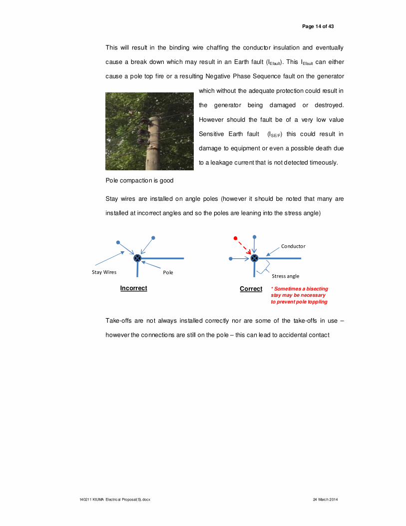
Pole compaction is good
Stay wires are installed on angle poles (however it should be noted that many are
installed at incorrect angles and so the poles are leaning into the stress angle)
Take-offs are not always installed correctly nor are some of the take-offs in use –
however the connections are still on the pole – this can lead to accidental contact
Pole Stay Wires
Incorrect
Conductor
Stress angle
* Sometimes a bisecting
stay may be necessary
to prevent pole toppling
Correct
140211 KIUMA Electr ical Proposal(S).docx 24 March 2014
Page 15 of 43
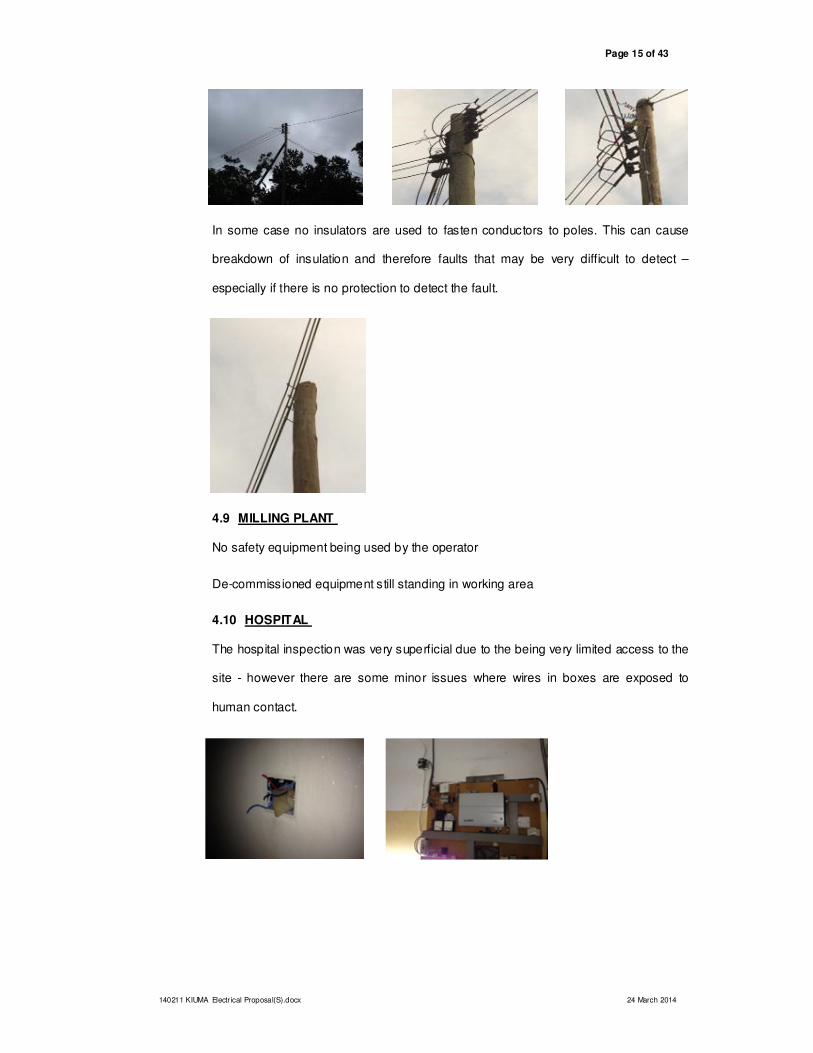
In some case no insulators are used to fasten conductors to poles. This can cause
breakdown of insulation and therefore faults that may be very difficult to detect –
especially if there is no protection to detect the fault.
4.9 MILLING PLANT
No safety equipment being used by the operator
De-commissioned equipment still standing in working area
4.10 HOSPITAL
The hospital inspection was very superficial due to the being very limited access to the
site - however there are some minor issues where wires in boxes are exposed to
human contact.
140211 KIUMA Electrical Proposal(S).docx 24 March 2014
Page 16 of 43
The battery bank appear to be relatively new and in good condition – this looks to be a
sealed maintenance free lead acid bank
The Solar Array appears to be operating well – supplying the hospital batteries -
however the 220Vac input to the inverter is faulty – needs to be repaired.
4.11 GENERAL SITE
It was noted in the new ‘Finance office” that the main Distribution Board has been
wired incorrectly. The main incoming feeds are fed into the bottom of the breakers
when they should be fed into the top with the load being taken from the bottom. This
means that the breakers may work when detecting a fault but may not work
correctly.
In the new Finance Room – there has been a splitting of phases and a splitting of
protection circuits – the standard / principle used here appears to be very irregular and
should be seen as hazardous – it is the writers recommendation that this buildings
wiring should be removed and re-instituted to acceptable safe standards
140211 KIUMA Electr ical Proposal(S).docx 24 March 2014
Page 17 of 43
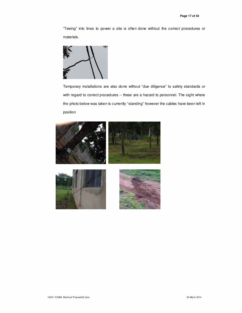
“Teeing” into lines to power a site is often done without the correct procedures or
materials.
Temporary installations are also done without “due diligence” to safety standards or
with regard to correct procedures – these are a hazard to personnel. The sight where
the photo below was taken is currently “standing” however the cables have been left in
position
140211 KIUMA Electrical Proposal(S).docx 24 March 2014
Page 18 of 43
5. MMMSA “GENERAL IMPRESSIONS”
5.1 “GOOD PRACTICES”
� Overhead lines use recognised conductor (Airdac) and recognised “tagged”
poles. It would appear too that all poles are buried to correct depths (16% of
pole length)
� Attempts have been made to use a standard on O/H pole-tops with regards
“bobbins” and “tying in”.
� Pole compaction is good
� Stay wire are installed on angle poles (however it should be noted that many
are installed at incorrect “bisecting” angles and so the poles are leaning into
the stress angle)
� Original installations were done to a high standard (however they have since
deteriorated)
� Building electrical installations appear to be safe and well installed (however
standard installation procedures are not consistent over the entire complex)
5.2 “BAD PRACTICES”
x No site “as built” Overhead system electrical drawings are available – detailing
conductor type, size, length or position
x No standards installation procedures are used for domestic installations:
• houses are wired according to each installers own interpretation
• excessive use of materials result in over expenditure at some installations which also leads to redundancy on protection of systems
x Correct phase load balancing is not practised and so it appears as if the RedØ
is excessively loaded while the WhiteØ and BlueØ are under loaded. This has
resulted in a large imbalance on the O/H system as well as the Generator
supply. (See point 5.i)
140211 KIUMA Electr ical Proposal(S).docx 24 March 2014
Page 19 of 43
x Trees are encroaching on the O/H lines and these can cause the lines to
break under windy conditions
x 3-Phase (3Ø) is used into some houses – this is totally redundant when
looking at loading. This may have been done because of Air Conditioner (A/C)
usage but it would be recommended that A/C units are only installed in
essential areas not domestic or office facilities as this places undue burden on
the Generator set as well as induces imbalance current should the loads not
be connected correctly to allow for Single Phase (1Ø) take-offs.
x Throughout the complex decommissioned wiring is left in place while
telephone and television wiring is running alongside power supply cabling –
this can lead to personal injury if handled by inexperienced or untrained staff
5.3 SAFETY (ELECTRICAL INSTALLATION AND MACHINERY)
� No Safety Standards are in place and staff not trained in these standards
� Staff who monitor equipment are not adequately trained
� Some machinery has exposed moving parts – no guards in place to protect
operators or passers-by
� No standard operating procedures in place for machinery or Electricity
Network operations
� Operators of “noisy” machinery not using ear protection
� Operators of “moving / cutting” machinery not using eye protection
� Welders not using eye protection
� Welding workshop has inadequate lighting for safe working
140211 KIUMA Electrical Proposal(S).docx 24 March 2014
Page 20 of 43
� Carpentry / joinery workshop has inadequate lighting for safe working
� Milling room has inadequate lighting for safe working
� Battery room has no eye protection available (full face shield – splashing
Sulphuric Acid H2SO4)
� Battery room has no hand protection available (full leather gloves)
� Battery room has no body protection available (leather apron)
� Battery room has no body cleaning protection available (shower / water
source)
� Carpenters working on machinery not using breathing masks
� Carpenters working on machinery not using eye protection
� Carpenters working on machinery not using gloves
� Carpenters working on machinery not using ear protection
� Metal roofs are not adequately earthed – cannot dissipate faults
� No lightning protection is installed at any of the supply points or end user
points
� No lightning masts are installed around the property to alleviate the possibility
of building strikes
� All fire extinguishers service dates outdated – should a fire occur then these
will be of no use
� There is no central library / storage area for all documentation of manuals for
equipment
� A major concern is around the earthing of the generators and the
reticulation network. Should this earthing be inadequate then the
possibility of serious injury to people of damage to equipment is
multiplied. Earthing is critical to the safe working and electrical integrity
of any system. This needs to be investigated as a matter of urgency.
140211 KIUMA Electr ical Proposal(S).docx 21 03 April 2014
6. LOADING TABLE (INCLUDING LOADING ASSUMPTIONS)
140211 KIUMA Electr ical Proposal(S).docx 24 March 2014
Page 22 of 43
140211 KIUMA Electr ical Proposal(S).docx 24 March 2014
Page 23 of 43
140211 KIUMA Electr ical Proposal(S).docx 24 March 2014
Page 24 of 43
140211 KIUMA Electrical Proposal(S).docx 25 03 April 2014
7. MMMSA RECOMMENDATIONS
7.1 ESSENTIAL 1 - GENERATOR ROOM UPGRADE
The # 1 JOHN DEERE diesel generator is currently in service supplying both the
complex as a whole and the small water pump alongside the generator room (details
unavailable)
This unit has the power capability of running the
entire complex under a load condition of 54%
diversity (see point 7 - loading table). It is
crucial to the electricity security of the complex
that this generator be serviced so that it is
available at all times to supply KIUMA
The only negative point with regard this unit is that its fuel consumption is high –
15L/hr
The # 2 IVECO AIFO diesel generator is currently out of service and it’s availability
for service could not be determined.
This unit has the power capability of running the
entire complex under a load condition of 35%
diversity (see point 7 - loading table).
Relatively high fuel consumption – 10L/hr
It is also essential that this unit be serviced and made ready for use. It stands as a
“back-up” to the #1 generator should that unit need servicing or repairs.
140211 KIUMA Electrical Proposal(S).docx 24 March 2014
Page 26 of 43
The # 3 GREAZZO VICENZA ITALY diesel generator is currently running the water
pump at Borehole #1.
Fuel consumption – 5L/hr
This machine is far under-utilised for its power
delivery capacity and it is recommended that it be
moved to the site of the Borehole #1 pump house
and be used as a dedicated supply for both
Borehole #1 and the future Borehole #2 pump.
The #4 JOHN DEERE diesel generator is currently out-of-service at present and
needs urgent attention. It is also generally used to supply the pump at Borehole #1
when serviceable.
Fuel consumption – 7L/hr
It is also recommended that this generator be moved to the new site alongside the
Borehole #1 pump house. This can be used as a back-up to generator #3 when it is
moved. This will allow the other to be serviced / repaired without any loss of pumping
capacity.
140211 KIUMA Electrical Proposal(S).docx 24 March 2014
Page 27 of 43
The generator room is in serious need of maintenance, cleaning and refurbishing (if
possible). There are numerous cables still attached to equipment that is no longer
serviceable or in use. These are a hazard.
It would also be recommended that the building be painted and adequate lighting
installed to ensure safe lit working conditions. The floor can also be painted with a
diesel repellent so as to protect the concrete from becoming corroded – this will also
allow for easier cleaning should a spillage occur.
It is also a recommendation that the main supply boards be removed and cabinet
mounted units be installed. These cabinets should be fitted with the necessary
generator electrical controls, generator protection relays and outgoing line protection.
As both Gen #1 and Gen #2 can / are to be used to supply the reticulation network it is
recommended that the cabinet be wired in such a way that they:
• can work independently of each other (“chop-over” installed)
or
• can be utilised in parallel – HOWEVER this facility needs careful attention as the two units have differing output capacities and should they be running simultaneously under heavy load (above 35% diversity) the load may be distributed between them to the detriment of the smaller Gen#2. Requires
complicated control circuitry.
This cabinet will ensure safer operating conditions for the operating staff as well as
greater efficiency in supplying power to the complex.
140211 KIUMA Electr ical Proposal(S).docx 24 March 2014
Page 28 of 43
NB! - It is also recommended that a diesel fuel tank (with level indicator) be
installed adjacent to the building that will allow for a gravity feed into both
Generators (+- 500 litre capacity should be sufficient) – this can also be mounted on a
small platform to allow for sufficient “fall”. This tank will allow for at least 40 hours use
by the generators (when running singularly or 20 hours running in parallel). This tank
can be filled from outside of the generator room and so alleviates possible diesel spills
as well as the possibility of fire should the diesel ignite within the building.
7.2 ESSENTIAL 2 - BATTERY ROOM UPGRADE
At present, the battery room is a hazard. Cabling is in disarray, the control board is not
labelled adequately, the lighting is insufficient, the room is dirty and the batteries
themselves are filthy. It is difficult to determine how this system is integrated into the
rest of the network.
It is recommended that the room be painted with a
good white wall coating while the floor is provided with
a good covering that will protect the concrete from
spillage of acid.
The barricade to cordon the batteries off from the rest of the room is a hazard as it can
cause the operator to trip and fall into the batteries possibly cause a short circuit on
contact. This DC short circuit current can run in the hundreds/thousands of Amperes –
this may not be lethal contact but the operator can be severely burnt.
It is also recommended that the battery output be connected to an “insulated” copper
busbar that runs along the wall and is then connected into a control panel fitted to the
wall. This panel will house all the control circuitry and protection necessary to monitor,
control and protect the battery bank and its feed into the network. The capacity of the
bank needs to be calculated correctly - Full load Current (IFL) and No-load current (INL)
needs to be determined and the bank sized accordingly. A DC Battery Bank specialist
is recommended to do this calculation and a recognised installer be utilised to carry
out the necessary battery room upgrades and installations.
140211 KIUMA Electrical Proposal(S).docx 24 March 2014
Page 29 of 43
The current invertor has no 220Vac input capability and the spare unit is
unserviceable – these faults need to be corrected as a matter of urgency – again by a
recognised DC specialist.
7.3 ESSENTIAL 3 - MAIN SOLAR ARRAY MAINTENANCE
The suitability of this bank needs to be ascertained by a recognised Solar Energy
Specialist and then if suitable it needs to be serviced – especially with regard “sun
tracking” and cabling. The connection to the battery bank needs to be checked and
corrected. This connection is not labelled nor can it be determined accurately how it
connects into the existing network.
7.4 ESSENTIAL 4 - HOSPITAL STANDBY GENERATOR ROOM
Due to the nature of the work carried out by the hospital it is essential that the hospital
have an “emergency services” supply capability. The power supply to the hospital
needs to be secure and stable . Should the power fail during surgery the resulting
disaster could have far-reaching effects on the KIUMA ministry in Tanzania.
Therefore, it is recommended that the hospital receive its own dedicated generator
supply room.
The hospital currently runs off the existing generator supply which is adequate. A
battery system with Solar Array charging is the standby supply. This system can be
maintained however it does need to be maintained and proper control panels installed
with correct labelling (this system can become back-up No.3). A new generator supply
room should be installed that will become back-up No.2.
7.5 POWER SUPPLY ORDERING:
1st.Main Generator supply
2nd. Hospital Standby Generator
3rd. Battery / Solar Array
140211 KIUMA Electrical Proposal(S).docx 24 March 2014
Page 30 of 43
Should the main supply fail and the generator fail to start then the control panel should
engage the battery / solar back-up system. This new arrangement will ensure that the
hospital operating theatres are always supplied with power. The new system also
allows for maintenance for crucial supply units without endangering power supply
security.
KIUMA currently have a suitable generator in storage on site (DIMAGG Listen Petter
diesel 3Ø 180kVA). This unit should be suitable to supply current needs as well as
the future extensions and related power demands. All that is required is the necessary
room, control equipment, fuel supply unit and cabling into the existing supply network
NOTE: This standby unit should not be used to “shore up” the existing power
network as this may have a negative effect on its performance and emergency
status.
The position of the standby room is recommended to be alongside the current Hospital
Solar Array as this allows for minimal cabling into the existing network.
8. MMMSA SUGGESTED OPTIONS
8.1 OPTION 1 – STATUS QUO
This option is available however it comes with many negatives. At present the
electrical system operates but not at optimum capacity.
Should this option be exercised then KIUMA need to understand that the current
problems will not only continue but will in all probability worsen:
140211 KIUMA Electrical Proposal(S).docx 24 March 2014
Page 31 of 43
• Loading imbalances become greater
• Overhead backbone system becomes increasingly overloaded
• Overhead backbone system becomes increasingly susceptible to faults and downtime
• Battery capacity diminishes with each loading cycle and will eventually fail
• Solar Array capacity diminishes
• Internal building wiring and security remains without standards or procedures and so becomes a liability to all users and operators
• Fault finding remains a hazard
• The possibility of extended downtime of power supply multiplies as the existing network setup ages.
8.2 OPTION 2 - UPGRADE OVERHEAD BACKBONE SYSTEM ONLY
This option provides for minimal system enhancements at minimum cost. The current
system overheads are running near capacity which means that the effective lifespan is
diminishing due to overloading - as new user points are added the loading increases
and the aging process increases. By upgrading the overhead backbone (main supply)
the loading rate decreases which allows for more end users to be connected. This,
however, cannot provide an unlimited source of supply points and so needs to be
monitored closely – the ability to carry full load for an unlimited time is not possible.
The end users / loadings added will determine the lifespan and capacity of the newly
installed backbone.
It is recommended that the backbone be upgraded to either 25mm2 Aerial Bundle
Conductor (ABC) or 25mm2 Airdac (3 x single phase lines + Neutral). This system
however will need to be determined and calculated by a recognised professional line
designer utilising a power flow / profiling package.
The system should also be fitted with the necessary hardware (poles, bobbins, ties,
stays etc) as well as in-line links to facilitate easier fault finding and system versatility.
Normally Open Points (NOP’s) should also be incorporated into the design to allow for
the network to be “fed via different routes” – this will allow for easier fault finding and
system versatility.
140211 KIUMA Electrical Proposal(S).docx 24 March 2014
Page 32 of 43
All take-off points to end users should be via a Pole-top Box (PTB) that incorporates a
protective device (MCB) to protect the overhead line from end user faults. The integrity
of the overhead line is better using these PTB’s.
8.3 OPTION 3 - TEACHERS TRAINING CENTRE GENERATOR ROOM
This option keeps the existing system connected as it is (or allows for the backbone
upgrade) but allows for an additional Generator room to be built at the proposed
Teachers Training Centre (TTC). This will cater for all expansions around this area of
the complex but does not alleviate problems caused by the long supply run to the
Vocational School Workshops fed from the existing generator room – this area does
put a certain drain onto the supply network.
It is also a rather costly exercise as a new generator needs to be purchased and a
room built to house the generator and all its related control and protection circuitry.
It only alleviates a minimal loading problem and should not be seen as a long term
solution to the current electrical system shortcomings.
140211 KIUMA Electrical Proposal(S).docx 24 March 2014
The two systems are linked together by means of a set of pole mounted links that
have an interlocking system connected to them. This system will only allow the links to
be closed should all the necessary requirements be met by both generator rooms ie
• synchronised speed
• correct phase angle
• correct phasing
• balanced load
(These are not the only criteria and so this system does need to be designed and
installed by a competent recognised person / company)
Running with either of these options - 4a or 4b - allows for a marked increase in
system capability – each has distinct advantages and disadvantages – these will need
to be explored by KIUMA (and the relevant designers) to see which will give maximum
benefit to the complex for least capital outlay (although capital outlay should not be an
exclusion detail).
140211 KIUMA Electrical Proposal(S).docx 24 March 2014
Page 35 of 43
• Option 4a will be the cheaper option but will give limited long term benefits.
• Option 4b may be the most expensive yet the long term benefits will support the capital outlay.
(Will the outlay compensate for future expansion and bring a greater return – that
needs to be decided by KIUMA)
8.7 OPTION 5 – 1 X 500KVA 3Ø CENTRAL GENERATOR
A simple solution is to upgrade the existing overhead network and install 1 x 500kVA
generator with all related control circuitry and protection devices. This unit is then
connected to the network which then encompasses the entire complex Eastern area
and Western Area
9. CONCLUSION
The complex appears to be able to cope with the existing loading and design of the electrical
network – however the current situation will not be sufficient for the KIUMA complex to continue
operating well into the near future.
� Equipment is not being maintained,
� New buildings are being added to the loading without the network capacity being upgraded to meet the new requirements
� Standard installation procedures are not being used – this leads to a variety of practices all of which affect the safety, capacity and electrical integrity of the current system (and future system should this not be addressed)
� A variety of “imported” equipment is being used – this does not allow for easy maintenance or for readily available spares to be obtained. Local equipment needs to be utilised or sufficient spares need to be kept on site (this can be a very costly exercise)
� Installation staff are not suitably trained
An intervention is required soon to reduce the drain on the current supply network as well as to
determine a set of compliance standards – should this be delayed then the network is going to
collapse or personnel are going to be injured.
MMMSA is available to continue the investigation process however this will need to be
negotiated as this process will need more time, more equipment and more personnel.
140211 KIUMA Electrical Proposal(S).docx 24 March 2014
Page 36 of 43
10. DISCLAIMER
Due to the high-level visual inspection concept applied to this project and the fact that no in-
depth testing or intrusive inspection was done it should be noted that the recommendations of
MMMSA are for guidance and planning purposes only .
Precise and specific recommendations can only be made after:
1. specific load studies are carried out
2. O/H routes and lengths are determined accurately
3. underground cable route, cable sizes and cable lengths are determined accurately
4. detailed reticulation load studies have been carried out
5. future loading expectations have been determined
6. future building plans have been determined
7. existing “out of commission” equipment has been restored to service as this will determine capacity
MMMSA cannot be held responsible should any of its planning recommendations be
implemented without further detailed investigations or designs being carried by qualified
professional persons.
140211 KIUMA Electrical Proposal(S).docx 24 March 2014
Page 37 of 43
11. APPENDIX A
Report supplied by wortuntdat (Germany)
– “Current electric report”- Jakob Adolph (Project Manager)
Power supply generators GENERAL
We have two big questions.
1) How can the diesel generators be used best for all the electric power needs in
KIUMA?
2) Knowing that there always be long hours of generator use every day, how can the
solar power and battery banks be designed to cover the generator OFF hours and
emergencies for the hospital and vital administration (directors house) and
communication needs.?
The bottom line
• We need to find a Tanzanian technology provider for each of these questions,
preferably one that can give us qualified answers to both issues. (best use of
generators and solar power)
• We want to provide a reasonable learning and work experience for all staff
and students in KIUMA.
• We want to reduce times when “things cannot be done” because there is no
electric power, yet at the same time we want to maximize the use of electric
power when it is ON.
• We want to have an emergency power system in place, for situations when
the generator power is interrupted, no matter for how long.
The remarks below are not in any order of priority.
• Appropriate sized generators should be chosen for different times of the day.
• The water pump needs to run on the same generator as the general electric
supply. Currently the water pump runs only on an “exclusive” generator #3 or #4. This
is due to water pump failures in the past. The “mix” of pumping water and generating
power for various applications in KIUMA was blamed. Possible reasons for these past
failures could have been the “consumption spike” when various electric motors start up
with the generator. Possibly the max. available power was reached on startups. It must
be assured that the generator in use is powerful enough to start ALL attached electric
motors including the “startup spike”.
Before this new “hookup” is tested it must be assured that there is a “spare” water pump
in KIUMA in case this would not work of other not yet identified reasons for failure.
• A detailed List of electric power consumers must be established. There are too many to
mention here, but the biggest ones are:
-All hospital surgery equipment (high wattage lamps, AC´s etc)
-All lights on the entire compound, especially the high beam in the church and the Aula,
there are approximately 130 different sized buildings, providing housing, schooling
facilities, and general living quarters. There are more than 1100 People on the property,
not counted the inpatients at the hospital, a different sized groups that might come for
various meetings and conferences.
140211 KIUMA Electrical Proposal(S).docx 24 March 2014
Page 38 of 43
With the extensions and growth expected in the next 24 month, everything should be planned
for at least 1500 residents.
-Various water heaters (especially in the hostel and the Level “A” housing units
-All carpentry and joinery woodworking machinery
-All welding and fabrication machinery
Schedules need to be made of which equipment can NOT be used at the same times! For
example (not more than 3 electric machines in the woodworking shop at the same time or not
more than 2 electric welding machine in the welding and fabrication workshop etc.) These
schedules need to be based on realistic evaluation of the power needs in KIUMA.
• The current generator times need to be adjusted to the agreed times:
08:30-11:30
19:00-23:00
At least, to raise life quality of all personnel and students, and to increase the time the
water pump is running to increase water quantity.
(A second well and pump might be considered for 2014 to cover the expected growth of
the project and to provide water to the Milonde village)
Also it should be considered to run the generator in the afternoons to give more work
time to the VTC machinery, the hospital and the IT classes.
A completely new schedule might be considered, covering the mornings, afternoons
and evenings.
Battery bank and solar power
• KIUMA has two separated solar panel systems, both with its individual battery bank.
(See attached schematic document)
The system at the hospital is vital and it should be the first priority to have an
independent working system in place.
The system supplying the hostel and the directors house is of secondary priority and it
should be a KIUMA decision on how large this system needs to be and if the
guesthouse really needs a 24/7 power supply.
In both cases the reality is that due to the size and type of electric appliances used,
there will be no meaningful “solar only” solution, but there will always be a need to run
diesel generators for the biggest consumers.
So any new or revamped installation should be taken into account that there is a generator
running a few hours every day anyway. At the same time, for cases of emergency the hospital
needs to be able to run for long periods of time only on battery and solar power.
• It also should be considered to combine all solar panels and battery banks into one
powerful system at the hospital (or at the generator house) with the option of supplying
a small Amp line to the directors house for emergencies (to run the lights, satellite
communications and IT)
• All batteries are quite old and tired (with a small exception of added batteries), a full
replacement needs to be considered.
• It needs to be discussed with the hospital doctors which of the equipment needs to be
running in any power situation to find out what the minimum size of the solar and power
bank system needs to be.
140211 KIUMA Electrical Proposal(S).docx 24 March 2014
Page 39 of 43
#1 Generator John Deere, diesel installed 2011 (15Ltr/h)
KVA/KW 23/18
Max KVA/KW 260/208
Volt 400/230
Freq. 50Hz
RPM 1500
Phase 3
Used only when the other generator is in maintenance, due to the higher consumption