108
fi Field Engineering 8 Maintenance Manual 4 0 8 Printers

fi Field Engineering 8
Maintenance Manual
4 0 8 Printers
Major Reuision, November 1964
This manual, Form 225-6493-4, supersedes and obsoletes both the previous edition, 225-8493-3; and Form 225-3282-0.
The information in both those publications is consolidated, reorganized, and updated to the latest engineering levels.
New information includes procedures for: new style ribbon- shield replacement, hydraulic unit oil-seal replacement, Model 3 train cartridge gear replacement, and accumulative slugto-slug clearance adjustment, as well as a regrouping of related adjust- ments under Print Quality Adjustments.
New information is included for the Model 6, and some Figures are added to support the text where necessary.
Address comments concerning the content of this publication to IBM Product Publications, Endicott, New York 13764.
O 1960, 1961, 1962, 1963 by International Business Machines Corporation

Contents
........ IBM 1403 Printer Models 1. 2. 3. 4. 5. and 6 5 Introduction ............................................................................ 5 Safety ...................................................................................... 5 Preventive Maintenance ........................................................ 5
............................. ............................. Installation Procedure : 5
.......... ................................................. Service Procedures 10 ........................................................................ Cover Removal 10
Manual Controls: Adjustment ............................................ 11 .................................................................. Forms Positioning 15
Base Adjustments and Removals ............................................ 21 Chain Cartridge ..................................................................... 30 Hammer-Unit Assembly .......................................................... 37 Ribbon Unit ........................................................................... 41
. Tape-Controlled Hydraulic Carriage ....................... 51 Hydraulic Unit ...................................................................... 51 Carriage Adjustments ....................................................... 57 Carriage Adjustment with the Tachometer-
Generator ............................................................................ 63 Single Shots ............................................................................ 65 Static Adjustment of the Carriage-Tape Brushes ................ 70 Dynamic Adjustment of the Camage Tape Brushes ............ 71
Information Peculiar to the IBM 1403 Model 3 Service Procedures ................................................................
............................................ Manual Controls - Adjustment
............................................ Base Adjustments and Removals .................................... Train Motor Drive-Gear Adjustment
IBM 1416 Train Cartridge ...................................................... .................................................................... Train Lubricator
Hammer-Unit Assembly ........................................................ ............................................................................ Ribbon Unit
Print Quality Adjustments .................................................... Impression Control Bar Adjustment .................................... Timing Disk Transducer Adjustments ................................
.................................................. PCS Transducer Adjustment
Print-Quality Concepts .................................................... 95 Printing Characteristics Defined ........................................... 95 Print-Quality Measuring Devices ........................................ 95 Printer Checks and Adjustments to Meet
Optical-Reader Requirements ............................................ 98 Specific Print Problems and Their Cure ........................... 98
Locations and Voltage Specifications .................... 102
Appendix ............................................................................ 103 ~ ~
Oscilloscope Waveform Charts ............................................ 103 Print Troubleshooting Reference Chart ............................ 104
Index , .................................................................................. 10.j


IBM 1403 Printer
Models I , 2, 3, 4, 5, and 6
This maintenance manual is a companion-piece to Cus- tomer Engineering Manual of Instruction: IBM 1403 Printers, Form 225-6492. It includes information neces- sary for the correct servicing of the 1403 printers. The manual is arranged in three sections.
The first section (Models 1, 2, 3 , 4 , 5 and 6) contains information common to all 1403 models except for those differences peculiar to the Model 3. Special tim- ings or adjustments required for the single-speed Model 6 are noted, as required.
The second section contains additional Information Peculiar to the Model! 3. The great differences in the printing mechanisms of the Model 3 warrant placing this information in a separate section more readily available to the reader.
The third section contains general information on Print Quality Concepts, and applies equally to all models.
Be visually alert for trouble indications any time you service the machine. Look for corrosion, wear, cracks, burned contacts, and loose connections. Watch for filters clogged with dirt.
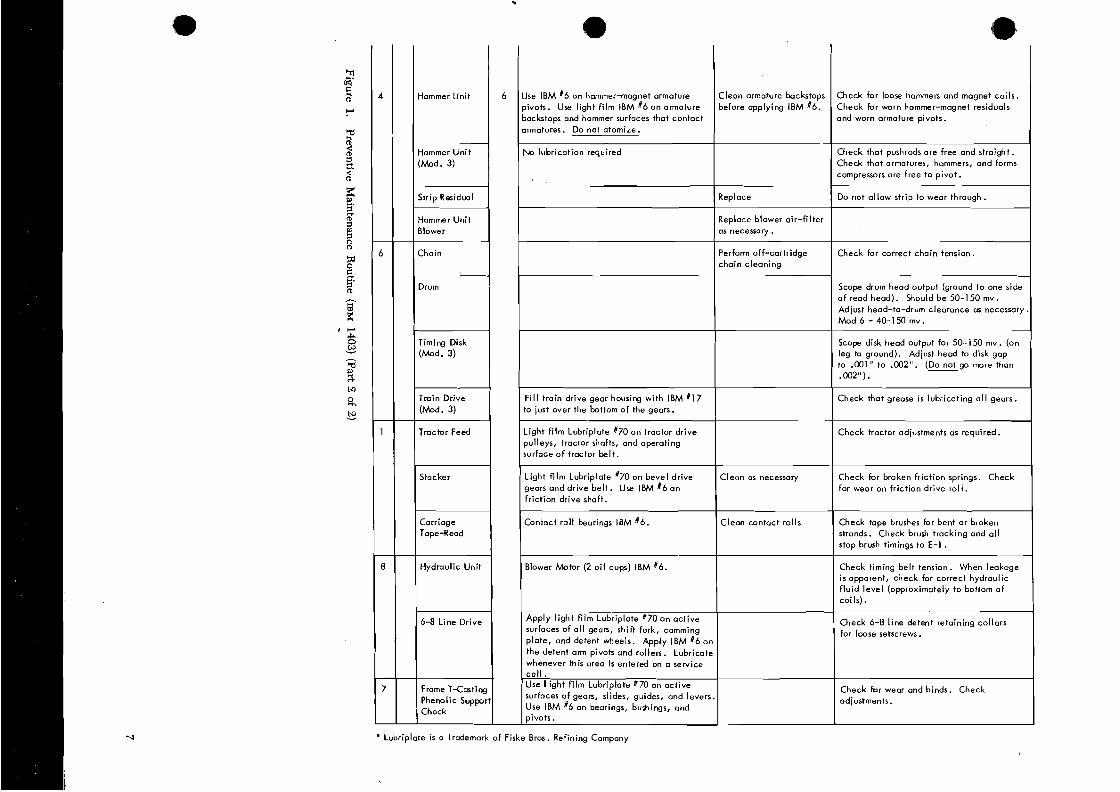
The three basic steps of preventive maintenance are: clean, lubricate, and inspect. Do not do more than the preventive maintenance scheduled on equipment that is operating satisfactorily. Figure 1 shows the recom- mended preventive maintenance for single-shift opera- tion. When used by more than one shift daily, increase the maintenance frequency accordingly.
Apply lubrication only in the quantity necessary to supply the immediate area involved. Wipe off excess. On the 1403, take special care to keep lubricants away from:
Ribbon Cover seals Paper path Rubber dampers Electrical wiring Grommets
e Ribbon drag brakes
.% Safety
- - " The process meter should be checked every six months as prescribed under Installati& Procedure.
Personal safety cannot be overemphasized. To insure your own safety, make it an everyday practice to fol-
8 low all safety precautions at all times. Become familiar with and use the safety practices outlined in Form lnsta//atjon Procedure 229-1264, a pocket-sized card issued to all customer engineers.
Base Installation The 1403 mainline CE switch turns off all ac power
except 115V ac at the convenience outlet. It does not 1. ~ ~ ~ o v e protective wrappings, tape, etc-7 and the
affect the dc voltages. Use this switch only when sys- wooden block used to prevent the translator frame tem power is off. from shifting during shipment.
Caution: Remember if ac power is on, opening the T-casting 2. Make a visual check for parts broken or damaged . removes two phases from the chainhrain drive motor. The in transit. other phase remains present on this motor. A11 three phases re- main on the hammer unit blower and the hydraulk drive motor, 3. Check manual knobs, levers, and covers for correct which continue to run regardless of the gate interlock switch. operation.
4. Check for oil as follows:
a. On Models 3 and N-1. See that the clear plastic Preventive Maintenance train lubricator beneath the lower right end of The prime objective of maintenance is to provide maxi- the T-casting contains special lubricant (part mum machine availability to the customer. Unless a 856381). Prime the pump (see Train Lubricator, preventive maintenance operation reduces machine steps 2 and 5).
u downtime, it is unnecessary. b. On all other models. See that the reservoir be- Do not adjust or disassemble a unit that is working hind the clear plastic window in the right end
properly, even if tolerances vary from specifications. of the T-casting contains ~ B M 6 oil.

1 P.M. ROUTINE 2 1
Choin
LOCATION F ~ ~ Q . LUBRICATION CLEAN OPERATION
F i l l right o i l reservoir in T-casting IBM 16
OBSERVE
Cleon type with vacuum cleoner as required. Cleon typeface with IBM cleaner, P/N 451529
Check that reservoir never runs dry. Check that o i l reaches the chain. Check for chain binds. I f bind is detected, off-cortridge cleaning.
Check that o i l is available a t end o f wick i n movable base. Check by pressing a white piece of paper against the wick. A light o i l f i lm on the paper indicates suf- ficient lubrication.
Train (Mod. 3)
Ribbon Drive Mtr.
Bearing o i l cups (2 oi l cups) IBM 16 (8 drops each cup).
Toggle plate pivot IBM 16. Reverse toggle anchor IBM j24. Skew roller pivot IBM 16.
Wipe excessive o i l and greose from al l areas to prevent contaminating ribbon.
Check for wear and correct ribbon reverse and skew operation.
A l l gears Lubriplate *70 grease (light fi lm). A l l bearings, pivots, and clutch shafts IBM f 6 . Friction-disk interposer stud and bal l IBM f 6 .
Keep friction reverse-drc surfaces o i l free. Wipe excessive o i l and grease from a l l surfaces to pre- vent contamination of ribbon.
Check for wear and binds. Check for correct operation.
to cup on top (may have screw instead o f cup). With oil-level hole: Fi l l with IBM 1 to oil-level hole. Replace screw.
Light fi lm o f Lubriplate 170 on eccentric and geors.
Light fi lm o f Lubriplate 170 on eccentric
l . Light fi lm Lubriplate #70: drive key, pinion, Intermediate, and drum gears.
2. Add 122 to bevel gear unit (see lubricating Bevel Gear Unit) I
Light f i lm L u b r i p G j70 on;. ksy . I F i l l o i l reservoir with special lubricant, P/N 856381
Check accumulated slug to slug clearance. Free troin movement w i th .001" between butts o f two type slugs. Slight binds i n train with .003" gage.
Check for proper grounding. Check ground- ing strips for foreign material.
Lubriplate is a Trademark of Fiske Bros. Refining Company
Check for loose hammers and magnet coils. Check for worn hammer-magnet residuals and worn armature pivots.
Check that pushrods are free and straight. Check that armatures, hammers, and forms compressors are free to pivot.
Do not allow strip to wear through.
Check for correct chain tension.
Scope drum head output (ground to one side o f read head). YIould be 50-1 50 mv . Adjust head-to-drum clearance as necessary. Mod 6 - 40-150 mv.
Scope disk head output for 50-1 50 mv . (on leg to ground). Adjust head to disk gap to .MI" to .002". (Do - not go more than .M2").
Check that grease is lubricating a l l gears.
Check tractor adiustments as required.
Check for broken friction springs. Check for wear on friction drive rol l .
Check tape brushes for bent or broker1 strands. Check brush tracking and a l l stop brush timings to E - l . Check timing belt tension. When leakage is apparent, check for correct hydraulic f lu id level (approximately to bottom of coils).
Check 6-8 line detent retaining collars for loose setscrews.
Check for wear and binds. Check adjustments.
4
6
1
8
7
Clean armature bockstops before applying IBM 66.
Replace
Replace blower air-fi lter as necessary.
Perform off-cartridge chain cleaning
Clean as necessary
Clean contact rolls
Hammer Unit
Hammer Uni t (Mod. 3)
Strip Residual
Hammer Unit Blower
Chain
Drum
Timing Disk (Mod. 3)
Train Drive (Mod. 3)
Tractor Feed
Stacker
Carriage Tape-Read
Hydraulic Unit
6-8 Line Drive
Frame T-Casting Phenolic Support Chock
6 Use IBM 16 on hammer-magnet armature pivots. Use light fi lm IBM 16 on armature backstops and hommer surfaces that contact armatures. Do not atomize.
No lubrication required
F i l l train drive gear housing with IBM 617 to just over the bottom of the gears.
Light fi lm Lubriplate 170 on tractor drive pulleys, tractor shafts, and operating surface o f tractor belt.
Light fi lm Lubriplate #70 on bevel drive gears and drive belt . Use IBM i 6 an friction drive shaft.
Contact rol l bearings IBM 16.
Blower Motor (2 o i l cups) IBM 16.
Apply l ight fi lm Lubriplate "70 on active surfaces of a l l gears, shift fork, camming plate, and detent wheels. Apply IBM # 6 on
the detent a n pivots and rollers. Lubricate whenever this area is entered on a service col l . Use I ight fi lm Lubriplate f70 on active surfaces of gears, slides, guides, and levers. Use IBM #6 an bearings, bushings, and pivots.

5. Check for fluid in the hydraulic reservoir (1 gallon, part 477567).
6. Install the signal cable shoe-connectors (SC-1 and SC-2) in the proper receptacles. Connector SC-1 has gold-plated contacts and should be inserted into the front receptacle.
On the Model 3, remove the cartridge blower hose to permit insertion of SC-1, after which you must reconnect the hose.
7. Install two antiwalk feet.
8. Assemble the forms-cart right- and left-grounding guide assemblies.
9. Check all terminal-block safety shields for warp- age before turning machine power on.
10. To insure correct machine performance, it is most important to check the .loo" spacing between the cartridge and the hammer unit on the Model 3 printer (Figure 2). This is a critical dimension. If it has shifted during shipment, print quality can be drastically afFected. Check this adjustment care- fully at both ends and readjust if necessary. (Refer to Figure 18 for other models.)
Line Voltage Wiring Check
Before connecting the power plug to the printer:
1. Determine actual customer line voltage being sup- plied. If a change is necessary, proceed with steps 2 and 3.
2. For line voltages nearest to 208 volts:
a. Place the chain-drive-motor .machine cable on terminals TB-7-1, 7-2, and 7-3. (TB-7 is on the T-casting, to the right of the chain-drive motor, under the chain cartridge and under the ribbon.)
lG/ Alignment Tool ( 452457)
# T ~ ~ ~ ~ T ~ ~ 1 ;
Locating Block
4 h-.lCm~@
Figure 2. Train-to-Hammer Unit Positioning
8
b. Place one ac lead for the elapsed time meter on terminal 4. The other ac lead will remain on ter- minal 1. The ac terminal block is inside the meter cover. To check or change these ac line connec- tions requires a retainer (part 740489).
3. For line voltages nearest to 230 volts:
a. Place the chain-drive-motor machine cable on terminals TB-7-4, 7-5, and 7-6.
b. Place one ac lead for the elapsed time meter on terminal 5. The other ac lead will remain on ter- minal 1.
Three-Phase Motor Rotation Check
1. When the system is ready, turn on the system power, with the T-casting open.
2. Check carriage-motor rotation by observing the ro- tation of the forms stacker rolls. Correct rotation causes paper to stack properly. An IBM card placed between the rolls before power is turned on will give an immediate indication of stacker roll rotation. The card should eject downward.
3. Close the T-casting and check the direction of the rotation of the type-train drive motor. The motor rotation is correct if the train moves counterclock- .
wise when viewed from the top.
4. Make sure the hammer unit blower is blowing air normally into the hammer unit. Some air flow will be felt even if the blower is turning in the wrong direction. Also, make sure the type-train blower is blowing air.
5. Turn off the system power. Do not use the mainline CE switch on the 1403 (toggle switch inside rear cover). This switch should be used only if the sys- tem power is off.
6. If all three-phase motors are rotating in the correct direction, proceed to System Check-Out. If one motor is rotating incorrectly, go to step 7. If all motors are rotating incorrectly, proceed as follows:
a. Turn off the system power.
b. Turn off the power to the wall receptacle.
c. Reverse any two leads at the wall plug, or at the system power-input circuit breaker.
d. Turn on the system power and recheck the motor direction.

7. If one of the three-phase motors is turning in a di- rection of rotation that is incorrect:
b a. Turn off the system power. (Pull the power-plug out of the printer.)
b. Interchange any two of the three leads of the motor.
c. Turn on system power and recheck motor rota- tion.
Carriage Control-Tape Brush Timing
Check the dynamic adjustment of the carriage tape brushes using a tape punched on the customer's tape punch. Refer to Dynamic Adjustment of the Carriage- Tape Brushes.
System Check-Out
1. Check for the correct operation of all printer inter- locks :
Gate (T-casting) End of forms Brush Forms check Shift (6-8 line) Thermal
Observe lights on both printer indicator panels while actuating interlock switches.
L
2. Check and record the read-head output on one of the oscilloscope waveform charts (see Figure 110 in the Appendix). It can then be retained for future reference. The output should be 50-150 millivolts
C for each leg.
Scope between dc ground (pin J) and pins B and D of SA-1 for this reading (see Figure 92). The phasing of the PSS pulses to the differential ampli- fier in the system is extremely important. This can be checked by syncing internal-plus on the output of the differential amplifier, and observing several pulses. The phasing of the PSS pulse is correct if the differential-amplifier output pulse is stable and has a rise time of less than .5 microseconds. A waterfall effect is permissible at the trailing edge of this out- put. (Refer to Timing Disk Transdmer Adjust- ments.)
Note: Reversal of the transducer leads will alter the length of the output pulse.
3. If the printer is being installed with an existing sys- tem, or is a field merge, or field interchange, the
carriage control circuits for single-, double-, and triple-spacing must be adjusted. (Refer to section on Single-Shots.)
4. Give the printer a complete operational test, using test decks 2000,2010,2012 and 2020.
Process Meter Test
All printers are equipped with a process meter. This meter will record time if the system processing unit meter is recording, and if a first print instruction has been received by the printer from the system. A stop condition is established when the printer space key or restore key is manually operated and released, or when the system processing meter stops recording. However, as long as the space or restore key is held down, the meter will record time, provided the system processing unit meter is also recording time. The printer meter stops when the space or restore key is released.
Once started, the printer meter starts and stops with the system start and stop keys, regardless of the pro- gram function, provided no printer stop condition occurs.
Check the printer process meter to see whether it is functioning properly. Use the following test pro- cedure:
1. Enter at address 444 the instruction %449B445-. This will print one line and branch to a loop, which will keep the process M (-U) line active, although the printer will not continue to print.
2. Operate the system start and stop keys. Npte that the printer meter starts and stops under control of the system start and stop keys although no printing is taking place.
3. With the printer meter running (because the pro- gram is operating in a branch loop), press the space key and hold it down. The printer meter should not stop recording.
4. Release the space key, and the printer meter should stop.
5. Restart the program at address 444, and make sure the restore key, when operated and released, stops the printer meter while the system meter continues to run.

Service Procedures
Cover Removal
Top Cover
1. Remove the front cover.
2. Remove the rear cover.
3. Loosen, but do not remove the mounting screws at the rear of the top cover.
4. Tilt the cover down until the left and right stay arms can be unhooked.
5. Unhook the stay arms.
6. Lift the cover, and free it from the rear mounting screws.
7. Replace in reverse order.
Top Forms Guide
1. Lift the front cover.
2. Snap the top forms guide out of the front plastic supports.
3. Raise the front end of the guide.
4. Unhook the spring at the rear right.
5. Unhook the rear end of the guide at the right.
6. Slide the guide off the left rear stud.
7. Remove the guide.
8. Replace in reverse order.
Front Cover
1. Raise the cover.
2. Compress the spring on the stay-arm stud and move the stud to the right.
3. Tilt the cover up until the stud clears the stay-arm.
4. Remove the retaining clip and slide out the hinge pin.
5. Slide the cover to the right and off the left pivot.
6. Reinstall the cover in reverse order.
Left Front Cover Panel (Model 3 and Numeric Printers Only)
Pull the bottom of the panel (Figure 3) forward until
top of the cover clears the two locating pins that go through the holes in the top of the panel.
To replace, slide the cover upwards, guiding the lo- cating pins through the holes in the top of the panel.
C When the panel is up all the way, push the bottom to- wards the rear of the machine until it snaps into place.
Inner Front Cover
1. Remove the following knobs:
a. Manual-clutch and line-selection knob. b. Forms-width vernier knob. c. Manual-advance knob.
2. Remove the CE indicator panel on the inner front cover.
3. Remove the inner-front-cover holding screws.
4. Remove the cover.
5. Replace in reverse order.
Top Cover Adjustment
(Printers without Torsion Bars)
Adjust the spanner-type nut on the stay arms for cor- rect spring tension. The tension is correct if the cover just closes by its own weight to a point where it aligns with the shelf on the upper-left cover assembly. The tension should assure that the top cover will remain open in the raised position.
it clears its snap latch, then ~ulfdownward until the Figvn 3. Left Front Cover Panel Removal/Replnnment

Tie Bar
Lock Lever ~ i b
Figure 4. Translator Frame Lock Lever
Manual Controls: Adjustment Apply Loctite* sealant to the setscrew threads if this adjustment is made.
Translator Lock-Lever
The lever must operate with a positive locking action Vertical Print-Alignment Knob
when a force of four to seven pounds is applied at the 1. Position the eccentric shaft (Figure 6). center of the h o b and perpendicular to the handle. a. The slot in the right end should be parallel with Adjust as follows (Figure 4): the slot in the sector-gear hub, within %".
1. Loosen the translating-frame gib locknut. b. Further adjustments may require that this be
2. Loosen the frame locking setscrew for gib-to-tie-bar altered.
clearance. 2. Position each ball-detent barrel to the periphery of
e 3. Lower the lock lever to the fully-locked position the sector gear:
and recheck for gib-to-tie-bar clearance. a. For clearance throughout full gear rotation.
4. Press the locking mechanism to the rear of the b. For maximum clearance of ,008". machine while holding the locking roller squarely Note: When installing a new ball-detent barrel, insert against the tie bar. the new barrel from the sector-gear side of the mounting
block. This method avoids stripping off too much locking 5. Turn the frame locking setscrew finger tight. material on initial installation.
Note: Make sure the locknut is not against the lock block. *Loctite is a product of the American Sealant Company
6. Tighten the setscrew 90" to 1 8 " .
7. Tighten the locknut. Translator Frame Setscrew (2)
Translator Vernier Knob
Set the vernier to provide a movement of K" (* KC).
1. Clamp the translator vernier knob against the shoulder of the vernier screw (Figure 51.
2. Position the right retaining collar against the knob, Vernier Scr
and clamp the collar to the vernier screw.
3. Position the left retaining collar so that a total end play of .0005" to .002" exists between the two col- lars and the translator-lock lever, and clamp the collar to the vernier screw.
Note: On late machines, the left collar is pinned. Adjust this clearance by using the right collar.
Vernier Knob 4. Tighten the setscrews in the translator-frame bear-
ing to provide a slight drag on the vernier screw. ~i~~~~ 5, Vernier

,Eccentric Shaft 5. Set the print-timing dial at:
Translator Frame
Vertical Print
Figure 6. Vertical Print-Alignment Knob
3. Lock the translator frame.
4. Check for a bind between the bottom of the vernier screw and the lock sleeve of the translator vernier (see Figure 5).
a. Raise the translator frame to its uppermost po- sition.
b. Turn the translator vernier knob to detect a bind.
5. If a bind is not detected, proceed to step 7.
6. Remove the bind between the bottom of the vernier screw and the lock sleeve of the translator vernier.
a. Loosen the clamp screws in the sector-gear hub. b. Turn the eccentric shaft counterclockwise until
the bind is eliminated. c. Tighten the clamp screws.
7. Adjust the sector-gear stop screw:
a. For a minimum clearance of XZ" between the translator frame and the printer casting.
b. For a minimum clearance of K" between the lower edge of the sector gear and the printer casting. .
Print-Timing Diol
(Models 1, 2, 4, 5, ond 6)
1. Place Fpart paper in the machine.
2. Load all H's, W's, or M's into storage for printing.
3. Program for PFUNT AND BRANCH.
4. Select 8-lines-per-inch carriage mode and set the print-density lever at C.
12
a. 20 for Models 1 and 2. b. 15 for Models 4 and 5. c. 11 for Model 6.
Assume 4-part paper is .012" thick. If a microme- ter is available, it is advisable to determine the exact thickness and set the timing dial to the correct number as determined from the chart on the ribbon cover.
Note: There are three different print timing dial charts:
Timing chart decal (part 475644) for Models 1 and 2 Timing chart decal (part 865912) for Models 4 and 5 Timing chart decal (part 889623) for the Model 6.
6. Run the machine for ten to twenty lines.
7. Examine the fourth copy. A faint smudge will be visible showing the outline of each hammer. The relative position of each printed character to the hammer can thus be examined and evaluated.
8. Adjust the timing-dial screw (Figure 7) until the maximum number of printed characters is centered on the hammer impression marks. Maintain the dial setting of:
a. 20 for Models 1 and 2. b. 15 for Models 4 and 5. c. 11 for Model 6.
9. Individual positions are adjusted for centering by the hammer-magnet eccentric adjusting tool (part 451123).
Note: It may be necessary to compromise this adjust- ment to obtain acceptable print density. If the correct harn- mer flight time and print density cannot be obtained, a new hammer-magnet assembly should be installed.
Forms-Width Vernier
1. Adjustment procedure:
a. Move the translator frame to the left. b. Remove knobs. c. Remove the inner front cover. d. Remove the gear guard. e. Locate the left forms tractors in the correspond-
ing extreme left slots in the tractor mounting bars.
f. Locate the right forms tractors in the corre- sponding extreme right holes in the face of the removable slides.
2. Adjust the left tractor-pin feeds horizontally. a. Place a straight edge along the pin feeds to check
alignment.

Print Timing Slide
Figure 7. Print-Timing Dial Adjustment
b. Shift the tractor mounting bars to align the pin c. Keep the left horizontal surface of the lower feeds within .005". There are two screws in each mounting bar against the corresponding horizon- end of each bar (Figure 8). tal lip of the printer casting. The upper mount-
Figure 8. Tractors (T-Casting Removed)

ing bar is positioned up and down by an eccentric washer on current machines. The upper and lower mounting bars must be parallel.
3. Adjust the right tractor pin feeds.
a. Orient the horizontal adjusting screws, horizon- tal-drive collar, and gear to align the right pin feeds within .005", horizontally.
b. Place a straight edge along the pin feeds to check alignment.
c. Reposition (if necessary) the horizontal adjusting screws in relation to the collars and gears to ob- tain adjustment.
d. Position the collars and gears for a maximum end play of .002".
4. Operate the forms-width vernier with light finger force. Adjust the friction screw and block as re- quired.
5. After this adjustment has been made, adjust the vertical position of the right ends of the upper and lower tractor mounting bars for free movement of tractor assemblies.
4rm Spring:
Manual-Clutch and Line-Selection Knob
1. Preliminary procedure:
a. Move the translator frame to the left. b. Remove knobs. c. Remove the front inner cover. d. Remove the gear guard.
2. Check the adjustment of the manual clutch and the line-selection-knob assembly (Figure 9).
a. Check for clearance:
(1) For a minimum-end play of the dentent arms on the shdt .
(2) For a minimum of .025" between the detent roller and the detent wheel when the detent is inoperative.
(3) Between the tines of the shift fork and the shift- . - gear hub.
b. Check for alignment of the:
(1) Detent arms to the slots in the camming plate.
(2) Detent wheels to the detent arms.
c. Check for correct operation to make sure that:
(1) The clutch shifts from 6-line neutral to 6-line drive and from 8-line neutral to 8-line drive.
Figure 9. Manual-Clutch and Line-Selection Assembly (Lower Tractor Shaft Removed)

(2) The detent arm spring causes correct operation of the detent arms and wheels (there should be a force of 4% to 6% pounds on the detent arm).
(3) The detent arm roller seats fully in the detent wheel when the detent is operative.
3. If the conditions in step 2 are met, no further ad- justment is necessary. Proceed to step 11. If not:
a. Unhook the detent-arm springs. b. Loosen both the detent wheels. c. Slide the right detent wheel to the right. d. Loosen the detent-arm collars. e. Slide the detent arms to the left. f. Loosen the camming plate on the shift fork so
that the plate is just free to slide. g. Loosen the setscrew that holds the camming-
plate roller stop rod. h. Wedge some paper between the shift-fork tines
and the hub of the shift gear to center the tines around the shift-gear hub.
4. Position the shift fork on the shift rack for gear mesh and clearance.
a. Detent the shift rack in 6-line drive at the right. b. Position the shift fork on the shift rack so that
the shift gear meshes with the 6-line driving and driven gears and has clearance to the casting.
c. Rotate the shift fork around the shift rack to center the shift fork around the shift-gear hub.
d. Clamp the shift fork to the shift rack.
5. Align the detent arms to the camming plate.
a. Set the shift gear to 6-line drive position. b. Align the detent arms with the left two slots in
the camming plate. c. Tighten the collars to hold the detent arms in
position.
6. Adjust for a clearance between the detent wheels and the detent arms of .025" with the manual clutch in either 6- or 8-line drive.
a. Turn the 6- and 8-line gear idler to a position where it does not move when the shift gear is shifted from the 6-line drive to the 8-line drive, or vice versa.
b. Set the shift gear to the 8-line neutral position. c. Slide the right detent wheel opposite the right
detent arm. d. Use a rubber band to hold the right arm against
the detent. e. Adjust the camming-plate roller stop rod to
provide a .0%" clearance between the detent arm and the teeth of the right detent wheel.
f . Tighten the setscrew to hold the camming- plate roller stop rod.
g. Rehook the springs on the detent arms. h. Clamp the camming plate to the shift fork.
7 . Align the detent wheels to the detent arms.
a. Set the manual clutch to 8-line neutral. b. Align the left detent wheel to the left detent
arm. c. Clamp the left detent wheel to the tractor shaft. d. Set the manual clutch to 6-line neutral. e. Align the right detent wheel to the right detent arm.
f. Clamp the right detent wheel to the tractor shaft.
g. Check the operation of the manual clutch for four manually operated spaces.
h. Readjust as necessary.
8. Set the spring tension to provide 4K to 6!4 pounds force on the detent arm when it is engaged in the detent wheel.
9. Remove the paper from between the shift-fork tines and the shift-gear hub.
10. Position the clutch-interlock switch.
a. The switch must transfer before the plunger completely clears all of the four grooves of the shift rack.
Note: The switch operating plunger must have a minimum of .005" clearance to the rack grooves when detented.
b. Position the switch to obtain this adjustment.
11. Replace the remaining parts in reverse order.
f ormr Positioning
Tractor Shafts and Tractor Mo:~nting Bars Wemovai
This procedure is given for the removal of the upper and lower tractors, the tractor mounting bars, and the drive shafts. If only one set is to be removed, do only as much of each step as will allow the desired set to be removed.
1. Remove the forms.
2. Remove the clip-on paper guides from the tractor mounting bars.
3. Remove the inner front cover.
4. Remove the upper and lower forms-guide bars with the jam bars attached (early machines only).

5. Remove the jam contact mountings from the tractor mounting bars (early machines only).
6. Remove -the wires from the form-stop contacts at the terminal block.
7. Shift the T-casting to the left.
8. Remove the gear guard.
Separate the vertical shaft of the forms-width vernier by loosening the setscrews in the vertical coupling of the forms-width vernier. Move the vertical coupling up onto the upper shaft and lock it to the shaft.
Remove the bearing retaining castings. See Figure 8.
1. Loosen the screws that prevent bearing end shake (at the right).
2. Remove the two bearing-holding screws (at the right) for each bearing retaining casting.
3. Shift the T-casting to the right.
4. Remove the two holding screws (at the left) for each bearing retaining casting (one screw is a dowel).
5. Remove both bearing retaining castings.
Remove the tractor mounting bar and the tractcr shaft.
1. Remove the two screws and the slide-retainer plate at the left end of one of the tractor mounting bars.
2. Remove the two holding screws at the right end of the same tractor mounting bar.
3. Lift the tractors, the mounting bar, and the shaft out and to the left to clear the T-casting.
Repeat step 5 for the other assembly.
Individual Pin-Feed Removal . 1. Open the T-casting.
2. Remove the forms.
3. Open the tractor door.
Remove the tractor paper guides.
1. Remove the tractor paper guide jarthest from the hinge of the door.
2. Remove the iractor guide on the other side of the pin feeds.
Align the pin-feed holding pins with '&e slot in the frame spacer plate (the end nearest the drive shaft, Figure 10).
1. Turn the tractGr shaft until one holding pin aligns with the slot.
2. Use a similar pin to push the installed pin toward the center of the machine (part 804671).
3. Repeat step 2 for the second holding pin.
Remove the pin feed by lifting. Insert the new pin feed.
Replace the pin-feed holding pins.
1. Insert the second pin.
2. Turn the tractor shaft until the first holding-pin hole is aligned with the slot.
3. Izsert the first pin.
Note: Pins are to be flush or slightly recessed.
Replacs the tractor paper guides in reverse order (see Forms-Tracto~. Adjustment).
Forms-Tractor Adjustment
Adjust the belt tension.
1. Maintain parallelism between the axes of rotation of the drive sprocket and of the movable sprocket (Figure 11).
2. Position the movable-sprocket stud for a minimum slack at the point of tightest engagement.
a. Ensure that belt tension is not excessive. b. Tighten the sprocket stud.
Position the beveled ramps.
1. The point of the ramp must point in the direction opposite to the belt motion.
2. Position the ramp for a clearance of .002" to ,007" to the respective sprocket hub.
3. Clamp in position.
Position the tractor paper guides.
1. Align the edge of the paper guide nearest -the door pivot plate flush to the pivot plate.
2. Position the under side of the paper guide flush against the edge of the spacer plate.

uoor rlvl
Movable
Upper T
--..-me
3t Plate -
'ractor Shal
. . Fram
. - c
Figure 10. Tractor (Upper Left)
3. With the conditions in steps 1 and *established, secure both paper guide and mounting block with their front surfaces flush to the front edge of the spacer plate.
4. Position the lower edge of the adjacent paper guide against the lower edge of the paper guide nearest the door pivot, maintaining the upper edges par- allel. Check that the inner edges of the guides are clear of the pins.
@ 5. Fasten the adjacent paper guide to the tractor frame.
Position the tractor door for a clearance of paper guide plates to the door runners of .048" to .056" . (Figure 12).
1. Loosen the pivot plate. -
Note: The Loctite sealant must be used on the threads of the holding screws if this adjustment is made.)
2. Screw the door stop in below the correct door setting.
3. Insert two sets of feeler gages with .the correct setting.

,ed ' lg Pin
Figure 11. Tractor Assembly
4. Force the door against the feeler gages.
5. Tighten the pivot plate.
6. Set the door stop to hold the door at the correct clearance.
%
Pivot Plate Mounting Screws
Cwer Stop -set screw
d just for a Clearance of .048" to ,056"
Figure 12. Tractor Door Clearance
Position the form-stop switch to make when the form-stop lever is within %Z" of the front surface of the paper guide.
Tractor-Mounted Jam-Detection Device Adjustment
Some additional adjustments are applicable to forms tractors that have tractor-mounted jam-detection de- vices. 1. Adjust the jam-detection setscrew so that the jam-
detection switch breaks when the door is opened a '
total of .095" to .118" (Figure 13). 2. Adjust the slide support plate to limit the tractor
door open position. Place a straight edge against the belt-guide step perpendicular to the tractor guide plate as shown in Figure 14. Adjust the slide support plate to obtain %i' -C K" clearance between the door and the straight edge. Be sure to maintain proper belt tension when tightening the plate hold- ing nut.
Upper and Lower Tractor Drive-Shaft Positions
First, check the forms-width vernier. Prepare to adjust the drive shafts. 1. Position the left forms tractors in the corresponding .
slots in the tractor mounting bar.

tors with a minimum slack in paper. Feed the forms manually and check for no elongation of the pin-feed holes (this may occur under power).
The upper.tractor pins should touch the upper edge of the pin feed holes in the form. The lower tractor pins should touch the lower edge of the pin feed holes in the form.
If forms are tighter on one side than the other, ad- just the left end of the upper mounting bar by means of the eccentric washer (on current machines). See Figure 8.
If necessary, adjust the upper tractor shaft drive in relation to the lower tractor drive shaft.
1. Loosen the upper tractor shaft drive gear.
2. Manually rotate the shaft to remove slack. , ,095"- .118" Door Opening 3. Clamp the drive gear to the shaft.
Replace any remaining parts in reverse order. '4 Figure 13. Jam-Detection Switch Adjustment
2. Position the right forms tractors in the correspond- ing holes in the face of the movable slides.
3. Place a form in the forms tractors.
Check the position of the upper drive shaft to the lower tractor drive shaft. The foA must fit in the trac-
Slide
Figure 14. Tractor Door Opening Limit
Tractor installation
This procedure refers to both the upper and the lower assembly. Place the tractor shaft and the mounting bar in relative positions on a flat surface.
Install the tractors on the drive shaft.
1. Slide the drive shaft through the square drive hub on the right tractor.
2. Turn the left tractor drive until the pins line up with those on the right tractor and, at the same time, the drive hub lines up with the drive shaft.
Note: These pins line up at only one point during one revolution of the drive shaft.
3. Slide the drive shaft through the square drive hub on the left tractor.
Install the tractors on the mounting bar. Slide the mounting bar through right and left tractors.
Tractor-Shaft and Mounting-Bar Replacement
Place the tractors, the mounting bar, and the tractor shaft in the machine.
1. Set the assembly in the machine.
2. Insert the screws in the slide retainer plate and the mounting bar at the left and turn the screws in a few turns.
3. Insert the holding screws at the right end of the mounting bar and turn in until nearly snug.

Repeat for the other assembly. Check the jam-detection device.
Install the bearing retaining castings.
1. Slide the bearing and bearing retainer ring in posi- tion. New machines do not have the bearing re- tainer ring.
2. Place the bearing retaining casting in position.
3. Insert the two right holding screws and tighten un- til almost snug.
4. Insert the two left holding screws and tighten.
5. Snug up the bearing-end screws.
8. Tighten the right bearing-retaining casting-holding screws.
7. Tighten the bearing-end screws.
Repeat this step for the other assembly,
Position the tractor mounting bars.
1. Slide the tractors apart to extreme positions.
2. Position the tractor mounting bars against the lip and eccentric washer on the printer casting at the left.
3. Shift the mounting bars horizontally to vertically position the left tractor pins on the upper mounting bar within .OO5" of the !eft tractor pins on the lower mounting bar. Use a straightedge laid along the tractor pins for determining vertical alignment.
Connect the vertical shaft of the forms-width ver- nier.
1. Loosen the setscrews in the vertical coupling and slide into engagement with the upper and lower shaft.
2. Clamp the coupling to both shafts.
Perform the following adjustments:
1. Adjust the forms-width vernier.
2. Position the upper and lower tractor drive shafts.
Replace the remaining parts in reverse order.
Tractor Jam-Detection Device Adiustment (Old Styiej
This applies to both upper and lower detection de- vices or' machines that are not equipped with tractor- mounted jam-detection devices.
1. The jam bail must rest against both the left and right tractor doors.
2 . The rear of the bail mounting brackets must be flush to the rear of the forms support bar.
3. When applied at the operating edge of the bail, the bail movement must be free.
4. A force of I/? pound (225 grams) must move the bail away from the tractor door.
5. The switch plunger must be .010" to .015" past the toggle point when the bail is resting against the tractor doors.
6. The switch plunger must be free of the bail when the tractor doors are opened against the forms- guide support bar.
If these conditions in step 2 are met, no further adjustment is necessary.
Adjust the jam-detection bail.
1. Loosen the bail mounting brackets.
2. Rest the bail against both forms-tractors.
3. Position the rear edge of the mounting bracket flush to the rear side of the forms-guide support bar within .005".
4. Tighten the mounting bracket in position.
Adjust the bail torsion spring.
1. Loosen the loclcnut on the spring stud.
2. Turn the screw and tighten the locknut.
3. Check for a X pound force to move the bail away from the tractors.
4. Readjust as necessary.
Position the bail switch.
1. Loosen the holding screws.
2. Be sure the jam bar is against the tractor cover.
3. Locate the switch so that the switch plunger is moved ,010" to ,015" past the toggle point.
4. Tighten the holding screws.
Forms-Stacker Assembly Adj~sstment
For the gravity-stacking device and single-speed stacker, disregard the adjustments that are not ap- plicable.
1. Stacker tension springs are to be adjusted to the feed rolls to a point of tangency without compress-
ing the springs. (Too much tension will tear the paper.) Be sure the slotted end of the spring is looped down from the top and placed directly un- der the curved nut.
2. The bevel gears or, the countershaft assembly, and the friction drive-skizR assembly are to be posi- tioned for .002" to .004" wink and alignment of the crown points of each gear (full-tooth engagement).
Note: Late machines do not have bevel gears.
3. If the teeth do not engage correctly, both shafts will have to be repositioned. Check again for ,002" to .004" wink after obtaining the correct tooth en- gagement.
Base Adg'ustrnents and Removals
Grounding of Forms darts
Adjust the forms-cart guides so that their contact springs press hmly against the sides of both the front and rear carts when they are in position. Late ma- chines have fixed grounding assemblies, which require no adjustment.
haft Shock-UMOU w t Le~deBirag
Level the left shock-mount support casting so that it is parallel to the printer casting within X" in the:
1. Left-to-right plane.
2. Front-to-back plane.
Adjust the two front and back jackscrews to obtain this.
Translator-Frame Removal
1. Xeriove the forms.
2. Xemove the top paper guide.
3. Xemove the paper guide at the bottom of the trans- lator frame.
4. Xemove the front paper guide (below the translator frame).
5. Werncve the ground wire to the translator frame.
6. Lower the banslator frame to the lowest position with the verticalprint-alignment knob.
4. Renicve the bu111per stop stud: 7 a. ?Tom the left ena of the transrator frame. - 7 o. 2rom :he zighr 2nd J; the kanslator frame.
Remove the tractor shafts and the tractor mounting bars. Remove the T-casting. Remove the hammer unit assembly.
Free the translator frame.
1. Remove both eccentric stop studs at the bottom rear of the translator frame.
2. Loosen both eccentric stop studs at the bottom front of the translator frame.
3. Remove the clip on the translator vernier shaft (a screw and washer on late machines). See Figure 5.
4. Unscrew the vernier shaft from the translator frame.
5. Move the translator lock lever to the extreme right.
6. Remove the stop blocks at the top front of the bans- lator frame.
Remove the translator frame.
1. Lift the translator frame just enough to take the full weight of the frame.
2. Slide the bottom of the frame so that the frame is clear of the printer casting.
3. Tilt the top of the frame to the rear, and withdraw the frame from the front of the machine.
Reinstall in reverse order.
Perform the following adjustments:
1. Position the translator frame.
2. Position the T-casting front to rear.
3. Position the T-casting vertically.
Replace the remaining parts in reverse order.
Translator-kame Positioning
Check that the six guide rollers rest against their re- spective guiding surfaces. Adjust for .OOY' minimum clearance between the printer casting and:
1. Upper front guide blocks.
2. Lower rear guide studs.
3. Lower front guide studs.
Check for freedom of movement of the trans'iator frame along the r5 :er :sting.

Movable-Base Removal
1. Remove the ribbon.
2. Remove the cartridge assembly.
9. Remove the screws in the front cover of the print- timing dial.
10. Remove the screws in the movable-base front gibs.
11. Remove the lower ribbon guide bar.
3. Remove the cover over the terminal block on the 12. Work enough slack in the read-head cable -(un- rear of the T-casting. tape the cables if necessary) to allow the movable
base to be lifted clear of the T-casting. 4. Remove the cover over the read-head assembly.
5. Remove the read head (Figure 15). Remove the movable base.
1. Carefully lift the base up off the eccentric-bearing
6. Remove the timing-disk assembly by removing the blocks.
one screw from the bottom. 2. Carefully raise the base so that the print-control- dial assembly clears the T-casting lock lever so read- ,.
7. Remove the read head and disk housing. head cable is not damaged..
8. Remove the two screws that attach the print- Reassemble in reverse order and adjust the movable timing mount block to the movable base. base during reassembly.
Figure 15. Movable Base
22

e - T = - - - . ; ? x - - - - x - ~ , - - ~ ~ - Remove the eccentric shaft.
1. Lift the left end of the eccentric shaft so that it clears the T-casting..
! 3 Holding ,
nce I
\:,+, .J
Figure 16. T-Casting (Movable Base Removed)
a Movable-Base Eccentric-Shaft Removal
1. Remove the movable base. See Figure 15.
2. Remove the print-density indicating block (see Fig- ure 17).
Free the movable-base eccentric shaft.
1. Support the right end of thi: eccentric shaft and drive out the taper pin (the small end is up) in the print-density lever assembly.
2. Remove the lever assembly from the shaft.
3. Remove the friction clamp from the right end of the shaft. t
Note: The friction clamp provides the necessary friction to hold the print-density lever in position (A to E) without binding. The shaft must move in the friction clamp for operator setting of the lever.
2. Withdraw the shaft to the left, carefully sliding the shaft through the right bearing and bearing block.
Warning: The right bearing holds the oil line and the wick that oils the type chain.
Replace the movable-base eccentric shaft in reverse order -and adjust the movable base during assembly.
Movable-Base Adjustment
Remove the ribbon and the chain cartridge.
Check the adjustment of the movable base.
1. The two eccentric-shaft bearing blocks are seated against the front shoulders of the recess in the T- casting with a maximum allowable gap of .Wl" (Figure 16).
2. A wink of .001" to .003" exists between the motor drive gear and the chain-drive idler gear at the point of tightest engagement.
3. The movable base sits on the T-casting with a maxi- mum vertical clearance of ,001".
4. The movable base slides freely in the horizontal plane with a maximum vertical movement of .OOIP'.
If the conditions just stated are met, no further ad- justment is necessary. Replace the remaining parts in reverse order. Remove the cover over the terminal block on the rear of the T-casting.
Adjust the clearance of the eccentric-shaft bearing blocks to the front shoulders of the recesses in the T-casting.
1. Set the print-density control lever to E.
4. Loosen the screws in the collar (See Figure 15) that 2. Loosen the mounting screws (under the T-casting) holds the right bearing, and slide the collar to the for the eccentric-shaft bearing block. right.
3. Position the blocks against the front recess in the
e 5. Remove the screws underneath that hold the left T-casting with a maximum clearance of .OOIN. and the right bearing blocks to the T-casting.
4. Tighten the mounting screws.
23

Adjust the movable base to the T-casting for a i3emove the movable base (or remove the read maximum clearance of .001".
1. Tighten the two front gibs (See Figure 15) that hold the movable plate to the T-casting (screws under T-casting).
2. Loosen the screws in the lower ribbon-guide bar (two ears hold the movable base against the T- casting).
3. Press down hard on the movable base.
4. Press the ears of the lower ribbon-guide bar against the movable base.
5. Tighten the screws in the lower ribbon-guide bar while maintaining pressure as stated in steps 3 and 4.
Adjust the ciearance of the motor drive gear to the type idler gear. (The chain cartridge was previously removed.)
1. Loosen the adjusting-block screw. (The block is under the movablc base and fits over the stud in the T-casting. It positions the movable base right to left.)
2. T x r ~ the idler gear to obtain the tightest mesh with the motor drive gear.
.3. Siide the movable base left to right to obtain a wink bebveen the idler gear and the motor drive gear of .001" to .003" at the point of tightest engagement.
4. Tighten the adjusting-block screw and recheck the ciearance. Wilk must be present with no stress on the motor shaft.
Replace the remaining parts in reverse order.
'8-Casting Reeno-jai
Prepare for removal. -
1. Remove the ribbon.
2. Remc\ie h e ribbon-drive unit. -
3. nemove the chain cartridge.
G. 3ernove the wires to the T-casting.
5. &mt;y+ he '!yol;t ccjyjer.
8. Semove .21e right co~:~:,
'7 '2 ,,,-7,s .- ., '2. '- 2- .rTplli. cQ\,T.'< . . - d... ., iAliu- .,-
a~
head).
Free the hinge pin (Figure 17).
1. Open the T-casting.
2. Remove the ribbon shield and print-line indicator from the hinge.
3. Remove the screw that is screwed into the hinge pin through the horizontal hole in the upper arm of the T-casting.
4. From the rear side of the T-casting, drive pins from the:
a. Upper eccentric bearing b. Lower eccentric bearing.
5. Loosen the collars on the hinge pin.
6. Carefully close and lock the T-casting.
7. Loosen the setscrew in the upper hinge-pin bushing.
8. Loosen the setscrew that locks the lower eccentric bearing.
Remove the T-casting.
1. Remove the hinge pin and catch the parts as they are freed by the hinge pin.
2. Unlock the T-casting while supporting the weight of the casting.
3. Slide the T-casting out toward the front to clear the translator frame.
8-Casting RepBacement
Prepare to reinstall the T-casting.
1. Ensurz that the hinge pin will slide through all parts.
2. Siide the hinge pin through the upper bearing hole in the T-casting.
3. Thread the upper eccentric bearing on the hinge pin.
4. Thread rhe lower eccentric bearing an the hinge pin.
5. Slide the hinge pin into the lswer bearing hoia in the T-casting.

Einge Pir
Eccentric
-.
s -
inpe Sprin
Bearing,
..C.or
Figure 17. T-Casting (Hinge-Pin End)
Locate the eccentric bearings in the T-casting to enable, in a later step after the T-casthg has been installed, the pinning of bearings to the hinge pin.
1. Locate the lower eccentric bearing rotationally.
a. Rotate the bearing around the hinge pin so that ' the high side of the eccentric is to the right.
b. Farther rotate i5e bearing so that the high side of .the eccentric rotates 4S0 toward the rear.
c. T w ~ k the eccentric into the lower bearing hole.
d. Insert the taper pin (finger tight) into the bearing and the hinge pin.
2. Locate the upper eccentric bearing rotationally.
a. Rotate the upper bearing around the hinge pin until it lines up with the upper bearing hole.
b. Work the bearing into the upper hole.
c. Insert the taper pin (finger tight) into the bear- ing and the hinge pin.
3. Position the bearings vertically.
a. Slide the hinge pin and bearings vertically until the horizontal screw hole in the hinge pin is at the same level as the center of the horizontal hoie in the upper arm of the T-casting.

b. Insert the serscrex/v and lock the bwer eccent-ic 2. Insert the screw through the hole in the upper arm Sear i~g to the lower arm of the T-casting.
c. Semove the taper phs. d. 7jiiithdraw the hinge ?in
Prepare the translator frame for the T-casting re- piacement.
1. Place the bushing in the upper arm of the trans- lator frame and lock the bushing as high as possible in the arm.
2. Place the thrust washer over the jackscrew in the lower arm of the translator frame, align the hole centers, and tape the washer to the jackscrew.
Set the T-casting into position.
1. Gather all loose parts that fasten to the hinge pin (including the hinge pin) and set them on the printer so they will be close at hand when needed.
2. Lift the T-casting into position on the translator frame, keeping the right end high so the thrust washer is not dislodged.
3. Actuate the T-casting lock lever until ihe latch just engages the latch catch.
Install the hinge pin.
I. Slide the hinge pin though the bushing in the upper aim :;f he translator frame.
2. Slide the hinge pin through the upper eccentric bearing in the upper arm of :he T-casting.
3. Thread the hinge pin through the loose parts in correct order and in correct relation to the T-casting.
-1. Slide the Lhinge pin into the lower eccentric bearing.
3. Slide the binge pin through the thrust washer into the jackscrew.
Fasten the eccentric bearings to the hinge pin.
1. A!ign the lower pin hole in the hinge pin to the pin hole in the lower bearing. -.
2. Insert the taper pin into the holes just aligned.
3. f i g 3 the pin hole in the upper eccentric bearing to the upper pin hole i'n the hinge pin.
4. Insert the taper pin into the holes just aligned.
5. Drive in both taper pins.
Position the hinge pin.
1. Turn the hinge pin until the hi& side of the eccen- kics me to ihe right.
of the T-casting, and screw through the hinge pin.
3. Free the bushing in the upper arm of the translator frame, and force the bushing against the T-casting.
Perform these adjustments:
1. Position the T-casting front to rear.
2. Position the T-casting vertically.
3. Adjust the ribbon-shield assembly.
Replace the remaining parts in reverse order.
EBorizonta% T-Casting Positioning (&kain-to-Hamme~.4)
Before making &is adjustment, you must position the hammer unit correctly, front to rear, and adjust the cartridge and movable base correctly on the T-casting. Refer to Aligning the Hammers to the Paper Path.
The adjustable stop stud can wear into the T-casting causing loss of T-casting latching pressure and chang- ing the hammer-to-chain adjustment. If this condition is observed, install field T-casting strike plate (B/M 485176). Newer machines have this plate.
Check for any foreign material between the strike plate and the T-casting.
Also check the cartridge mounting as follows: Loosen the four holding screws, and while holding the cartridge toward the front of the machine (the direc- tion the hammers tend to push it) retighten the screws. This prevents possible change of hammer-to- chain relationship due to any clearance that might exist between the cartridge aligning pin and the guide hole in the movable base.
1. Remove the ribbon guide wire. Remove the ham- mer unit cover.
2. Remove the ribbon and set the density control on E. Insert the .083" rod end of the tool (part 451615) between the hammer faces and the chain at the right (and also the left) end of the cartridge (Fig- ure 18).
Note: Do not confuse this with a similar adjustment made with a similar tool on the Model 3 printer (see Figure 2).
3. Increase the density setting until a light drag on the tool is obtained. If the clearance is correct, the density control should be at C setting.
4. If hccrrect on the right end of the T-casting, per- form step 5. If incorrect on h e !eft end of .he T-casting, perform step 6.

Gage 451615 \ Chain
/ Prepare to position the T-casting vertically.
Hummer
\ Cartridge
I
Figure 18. Chain-to-Hammer Positioning
5. To adjust the right end of the T-casting, loosen the setscrew on the inside of the T-casting hinge pin at the lower end. Close the T-casting and loosen the other locking setscrew, which is accessible with the T-casting closed. Rotate the T-casting hinge pin until a light drag on the tool is obtained at C density. Lock the hinge pin with the setscrew.
6. Adjust the Ieft end of the T-casting by loosening the locknut and positioning the adjustable stop stud until a light drag on the tool is obtained at C density.
Note: Following steps 5 and 6, the .083" dimension between the hammers and chain should be rechecked at both ends of the cartridge.
7. The T-casting latch may require adjusting for sufficient tension of the casting on the stop stud to maintain the T-casting latched. Loosen the two holding screws at the side of the latch and adjust the allen-head screw from the rear of the printer.
8. Tighten the T-casting hinge-pin locking screw on the inside of the T-casting.
9. Replace the ribbon guide wire and replace the hammer unit cover and ribbon.
10. Run the machine at print-density C, printing all H's on 4-part paper. Examine the foarth copy. If one end still prints lighter than the other, adjust the T-casting hinge pin slightly to achieve uni- formity.
88erticaB T-Casting Positioning
This adjustment depends on the correct location, front
e to rear, of the hammer unit and the correct adjust- ment of the type cartridge and movable base on the T-casting.
1. Use a two-part form and strip off the last copy, leav- ing the last carbon exposed to the hammers.
2. Set up the processing unit to print one line of alter- nate W's and M's.
3. Remove the ribbon.
4. Latch 'the T-casting closed.
5. Set the print-density control lever to C.
6. Set the print-timing dial to:
a. 32 on Models 1 and 2, b. 24 on Models 4 and 5, c. 19 and Model 6.
Check the vertical positioning of the T-casting.
1. Print one line of alternate W's and M's.
2. Open the T-casting.
3. Remove the forms.
4. Observe the imprint of the characters on the ham- mers.
5. If the imprint is located evenly between the upper and lower edges of the hammer faces, no further adjustment is necessary. Replace the ribbon.
Adjust the vertical position of the T-casting.
1. Position the right end of the T-casting. a. Loosen the hinge-pin-bushing setscrew in the
upper arm of the translator frame. b. Loosen the lower jackscrew locknut on the lower
right arm of the translator frame. See Figure 17. c. Turn the upper jackscrew locknut to obtain the
vertical adjustment. d. Tighten the lower jackscrew locknut. e. Force the hinge-pin bushing down and tighten
the setscrew.
2. Position the left end of the T-casting.
a. Loosen the chock block (Figure 19) on the T- casting to obtain the vertical adjustment.
b. Slide the chock block on the T-casting to obtain the vertical adjustment.
c. Clamp the chock block to the T-casting.
3. hsition the ribbon shield and the print-line indi- cator. Refer to that adjustment.
4. Recheck the vertical position. Replace the ribbon.

Interlock Detent
Lever Clamp Screw
Switch Actuator
Figure 19. T-Casting Latch
Switch
Figure 19. T-Casting Latch
a-casting Latch AdjrsoVmenC
Remove the interlock-switch cover. Check the adjust- ment of the T-casting latch (Figure 19).
I. Open T-casting.
a. Operate the interlock detent and move the lock lever to the latched position (the handle resting against the stop stud).
b. Make sure the high side of the eccentric is toward the front and provides positive locking action high side 8" (+ 1") above the horizontal.
c. Make sure the interlock switch just maltes when the latch handle is X2" to Xb'' from the latch- handle stop stud.
2. Close the T-casting.
3. Make sure a twc- to six-pound force (applied at the center of the ball) is required to operate the latch.
W3en these conditions are met, no fwther adjust- ment is necessa~~. 3eplace the interlock-switch cover.
Position the eccentric shaft.
I. Open the '?'-casting.
2. Move the T-casting lock lever to the latched p s i - .
tion (the handle resting against the stop stud).
3. Loosen the clamp screw in the handle.
4. Position the high side of the eccentric toward the front.
5. Further position the high side of the eccentric above the horizontal so the latch just provides a positive locking action: 8" (f Po) above the horizontal.
'
6. Clamp the handle to the eccentric shaft.
Adjust the interlock switch.
1. Position the latch handle W' from the Ba~cb-haande stop stud in latching position.
2. Position the k~erlock-switch actuator on h e ecce-o- tric shaft so &at h e interlock switch just wakes.
3. Lock &s :cbator ::o the shdt.

Adjusting 1 Screw
Figure 21. Initial Brush Position
Screw
Ribbon Shield Plunger 'a I .
Figure 20. T-Casting Latch Catch
- Translator Frame
2. Close the T-casting and adjust the brush mounting hinge to locate its lower portion about 96" from the paper-entry guide (Figure 21). This is an in- itial position.
Position the T-casting-latch catch (Figure 20).
1. Loosen the T-casting-latch catch holding screws.
2. Latch the T-casting closed.
3. Turn the T-casting-latch catch adjusting screw (socket head) to draw the T-casting against the latch bumper screw (hex head).
Adjust the latching force.
8. Turn in on the latch-catch adjusting screw %b" turn.
2. Tighten the holding screws.
3. Latch the T-casting and observe the latching force.
4. If the latching force is not correct, loosen the latch- catch holding screws and readjust the adjusting screw as necessary.
6. Tighten the holding screws.
Replace the interlock-switch cover.
Aeousticai Dampener Device
This device is for use with single-part paper forms. The operator should rotate the brush out of position if feed- ing problems are encountered on multiple-part or special-type forms.
Brush Adjudrneni
1. Xemove the _Forms f om she machine and separate the upper and lower aactors to their extreme left and 5ght ysositions.
3. Open the T-casting and insert a 6" wide single- part form between the brush and paper-entry guide. Locate the form in the left, center, or right portion of the brush and pull the paper up to project above the type cartridge.
4. Close and latch the T-casting.
5. Reinforce the top center of the 6" form with tape to permit a gram-gage blade to be inserted and pulled up straight without tearing the form.
8. Using gram gage (part 450459), insert the 10X blade in the reinforced center part of the form (Figure 22).
7. Pull in a vertical direction. A drag tension of 300 grams ( 2 25 grams) should be obtained in each of the three positions along the brush: left, center, and right. The total of these readings should not exceed 925 grams (f 25 grams).
8. Adjust the slotted mounting hinge as required to obtain the correct tension.
Reinforcing Tape
\ 5-
Figure 22. Brush Tension Check ,
Upper Tractors

9. Test the brush-drag effect on feeding by inserting some single-part forms in the normal manner and running the machine.
10. Check for elongated or torn pin-feed holes, and for bursting of forms.
11. If form damage is detected, recheck the brush ten- sion and adjust to the minimum drag (900 grams).
Note: Forms will be damaged if the translator frame is moved more than one print position when the T-casting is closed and the brush is in position.
Swing-Pan Adjustment
Adjust the swing pan to obtain a %" + %if clearance between the paper-entry guide and the formed-up edge of the pan.
Chain Cartridge
Cartridge Removal
1. Remove the ribbon.
2. Remove the four allen-head screws that hold the cartridge (Figure 23).
3. A stud at the right in the cartridge fits into a slot in the movable base to position the right end of the cartridge, front-to-rear.
4. The boss on the bottom of the drive sprocket fits into the bearing hole of the timing disk to align the left end of the cartridge, front-to-rear and left-to- right.
5. Lift out the cartridge.
0 Upper Ploie Holding Screw (6)
.Idler Stud
Type Idler
Type Slugs
Figure 23. Fixed Cartridge Assembly

Aeplace in reverse order. Press the timing-disk bralce button (see Figure 36) to maintain the timing-disk position. (The timing-disk-brake function is to lock the timing disk so the chain-drive sprocket can be ro- tated independently.) Wold the cartridge toward the front of the machine while tightening. This prevents possible change of hammer-to-cartridge relationship if the cartridge loosens for any reason. Replace the ribbon.
Cartridge Bisassemb%y (Out of Machine)
1. Read the following steps and decide which are nec- essary for the job at hand. Do not remove the platen from the center plate. Do not change the factory adjustment of the four eccentric screws. Late model cartridges use pins instead of eccentrics. Also, no- tice that for a visual inspection, steps 3, 4, and 5 are not necessary. The steps are given so that a com- plete procedure will be available, if it is needed.
2. Prepare to disassemble the cartridge.
a. Remove the ribbon guide bar. b. Loosen the three drive-sprocket-stud holding
screws. c. Place the cartridge upside down on a flat surface
with the drive sprocket to the left. d. Bemove the six screws that hold the lower plate
to the center plate. Caution: Do not disturb the adjustment of the eccentric adjusting screws.
e. Carefully remove the lower plate.
3. Chain removal procedures : Exercise extreme cau- tion never to bend the chain in a smaller radius than the normal idler-pulley radius. Failure to ob- serve this causes the chain to kink or, possibly, to break.
a. Remove the screw and washer in the drive- sprocket stud.
b. Remove the screws that hold the drive-sprocket stud without turning the assembly over. To do this, move the assembly over thq edge of the bench (table, etc.) far enough to get at the screws.
c. Support the drive sprocket and chain, and remove the drive-sprocket stud without turning the as- sembly over.
d. Yree the chain from the idler-pulley end &st by Mting the chain up and off the idler pulley. Carefuily drape this end of the chain across the center 0:' the idler pulley. Be extremely care- ,hl not :o kink the chain by causing it to bend - In too s m U (z radius.
e. At this point the chain is still engaged with the drive sprocket. Grasp the chain carefully both front and rear and slide it to the left to free it from the drive sprocket. Do not use force. Be careful not to kink the ch in .
f . Remove the chain from the center plate and the drive sprocket from the idler-pulley end. Be care- ful not to kink the chain.
g. Carefully place the chain in a bath of LBM 6 oil until it is ready for reassembly. The receptack for the oil bath must be large enough to accept the chain without causing damage due to kinking.
4. Do not remove the platen from the center plate. This assembly is bonded and ground for alignment and clearance of the platen to the lips of the upper and lower plates.
5. Check the condition of the bond. If the bond is unsatisfactory (resulting in a tight chain), the car- tridge should be replaced. Only the center-bar as- sembly can be replaced on the pinned cartridge.
6. To replace the idler pulley or lubricator:
a. Turn the cartridge over and rest it on the center plate.
b. Remove the screw that holds the idler-pulley stud.
c. Remove the six screws that hold the upper plate • to the center plate. Caution: Do not disturb the adjustment of the eccentric adjusting screws.
d. Turn the unit over so that the center plate is up. e. Lift the center plate and separate it from the
upper plate far enough to permit removal of the idler pulley and stud without damaging the platen or lubricator spring.
7. Clean the chain before reassembling the cartridge.
C h a i ~ Cleaning
Correct and sufficient cleaning of the chain is essential to ensure normal chain life. There are two general methods of cleaning the type chain: on-cartridge cleaning and off-cartridge cleaning. In either case, sev- eral precautions should be observed.
I. Never clean a chain (off-cartridge especially) merely because it appears dirty. The chain picks up a cer- tain amount of paper and ribbon fiber without af- fecting normal print quality. After a period this accumulated material is thrown off and can be re: moved with a vacuum cleaner.
2. The chain should be cleaned only with a vacuum • cleaner and cleaning paper (part 451529) while still
31

in the cartridge. Avoid using rags or brushes to wipe the chain because this practice tends to force material between the type slugs and cause break- age.
3. The chain requires periodic thorough cleaning while removed from the cartridge. Accumulations that shorten chain life are evidenced by one or more of the following:
a. A variation of chain humming sound caused by changing chain speed indicates a binding condi- tion. This motor-boating effect is advance warn- ing of a dirty chain.
b. Sync-check lights because of chain binds.
Off-Cartridge Cleaning
Use this method of chain cleaning when indications of chain binds appear.
1. Remove the chain from the cartridge. See Cartridge Disas mbl Out of Machine). % y (
2. Place the chain horizonally in a shallow pan of IBM 6 oil. Use a pan that is large enough to pre- vent kinking the chain. Do not use any solvent to * clean the chain.
3. While the chain is soaking, wipe the upper and lower cartridge plates clean using a rag soaked in IBM 6 oil. DO not use any solvents in this area.
4. Wipe the center plate clean and carefully examine the platen for damage or loosening of the bond. Replace the cartridge if the platen is loose or dam- aged. The platen is ground to the cartridge center bar after assembly and cannot be replaced in h e field. Replace only the cartridge center-bar assem- bly on pinned cartridges.
5. Remove the chain from the oil bath and place it on a pad of paper towels to absorb the excess oil. Do not wipe the chain with a rag.
6. After the chain has drained for 10 to 15 m&utes, proceed with reassembly (see Center and Upper Plate Hieassembly).
On-Cartridge Cleaning
Using on-cartridge chain cleaning helps maintain print quality and prevent excessive accumulation of ink and ribbon debris. Periodic use of type cleaner reduces h e frequency of cartridge disassembly for chain oil-bath cleaning.
Figure 24. Type Cleaner
Type cleaner (part 451529) is available for use in cleaning IBM 1403 print chains. The cleaner comes in a box of twenty perforated 14%'' x 11'' s' eets (Figure 24) punched along both edges for tractor-?in feeding. Use the cleaner as follows:
1. Remove the ribbon from the machine.
9. Vacuum loose debris from the chain: a. Butt the vacuum-hose nozzle against the lip of
:he cartridge and rotate the chain by hand. The narrow vacuum-cleaner crevice tool is excellent for eX&o cleaning. Warning: Do not clean a't the cartridge radius where the type-slug crevices are open unless a vacuum is used.
b. Check for chain binds caused by dirt accumu- lation. If necessary, clean the chain as described in Off-Cartridge Cleaning.
3. Slightly moisten the type surfaces with IBM 6 zero- sol spray (part 451110) while rotating the chain manually. Spray only at the flat print area. Never spray the curved ends.
4. Allow the oil to penetrate the debris for several minutes, then repeat step 2.
Note: The pucose of steps 3 and 4 is to soften sny hard debris. This will improve the cleaning ability of the type cleacer.
5. Set the print-density control lever to E. Set a12 pi-ht-&ing dial :3r !om thickness of .013",

6. Put the cleaner form in the carriage and set for b. Do not use force. Dificulty in getting slugs to -
8-lines-per-inch spacing.
@ 7 Run the ripple-print test deck, block 1020.
8. One cleaner sheet can be run through five times if necessary, to clean the type completely. In most cases two runs produce satisfactory results.
Center and Upper Plate Reassembly
Assemble the center andupper plates.
1. Place the upper plate upside down on a flat surface.
2. Place the type idler with the stud in correct rela- tionship with the center plate.
3. Ensure that the idler assembly is free to slide in its slot in the upper plate.
4. Lift the cartridge, insert the upper plate holding screws, and screw in until they are snug.
Chain-to-Cartridge Reassembly
1. Place the upper plate upside down on a flat surface with the type idler to the right.
2. Adjust the lubricator so that:
a. It does not touch the side of the type idler. b. It extends X" beyond the edge of the type idler.
3. Place the drive sprocket in the center plate.
4. Reassemble the chain to the cartridge.
a. Carefully pick up the chain so that it does not kink.
b. Align the 9 with the filled-in slot (stamped 9) in the drive sprocket. The 9 is on the 9 0 type slug.
c. Slide the drive sprocket K" to the left keeping the 9 aligned with the slot.
d. Taking care to maintain timing, pick the chain up front and back and slide it to the right. Do not stress the chain or use force in any way.
e. The opposite end can now be placed over the idler pulley.
5. Because the upper piate is upside down, be sure that the chain is upside down.
6. The type slugs are now on top of the lip of the upper plate. The chain must be aligned flat against the platen so slugs will slip into position beta, .n the platen and iip. a. Stroke the body of the slugs along '51e length of
the chain just above the lip and belcw the type face.
slip between the platen and the lip of the upper - - plate may be an indication of a kinked chain or loose platen.
7. Fasten the type-drive sprocket to the upper plate without turning the assembly over.
a. Move the cartridge over the edge of the bench (table, etc.) far enough to insert- the drive- sprocket stud. Insert the stud.
b. Insert and tighten the screw that holds the drive sprocket to the stud.
c. Insert and tighten the drive-sprocket stud hold- ing screws.
8. Check the chain for freedom and alignment.
a. Be sure the chain rotates freely without binds. b. Be sure that the 9 is aligned with the slot in the
drive sprocket.
Lower Plate-to-Cartridge Reassembly
1. Adjust and lock the chain-tension stud h g e r tight (Figure 25) to position the idler-pulley stud plate for chain tension sufficient to secure it to the drive sprocket and pulley.
Idler - Stud Holding Screw \
\ I
. \
Chain -Tension Stud
Figure 25. Chain Tension Device

2. Lock the idler-pulley stnd plate to the top car- tridge plate. The idler-pulley adjusting-stud head b e i s against the fixed surface o n the cartridge center plate.
3. Reassemble the lower cartridge plate to the center bar, being sure that the lip of the plate slides over the chain.
4. Insert the six lower plate holding screws. Leave them loose.
5. Stand the cartridge up on the upper and lower plates so that the print side of the cartridge is up.
6. With the holding screws of the upper and lower plates loosened, permit the weight of the center bar and chain to position the center plate. The bottoms of the pins in the center bar (the side away from the platen) are resting on the holes in the upper and lower plates.
7 . Tighten all holding screws for the upper and lower plates.
8. Chain-tension adjustment:
a. Loosen the idler-stud holding screw. b. Hold the cartridge with the printing side up. c. Move the chain about two passes in the normal
running direction to be sure the chain assumes a natural sag from the center plate.
d. The slugs in the center of the cartridge should hang out %" (+ .020", - .000") to ensure cor- rect chain tension (Figure 26).
e. Adjust the tension by loosening the jam nut and turning the chain-tension stud (see Fig- ure 25).
f . Tighten the jam nut and idler-stud holding screw.
9. Again check the chain for freedom and alignment.
a. Be sure the chain rotates freely by spinning the chain rapidly by hand in the normal direc- tion of rotation. I t should coast slightly after you remove your finger.
b. Some spots of drag may be felt when the chain is turned very slowly. This does not necessarily indicate a bind as long as it meets the require- ment of step a.
c. Be sure the 9 is aligned with the slot in the drive sprocket.
d. Be sure that the chain is installed correctly.
10. Check the chain for freedom and clearance.
a. The chain must move freely (with 400 to 600 gram force). Warning: Do not use a gram gage.
b. Clearance between the lips on the upper and lower plates and type slugs must not exceed ,003". Shadow printing results from this.
11. If the conditions of step 10 are not met:
a. Do not disturb the factory adjustment of the eccentric-adjusting screws. Newer cartridges are pinned instead.
b. Check the reassembly procedure. (1) Is the type-idler stud positioned to give proper tension on the chain?
(2) Is the chain correctly positioned beneath the lips of the upper and lower plates?
(3) Was the chain properly cleaned and foreign ma- terial removed from between the type slugs?
_ - - - ,/ * @---\,?-'
I I
I I , , , , , , ---- I \
Figure 26. Correct Chain Tension

(4) Are the upper and lower plates correctly positioned against the four eccentric-adjusting screws?
(5) Was the chain lubricator (by the type idler) cor- rectly positioned? See Chain Lub7icatos A d w m e n t .
12. The factory adjustment of the eccentric adjusting screws (early-model cartridges) for the upper and lower plates (two for each plate) should be changed only in an emergency. This adjustment sets the clearance between the platen (or the type slugs) and the lips of the upper and lower plates. This also adjusts the relationship between the drive sprocket and the path of the chain past the platen. The chain must travel in a path that is tangent to the drive sprocket where the chain leaves the sprocket. In an emergency situation, an attempt to make this adjustment can be made by adjusting the plates as close to the chain as possible with no binding of the chain. I t should move freely with 400 to 600 gram force. Do not use a gram gage.
13. Replace the ribbon-guide bar.
Individual Slug Removal
Note: It is extremely important that the chain and parts to be replaced are clean. Any foreign material in the area where the slug is replaced can cause incorrect readings on the torque wrench. This procedure can only be used for chains in car- tridges. Do not attempt replacement of the splice slug.
1. Clean the chain as outlined in this manual for on- cartridge cleaning. (If the chain is excessively dirty, use the off-cartridge method.)
2. Remove the chain cartridge assembly from the machine and place it on a table with the front down and the drive sprocket to the left.
3. Rotate the chain until the slug to be replaced is about in the center of the side, facing up.
4. Remove the two screws from the slug to be replaced with a fluted wrench and remove the slug. Scrap screws locally and use new screws to secure the replacement slug.
Individual Slug Replacement
1. Remove any lint, paper, or foreign material that may have been lodged behind the slug by pulling out with a pair of tweezers, or possibly use a vacuum cleaner. Do not disturb the type-slug clamp which is behind the tape.
2. Check the new type slug to be certain it is thor- oughly clean before installation.
3. Install the new type slug right-side-up and over the tape so the legs of the slug are straddling the clamp.
4. Hold the slug firmly against the bottom cartridge plate by inserting the necessary feeler gages (.003"- .006") between the upper cartridge plate and the top of the slug being replaced. The feeler gage should straddle the two adjacent slugs as shown in Figure 27.
5. Insert the new type-slug screws and tighten as fol- lows, using torque wrench (part 451883): Warning: Type-slug screws must not be tightened with any other than the recommended tool and procedure.
# 1 screw - apply 4" oz. torque. # 2 screw - apply 4" oz. torque. # 1 screw - apply 8" oz. torque. #2 screw - apply 8" oz. torque. # 1 screw - apply 12" oz. torque. # 2 screw - apply 12" oz. torque. # 1 screw - apply 22" oz. torque. #2 screw - apply 22" oz. torque.
lnsirt 003"-006" feeler gage Replacement Slug between upper lip of cartridge and top of slugs.
boitom or slugs should be flush with the . . , lower lip of cartridge.
Figure 27. Type Slug Replacement

6. After tightening, check to be sure that both type- slug screws are below the surface of the slug. If the screws are not below the surface of the slug, repeat step 5.
7. Turn the chain 2 or 3 revolutions to be certain there are no binds before replacing the cartridge in the machine.
8. This procedure must be followed exactly for each type slug to be replaced.
Magnetic Read-Head Adjustment
1. Remove the ribbon and cartridge.
2. Check the adjustment of the magnetic read head.
a. The read head must be positioned to obtain a clearance to the periphery of the magnetic tim- ing disk of .002" minimum.
Note: This adjustment is very delicate and utmost care should be taken not to scratch the opposing surfaces of either the timing disk or the read-head.
Using a clean feeler gage that has no bends, nicks, or burrs, carefully position the read-head for a minimum clearance of .002" between the read-head and the edge of the disk by rotating the disk to insure that the minimum clearance is maintained where any high spot (eccentricity) of the disk might be encountered.
b. .it a timing speed of:
750 rpm for Models 1 and 2. 562.5 rpm for Models 4 and 5. 431.25 rpm for Model 6.
the read-head output should be 50 to 150 milli- volts from each leg measured at pins B and D of SA1 independently.
c. Adjust the read head to timing disk clearance to obtain a 50 to 150 millivolt output but maintain a minimum clearance of .002".
3. If the conditions stated in step 2 are met, no further adjustment is necessary. Proceed to step 5.-
4. If the conditions stated in step 2 are not met, do one or more of the following:
a. Check for cold-solder joints at the amplifier wire wrap.
b. Magnetize the timing disk. c. Replace the read head. d. Replace the read head and magnetize the timing
disk.
5. Replace the remaining parts in reverse order.
Timing-Disk Magnetization
1. Remove the 1403 cover on the right side.
2. Check that the amplifiers do not have cold-solder connections at the wire wrap.
3. Use a blank edge-connector (part 595978) insert that has a 2-watt 300-ohm resistor (part 334931) con- nected between pins M and B, and has pin D jumpered to pin J.
4. Magnetize the timing disk. a. Remove amplifier one. b. Remove amplifier two. c. Insert the altered edge connector into the ampli-
fier-1 receptacle. d. Turn on the system power. e. Run the timing disk for a few revolutions. f . Turn off the system power. g. Remove the edge connector. h. Replace the amplifiers.
5. Check the output and rise time of the head signal. See Magnetic Read-Head Adjustment for output requirements.
Note: If the pin-to-pin connections, as shown in the logics between the IBM 1403 SA1 and SA2 and the process- ing unit are correct; this method of magnetization should produce the proper rise time at the output of the differential amplifier in the processing unit.
6. Replace the cover on the right side.
Lubricating Bevel-Gear Unit
The following procedure is recommended to simplify lubrication of the bevel-gear chain drive unit. The unit must be lubricated at 3-month intervals with IBM
22 grease.
1. Remove the read-head cover over the chain-drive gears.
2. Remove the screw from the chain motor gear hous- ing as shown in Figure 28.
3. Add mn4 22 grease through this tapped hole with a small-diameter nozzled grease-gun extension (part 450566). Press the plunger on the gun just enough times to force the grease out of the vent opening under the cover plate.
4. Replace the screw and wipe off the excess grease from the housing.
5. Run the motor about five minutes so excess grease is forced out around the pinion gear. Stop the motor and wipe off any excess grease.
6. Replace the ~ead-head cover.

%+- Remove
J Figure 28. Bevel-Gear Unit Lubrication
Center Bar X
P la:en Upper Plate
Adiust the chamois lubricator so that its length from the point o f tangency (X) to the end of the chamois does not protrude more than 1/64 inch beyond the perimeter of the idler pulley.
Figure 29. Chain Lubricator Adjustment
Chain-Lubricator Adjustment (Figure 29)
Adjust the chamois lubricator so it projects %" beyond the perimeter of the pulley from point X to its end. The end must not protrude at all. The chamois must touch only the back of the chain and nothing else.
a
Hammer-Unit Assembly
Hammer-Unit-Assembly Removal
1. Remove the forms.
2. Remove the top forms guide.
3. Remove the service mounts from the inside of the left front cover.
4. Slide the rear forms stacker down out of the way.
5. Open the rear door and remove the inside rear cover.
6. Remove the air hose and place it out of the way.
7. Loosen the service-mount, holding screws on the translator frame.
8. Install the service mounts and tighten the screws.
9. Remove the hammer-unit assembly holding screws a (Figure 30).
10. Slide the hammer unit out on the service mounts,
Figure 30.. Hammer-Unit -4ssembly (Rear)

11. Disconnect the hammer unit from the printer. Aligning the Hammers to the Paper Path
a. Remove the rear cover from the unit. b. Remove the cable clamps. c. Separate quick-disconnect electrical connections. d. Remove the cables.
12. Remove the hammer unit from the service mount.
a. Tilt the hammer unit up (hammers up).
b. Remove the clips on the service-mount hand screws (Figure 31).
c. Remove the hand screws.
d. Place your forearms with palms up under the hammer unit.
e. Carefully lift the hammer unit with both arms until the hammer unit is free of the service mount.
f. Tilt the unit toward you so that it cannot fall.
g. Withdraw the unit clear of the machine.
h. Place the unit on a flat surface.
13. Carefully reinstal! the hammer unit in reverse or- der. Warning: Do not let the unit drop. Be sure that the magnet leads do not bind or interfere with magnet armatures when the covers are installed.
(Models 1, 2, 4, 5 and 6 )
1. Remove the cover (nose cone) from the front of the hammers.
2. Align the left upper and lower tractors with the first ten hammers (hammers 1 through 10).
3. Align the right upper and lower tractors with the last ten hammers (hammers 123. through 132 on Models 2 and 5, hammers 91 through 100 on Models 1 and 4, and hammers 111 through 120 on Model 6).
4. Examine the tractor paper guides carefully. If they are bent or deformed and are not flat against the tractor casting, remove and straighten them. It may be helpful to induce a slight bow in the guides (top and bottom arc toward the rear) so that when they are remounted (and the screws are tightened) they will be flat.
5. With the tractor doors open, place the special chain- alignment tool (part 451615) vertically against the . tractor paper-guide plates (Figure 32). The projec- tion in the center part of the tool is ,024".
6. Check for correct clearance between the forms path and the hammer face. Use light pressure to take up the clearance between the tractor and the tractor mounting bar without causing any deflection. Con-
Figure 31. Hammer-Unit (Rotated)

A Tractor
Figure 32. Hammer-Unit Assembly to Paper P:th Alignment
tact between the tool and the hammer must be very light when checking. Avoid moving the hammer
; damper bar. This would result in an incorrect read- ing.
7. Adjust the hammer-unit assembly to bring the ham- mer face into visible contact with the center por- tion of the tool.
a. Loosen the two allen-head hammer-unit assem- bly mounting screws.
b. Loosen the two bushing-stop lock nuts (see Fig- -
ure 30). c. Turn the bushing stops the necessaly amount in
the desired direction. d. Tighten the bushing-stop lock nuts and the ham-
mer-unit assembly mounting screws.
Note: See Horizontal T-Casting Positioning for chain- to-hammer adjustment.
Hammer-Magnet-Assembly Removal
1. Prepare to remove a hammer-magnet assembly.
a. Slide the hammer unit onto the service mount (see Hammer-Unit-Assembly Removal).
b. Remove the cover from the hammer magnets. c. Remove the hammer-bar assembly (see Figure
31).
2. Remove the hammer-unit-magnet assembly.
a. Remove the magnet-wires slip connectors from the pins. Use tool (part 461043) for the con- nectors.
b. Remove the holding screws for the hammer- magnet assembly (see Figure 30).
c. Lift the assembly from the mounting.
3. Replace the hammer-magnet assembly and adjust. See Zndiuidual Hammer-Magnet-Assembly Adjust- ment.
a. Slip the magnet leads onto the connector pins.
4. Replace the remaining parts in reverse order.
5. Check printing and adjust the hammer-flight time as necessary.
individual Hammer-Magnet-Coil Replacement
1. After determining that the coil is defective or loose, remove the affected magnet assembly.
2. Install the replacement magnet assembly and adjust.
3. The coil on the magnet assembly you removed be replaced with a new one at your convenienct
a. The coil may be easily removed by applying a hot soldering-iron tip to the yoke until the cement loosens enough to enable you to remove the coil with pliers.
Warning: Avoid heating the armature-contact- ing face of the yoke. The residual may be dam- aged on old assemblies, or the face on new assemblies may be damaged and in turn, cause damage to the strip residual.

b. If the coil had previously been cemented with an epoxy resin cement, it will have to be cut off because heat has no effect on this type cement. Avoid damaging the core.
c. Completely remove old adhesive from the core with IBM cleaner (part 450608). Do not apply the cleaner to nylon residuals.
Note: Some machines have individual bonded resid- uals instead of strip residuals.
d. Coat four sides of the core with cement (part 100601). This part consists of two tubes in a kit. Instructions for mixing and handling are in- cluded. Caution: Do not allow any cement to touch the top surface of the core. Avoid getting any on your skin.
e. Allow the cement to become tacky. f. Press the coil over the core to the bottom of the
yoke. g. Allow the cement to dry for 24 hours before
using the parts. A shorter drying time causes loose coils due to vibration under normal ma- chine-operating conditions.
lndividuai Hammer Removal
@ 1. Prepare for removal.
a. Open the T-casting. b. Open the upper and lower forms-guide support
bars (early machines only). c. Remove the forms and move the tractors apart
to their extreme limits. d. Remove the clip-on paper guides from the upper
tractor mounting bar. e. Remove the hammer cover. f. Remove the mounting screws for the hammer-
bar assembly (see Figure 31). g. Remove the print-impression control bar with the
hammer-bar assembly from the hammer unit. Do not handle the hammer springs.
h. Place the assembly on a flat surface.
2. Remove the hammer.
a. Remove the dowel screws that hold the impres- sion-control bar to the hammer mounting bar.
b. Carefully slide the print-impression control bar out from inside the hammer assemblies.
c. Lift the hammer mounting bar and remove the
a hammer holding screw. d. Lift out the hammer by gripping the base. Do
not bend or scratch the springs.
3. Reinstall in reverse order. Install the square inner surface of the hammer to the rear. Keep the rubber of the print-impression control bar to the rear. DO not damage the hammers when inserting the print- impression control bar. Visually inspect the hammer installed. Spacing between adjacent hammers should be .014" to .022".
Note: Since January 1963, 1403 printers use nylon- button hammer assemblies (Figure 33). This assembly may be identified by two nylon buttons on one side of each hammer. These buttons maintain proper spacing between hammers. The button hammer assembly must not be inter- mixed with non-button hammer assemblies or increased hammer-spring breakage may occur.
4. Replace the remaining parts in reverse order.
5. Check the printing. If the spacing between the ad- jacent printed characters is different, it will be necessary to adjust the hammer-magnet-armature air gap.
Individual Hammer-Magnet-Assembb Adjustment
Use this procedure when a hammer-magnet assembly is replaced.
1. The hammer-unit assembly must be on its service mount.
2. Loosen the hammer-magnet assembly mounting screws and then turn in to fit snug.
3. Manually attract the armature and the armatures of the magnet assemblies on either side.
4. Place a straightedge against the protruding ham- mers and position the newly installed assembly with the eccentric tool (part 451123) so all three hammers touch the straight edge.
Figure 33. Nylon-Button Hammer

5. Tighten the mounting screws and recheck steps 3 and 4.
6. Replace the hammer-unit assembly in the machine and run test to check print quality.
7. If necessary, readjust the hammer-magnet assembly position with the tool. Be sure to retighten the mounting screws.
Adjusting lndividual Hammer-Magnet
Assemblies for Timing and Density
Individual hammer-flight time should be adjusted only after adjusting the print-timing dial.
1. Remove the covers and guides necessary to provide access to the rear interior of the hammer unit.
2. Loosen the individual magnet-assembly mounting screws slightly, and use the hammer-magnet eccen- tric adjusting tool (part 451123) to adjust the ham- mer-magnet assembly until the printed character is centered on its hammer mark on the fourth copy.
3. Some compromise with adjustment for density may be necessary. If properly centering the character on its hammer mark results in too light, too heavy, or off-pitch printing, try substituting another hammer. If further correction is needed, try substituting an- other hammer-magnet assembly.
Ribbon Unit
Ribbon-Drive-Unit Removal
1. Remove the ribbon.
2. Xemove the cover from the ribbon-drive unit.
3. Remove the wires to the ribbon-drive unit.
4. Remove the ribbon-drive unit.
a. Loosen the two screws on the right in the upper- ribbon-casting mounting gib.
b. Remove the three screws on the left in the gib. c. Slide the drive unit to .the left and ra7se it to clear
the lower mounting bar. d. Lower the &ve unit to clear the upper gib.
5. Reassemble in reverse order, and position the unit during re-assembly.
Xibborr-Drive-Unit Positioning
1. Locate the sense h g e r (Figure 341.
a. Engage the s'nift lever in the right stop position. 6. Loosen the scre\vs in the lower support bar.
c. Position the left edge of the sense finger a maxi- mum of 144?64" (? %") from the left upper base of the T-casting on which is mounted the ribbon spool center.
d. Be sure that the drive unit is as far to the right as possible in its locating slot when doing step c.
e. Tighten the screws in the lower support bar.
2. Provide free movement. a. Loosen the screws in the upper-ribbon-casting
mounting gib.
b. Position the gib for a minimum clearance (.003") to the ribbon casting without binding the casting as the unit is moved throughout its lateral range.
c. Tighten the screws in the gib.
Ribbon-Skew Adjustment
1. First be sure that the ribbon-drive unit is: a. Adjusted correctly. b. Located correctly.
2. To adjust for the ribbon to skew to the left slightly when unwinding from the upper spool, loosen the nut on the left-hand ribbon spool center, and push the shaft to the rear.
3. Adjust the angle of the skew roller (see Figure 34) on the skew arm so that the ribbon: a. Corrects to the right. b. Winds onto the upper spool with the best right-
edge alignment.
4. The eccentric in the ribbon-skew roller should be adjusted to assure .OIOff minimum clearance be- tween the roller and the ribbon when the skew lever is in the latched position.
Ribbon Shield and Print-Line Indicator Adjustment
1. Open the T-casting, remove the ribbon and set the print-density control lever to E.
2. Check the adjustment of the ribbon shield and print-line indicator for the following: a. That the key on the ribbon-shield support
bracket enters freely into the slot in the right end of movable base (Figure 35).
b. That the key on the left end of the ribbon shield enters freely into the slot in the left end of the movabie base (Figure 36).
c. That the ribbon shield is parallel to the top surface of the movable base within .005".
d. That the inner surface of the ribbon shield is .006" to .OIYf from the lower cartridge-ribbon guide at both ends.

Friction Drive Assembly
t
Angle Adjust Slot
Motor Drive Gear
Ribbon Drive an
Compression Plates
Reverse Drag Friction Ring
bon Spool Driver
Ribbon Spindle Shaft
Figure 34. Ribbon-Drive Assembly
e. That the double-headed screw has a clearance 3. If the conditions as stated in step 2 are met, no between the under side of the top head and the further adjustment is necessary. Proceed to step 9. rear side of the fork on the rib'on-'hield 'UP- 4, position the ribbonshield bracket. - port bracket of .001" to .003" at a print-density setting of A. a. Loosen the collars on the T-casting hinge pin.
b. Position the ribbon-shield support bracket so
f. That, when the T-casting is being closed, the that the key on the bracket enters freely into
key slot on the left end of the ribbon shield the slot in the right-end movable base.
permits free entry of the key on the translator c. Tighten the collars on the T-casting hinge pin. frame. .. 5. Position the ribbon shield vertically.
g. That the ribbon-shield hinge spring causes the shield to return to the print line when the T- casting is open. Adjust by turning the spring- adjusting collar (see Figure 17).
h. That the ribbon-shield wire has about .005" clearance from the ribbon. Too little clearance results in scraping the ribbon; too much clear- ance causes Light, nonuniform printing from end to end.
a. Loosen the screws in the removable ribbon guide wire assembly bar, if present.
b. Loosen the screws in the ribbon-shield support. c. Position the ribbon shield so that the key on the
left end of the ribbon shield enters freely into the slot in the left end of the movable base.
d. Tighten the screws in the ribbon-shield support. e. Adjust the ribbon guide wire bar and tighten
its screws. Refer to Removable Ribbon Guide Wire Device Adjustments.

Ribboq Suppod
Bqr :
Skew 4
Figure 35. Ribbon Shield (Right End)
Figure 36. Ribbon Shield (Left End)
43

6. Position the ribbon shield horizontally for a clear- ance of .006" to .012" from the cartridge lower
@ ribbon g ~ ~ i d e .
a. Turn the two setscrews in the ribbon-shield support bracket at the right end against the key-slot block on the movable base.
b. Turn the setscrew in the key slot at the left end of the movable base.
7. Position the double-headed screw:
a. With the print-density lever set at A. b. For a clearance of .001" to .003" between the
under side of the top head and the rear side of the fork on the ribbon-shield support bracket.
c. Lock the screw in place.
8. Position the key slot on the left end of the ribbon shield.
a. Loosen the key-slot-block mounting screws. b. Position the ribbon shield in the movable base. c. Lift the key-slot block with the left middle fin-
ger, keeping the thumb on the type chain and reaching around the left end of the T-casting.
d. Carefully close the T-casting while aligning the slot block to the key.
e. Lock the T-casting closed.
@ f. Tighten the upper slot-block mounting screw. g. Open the T-casting. h. Tighten the lower slot-block mounting screws.
9. Replace the ribbon.
10. Inspect the lower tractor paper guards (see Figure 32). They must be free of any bends or multilations that would hold the ribbon-shield wire in an incor- rect position.
New Style Ribbon-Shield Replacement Procedure
1. Open machine cover and open T-casting.
2. Remove the removable wire, and retain it for re- assembly.
%
3. The new ribbon shield will be located in the same horizontal position as the old one.
4. Using a pair of duckbill (or similar) pliers, peel the old indicator strip from the support bar.
5. Using IBM cleaning fluid and a clean rag, thoroughly clean the entire support-bar shield-mounting sur- face, and top and bottom edges. Residual ink, for- @ eign matter, and hand oils must be completely re- moved to insure a good initial bond.
6. The following procedure is a guide to aid in accu- rate placement of the tape-backed plastic ribbon shield on its support bar. The shield is to be in- stalled flush with the scribe line on the left end of the bar, and flush with the bar's lower lip.
a 7. Remove the tape backing strip from the shield (part
473813). Avoid touching the tape adhesive surface. Align the left end of the shield with the scribe line and the lip-edge and attach firmly. Pull gently on the other end while visually aligning the shield's bottom edge flush with the lip. Attach the strip by slowly applying pressure with the thumb from the scribe line across the length of the shield. Recheck alignments and correct if necessary. Using a clean rag, press the adhesive portion to the support bar with a firm rubbing motion. Check to insure that no air bubbles or voids remain, particularly at the four edges.
8. Apply a thin bead of sealant (part 889524) along the top of the support bar where it contacts the ribbon shield. Important: Partially turn the right end of the shield down to apply the sealant behind the right end casting. After the bead is applied from the tube, it should be smoothed with the finger and/or a clean, oil-free rag. This bead is to prevent chain oil from seeping down between the shield and the bar, thereby loosening the adhesive strip.
Note: The com~lete cure time of the above sealant is about 24 hours. However, the shield can be used imme- diately after applying sealant, since it does not come in contact with any moving parts. When completely cured, any excess sealant may be removed by peeling.
Removable Ribbon-Guide-Wire installation
On machines with this device, install the guide wire as follows:
1. Place the loop at the end of the wire into the groove in the anchor on the left end of the guide.
2. Place the wire through the slot and into the groove of the casting, then into the groove and around the edge of the other casting on the right end.
3. Connect the spring to the stud on the tension lever. See Figure 35.
4. Place the hook of the tension lever on the shoulder of the stud in the bracket assembly and latch.
Removable Ribbon-Guide-Wire-Device Adjustments
Latch the ribbon-shield assembIy to the T-casting.
1. There should be a minimum of ,007" clearance be- tween the bar on the top of the ribbon-shield assem-
a

bly and the top of the cartridge. Shim the bar as required.
0 3. Adjust the indicator bar on top of the ribbon shield so that its beveled-edge position (see Figure 36) varies no more than plus or minus .005" to the cartridge edge.
3. The bar must also be adjusted laterally so that tlie printed characters on the paper are centered be- tween the markings on the bar when the T-casting is closed.
4. Check for interference between the bar on top of the ribbon shield and the lower part of the tractors with the vertical print alignment raised to its upper- most position. If interference is detected, adjust as follows:
a. Loosen the clamp screws in the sector-gear hub (see Figure 6). Turn the eccentric shaft counter- clockwise until the bind is eliminated, then tighten the clamp screws.
b. Check for: 0.166" minimum vertical print- alignment displacement; %" minimum clearance between the translator frame and printer casting; 22' minimum clearance between the lower edge of the sector gear and the printer casting.
Lower Ribbon-Drive and Drag-Assembly Removal
1. Remove the cover from the ribbon assembly.
2. Remove the ribbon.
3. Remove the cover from the lower ribbon drive.
4. Move the ribbon-drive unit to the left.
5. Remove the retaining clip from the ribbon-spindle shaft. See Figure 34.
6. Remove the ribbon-spindle shaft. Warning: Do not lose the key.
7. Remove the retaining clip from the spool-driver gear hub.
8. Remove the ribbon-drive and drag assembly.
9. Reassemble in reverse order.
a. Be certain the key is in the ribbon-spindle shaft. b. As the ribbon-drive and drag assembly is in-
stalled, the reverse-drag pawl must be lifted to engage the reverse-drag friction ring.
c. Check the reverse-drag pawl by turning the spin- dle. The upper pawl should ratchet when the upper spindle is turned counterclockwise (when viewed from the spindle end). The lower pawl should ratchet when the lower spindle is turned clockwise (when \iesved from the spindle end).
Upper Ribbon-Drive and Drag-Assembly WemovaP
1. Remove the cover from the ribbon assembly.
2. Remove the ribbon.
3. Remove the ribbon-motor-drive-gear cover.
4. Remove the skew-assembly spring.
5. Remove the retaining clip to free the sense lever
6. Remove the sense-lever assembly.
7. Remove the cover from the upper ribbon drive.
8. Move the ribbon-drive unit to the left. Warning: The nylon friction disk will probably drop as the cover and spider-spring assembly are removed. Remove the disk.
9. Remove the retaining clip from the ribbon-spindle shaft.
10. Remove the ribbon-spindle shaft. Warning: Do not lose the key.
11. Remove the horseshoe clip from the spool-driver gear hub.
12. Remove the ribbon-drive and drag assembly.
13. Reassemble in reverse order.
a. Be certain the key is &'the ribbon-spindle shaft. b. As the ribbon-drive and drag assembly is in-
stalled, lift the reverse-drag pawl to engage the reverse-drag friction ring.
c. As the upper ribbon-drive cover is installed, the nylon friction disk must be held in position and the spider spring must engage it properly.
d. Check the reverse-drag pawl by turning the spindle. The upper pawl should ratchet when the upper spindle is turned counterclockwise (when viewed from the spindle end). The lower pawl should ratchet when the lower spindle is turned clockwise (when viewed from the spin- dle end).
Disassembly of the Ribbon-Drive and Drag Assembly
1. After removing the drive-and-drag assembly (see Figure 34), stand the assembly up with the com- pression plate on top.
2. While holding the compression plates against spring tension, remove the three horseshoe clips.
3. Remove the upper compression plate, taking care not to lose the three compression springs which are now free.
4. Remove the three springs.

5. Bemove the lower compression plate.
8. Remove the reverse-drag friction ring. Catttion: Note the direction of the teeth on die friction ring. The teeth Gn the upper friction ring are opposite to the teeth on the lower friction ring. Therefore, these rings can be incorrectly assembled.
7. The iriction surfaces of the friction ring, spool driver, and lower compression plate should be clean and free from oil.
8. Reassemble in reverse order.
a. Be sure that none of the three compression springs is lost.
b. Be certain that the reverse-drag friction ring is not installed backwards. After the assembly is in the machine, the upper pawl should ratchet when the upper spindle is turned counterclockwise (viewed from the spindle end). The lower pawl should ratchet when the lower spindle is turned clockwise (viewed from the spindle end).
Ribbon-Clutch WemsvaQ and Adjustment
1. Iiemoval procedure:
a. Remove the cover and the ribbon assembly. b. Remove the ribbon.
@ c. Move the ribbon-drive unit to the left. d. Remove the cover over the left side of the lower
ribbon drive.
2. Renove the lower ribbon drive (not necessary for clutch removal).
a. Remove the horseshoe clip on the lower ribbon- drive assembly.
b. Remove the lower ribbon drive.
377 Armature Drive k i n g 4
3. r'ree the ribbon clutch.
a. Remove the horseshoe clip on the ribbon clutch shaft.
b. Remove the screws in the clutch magnet hous- ing.
c. iaemove ihe clutch magnet housing.
4. Remove the ribbon clutch.
a. Hold the clutch-shaft drive gear in your left hand to prevent it from falling. Be careful not to lose the key.
b. Remove the ribbon clutch from the right.
5. Position the rotor assembly.
a. Seat the ribbon-clutch output pinion against the rotor assembly.
b. Tosition the rotor assembly for a clearance be- tween the pinion and the shoulder on the clutch shaft of .001" to .004".
c. Lock the rotor assembly to the shaft.
6. Tooth-style clutch adjustment (Figure 37):
a. Seat the pinion against the rotor assembly. b. Push :he armature to engage the serrations. *. c. Position the clutch-armature drive ring for a
clearance to the armature of .028" to .032". A double set of screws (four, two in each hole) holds the ring.
d. Tighten the setscrews in the armature ring. e. Seat the armature against the drive ring. f . If a clearance between the serrations of the
armature and the rotor assembly of .003" mini- mum does not exist, repeat adjustments from step c.
CLUTCH ENGAGED
Figure 34. Tooth-StyIe Ribbon Clutch
,003. M i n i m u n ~ ~
CLUTCH DISENGAGED

Retaining
~ i n a
Figure 38. Friction-Style Ribbon Clutch
Rotor
7. Friction-style-clutch adjustment (Figure 38):
a. Adjust for an air gap of .010" to .021" between the clutch armature and rotor. Use shims (.010", .016", or ,025") as required between the arma- ture retaining ring and the armature.
8. Replace the clutch-shaft assembly in the machine, taking care that the small key stays in the shaft and that the shaft goes through the output pinion in- side the drive housing. The clutch pinion and the output pinion must engage their gear trains as this reassembly is done. (A light pin-punch mark in the side of the key will help keep it in place if it is loose.)
9. Replace the clutch magnet.
10. Replace the horseshoe clip on the clutch shaft.
11. Check the clutch operation under power by manu- ally operating the reversing arm.
Ribbon Drive-Motor Positioning
1. Position the motor gear.
a. Loosen the clamp screws. b. Position the gear so that the skew-lever arm
and the sense-finger arm are operated by the roller on the gear and so that thegear meshes with both clutch-shaft drive gears (.04(Y' between the motor bushing and the motor gear).
c. Tighten the clamp screws.
2. Position the motor.
a. Loosen the motor-holding screws. b. Position the motor to provide a wink of .001" to
,005'' between the motor drive gear and clutch- shaft drive gears at the point of tightest engage- ment.
Auxiliary Ribbon-Correction Devise
Cell and Lamp Unit Adjustments
1. Position this unit (Figure 39) laterally as follows:
a. Use a new ribbon and before installing it align one edge of the ribbon so that this edge is '%" from the edge of the cardboard spools.
b. Place the ribbon in the machine with the aligned edge to the left. Pass the ribbon through the slot in the cell and lamp unit. Turn the spools to pull the ribbon taut.
c. Adjust the cell and lamp unit to the left or right to align the scribed mark (which denotes the cell and lamp center line) with the ribbon edge.
2. The cell and lamp unit must be adjusted also so the ribbon running over the two guides goes through the center of the slot. Sight between the ribbon guide just below the cartridge and the next guide. Add or remove shims under the unit mounting screws, as required.
Lamp-Voltage Adjustments
Adjust the lamp resistor (the variable wirewound re- sistor in the relay unit) to bring the lamp voltage to 0.7V ( A 0 .1~) 'dc , measured at TB13-1 and -2. Use the weston 901 meter or equivalent.
Note: Use care in setting lamp voltage. Excessive lamp brightness will lower the photocell resistance sufficiently to bum it out.
Cell Replacement
If the cell is replaced, be sure the new cell's sensitive area is fully aligned with the clear area of the glass plate.
Pivot-Plate Eccentric Adjustment
1. Be sure the eccentric and switch cam relationship is correct. (Refer to Switch Cam Adjustments, Step 2.) Now set up variable condition 3 (Figure 40). Turn off the power.
2. Hold the camshaft position and adjust the eccen- tric so that the highest point is tangent to the front side of the yoke in the pivot plate. (The cen- ter line of the setscrews is perpendicular to the front side of the ~ o k e . ) Snug, but do not tighten, the setscrews.
3. At this time the centerline of the tapped hole (up- per ribboil plug screw) in the pivot plate should be in line with the rearmost scribed line, line A

P i v o t
Figure 39. Axxiliary Ribbon-Correction Device

Ribbon Reverse Lever Top Ribbon is Winding Ribbon is cell Top of Pivot Plate Switch Selected 1 Relay ' 1 Condition * End is to the on the to the should be to the i s Energized
I Rear 1 Upper Spool Right Uncovered Rear 52 A
l 2 1 -
Rear 1 u p p e r T o l I Left 1 Covered ) Front 1 S l 1 N o n e 1 - - - -
l 3 1 Front 1 Lower Spool 1 L e f t ( Covered I Rear I 52 1 B 1
(Figure 41). Check by inserting a 10-32 screw front of the machine at about a 13' angle above through the elongated hole in the T-casting into the horizontal. Recheck the eccentric adjustment. the tapped hole in the pivot plate and sight down Refer to Pivot Plate Eccentric Adjustment.
a the scribed line. Shift the cam and motor-unit frame
4
to the front or rear on its mounting bracket to meet Switch Adjustment
this requirement. Keep the camshaft perpendicular to the pivot plate. Adjust each switch to open when its roller is about
three-quarters of the way to the high dwell of the cam. 4. Now, hold the shaft and turn the eccentric so that Precise timing is not necessary.
the centerline of the 10-32 screw lines up with the -
scribed line B. Tighten the setscrews and remove the 10-32 screw.
Figure 40. Variable Condition Chart
5. The upper ribbon spool is now in its reannost posi- tion of the normal f %" movement. If greater movement is required, the eccentric may be ad- justed to give up to 312" movement of the upper spool.
Front
Switch-Cam Adjustment
Right Lower Spool
1. Adjust the switch cam so that the switch rollers ride centrally on the cam surface.
2. Time the switch cam to fully actuate S1 when the setscrews in the eccentric are pointing toward the
Rear of &chine 4 -
Uncovered
Y T - C o s t i n g Right End
Camshaft End-Play Adjustment
Front
With the cam and motor unit out of the machine, ad- just the eccentric and the collar to give a ,010" end play of the shaft. Check the adjustment of the eccen- tric after the unit is replaced in the machine.
G e a r Backlash Adjustment
S 1
Move the motor to provide backlash in the drive gears in the range of .005".
A and 8
Voltage-Level Checks
With no ribbon in the machine and the T-casting open, energize the correction device by holding the latch handle in the latched position with tape or a rubber band. Use the Weston 901 (cr equivalent) meter to check the lamp and cell voltages.
1. Motor; 208 or 230V ac.
2. Relay B; 50V dc (60V dc machine voltage dropped through resistors).
3. Lamp; 0.7V (i 0.1V) dc, measure at TB13-1 and -2. (Note: This lamp is rated at 2.5V so the resulting illumina-
tion is normally weak.)
4. Cell; measure at TB 13-3 and 4.
a. Uncovered: 3.9 to 11.6V dc b. Covered: 14.5 to 20V dc
Figure 41. Pivot-Plate Eccentric Adjustment
Note: A tab card folded twice will hold itself in the cell and iamp-unit slot and darken the ceil. The voltage measured is the input voltage to the amplifier relay card.

Service Hints
The following is a list of symptoms and some possible causes of malfunctions of the auxiliary ribbon-correc- tion device.
1. Ribbon runs off to the left. The device functions properly otherwise.
a. Pivot-plate movement not sufficient. Readjust the eccentric.
2. Ribbon runs off to the right. The pivot plate does not move except at ribbon reversal.
a. Failure of the lamp or an open-lamp circuit. Be- cause the lamp is not lit, the cell is always dark. This is interpreted by the circuitry to mean that the ribbon is to the left, no matter what its actual position. Thus the device corrects continually to the right.
b. Defective amplifier. The relay-driver circuit will not drop relay A. This causes a continual cor- rection to the right.
c. Defective relay. The relay does not drop out, causing a continual correction to the right.
3. Ribbon runs off to the left. The pivot plate does not move except at ribbon reversal during normal op- eration. Inserting a folded tab card in the cell and lamp slot causes the device to work properly.
@ a. Lamp voltage is too high. The lamp is too bright and shines through the ribbon. Because the cell
is always receiving light, the circuitry interprets this to mean that the ribbon is to the right, no matter what its actual position. Thus, the de- vice corrects to the left.
4. Ribbon runs off to the left. The pivot plate does not move except at ribbon reversal.
a. Defective amplifier relay-driver circuit will not pick relay A. This means a continual correction to the left.
b. Defective relay does not pick, causing a contin- ual correction to the left.
5. Pivot plate does not stop at one home position with either direction of ribbon travel.
a. Switch controlling that home position does not open when actuated. Switch requires adjustment or replacement.
6. Pivot plate does not move at ribbon reversal with cell condition constant.
a. Open circuit to relay B. b. Defective relay B.
7. Pivot plate does not move under any condition of cell and ribbon direction.
a. Open circuit to motor. b. Mechanical binds in motor-drive line.
c. Defective motor.

Tape-Controlled Hydradie Carriage
*A11 1403 printers use a tape-controlled hydraulic car- @ riage. This is a two-speed carriage controlled by a punched paper or plastic tape.
Note: The model 6 uses a single-speed carriage having one set of tape-reading brushes.
The tape passes between two sets of reading brushes that are separated by a distance equivalent to seven line spaces on the paper. These brushes sense the con- trol holes punched in the tape by the operator. Stop signals sensed by the slow (upper) brushes during high-speed skips slow down the skipping action of the carriage preparatory to stopping when the holes are sensed by the stop (lower) brushes.
Model 6 Carriage
The carriage is drastically modlfied for use on the Model 6 printer, however, to provide single (slow) speed operation. This modification includes removal of the skip pump, skip magnets, spool valve, skip check valve, and the slow (upper) tape-sensing brushes. The internal fluid ports in the hydraulic drive unit that are involved with the high-speed (skip) operations have been blocked off.
Exception: The skip-valve chamber from which the skip- spool valve has been removed has been left open. Hydraulic fluid will bubble up through this chamber whenever power is going to the cam'age drive motor. Do not be alarmed if you see the fluid gushing up above the surface of the fluid when the top cover is removed.
With regard to the Model 6 printer, references to skip (high-speed) components, and slow (upper) brushes in this manual can generally be ignored. Spec- ial notations are made in applicable sections, where required. In all illustrations, ignore the skip pump, skip magnets, skip control valve, and skip-check valve.
Standard cabling is used on the Model 6 carriage, but those wires used for high-speed (skip) functions have Seen taped back into the cable body.
Hydradie Unit Do not dismantle the hydraulic unit unless trouble is positicely traced to this area. If disassembly is neces- sary, observe extreme cleanliness when reassembling the components. Never wipe the fluid filter with a cloth of any type. The flter pores would clog causing reduced fluid pressure and many carriage failures. A spare reservoir-gasket assembly should be available before disassembling this unit. a Carriage trouble can occur because of a low level of hydraulic fluid. .An e-xposed hydraulic-motor port
causes b u b b h g and traps air in the fluid. This causes carriage malfunction because of varying fluid pressure. Fluid level should be about to the bottom of the space/ skip magnets (one gallon).
Hydraulic-Unit Removal
1. Remove the IBM 1403 covers.
a. Remove the front cover. b. Remove the rear cover. c. Remove the top cover. d. Remove the right cover. e. Remove the front inner cover.
2. Clear the rear forms-stacker area.
a. Slide the rear forms guide down. b. Unfasten the negator spring from the rear forms
guide. c. Slide the negator spring all the way up.
3. Remove the gear guards.
a. Remove the guard over the emitter. b. Remove the guard over the hydraulic-drive belt. c. Remove the guard over the stacker gears.
4. Remove the emitter (or emitter wheel).
a. Move the translator frame to the left. b. Loosen the setscrews that can be reached in the
emitter collar. c. Turn the forms-advance knob to turn the emitter. d. Loosen the remaining setscrews in the emitter. e. Remove the emitter collar. f. Remove the emitter.
5. Remove the emitter arm (brush or transducer).
a. Remove the arm spring. b. Remove the holding screw. c. Remove the retainer screw, retainer spring, and
spring block. d. Remove the emitter arm. e. Remove the emitter-arm pivot collar.
6. Prepare to remove the hydraulic unit.
a. Remove the sense-amplifier mounting plate. b. Remove the blower. c. Drain the oil from the reservoir. d. Remove the carriage tape-tension-idler mount-
ing plate. e. Remove the screws from the rear heat-sink re-
sistor panei.

7. Free the hydraulic-drive unit.
a. Remove the electrical connections.
e (1) Remove the top cover on the reservoir. (2) Unplug the wires within the unit. (3 ) Remove the two screws in the plug on the left of the unit. (4) Remove the wires from the unit. (5 ) Replace the cover over the opening in the top of the reservoir, and replace two screws to hold the cover.
b. Remove the drive belt. (1) Loosen the electric-motor mounting screws. (2 ) Lift the motor enough to free the drive belt. (3 ) Clamp the motor at this position so that it can be used for support later. (4) Remove the drive belt.
c. Remove the three holding screws nearest the front (total of four) for the hydraulic unit (in the reservoir mounting plate fastened to the printer casting).
(1) Remove the front holding screw. ( 2 ) Remove the center lower holding screw. ( 3 ) Remove the center upper holding screw.
8. Consider the problem of removing the hydraulic unit. The unit is now being held by the rear mount- ing screw and the boss around the output shaft. Be careful not to damage this shaft as the unit is re- moved. If possible, it is recommended that two men remove this unit. The unit must be withdrawn straight out to the right until the output shaft is
@ clear The electric motor can be used as a rest while supporting the unit.
3. Remove the hydraulic unit. a. Support the unit. b. Remove the rear mounting screw. c. Remove the unit straight out.
Hydraulic-Unit Replacement
1. Use the utmost care in replacing this unit.
2. Follow the removal steps in the reverse order.
3. Do not fill the hydraulic unit with used fluid. Fill it with one gallon of new fluid (part 477567) which will provide the proper level (about to the bottom of the coils). Be sure that the fluid drain is closed before filling.
4. Make any adjustments that are reflected by the work done inside the unit. Always include these: a. The emitter brush or magnetic emitter. b. The tape brushes dynamically.
5. Adjust the following also, if required: a. Space, skip, and bypass needle valves b. Carriage control circuits for single-, double-, and
triple-spacing.
Hydraulic-Unit-Reservoir Removal
1. Remove the 1403 covers. a. Remove the front cover. b. Remove the rear cover. c. Remove the top cover. d. Remove the right cover. e. Remove the front inner cover.
2. Determine whether the reservoir mounting plate (fastened to printer casting) has the reservoir fas- tened to it from the left or from the right.
3. If the reservoir is fastened from the left:
a. Remove the hydraulic unit (see Hydraulic-Unit Removal).
b. Proceed to step 5.
4. If the reservoir is fastened from the right: a. Drain the oil from the reservoir. b. Remove the sense-amplifier mounting plate. c. Remove the blower. d. Remove the carriage-tape-idler mounting plate. e. Remove the screws from the rear heat-sink re-
sistor panel.
5. Remove the reservoir. Sixteen screws hold it in place.
6. Replace it in a similar manner, but in reverse order.
7. Replace the remaining parts in reverse order.
Control-Valve-Body Assembly Removal
(Reservoir Removed)
1. Remove the 1403 covers. a. Remove the front cover. b. Remove the rear cover. c. Remove the top cover. d. Remove the right cover. e. Remove the front inner cover.
2. Determine whether the reservoir mounting plate fastened to the printer casting has the reservoir fastened to it from the left or from the right.
3. If the reservoir is fastened from the left: a. Remove the hydraulic unit. (See HydrauUc-Unit
Removal.) b. Remove the reservoir. Eight screws hold it in
place. c. Remove the valve-body assembly (Figures 42 and
43). Four screws hold it in position. d. Proceed to step 9 of reassembly.

Figure 42. Hydraulic Unit Drive Assembly
4. If ;h.: reservoir is fastened from the right, prepare to remove the xservoir.
a. Qrain the oil I'rom the reservoir. b. Remove che sense-amplifier mounting plate. c. Xernove the blower. d. Remove the carriage-tape idler. e. %move the screws from the rear h_eat-sink re-
sis tor-panel.
5. Remove the reservoir. Sixteen screws hold it in place. T h q are ail accessible from the right.
6. Remove the iirires from the terminal strip for the control magaets.
4. Remove ;he vai1.e-bcdy assembly. Fcur screws hold it in piace.
3. &place it in ;iil:iisr ziamrr but in reverse order.
3. 3 e ~ l a c e the 1-,-mainicr - - jarts 12 yeverse order.
Cantvoi-Vaive-Body Assembly Removail (Weservoi~ nwt Removed) The following is a quick method ~f yemoving the .valve body assembly. IBM recummends this method when you work on the hvdraulic unit that has the reservoir- holding screws on the inside of the mh;i 1403. A special tool, a %6/1 allez-head tip (part 451913) is needed. Use this tool .with a ratchet screwdriver handle.
1. Drain the oil out of the hydraulic unit.
2. a. Remove the reservoir top cover. b. Remove the leads to the magnet coils.
3. Remove the two top screws that hold the exhaust baffle (see Figure 42). Gently pivot the baffle to gain access to the valve-block holding screws.
4. Use the speciai tooi with the ratchet screwdriver handle and remove the two bottom screws and then the two top screws. (A standard %lr allen-head wrench can be used to loosen the screws, if the!,

Figure 43. Hydraulic Unit Oil Flow (No Space-No Skip)
are too tight to start otherwise.) The assembly is now free to be removed from the hydraulic unit.
Cantion: Take extreme care when working on the reservoir unit. The access hole may have sharp edges.
w
5 . Replace the parts in reverse order.
Hydraulic-Unit Reassembly
1. The channel-plate assembly (Figure 42) should never be separated from the reservoir mounting plate (part 475101) unless a pump or motor or detent b!ock is replaced.
2. Reassemble the channel-plate assembly to the res-
@ ervoir mounting plate as follows: a. Insert the holding screws and leave them loose.
b. Place the aligning tool (part 450980) around the output shaft of the motor and over the boss on the reservoir mounting plate.
c. This tool ensures that the output shaft is cen- tered in relation to the outside circumference of the boss. Consequently, the output shaft will be in alignment with the supporting-bearing mounting hole in the side frame.
d. Tighten the holding screws to fasten the chan- nel-plate assembly to the reservoir mounting plate.
e. Remove the aligning tool. If the tool cannot be removed and replaced with complete freedom from binds, misalignment of the shaft and hub is indicated. Loosen the holding screws and re- peat steps Z, and d until the shaft and hub are

correctly aligned. It may be necessary to snug
e the holding screws and tap the channel plate lightly to obtain correct alignment.
3. Install the pump and the motor oil seals. I t is ad- visable to use new oil seals for the space pump and the skip pump to minimize the possibility of leakage.
4. Reassemble the components, with the exception of the pump pulleys, on the shafts of the pumps and on the shaft of the motor. Support each shaft as these components are pinned to it to prevent any bending of the shaft.
5. Reinstall the outboard bearing flanges as follows:
a. Slide the outboard bearing flanges in place around the pump shafts and snug the holding screws.
b. Each shaft must be able to rotate freely.
(1) Rotate each shaft through at least 360" to check for freedom from binds.
(2) It may be necessary to readjust the outboard bear- ing flange by tapping lightly into the correct position.
c. When the shaft rotates freely without binds, tighten the holding screws to fasten the out- board bearing flange securely.
d. Recheck each pump shaft for freedom of rota- tion after the holding screws have been tightened.
6. Reinstall the pulleys on the shafts, and fully sup- port each shaft to prevent bending as the pulley is pinned to the shaft. Again recheck each pump shaft for freedom of rotation. If binds are encoun- tered, readjust the outboard bearing flanges. (Refer to step 5.)
7. Check or make (as required) all hydraulic-unit ad- justments that can be made with the reservoir removed.
8. Replace the valve-body assembly. Four screws hold it in position.
9. Replace the reservoir. Sixteen screws hold it in place.
10. Make the following replacement and adjustments:
a. Replace the hydraulic unit. b. Adjust the space needle valve. c. Adjust the slup needle valve. d. Adjust the bypass needle valve. e. Acijust the single-space single shor. f. Adjust the emitter brush or magnetic emitter. g. Adjust the can-iage-tape brushes dynamically.
Hydrauiic-Pump Drive-Belt Tension
Shift the drive motor in its slots to obtain K" to %" deflection of the belt halfway between the drive motor and :
1. The space pump on the Model 6 Printer, or
2. The eject pump on Models 1, 2, 3, 4, and 5, when applying a force of one pound (about 450 grams).
Note: There is no eject pump on the Model 6.
Hydraulic-Unit Oil-Seal Replacement Procedures
This procedure is for the removal of leaking hydraulic- unit oil seals. A seal will not be considered leaking unless the seal leak noticeably affects the level of oil in the reservoir and/or the leak creates a problem; that is, an oil leak on the floor or forms. If the oil can be satisfactorily wiped up on preventive maintenance calls before causing a problem, do not replace seals. (Refer to General Safety CE Memo No. 17.)
1. Shut of£ system power.
2. Determine where the unit is leaking.
Note: The general procedure for determining the source of a leak is to wipe off the wet component and to check the unit periodically for a wet spot, which will be the source of the leak.
a. Wipe off the reservoir. b. Check the reservoir gasket (part 475100). c. Check the reservoir cover gasket (part 444425). d. Check the drain cock (part 444957) and drain
tube connection.
e. Check the space and eject shaft oil seals (part 444260). 1. Remove the hydraulic drive belt cover. 2. Check for visible signs of oil at the bottom of
the pump-bearing retainer.
f . Check the hydraulic motor-shaft oil seal (part 444260). 1. Signs of oil having run down the side of the
frame casting below the hydraulic unit output shaft indicate a leak.
3. Correct leaks as indicated:
a. If either of the gaskets or the drain cock is leak- ing, correct by tightening or replacing as re- quired.
b. If the gaskets and drain cock do not leak or have been corrected and: (1) The motor-shaft oil seal leaks enough to re-
quire replacing, proceed with Procedure 1.
(2) The eject or space pump-shaft oil seals leak enough to require replacing but the motor oil seals does not, proceed to Procedure 2. Pro- cedure 2 requires a special punch. See note under step 2 of procedure 2.
Procedure I
1. Remove the hydraulic unit. (See Hydraulic Unit Removal.)
2. Remove the output motor-shaft oil seal.
a. Remove the taper pins from the output shaft col- lar, gear, and seal retainer. Fully support the shaft when removing taper pins to prevent any bending of the shaft.
b. Remove the collar. c. Remove the nylon spacer. d. Remove the bearing. A nylon insert is between
the shaft and the inner race of the bearing, and a puller may be required.
e. Remove the second nylon spacer. f . Remove the gear. g. Remove the seal-retaining collar. h. IIemove the screws holding the seal-retaining
washer, and remove the washer. i. Remove the shaft seal gasket. j. Remove the oil seal.
3. Motor-shaft oil-seal replacement
a. Install a new oil seal (part 444260). b. Install a new shaft seal gasket (part 444980). c. Reassemble the components in reverse order.
Fully support the shaft when pinning to prevent bending.
4. Yrepare to replace the eject and space shaft oil seals as required. (If there is doubt as to when a seal was last replaced, assume that it has been over a year.) a. Replace both seals if: -,
(1) Both seals are ieaking. (2) One oil seal is leaking and the other oil seal has not
been replaced within the last year. (3) Neither seal leaks, nor has been replaced within the
last year.
I; 3 e ~ i a c e only the leaking seal if:
.1? The otk : seal does not iealc, and has been replaced .within fhe Iast year.
pulleys and seal retainer in order to replace them on the correct shaft.)
a. Remove the taper pin from input drive pulley. Take care not to bend the shaft. Remove the pulley.
b. Remove the four screws holding the pump-bear- ing retainer and remove the retainer.
c. Remove the nylon spacer from shaft. d. Remove the bearing. The bearing has a nylon in-
sert between the shaft and the inner race, and a puller may be needed.
e. Remove the second nylon spacer. f . Remove the pin in the seal retainer. Take care
not to bend the shaft. g. Remove the shaft seal gasket (part 444980). h. Remove the oil seal (part 444260).
6. Replace the oil seal(s).
a. Install a new oil seal (part 444260). b. Install a new shaft seal gasket (part 444980). c. Reassemble components as in steps 4 through 6
under Hydraulic Unit Reassembly. Note: Each shaft must rotate freely without binds.
7. Replace the hydraulic unit as in steps 1 through 4 under Hydraulic Unit Replacement.
Procedure 2
Note: Procedure 2 is for replacement of eject and space shaft seals when the motor shaft seal does not require replacing.
1. Prepare to replace oil seal.
a. Remove all outside covers on the hydraulic end of the 1403, including the stacker control as- sembly.
b. Semove the screw that holds the spring to the stacker-guide assembly.
c. Drain the hydraulic reservoir. d. Remove the hydraulic drive-belt cover. e. Remove the drive belt. f. See step 4 in Procedure 1.
7. Remove the oil seal(s). (See step 5 in Procedure 1.)
Note: A modified 10" drift punch (part 4032) is required to drive these pins. Grind the point to a diameter of %/ for a distance of at least %", so it just Sts the pin hoies.
3. Replace the oil seal(s). (See step d in Procedure 1.)
a. Install a new oil seal (part 4426(3), 3 - 0, install a new shaft sea! gasket (part 444380).
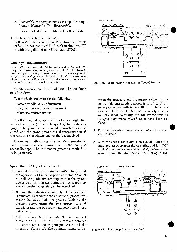
c. Reassemble the components as in steps 4 through 6 under Hydraulic Unit Reassembly.
Wote: Each shaft must rotate freely without binds.
4. Replace the other components. Follow steps l a through l c of Procedure 2 in reverse order. Do not put used fluid back in the unit. Fill it with one gallon of new fluid (part 477567).
Carriage Adg'ustrnents .Vote: All adjustments should be made with a hot unit. To judge the correct temperature, check a unit that has been in use for a period of eight hours or more. For servicing, rapid temperature buildup can be obtained by blocking the hydraulic blower air intake with a card, and running in gear at high speed with covers closed for about 15 minutes.
All adjustments should be made with the shift knob in 6-line drive.
Two methods are given for the following:
Bypass needle-valve adjustment Single-space single-shot adjustment Magnetic emitter timing
The first method consists of drawing a straight line across the paper (while it is spacing) to produce a graph. The pencil must move at a constant rate of speed, and the graph gives a visual representation of the results of the adjustments or timings involved.
The second method uses a tachometer-generator to produce a more accurate visual trace on the screen of an oscilloscope. The tachometer-generator method is to be preferred.
Add or remove shim--]
Figure 44. Space Magnet Armature in Neutral Position
tween the armature and the magnets when in the neutral (de-energized) position is .Oil" to .013". Some spool-valve units have a .011" to .014" clear- ance, which is correct. The spool-valve adjustments are not critical. Normally, this adjustment must be changed only when related parts have been re- placed.
4. Turn on the system power and energize the space- @ stop magnets.
5. With the space-stop magnet energized, adjust the back stop screw nearest the operating rod for .005" to .008" clearance (preferably ,005") between the armature and the stop-magnet cores (Figure 45).
Spas@ @ontr@~-hifhgne~ Adjustnaemt r. 005" to .008" rAdjurting Screw
1. Turn off the printer mainline switch to prevent the operation of the carriage-drive motor. Some of the following adjustments require that the system power be on so that the hydraulic-unit space-start and space-stop magnets can be energized.
2. Remove the valve-body assembly. If the reservoir is removed, to facilitate the adjustment procedures, mount the valve body temporarily back on the channel plates using the two upper holes of &e i a t e s and the two lower (tapped) holes in the "~alve body.
3. Add ar 7emoi.e the shims under the pivot support i o c k to obtair, .G11" to .013" clearance between ":-, .IL, c ~;iart.t-magxelet and siop-magnet cores and the
1 7 .
arr2,ature ,\.::qac- 44''. The optimum ciearance be- ~i~~~~ 45. Space Siop &fagnet Energized

Adjusting Screw-
Figure 47. Space Valve in Start Position
Figure 46. Space Start Magnet Energized 3. Turn on the system power.
6. Turn off the system power.
7. Energize the space-start magnets.
a. Remove the wires from the space-stop magnet terminals and insert them into the space-start magnet terminals.
b. Turn on the system power.
8. With the space-start magnet energized, adjust the backstop farthest from the operating rod for .005" to .008" clearance (preferably .005") between the armature and the start-magnet cores (Figure 46).
Note: If it is objectionable to use a steel feeler gage in the preceding steps because of the attraction of the energized control magnets, use a data processing card to obtain these adjustments.
9. Slow operation will result from a clearance of less than .005". There are no residuals on the armatures or cores.
10. Turn off the system power.
11. Whenever this adjustment has been made, the space-control-valve adjustments must be checked.
1. Adjust the space-control magnets.
2. Be sure that at least half of the lower threaded por- tion of the operating rod is screwed into the control valve and that the locking nut at the upper end of the control valve is tight.
0 Note: It is imperative that no scratches or marks or slight bends of any kind be made on the operating rod. These would lead to failure.
4. With the space-start-magnet energized, adjust the nuts at the top of the operating rod for .009" to .011" clearance between the top of the valve and the top surface of the rectangular port in the valve body (Figure 47).
a. This should result in .009" to .015" clearance between the bottom of the valve and the lower surface of the rectangular port with the stop - - magnet energized and the armature in the stop position (Figure 48).
b. The optimum adjustments of the .011" to .013" clearance and the .005" to .008" clearance for the control magnets result in a .020" to .024" control valve travel.
Note: It is not necessary to readjust the .011" to .013" set at the factory unless related parts are replaced.
Figure 48. Space Valve in Stop Position
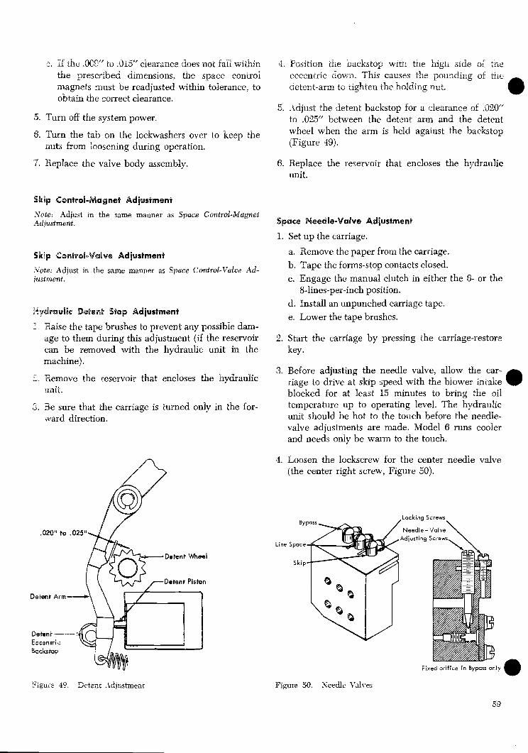
3. 7E the .OOY to .015" cjearance does not fail within
a the prescribeci dimensions. ths space control magnets must be readjusted within tolerance, to obtain the correct clearancs.
5. Turn off the system power.
6. Turn the tab on the lockwashers over to keep the nuts from loosening during operation.
7. Replace the valve body assembly.
Skip Control-Magnet Adjustment
Note: Adjust in the same manner as Space Control-Magnet Adjustment.
Skip Control-Valve Adjustment
;Vote: Adjust in the same manner as Space Control-Value Ad- just rnent.
Hydrauiie Datent Stop Adjustment
1. Raise the tape brushes to prevent any possible dam- age to them during this adjustment (if the reservoir can be removed with the hydraulic unit in the machine).
2. Remove the reservoir that encloses the hydraulic unit.
3. Be sure that the carriage is turned only in the for- ward direction.
Figure 49. Setenc A\djustmenr
4. Positio~l the ~ackstop wlrr, tne high side of :iiz rT- eccentric dovia. I his causes the pounding of m e
detent-arm to tighten the holding nut.
5. Adjust the detent backstop for a clearance of .320" to .035" between the detent mm and the detent wheel when the arm is held against the backstop (Figure 49).
6. Replace the reservoir that encloses the hydraulic unit.
Space Needle-Valve Adjustment
1. Set up the carriage.
a. Remove the paper from the carriage. b, Tape the forms-stop contacts closed. c. Engage the manual clutch in either the 6- or the
8-lines-per-inch position. d. Install an unpunched carriage tape. e. Lower the tape brushes.
2. Start the carriage by pressing the carriage-restore key.
3. Before adjusting the needle valve, allow the car- riage to drive at s h p speed with the biower intake blocked for at least 15 minutes to bring the oil
a temperature up to operating level. The hydraulic unit should be hot to the touch before the needle- valve adjustments are made. Model 6 runs cooler and needs only be warm to the touch.
4. Loosen the lockscrew for the center needle valve (the center right screw, Figure 50).
Lockina Screws
Line
Figure 50. Keedle Valves
Fixed orifice in Bypass only

5, Adjust the needle valve to cause .the detent io nip -
a as follows:
a. Hold the screwdriver against the detent arm at -
the notch. b. Back off on the center left screw (Figure 50)
until you feel the detent nip the detent wheel. The impact will be transmitted through the screwdriver.
6. Adjust the needle valve to stop the detent from nipping.
a. From the nip condition, close the needle valve only far enough to bring the detent to rest against the backstop. Following this, you should still feel hydraulic-pump vibration when placing your finger on the tail of the detent.
70. Tighten the lockscrew (the center right screw).
7. After this adjustment has been made, the skip needle valve must be adjusted.
3ila Needle-Valve Adjustment f -Speed Carriage Machines)
.core: Licdel 6 Printers are single-speed machines. In carriages oil Sfodel 6 ~rinters. the adjusting screw on the ski^ needle , u
a;\ e jnou!cl be iully closed and lociced.
1 Tie ipacs needle valve must be adjusted.
3. Zet up the carriage. Make sure:
a. There is no paper in the carriage. b. The forms-stop contacts are closed. c. The manual clutch is engaged. d. Unpunched carriage tape is installed. n. The ;ape brushes are lowered.
3. Start tile sarriage in a programmed skip-to-1 before 9rht . This should result in a skip-to-l at high speed. with no stop impulse available.
4. Loosen the lockscrew for the skip needle valve (the front right screw, Figure 50).
5. Adjust the skip needle valve as follows:
a. Hold a screwdriver against the detent arm at .the notch.
b. Back off on the froni left screw (Figure 50) uitil you feel the detent nip -the detent wheel. The impact will be irailsmitted though the screwdriver.
(1) If no nipping is detected d te r turning out a maxi- mum of five turns, stop the carriage motor so that the
0 hydraulic pumps ar.e not moving. Turn down on the front Beit screw mti l it is closed. Then back ~ f f 6ve turns on h i s screw. Tighten the !ockscrew (the front right screw).
(2) If nipping is detected, adjust the needle valve .io stop the detent from nipping.
c. From the nip condition, close the needle valve a only far enough to bring the detent to rest against the backstop. Following ihis, you should still feel hydraulic-pump vibration when placing your finger on the tail of the detent.
d. Tighten the lockscrew (the front screw). Stop the carriage.
e. After this adjustment has been made, the bypass needle valve must be adjusted.
Bypass Needle-Valve Adjustment (Using Pencil Trace)
1. The following should be adjusted:
a. The space needle valve. b. The skip needle valve (on machines with the
2-speed carriage).
2. Be sure :hat the following adjustments are correct:
a. The tractors. b. The tractor drive shafts.
3. The E-l emitter and circuits controlling triple- space must be adjusted su%ciently to provide con- sistenc triple-spaces when the detent is held dis- engaged.
4. Set up the carriage.
a. Place the paper in the carriage. b. Program for triple space. c. Engage the manual clutch in the 6-lines-per-
inch position. d. Remove the upper front paper guides.
5. Lcosen the lockscrew for the 5ypass needle valve (the rear right screw, Figure 50).
8. Tilrn in on the 'bypass needle valve (rew left screw) until it is dosed, then turn it out '/z imn.
4. Disengage h e deient a m by pressing dswn 4n the notch wlih a large screwdriver.
8. Start the carriage by pressing the start key.
9. Adjust the bypass needle valve as Sollows:
a. Draw line graphs across the papzr while it is feeding.
(1) Move the pencil ai a rate that wili shcw iro-o.~ :our :o ten triple spaces on a sheet 11" wide.
( 2 ) T 2 ~ o much ~ e n c i l pressure can cause a drag on %;he ?a?er, and :herehe, an erroneous graph.

Figure 53. Single-space Single-Shot Adjusted Correctly
Figure 51. Bypass Adjusted too Tight (Hydraulic Bounce) c. Check that the manual clutch is in 6 lines-per-
inch drive position.
d. Program for single space. (3) With the needle valve adjusted too tight (as in step 6) the resulting graph will be similar to Figure 51. 3, Start the carriage by pressing the start key.
b. Turn out on the bypass needle valve until the line graph just resembles Figure 52.
c. Tighten the lockscrew (the rear right screw), and recheck the pencil trace.
10. Stop the machine.
11. After this adjustment has been made, the follow- ing must be adjusted:
a. The sing'le-space single shot. b. The 33-1 emitter. c. The tape-drive sprocket and the carriage
brushes.
Single-Space SieogBe-Shot Adg'ustment (Using Peweil Brae@)
4. Draw line graphs on the paper while it is feeding.
5. Adjust the single-space single-shot within the sys- tem to produce the desired result. The resulting graph should be similar to Figure 53.
Magrretie Emitter Adjustment
Current production 1403 printers have a magnetic emitter that replaces the former E l emitter brush. The adjustments are as follows:
1. The emitter wheel should be .01(Y' to .020" from the nylon bushing as shown in Figure 54.
1. Be sure '&at no binds exist when you manually turn the forms-advance knob with the 6-8 h o b in neu- tra'l.
2. Set up the carriage.
a. Check that paper is in the carriage. b. Check that the upper front paper guides ape
removed.
Transducer Assembly
a Emitter Adjusting Arm
0 Adjusting Block Emitter Arm Spring
-. 2 ;grre 52. S!?ZSS -4djusieC Z s r s ~ t l y Figure 54. Z-1 Magnetic Emitter

2. Loosen the bansaucer damp screw, and adjust the transducer for .008" clearance to the emitter wheel. Figure 54 shows the ~ansducer air gap.
Note: This adjustment can be varied to a minimum of .002" to meet the specified transducer output of 2 to 4.5 volts peak-to-peak and 3n E l pulse duration of 1.1 to 1.5 ms at low speed.
3. Adjust the emitter output.
a. Disconnect the black and white leads from the transducer to terminals 8 and 9 of the amplifier card.
Caution: Turn power off when removing or replacing the leads. If certain terminals are grounded, the amplifier- card components may be damaged.
b. Connect the white lead from the transducer to the scope probe and the black lead to the scope ground.
c. With the emitter wheel operating continuously at low speed, the waveform must appear as shown in Figure 55 with an output of 2 to 4.5 volts peak-to-peak. Refer to step 2.
Note: To operate continuously at low speed, remove the #1 carriage stop-brush wire or use a blank carriage tape, and press the restore key.
4. If the observed wavefom appears as shown in Figure 55, reconnect the white lead to terminal 8, and the black lead to terminal 9. If, however, the waveform has a rapid rise to the positive pulse and a slow drop to the negative pulse, reverse the leads when reconnecting them to the terminal block.
5. With all leads connected and the emitter wheel operating continuously at low speed, check the am- plified output at the E l sync point or terminal 1 on the amplifier card for:
a. -8V minimum (normally -12V). b. 1.1 to 1.5 ms duration. c. 2 to 30 microseconds rise time. d. 1 to 30 microseconds fall time.
Magnetic Emitter Timing (Using Pencil Trace)
This adjustment is for Models 1 and 2 only. Adylst the emitter-adjusting arm (see Figure 54). Timing should
be adjusted to obtain the least time to settle tractor- shaft movement. Compromise between triple-space wit5 6 lines per inch and double-s~ace with 8 lines per inch.
I. Be sure that no binds exist when you manually turn the forms-advance knob with the 6-8 knob in neu- ~ a l .
2. Set up the carriage. a. Check that the paper is in the carriage. b. Check that the upper front paper guides are re-
moved. c. Check that the manual clutch is in 6 lines-per-
inch drive position. d. Program for triple space.
3. Start the carriage by pressing the start key.
4. Draw line graphs on the paper.
5. Shift the emitter adjusting a m until the line graph appears as shown in Figure 56. a. There may be a siight overshoot (maximum al-
lowable Xi') on these graphs. b. Some overshoot may be necessary on triple-space
6 lines-per-inch to prevent excessive pull-in on double-space 8 lines-per-inch.
6. Check the adjusting-arm setting for double-space. a. Set the manual clutch to 8 lines-per-inch drive
position. b. Program for double-space. - - c. Start the carriage and draw line graphs..
Indicates E - l Emitter Out of Adjustment
Misadjustment of E - l Emitter r Can couse either 1
OVERSHOOT UNDERSHOOT (Pull-in)
Figure 55. E-1 Magnetic Emitter Waveform
62
Figurz 56. Z-1 Emitter Adjusted CorrecGy

7. Readiust the adjusting-arm as required for the best b. Some overshoot may be necessary on triple-space line graph of:
-
a. Double-space 8 lines per inch. b. Triple-space 6 lines per inch.
8. After this adjustment has been made, adjust the tape-drive sprocket and the carriage brushes.
Emitter-Brush Timing (Using Pencil Trace)
1. Be sure that no binds exist when you manually turn the forms-advance knob with the 6-8 knob in neu- tral.
2. Set the emitter brushes in the brush holder for a projection beyond the brush holder of YZ" (f X4").
3. Set up the carriage.
a. Check that the paper is in the carriage. b. Check that the upper front paper guides are re-
moved. c. Check that the manual clutch is in 6 lines-per-
inch drive position. d. Program for triple-space.
4. Start the carriage by pressing the start key.
5. Draw line graphs on the paper.
6. Shift the brush assembly until the line graph ap- pears as shown in Figure 56.
a. There may be a slight overshoot (maximum d- lowable Xi') on these graphs.
6 lines-per-inch to prevent excessive pull-in on double-space 8 lines-per-inch. e
7. Check the brush setting for double-space.
a. Set the manual clutch to 8 lines-per-inch drive position.
b. Program for double-space. c. Start the carriage and draw line graphs.
8. Readjust the brush assembly as required for the best line graph of:
a. Double-space 8 lines per inch. b. Triple-space 6 lines per inch.
9. After this adjustment has been made, adjust the tape-drive sprocket and the carriage brushes.
Carriage Adjustment with the Tachometer-Generator The tach-generator (Figure 57) converts the mechan- ical motion of the carriage into an electrical output for scoping. This is an extremely accurate method of adjusting and analyzing the hydraulic unit. If adjust- ing by the methods of the previous section does not correct faulty carriage operation, use the tach- generator.
Before using the tach-generator, check the adjust- ments of the space and skip needle valves. The forms tractor and upper and lower drive shafts must also be correctly adjusted. The tractor shaft relationship is cor-
Upper Tractor Drive - Shaft Assembly
.
. \
Hydraulic Co~p l i ng
Tach -Generator
Figure 57. Tach-Generztor and Coupling

rect when the upper tractor pins touch the top edge the space-stop magnet (terminal 2, resistor 3) as the of the paper holes while the bottom tractor pins touch second input to the scope. On single-input scopes,
@ the bottom edge of the paper holes. Slight elongation two signals can be examined separately in relation of the holes under power is permissible. to the start-magnet impulse.
Tach-Generator and Scope Connections
Note: -4 defective capacitor or one of incorrect rating alters the tach-generator output trace on the scope. The capacitor should remove high-frequency oscillation from the scope trace without affecting pulse timing. Check by ob-
1. Connect a 1.0 mfd, 200V capacitor (part 253826) serving pulse timing with the capacitor in and out of the across the tach-generator output terminals.
2. Remove the paper-advance h o b from the upper tractor drive shaft. Install the tach-generator (part 450976) and coupling (part 451290) on the shaft as shown in Figure 57 and tighten the setscrew.
3. Ground the scope and connect the vertical input and the scope ground to the tach-generator term- inals.
4. Sync the scope on the impulse to the space-start magnet (terminal 2, resistor 4, logic page 02.01.1). If a dual-input scope is available, use the impulse to
Bypass Adjusted Too Loose (1/4 Turn)
N o Hydraulic
Li
- - - circuit.
Bypass Needle-Valve Adjustment (Using Tach-Generator)
Before proceeding, the hydraulic unit must be hot enough to be uncomfortable to the touch. The Model 6 runs cooler and needs only be warm to the touch.
1. Set up a program for a triple-space loop at 6 lines per inch with blanks in the print area.
2. Engage the manual clutch in the 6 lines-per-inch position.
Stop
Bypass Adjusted Correctly
? o w s Triple Space
,H;,jrculic Stop
,,Carriage Dr i f t
Bypass Adjusted Too Tight (1/4Turn)
I +
Heavy Hydraulic Bounce
(2V/CM) (5MS/CM)
Figure 58. Bypass Needle Valve Adjustment
84

3. Loosen the bypass needle-valve lock screw just of relatively square corners followed by carriage enough to permit adjusting the needle valve. drift verifies correct bypass adjustment. Observe - -
4. Disengage the detent arm by pressing down in the tllat as little as !4 tu rn from the correct setting for
notch with a large screwdriver. the bypass needle valve can produce incorrect scope and line graphs.
5. Block the forms switches and run the printer pro- gram.
6. Observe the scope and adjust the bypass needle valve to obtain the scope trace shown in Figure 58. Tighten the lockscrew, and recheck the scope pic- ture and pencil trace (step 7).
7. You can double-check the adjustment by making a line graph. Figure 58 shows the scope picture and line graph for the same conditions. A scope trace indicating light hydraulic bounce and a line graph
Single-Shots
Three different single-shots are used to stop the car- riage motion after space operations. Single-space single-shots are used on klodels 1, 2, 3, 4, 5, and 6. Double-space and triple-space single-shots are used on klodels 3, 4, 5, and 6, when used with a system for which they were originally designed. Refer to Figure 59. Be sure to check the adjustment of the magnetic
Table I. 1403 Carriage Single -Space Timings in Milliseconds
I @ After -Space Print - Delay Single - Shot I l6
1 @ The actual setting may w r y for optimum carriage operation.
1 Model 1
Carriage Interlock Time
@ Fwms Interlock Single -Shot
@ The actual setting w i l l be the difference between the carriage -interlock time and the actual setting of the single -space single -shot.
a System for which each model was originally IBM 1401-G IBM 1401-G IBM 1401 - G designed to operate.
@ The actual setting w i l l be 1.7ms ( 1.1 rns on the Model 3) less than the actual setting of the after -space print -delay single -shot.
Model 2
@ Single - Space Single - Shot
Notes: @ These timings are valid only when a porticular model printer is used with the system for which it was originally designed. For other printer-system combinations, refer to the manual for the system for correct timings.
21.4
10
- - -
Table 2. Miscellaneous Information
I Number of Print Positions
Model 3
4.5
21.4
10
1 Maximum Printing Speed (LPM) 1 ( 1100 1 465 1 465 1 340 1 Choin/Train Motw Speed (RPM) 3600 3600 3600 3600
, ChainjTrain Velocity (IPS) 90.3 90.3 206 67.73 67.73 51.93
Model 4 Model 5 -----
4.5
20.8
14
Model 6
I Timing Disk Speed (RPM)
5.5
22.5
14
1 Time Required for Type to Move .001" 11.1 1 1 . 1 14.8 14.8 19.25 (Microseconds)
Time of Carriage Start Impulse
Setting far Calibrotion of Print - Timing Dial with Print Density Lever Set at C.
I Print SS- l of Print SS- l of i Print SS- I of P r 3 of Print SS-3 of Print SS-3 of / Print Scan 48 Print Scan 48 / Print Scan 46 Print Scan 48 Print Scan 48 Print Scan 48
5.5
22.5
14
Time Required to Print C)ne Line (with Single Space )
34.5
27
20
54.54ms. 129m. 129 ms. 176.5ms.
5.5
Timings for the Model 3 .with PCS are ihe some as for the Model 3, except for maximum printing v e d , which is 1400 i Ipm ) and the time of carriage start impulse, which i s rhe beginning of PSS - 1 of Print Scan 46, or when printing is finished.
Figure 39. Reference Chart (mhr 1403)
5.5
20 Has no dial 15 15 11

emitter if the double- or triple-space single shots are adjusted. Before proceeding with the adjustments, ob- serve the following:
1. Be sure no binds exist when you manually turn the forms advance knob with the 6-8 line knob in neutral.
2. Check that paper is in the carriage.
r Spoce Stort Impulse (See Toble 2, Figure 59)
I Single - Space Single - Shot Times O u t Space Stop Impulsed Start Af ter - Space Print- Delay (16 m s ) SS
I I (Refer to Toble 1, Figure 59, for timings)
After - Space Print - Delay SS Times O u t N e x t PSS Pulse Starts Print Scan 1 o f Nex t Line
Carriage Interlock Time
Single Shot Set at 4.6
e Heovy Pull-In; 24 Milliseconds Totol Time from Spoce Stort Signal unt i l Troctor Shoft Movement Is Stopped
Single Shot Set a t 6.0
Nearly Square Corner; 17 Milliseconds Totol Time from Space Stort Signal unti l Troctor Shoft Movement Is Stopped
Single Shot Set at 6.8
Heovy Overshoot; 30 Milliseconds Totol Time from Spoce Stort Signol unti l Troctor Shoft Movement Is Stopped
Single-Space Single-Shot Adjustment (Using Tach-Generator)
Note: These timings are valid only when the particular printer model indicated is used with a system for which it was originally designed. If the printer is used with any other system, refer to the system specifications for the correct timings (Figure 59).
These adjustments are made in the system to pro- duce the desired result in the IBM 1403 Printer.
1. Set up a program for a single-space loop at 6 lines per inch.
Space Start lmpulse (See Table 2, Figure 59) (3rd PSS Pulse of Print Scan 48) Stort 5 . 5 Millisecond Single-Shot
I r 5.5 m s S S Times Out - Space Stop Impulsed Stort 29 Millisecond Single - Shot
29 Millisecond Single - Shot Times Out Next PSS Starts Print Scan 1 of Next Line
Single Shot Set at 4.6
Heovy Pull-In; 24 Milliseconds Totol Time from Space Start Signal until Tractor Shaft Movement Is Stopped
Single Shot Set at 6.0
Nearly Square Corner; 17 Milliseconds Total Time from Space Start Signal until Tractor Shoft Movement Is Stopped
Single Shot Set at 6.8
Heavy Ovenhoot; 30 Milliseconds Total Time from Spoce Stori Signal until Troctor Shoft Movement Is Stopped
Figure 60. Single-Space Single-Shot Adjustment (Models 1, 2, 3, 4, and 5) Figure 61. Single-space Single-Shot Adjustment (Model 6)

2. Initially set the after-space print delay single-shot to: a. 16 ms on Models 1, 2, 3, 4, and 5. b. 29 ms on Model 6.
3. Adjust the single-space single-shot for minimum time from the start of trace (carriage space-start im- pulse) until the scope pattern indicates the tractor- shaft movement is stabilized (Figure 60 for Models 1-5, Figure 61 for Model 6).
4. Observe the timing of the single-space single-shot and adjust the after-space print delay single-shot so that the total of the two timings equals: a. 21.4 ms on Models 1 and 2, b. 20.8 ms on Model 3, c. 22.5 ms on Models 4 and 5, d. 34.5 ms on Model 6.
The end of the after-space print-delay single-shot trace should be measured at the midpoint of the negative-going pulse.
Note: This single-shot can be set most accurately by syncing on the start of the single-space single-shot and adjusting the after-space print delay single-shot to time out 21.4 ms later on Models 1 and 2, 20.8 ms later on Model 3; 22.5 ms later oil Models 1 and 5: 34.5 ms later on Model 6.
5. Observe the timing of the single-space single-shot and adjust the forms interlock single-shot so that the total of the two timings equals: a. 19.7 ms for Models 1, 2, and 3, b. 20.8 ms for Models 4 and 5, c. 32.8 ms for Model 6.
Note: The forms interlock single-shot can be set most accurately by syncing on the start of the single-space single- shot and adjusting the forms interlock single-shot to time out 19.7 ms later on Models 1, 2, 3; 20.8 ms later on Models 4, 5; 32.8 ms later on Model 6.
6. Record the settings of each single-shot on the appro- priate system logic for future reference.
Double-Space Single-Shot Adjustments (Models 3, 4, 5, and 6.)
1. Check that the manual clutch is in 8 lines-per-inch drive position.
2. Program for double-space after print only.
3. Start the carriage by pressing the start key.
4. Adjust the double-space (9.8 ms) single shot for minimum stabilization time. The pencil trace or scope pictures should be similar to those in Figures 56, 64, and 65.
5. Set the manual clutch to 6 lines-per-inch and repeat the observation of the pencil trace or scope picture.
6. The final adjustment of the double-space single-shot is for the best compromise between minimum over-
shoot at 6 lines-per-inch, and minimum pull-in at 8 lines-per-inch. (This is also a compromise for the minimum time from the impulse of the space stop magnet until the tractor shafts are settled down.)
Triple-Space Single-Shot Adjustment (Models 3, 4, 5, and 6.)
1. Set the manual clutch to 6 lines-per-inch.
2. Program for triple-space (after print only).
3. Start the carriage by pressing the start key.
4. Adjust the triple-space (13.8 ms) single shot to pro- duce a proper pencil trace or minimum stabilization time as shown by a tach-generator on a scope. Refer to Figures 62 and 63. See also Figure 56.
Space Start lmpulse (See Table 2, Figure 59)
Space Stop Impulse- (E-l Emitter Controlled on Models 1 and 2) Starts Timing Out (Triple- Space SS Controlled on Models 3,4, and5) After - Space Print - Delay (16 Mil l isecond) Single - Shot
I
After - Space Print - Delay Single - Shot Times Out Printing Can Begin wi th Next PSS Pulse
1 1 4
El or Triple-Space Single-Sat Set Early
Trace Shows Pul I-In 19 M i l l ireconds from Stop Impulse unti l Tractor Shaft Is Settled
El or Triple-Space Single-Shot Set Correctly
8 Milliseccnds from Stop Impulse unt i l Tractor Shaft Is Settled
El or Triple-Spoce Single-Shot Set Late
Troce Shows Overshoot 23 Milliseconds from Stop Impulse unti l Tractor Shaft I s Settled
(2V~'ch') (5MS 'CM)
Figure 62. E-1 Emitter or Triple-Space Single-Shot Adjust- ments for Triple-spacing at 6 Lines per Inch (Models 1, 2, 3, 4, and 5)

Space Start Impulse (See Table 2, Figure 59)
Space Stop Impulse - (Triple - Space Single - Shot Controlled ) Storts Timing Out 29 Millisecond Single - Shot I I
29 Mil l isecond Single - Shot Times Out - Printing Can Begin wi th Next PSS Pulse
Triple-Space Single-Shot Set Eclrly
Trace Shows Pull-In 19 Milliseconds from Stop Impulse unt i l Tractor Shaft Is Settled
Triple-Space Single-Shot Set Correctly
8 Milliseconds from 5rop Impulse unti l 'roctor Shaft Is Settled
Triple-Space Single-Shot Set Late
Troce Shows Overshoot 23 Milliseconds +om Stop lmpulse unt i l Troctor Shaft Is Settled
1. Program for double-space (after print only).
2 . Sync the scope on the impulse to the space-start magnet.
3. Observe the time that the double-space single shot times out.
4. Display the magnetic emitter impulse.
5. Adjust the emitter timing so an emitter pulse starts at the same time the double-space single shot times out.
6. Program for triple-space (after print only).
7. Observe the time that the triple-space single shot times out. The magnetic emitter impulse for the 3-line skip should occur at the same time.
8. The final emitter timing is a compromise to provide emitter pulses timed as closely as possible to the time-out of both the double-space and triple-space single shots.
9. Adjust the carriage tape sprocket so the stop brushes make 1.5 (+.25, -0) milliseconds before the emitter pulse.
Note: All other carriage tape-brush adjustments should be made before the timing adjustment is made. The expected oscilloscope traces for skipping are shown in Figure 66. This figure does not apply to the Model 6, which has no high- speed skip function.
Magnetic Emitter Timing (Using Tach-Generator)
Note: This procedure is for Models 1 and 2 printers used with 1401 system. For printers used with other systems, refer to systems manuals for timings.
1. Make sure the emitter is in correct adjustment as Figure 53. Triple-space Single-Shot Adjustments for Triple- described under Magnetic Emitter Adjustment.
Spacing at 6 Lines per Inch (Model 6 Only) Then, set up the tach-generator and oscilloscope.
2. Set up a program for a triple-space loop at 6 lines 5. Set the manual clutch to 8 lines-per-inch and re- per inch.
peat the check by the line trace or tach-generator 3. Iiun the program and observe the scope trace. method. .
4. Shift the emiiter adjusting arm to obtain the least 5. The final adjustment of the triple-space single shot
time for the tractor shaft to stabilize. Figure 62 is a compromise between minimum overshoot at 6
shows the way the trace should look. lines-per-inch and minimum pull-in at 8 lines-per- inch. (This is also a com~romise for the minimum Note: Usin% the line-graph method may indicate over-
time from the impulse of the space-stop magnet un- shoot, pull-in, or squareiess, but the best print alignment occurs when the requirement of step 4 is met. The emitter
ti1 the tractor shafts are settled down.) can also be rotated with res~ec t to the shaft to adiust emitter timing.
~~Aagneri.; Emitter Timing (Models 3. 4, 5. and s.) 5. Change the program to a double-space loop at 8 lines per iiich.
The space single shots must be correctly adjusted Ce- fore adjusting the magnetic emitter timing. 8. Run the pogranl and observe the scope trace.

Space Stort Impulse (See Table 2 , Figure 59) Space Start Impulse (See Table 2, Figure 59)
Spoce Stop lmpulse - (E-l Emitter Controlled on Models 1 a d 2 ) Stork Timing Out (Double-Space S S Controlled on Models 3, 4, and 5)
After-Space Print-Delay (16 Millisecond) Single-Shot I After-Space Print-Delay (16 ms) Single-Shot Times Out Printing Con Begin with Next PSS Pulse I I
El or huble-Spoce Single-Shot Set to Best Condition
12 Milliseconds from Stop Impulse until Troctor Shaft Is Settled
El or Double-Space Single-hot Set Early
19 Milliseconds from Stop lmpulse until Tractor Shaft Is Settled
Figure 64. E-1 Emitter or Double-Space Single-Shot Adjust- ments for Double-Spacing at 8 Lines per Inch (Models 1, 2, 3, 4, and 5)
7. Shift the emitter adjusting arm to obtain minimum time for the tractor shaft to stabilize (Figure 64).
Note: For the final setting of the emitter adjusting arm, it may be necesary to compromise between the adjustment at triple space 6 lines per inch and double space 8 lines per inch.
8. After completing the tach-generator carriage adjust- ments, adjust the tape drive sprocket so the car- riage-tape brushes make 1.5 (+ .25, - 0) millisec- onds before the emitter makes. The expected scope traces for skipping are shown in Figure 66. All other carriage tape-brush adjustments should be made before the timing adjustment is made.
Emitter Brush Timing (Using Tach-Generator)
1. Set the emitter brushes for %" (* W ) projection beyond the brush holder.
2. Set up a program for a triple-space loop at 6 lines per inch.
3. Run the program and observe the scope trace.
4. Shift the ernitter-brush holder to obtain the least time for the tractor shaft to stabilize (refer to Fig- ure 62).
Space Stap lmpulse (Dauble-Space SS Controlled) - Starts Timing O u t 29 Mill isecond Single-Shot
29 Mill isecond Single Shot Times O u t - Printing Can Begin with N e x t PSS Pulse
I
Double-Space Single-Shot Set t o Best Condition
12 Milliseconds from Stop Impulse unt i l Tractor Shaft Is Settled
Double-Space Single-Shot Set Early
19 Milliseconds from Stop lmpulse unt i l Tractor Shaft Is Settled
(2V/CMJ (5MS/CM)
Figure 65. Double-Space Single-Shot Adjustments for Double- Spacing at 8 Lines per Inch (Model 6 Only)
Note: Using the line-graph method may indicate over- shoot, pull-in, or squareness, but the best print alignment occurs when the requirement of step 4 is met. The emitter can also be rotated with respect to the shaft to adjust emitter timing.
5. Change the program to a double-space loop at 8 lines per inch.
6. Run the program and observe the scope trace.
7. Shift the emitter-brush holder to obtain minimum time for the tractor shaft to stabilize (Figure 64).
Note: For the final setting of the emitter-brush holder, it may be necessary to compromise between the adjustment at triple space 6 lines per inch and double space 8 lines per inch.
8. After completing the tach-generator carriage adjust- ments, adjust the tape drive sprocket so the car- riage-tape brushes make I (+ %, - 0) millisecond before the emitter brush makes. The expected scope traces for skipping are shown in Figure 66. All other carriage tape-brush adjustments should be made before the timing adjustment is made.
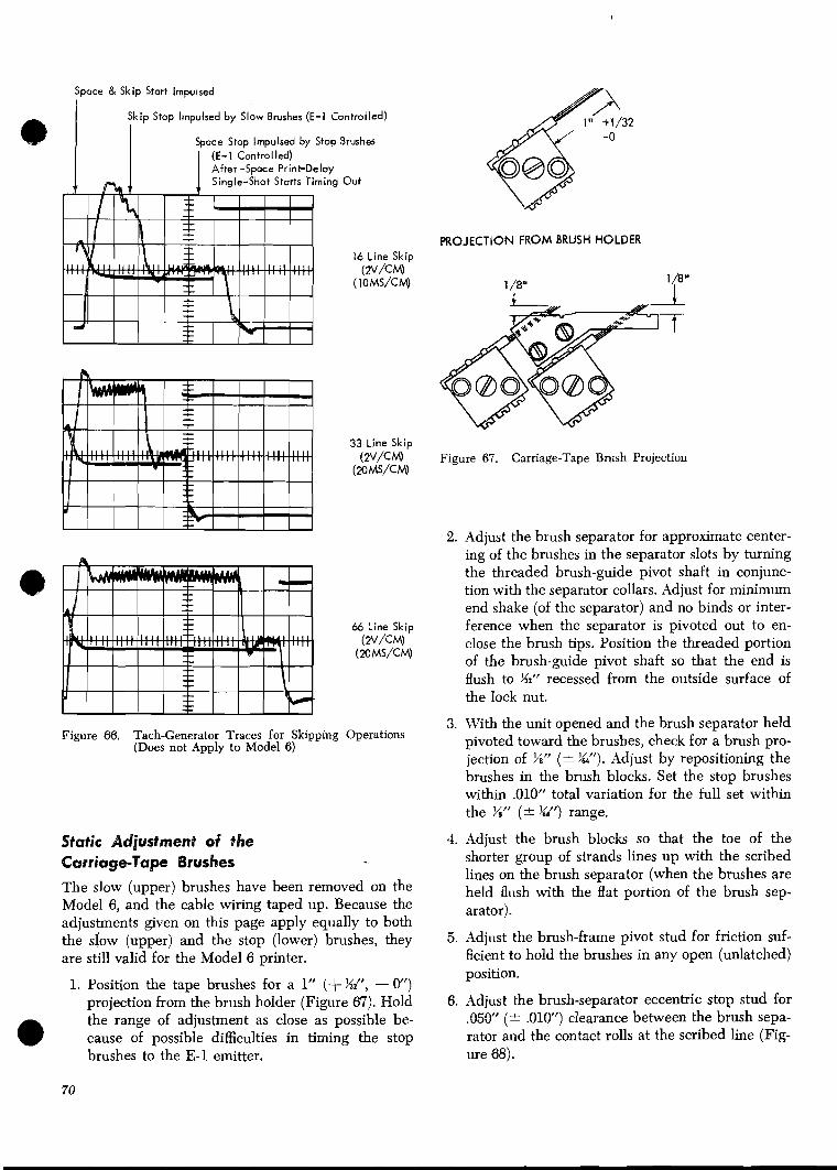
Space & Skip Start Impulsed
Skip Stop Impulsed by Slow Brushes (E-1 Controlled) I
Space Stop Impulsed by Stop Brushes I ( I -1 Controlled) After -Space Print-Deloy
Out
16 Line Skip (N/CM)
(IOMS/CM)
33 Line Skip (PV/CM)
(20MS/CM)
66 Line Skip (2V/cM)
(MMS/CM)
Figure 66. Tach-Generator Traces for Skipping Operations (Does not Apply to Model 6)
Static Adjustment of #Re Carriage-Tape Brushes
The slow (upper) brushes have been removed on the Model 6, and the cable wiring taped up. Because the adjustments given on this page apply equally to both the siow (upper) and the stop (lower) brushes, they are still valid for the Model 6 printer.
1. Position the tape brushes for a 1" (+ %", - 0") projection from the brush holder (Figure 67). Hold the range of adjustment as close as possible be-
@ cause of possible difficulties in timing the stop brushes to the E-1 emitter.
PROJECTION FROM BRUSH HOLDER
Figure 67. Carriage-Tape Bntsh Projection
2. Adjust the brush separator for approximate center- ing of the brushes in the separator slots by turning the threaded brush-guide pivot shaft in conjunc- tion with the separator collars. Adjust for minimum end shake (of the separator) and no binds or inter- ference when the separator is pivoted out to en- close the brush tips. Position the threaded portion of the brush-guide pivot shaft so that the end is flush to K" recessed from the outside surface of the lock nut.
3. With the unit opened and the brush separator held ~ ivo ted toward the brushes, check for a brush pro- jection of %" (* &'). Adjust by repositioning the brushes in the brush blocks. Set the stop brushes within .010" total variation for the full set within the %" (1 %Lf) range.
4. Adjust the brush blocks so that the toe of the shorter group of strands lines up with the scribed lines on the brush separator (when the brushes are held flush with the flat portion of the brush sep- arator).
5. Adjust the brush-frame pivot stud for friction suf- ficient to hold the brushes in any open (unlatched) position.
6. Adjust the brush-separator eccentric stop stud for .050" (5 .010") clearance between the brush sepa- rator and the contact rolls at the scribed line (Fig- ure 68).

B' Pivot
Eccentric Stop Stud
P-' ~ a t c h Lever .00lU to .006" With Brush Assembly Held
Latch Block Down Al l the Way
2 Latch Lever
Figure 68. Carriage-Tape Brush Assembly Adjustments
11. Adjust the brush-interlock-switch actuator so that the switch transfers before the latch pawl fully disengages the latch block. Adjust for minimum end shake with no binds.
12. After these adjustments have been made, adjust the carriage-tape brushes dynamically. Caution: Be sure the stop rod is located so that it will not contact the raised hub of the contact roll. Blown fuses could result.
Dynamic Adjustment of the Carriage-Tape Brushes 1. Be sure that no binds exist when you manually turn
the forms-advance knob with the 6-8 knob in neutral.
2. Set up the carriage for dynamic adjustment.
a. Insert a carriage tape with a channel 1 punch on every third line.
Note: Use a tape punched with the customer's tape punch.
b. Remove the forms. c. Engage the manual clutch in 6-line drive. d. Program a space to zero (no numeric bits) before
print.
3. Set up the scope for: 7. Adjust the latch block to obtain .001" to ,006''
clearance between the latch pawl and latch block a. 1 millisecond/division horizon tall^. with the brush assembly fully depressed (Figure b. lOV/division vertically. 68). c. Sync on negative shift of stop brush at the CE
8. Adjust the brush-separator stop rod to ensure that test point on the indicator panel.
the brush tips are below the active surface of the separator a minimum of W' when the unit is 4. Start the carriage by pressing the start key. Stop the
opened. carriage by pressing the camage-stop key.
9. Align the tape-drive sprocket to obtain tracking of the program tape with clearance between the con- tact roll flanges and the tape edges. Position the locating collar against the left-hand side of the sprocket assembly.
10. Adjust the brush-separator stop plate (on the latch shaft) for an overlap of .046" (* .015") from the front of the brush separator to the rear of the stop plate. When the brush unit is open and the brush separator is held fully pivoted toward the brushes, the end of the stop plate should be flush to ,015" below the lower edge of the brush separator. As the unit is closed, the latch (upon contact with the latch block) should cause the stop plate to pivot free of the brush separator to permit latching.
5. Probe the negative shift of the emitter brush or magnetic emitter at the CE test point.
6. Loosen the shaft expansion screw and rotate the tape-drive sprocket with respect to its shaft so that the tape-stop brush makes 1 ms (+ .25, - 0 ms) be- fore the emitter brush makes. If the printer has a magnetic emitter, adjust the carriage tape sprocket so the tape brushes make 1.5 ms (+ .25, - 0 ms) before the emitter pulse.
Note: All 12 channel-stop brushes must meet the specified timing relationship to the emitter brush or the magnetic emitter.
7. Tighten the shaft expansion screw.
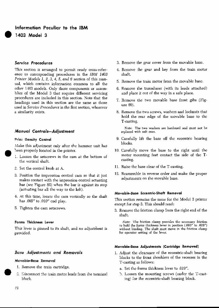
Service Procedures 3. Remove the gear cover from the movable base.
This section is arranged to permit ready cross-refer- ence to corresponding procedures in the ZBM 1403 Printer models 1, 2, 3, 4, 5, and 6 section of this man- ual, which contains information common to all the other 1403 models. Only those components or assem- blies of the Model 3 that require different servicing procedures are included in this section. Note that the headings used in this section are the same as those used in Service Procedures in the first section, wherever a similarity exists.
Print Density Control
\lake this adjustment only after the hammer unit has been properly located in the printer.
1. Loosen the setscrews in the cam at the bottom of the vertical shaft.
2. Set the control knob at A.
3. Position the impression control cam so that it just makes contact with the impression control actuating bar (see Figure 82) when the bar is against its stop (actuating bar all the way to the left).
4. At this time, locate the cam vertically so the shaft has ,005" to .010" end play.
5. Tighten the cam setscrews.
4. Remove the gear and key from the train motor shaft.
5. Remove the train motor from the movable base.
6. Remove the transducer (with its leads attached) and place it out of the way in a safe place.
7. Remove the two movable base front gibs (Fig- ure 69).
8. Remove the two screws, washers and locknuts that hold the rear edge of the movable base to the T-casting.
Note: The two washers are hardened and must not be replaced with soft ones.
9. Carefully lift the base off the eccentric bearing blocks.
10. Carefully move the base to the right until the motor mounting feet contact the side of the T- casting.
11. Raise the base clear of the T-casting.
12. Reassemble in reverse order and make the proper adjustments on the movable base.
Movable-Base Eccentric-Shaft WemovaQ
This section remains the same for the Model 3 printer except for step 3. This should read:
3. Remove the friction clamp from the right end of the shaft.
F O P ~ S Thickness [lever Note: The friction clamp provides the necessary friction to hold the forms thickness lever in position (.003" to ,019")
This lever is pinned to its shaft, and no adjustSent is without binding. The shaft must move in the friction clamp provided. for operator setting of the lever.
Movable-Base Adjustments (Cartridge Removed)
Base Adjustmesats and Wemovads 1. Adjust the clearance of the eccentric-shaft bearing blocks to the front shoulders of the recesses in the
M s v a b i ~ B a s e WemovaU T-casting as follows:
1. Xemove the train cartridge. a. Set the forms thickness lever to .019". 3. Disconnect the train motor leads from h e terminal 5. Loosen the mounting screws (under the T-cast-
block. ing) ior the eccentric-shaft bearing block.

Figure 69. Movable Base (Model 3)
c. Position the block against the front recess in the T-casting with a maximum clearance of .001".
d. Tighten the mounting screws.
2 . Adjust the movable Sase to the T-casting for a maxi- mum clearance cf .aOl" as fol101~-s:
a. Tighten the two front gibs that hold the movable base to the 7-cestiilg 6scren-s under T-casting).
b. Loosen the two locknuts on the two screws that hold the rear edge of the movable base down.
c. Tighten these nuts enough to remove the clear- ance between the screw threads and threads in the T-casting.
d. Hold the nuts with a wrench and adjust each screw to obtain the .00Y maximum clearance be-
73
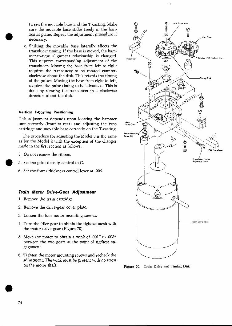
tween the movable base and the T-casting. Make sure the movable base slides freely in the hori- zontal plane. Repeat the adjustment procedure if necessary.
e. Shifting the movable base laterally affects the transducer timing. If the base is moved, the ham- mer-to-type alignment relationship is changed. This requires corresponding adjustment of the transducer. Moving the base from left to right requires the transducer to be rotated counter- clockwise about the disk. This retards the timing of the pulses. Moving the base from right to left, requires the pulse timing to be advanced. This is done by rotating the transducer in a clockwise direction about the disk.
Vertical P-Casting Positioning
This adjustment depends upon locating the hammer unit correctly (front to rear) and adjusting the type cartridge and movable base correctly on the T-casting.
The procedure for adjusting the Model 3 is the same as for the Model 2 with the exception of the changes made in the first section as follows:
3. Do not remove the ribbon. I
Transducer Timing
5. Set the print-density control to C. Adjmfing Screw
6. Set the forms thickness control lever at .004.
Train Mofor Drive-Gear Adjustment
1. Remove the train cartridge.
2. Remove the drive-gear cover plate.
3. Loosen the four motor-mounting screws. I I 4. Turn the idler gear to obtain the tightest mesh with
the motor-drive gear (Figure 70).
5. Move the motor to obtain a wink of .001" to .003" between the two gears at the point of tighZest en- gagement.
6. Tighten the motor mounting screws and recheck the. adjustment. The wink must be present with no stress
r Tmin Drive Motor
-
on the motor shaft. Figure 70. Train Drive and Timing Disk

Pa?tridge Disassembly
If only tlie train type slugs require service, refer to Indizjidzlal Slzrg Removal and Replacement. The fol- lowing steps are given to provide a complete cartridge disassembly procedure.
Sota: If only the upper plate need be removed, remove only the Eve long screws. The four short screws hold the center plate to the baseplate. They are located under the left and right ribbon guides.
1. Note the type arrangement present in the cartridge for reassembly purposes.
2. Remove the ribbon guide bar (Figure 71).
3. Remove the right and left ribbon guides.
4. Remove the pin from each handle-assembly catch, and remove the handles.
5. Place the cartridge upside down on a flat surface with the drive gear to the left.
6. Remove the four short screws and the five long screws that hold the three plates of the cartridge together. Check their location for reassembly pur- poses.
7. Hold the plates together so the type slugs will stay in position. Now turn the cartridge right side up with the drive gear to the left.
8. Carefully remove the upper plate.
9. Remove the drive gear, its shield, and thrust plate. Keep these parts together.
10. Remove the idler gear, its shield, and thrust plate. Keep these parts together.
1%. Remove the center plate. Be very careful to retain all nine spacers. These special spacers are made to a very close thickness tolerance.
12. Remove the type slugs from the track.
13. Clean the type slugs before reassembling the car- tridge.
Train Cleaning
Note: Always remove the train of slugs from the cartridge if the train requires cleaning. Never immerse the complete car- tridge into a cleaning fluid. ii train bind is evidence that the train needs cleaning.
1. Bemove the train from the cartridge (refer to Car- tridge Disassembly).
2. Wash the Qpe slugs in I s l r cleaning fluid (part 450608) or equivalent. using a brush. Place the slugs on a pad of paper towels a d allow them to dry.
3. Use a clean rag or paper towel and wipe the plates clean. (If IBN cleaning fluid is used, be sure it does not contaminate the felt pads.) Use a brush to clean out the angular cleaning slots at each end of the base plate.
Train Cartridge Reassembly
1. Check the felt pads, Figure 71, to be sure that con- tact is maintained from the plugs through the wicks in the bottom of the slug clearance slot. Do not overoil. If new felt plugs are installed, apply about 50 to 60 drops of the special lubricant (part 856381) to them.
2. Make sure that the drive and idler-gear stud oil wicks are in contact with the studs and that they have been supplying oil to the studs. Normally they dc not require re-oiling. They should be just damp. If new oil wicks are installed, apply only enough lubricant (part 856381) to dampen them.
3. Apply only a very thin film of lubricant (part 856381) to the type track on the baseplate. Over- oiling will cause the train to start slowly, and throw oil.
4. Make sure the type slugs are dry. Then place them on the track in proper sequence (Figure 72).
5. Apply a thin film of IBM 17 grease, or equivalent, to the nine washer-like spacers, and place them centered on the screw holes in the baseplate. The grease will help hold the spacers in correct position during reassembly.
6. Assemble the center plate to the base, and check to make sure that all nine spacers are still centered on the screw holes. Move the spacers as required with a spring hook.
7. Assemble the idler gear, shield, and thrust plate.
8. Assemble the drive gear, shield, and thrust plate, with the mark on the drive gear between the - (hy- phen) and R type slugs (Figure 73) on standard arrays or between the U and T type slugs on PCS (preferred character set) trains.
Caution: Be sure that the drive and idler-gear-stud hold- ing screws drop into the holes in the thrust plates (Figure 74) before proceeding. Serious train binds may result if this is not done.
Note: Latest drive gears have a spot mark on top side of the tooth, as well as on the face. On older machines, only the face of the tooth is marked.
Important: Be sure to use the C7 and T slugs that are closest to the =+ symbol.
9. Place the upper plate in position.
10. Lift the cartridge carefully, squeezing the three plates together to maintain the position of the spacers. Pjow turn it upside down.

Handle
Handle Catch Pin (2)
Figure 71. BM 1416 Train Cartridge

Representative Standoid Type Slug Arrangemelts , . - .
'-2
r-2
K S - A
PCS-H
NOTE: Two full retr of one of the obove K S type assemblies are used f a each cartridge arrembly.
Figure 72. Type Location Chart
11. Check to be sure the spacers are still centered on 14. Check the slug-to-slug clearance of the train as the screw holes. If any have moved so they cannot described under Train Slug Clearance Adjustment. be centered, the upper and center plates have 15. Replace the left and right ribbon guides. to be removed and the spacers repositioned. Repeat steps 5, 6, and and again check to make sure 16. Place the cartridge on its side and assemble the
the spacers are positioned properly on the screw handles.
holes. 17. Replace the handle catch pin.
12. Insert all nine plate mounting screws. Be s u e the 18. Replace the ribbon guide bar.
shorter binder-head screws are mounted under the left and right ribbon guide positions. Tightening Procedure for Replacement of Cartridge Gears required for these screws is to start with the screw at the center of the cartridge and to work out to- wards the end. This is to eliminate possible distor- tion of the assembly. If the end of the assembly cartridge is slipped over the edge of the bench, and the screws inserted from below, the possibility of the spacers slipping out of position will be minimized.
13. Check to be sure there is a clearance of .002" to .003" between the setscrews in the upper plate and the gear thrust plates (both ends). Adjust the set- screws as required (Figure 74).
PCS WVU T2 \ y$+ or ($+
The entire cartridge need not be disassembled to re- place the two gears in the cartridge. It is only neces- sary to remove the upper plate and ribbon guides. The following instructions outline the most efficient and easiest method of replacing the gears.
Important
Read ALL Information Provided In Each Step Be-
fore Attempting to Perform the Action Indicated.
1. Before disassembly clean the train by vacuuming, and using the type cleaner paper.
Locknut Upper Plate
1 . Screw to project into Thrust Plate Type Slug hole to prevent rotation o f waher
.002"- .003" clearance between setscrew end and thrust plate with gear against type slugs (2 places)
Figure 73. Type-Slug to Drive-Gear Timing Figure 74. Cpper Plate Screw Adjustments

,.zj , . tf?
Figure 75. Method of Separating Type Slugs
2. Remove the cartridge from the machine and man- ually rotate the train until the R and - (hyphen) slugs line up with the arrow on the lower cartridge plate. The timing mark on the gear tooth should now be visible between these slugs. The tooth is marked by a small slot cut in the top of the tooth. This tooth is in line with the edge of the drive key slot which goes directly through the center of the gear. This can be easily observed on the replace- ment gear.
3. Note the type arrangement of the cartridge in case (because of an accident) it becomes necessary to put the slugs back in the correct order. (See Fig- ure 72.)
4. Remove the ribbon guide bar and the left and right ribbon guides. (Refer to Figure 71.)
5. Remove the roll pins from cartridge handle latches, and remove the handles.
%
6. Place the cartridge upside down with the drive gear to the left on a flat surface and remove the 5 long screws holding the upper cartridge plate. These are the screws farthest from you plus the center screw.
7. The following is a procedure for removing the up- per cartridge plate. Turn cartridge over (topside up). This plate is located by two close tolerance dowel pins and must be kept perfectly parallel to the lower cartridge plate while it is being removed.
As an aid, a jackscrew hole is just to the right of the dowel-pin hole on the drive gear end. Insert one of the screws removed in step 6, and screw it in until it just touches the center plate.
The plates can now be separated by simulta- C
neously lifting the plate at the idler end while turning the jackscrew at the drive gear end. To prevent binding on the dowel pins, the plates must be maintained parallel.
Note: If the gears tend to come up with the upper plate, push them down to keep them in place. This is to prevent loss of the type slug order.
8. Remove the shield and thrust plates from each gear.
Note: The two shields are not identical and must be replaced in their original position.
Slide the idler end of the cartridge over the edge of the table. Push up from below, and lift the idler gear out from above. Keep the type slugs in proper order.
9. Insert the new idler gear. Be sure that no empty tooth appears between any slugs. Be careful not to allow any dirt or ribbon fibers to get between the slugs. There is no timing relation for the idler gear.
10. Repeat the preceding steps with the new drive gear, but be vgry sure the marked tooth is placed between the R and -. A pencil mark on the top of of the gear in line with the timing tooth will aid in keeping the gear in time with the R and - slugs during replacement. Later drive gears have a spot mark on the top side of the tooth as well as on the face. Reinstall the thrust plates and shields on their respective gears.
Note: The flats on the gear shields are cut to provide clearance for the left and right ribbon guides. Replace accordingly.
11. Remove the screw used to jack the upper plate, and reinstall the plate. Start the gear studs into the respective gear bearings and lower the upper plate onto the dowel pins. Do not force it down, work it back and forth if it tends to stick. If it is perfectly parallel to the cartridge assembly it will go on easily.
Note: The thrust plates must be positioned to allow the stud mounting screws to project into the clearance holes in the thrust plate. Rotate the thrust plates with a screwdriver until the screws line up with their respective clearance holes. The upper plate can now be f a y seated.
12. Turn the cartridge over, and replace the 5 screws. Be sure the spacers are in place at each screw hole. They should be, because the center plate has not been removed. This will tend to hold them in place.

13. Before tightening the 5 screws, loosen the other 4 and retighten all 9 screws finger-tight. The upper cartridge plate may bow if there is no clearance be- tween the thrust plates and their adjusting screws (See Figure 74). At this time, check to make sure that there is some clearance at these points before continuing with the tightening sequence. If neces- sary, back off slightly on the adjusting set screws. (The 9 screws passing through the cartridge plates must be very tight, and tightened in sequence to prevent a warped assembly. Starting with tho center screw and working alternately, outwards, tighten all screws to about 3/4 their final torque. Then repeat the sequence tightening them to their final torque.)
14. Check for the clearance of .002" to ,003" between the setscrews and the thrust plates. The setscrews are locked with a jam nut. (See Figure 74.)
15. Replace the handle latches.
16. Before checking or making any adjustment to the slug-to-slug clearance, be sure that there is no dirt lodged between the type slugs. Perhaps the best way to do this is simply to operate the cartridge for a minute or two on the machine.
Caution: Before operating under power, check to see that the train is not bound up tight. If it is, open the slug clearance as described until the train is free, and then run it under power without printing, and with no ribbon.
17. After running under power, check the slug-to-slug clearance. This can best be done with the cartridge in place on the T-casting.
Train-Slug-Clearunce Adjustment
The accumulated slug-to-slug clearance of the type train should be between .001" and .003". To check this clearance, remove the two ribbon guides (Figure 71) and:
1. Open the T-casting and separate any two adjacent slugs at a point to the right of the train idler gear (Figure 75). To do this, hold one of the slugs tight against the track with your left thumb. With your right hand, use a coin to move the adjacent slug to the right.
2. Hold the feeler gage between your left thumb and forefinger so that the gage projects no more than 36" (Figure 76). This is to insure that the gage does not bottom against the track. Make sure the feeler gage is clean. Insert the gage in the separation made
Figure 76. Checking Projection of Feeler Gage

Figure 77. Method of Checking Accumulated Interslug Cap
between the slugs in step 1 (at the butt, or top, not at the character center line).
3. With the feeler gage held between the slugs, move the train to the right across the straight section of the track. Figure 77 shows how to do this by en- gaging the adjacent slug to the right with the coin.
The clearance is correct if the .003" feeler gage produces slight binds, while the .001" feeler gage does not, as the train is moved. If the clearance is correct, rotate the train by hand several times to be certain it has no binds or tight spots. If it is free, proceed to step 5. If it is not, the slug-to-slug clear- ance must be adjusted by performing step 4.
Note: You are checking for freedom of train movement, not for the freedom of the feeler gage in the gap.
4. Correct the accumulated slug-to-slug clearance by adjusting the idler-gear pivot stud as follows: a. Loosen the locking setscrew for the idler gear ad-
justing setscrew (Figure 71). b. Loosen the two screws that hold the idler-gear
stud. c. Partially back out the adjusting setscrew. Move
the idler gear pivot stud against the backed-out adjusting setscrew. Clamp the pivot stud snugly (but not tightly) with the holding screws.
d. Slowly screw in on the adjusting setscrew until -
e the correct accumulated slug-to-slug clearance is obtained.
Note: Take sufficient pains to make this adjustment
carefully, since it can be made only in one direction; that is, by turning in on the adjusting setscrew. If you turn this screw in too far, you have lost the adjustment and must repeat steps a through d.
5. When the correct slug-to-slug clearance has been obtained, tighten the idler-gear pivot-stud holding screws.
6. Recheck the slug-to-slug clearance as described in steps 1,2, and 3. If it is incorrect, repeat all of step 4.
7. Replace the ribbon guides.
Individual Slug Removal and Replacement
1. Remove the cartridge from the printer. 2. Remove the ribbon guide bar (Figure 71). 3. Remove the type slug removal block. 3
4. Rotate the train until the slug to be removed is centered in the removal slot.
5. Remove the type slug. 6. Install the new type slug. Make sure that no paper
dust or dirt from adjacent slugs gets in between them and the new slug.
7. Check for train binds caused by dirt accumulation. 8. Repeat this procedure until all desired slugs have
been replaced. 9. Reassemble in reverse order.
10. Check the type slug clearance after running for one minute. (See Train-Slug-Clearance Adjust- ment.)

Cartridge Interlock Switch Hammer-Unit Assembly
Position the cartridge interlock switch so it is made ~ammer-Unit Assembly Removal @ with .OlP to ,020" overtravel when the cartridge is the forms. seated and locked on the movable base.
2. Remove the top forms guide.
Train Lubricator
The train oil reservoir (Figure 78) is on the lower right side of the T-casting near the hinge. Fill the reservoir with special lubricant (part 856381) only. To prime:
1. Disconnect the supply tube a t the bottom.
2. Lift the plunger slowly and allow it to return by means of its internal spring.
3. Repeat until all air bubbles are expelled from the pump, and oil is available at the outlet.
4. Connect the supply tube.
5. Continue the priming operation until signs of oil appear at the far end of the supply wick. The oil tube need not be filled with oil, but the end of the wick should be moist.
Note: The lubricator motor output shaft rotates at a speed of 1 revolution in 8 hours.
Handle Filler Cap
& Outlet
3. Push the tractors aside to avoid catching the com- pressors on them.
4. Open the rear door and slide the rear forms stacker down out of the way.
5. Remove the inside rear baffle cover.
6. Remove the rear door and cover assembly.
7. Remove the air hose from the hammer unit and place it out of the way.
8. Remove the service mounts from the frame inside the rear left cover and install them.
9. Remove the hammer-unit holding screws.
10. Slide the hammer unit out on the service mounts.
11. Remove the upper and lower hammer unit covers.
Note: This is as far as the hammer unit needs to be re- moved for the majority of service calls. If complete removal is necessary, proceed with the following steps.
Figure 78. Train Lubricator

1'3. Disconnect the hammer unit from the printer. 4. Connect the leads to the proper terminals.
m a. Remove the cable clamps. - - b. Separate the quick-disconnect electrical connec-
tions. c. Remove the cables.
13. Remove the hammer unit from the service mounts.
a. Tilt the hammer unit up (hammers up). b. Remove the clips on the service-mount hand
screws. c. Remove the hand screws. d. Place your forearms with palms up under the
hammer unit. e. Carefully lift the hammer unit with both arms
until it is free of the service mounts. f. Tilt the unit toward you so it cannot fall. g. Withdraw the unit clear of the machine. h. Place the unit on a flat surface.
14. To replace, carefully install the hammer unit in re- verse order.
Warning: Do not let the unit drop. Be sure the magnet leads do not bind or interfere with the magnet armatures when the covers are installed.
a - individual Hammer Magnet Removal
And Replacement
To remove:
1. Perform steps 1 through 11 of Hammer Unit As- sembly Removal.
2. Remove the appropriate magnet-mounting-plate screws, and pivot the plate.
3. Loosen the end screws and pivot the SMS receptacle bracket 90".
4. Remove the magnet-coil slip connectors from their terminals.
5. Remove two screws holding the assembly to the plate (Figure 79). .
6. Remove the magnet assembly.
To replace:
1. Install the magnet assembly with its holding screws snug, but not tight.
2. Center the magnet assembly on the plate with the eccentric tool.
3. Route the magnet leads around the assembly as shown in Figure 79.
5. Close up the hammer unit, and install in the ma- chine.
6. Run the printer and check the printing. Adjust as required. Refer to Individual Hammer Flight-Time Adjustment.
individual Hammer Flight-Time Adjustment
Adjust individual hammers only after determining that the overall timing is correct. Refer to Timing Disk Transducer Adjustments.
1. Remove the top forms guide.
2 . Open the rear door, and slide the rear forms stacker down out of the way.
3. Remove the inside rear baffle cover.
4. Remove the upper or lower hammer unit cover to - -
expose the appropriate hammer magnet assembly mounting screws (Figure 79).
5. Loosen both mounting screws until the magnet as- sembly moves with a firm drag when tbe adjusting tool (part 856170) is rotated.
6. Using either method 1 or method 2 as outl*ed un- der Timing Disk Transducer Adjustments, step 7, operate the printer and adjust the magnet assem- bly until the printed character is centered either on the hammer outline or on the hammer itself. Or, if the two adjacent positions have the correct flight time, center the character between them.
7. Stop the printer and loosen the front magnet- assembly mounting screw until the washer and screw head are free to slide. Then tighten the screw securely.
8. In like manner, loosen and tighten the rear screw.
9. Recheck timing and readjust the magnet assembly, if necessary, starting with step 5.
10. If difficulty is experienced in obtaining this adjust- ment, check the armature-to-backstop air gap (re- fer to Magnet Assembly Backstop Adjustment). Check for binds in the armature, hammer, or push- rod. Replacement of one or more of these parts may be necessary.
11. Reassemble the parts in reverse order.
Individual Hammer-Magnet Coil Replacement
1. Perform steps 1 through 11 of Hammer Unit As- sembly Removal.
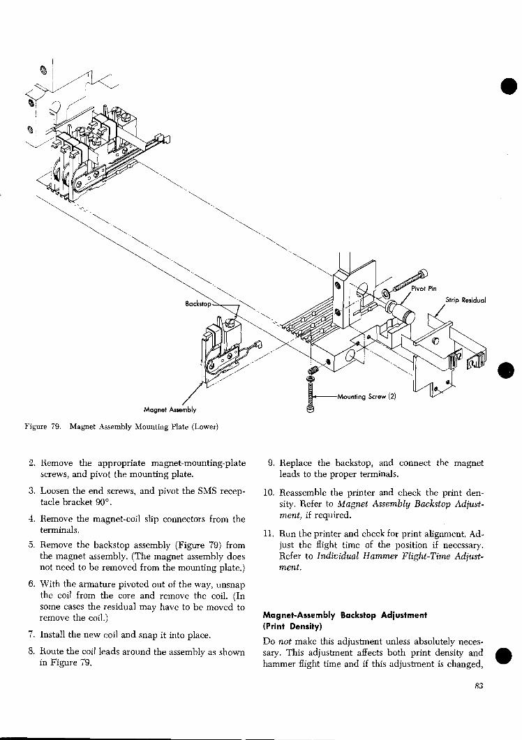
?? / Strip Residual
Magnet Assembly 8 Figure 79. Magnet Assembly Mounting Plate (Lower)
2 . Remove the appropriate magnet-mounting-plate 9. Replace the backstop, and connect the magnet screws, and pivot the mounting plate. leads to the proper terminals.
3. Loosen the end screws, and pivot the SMS recep- 10. Reassemble the printer and check the print den- tacle bracket 90". sity . Refer to iMagnet Assembly Backstop Adjust-
4. Remove the magnet-coil slip connectors from the ment, if required.
terminals. 11. Run the printer and check for print alignment. Ad- 5 . Remove the backstop assembly (Figure 79) from just the flight time of the position if necessary.
the magnet assembly. (The magnet assembly does Refer to Individual Hammer Flight-Time Adjust- not need to be removed from the mounting plate.) ment.
6. With the armature pivoted out of the way, unsnap the coil from the core and remove the coil. (In some cases the residual may have to be moved to remove the coil.) Magnet-Assembly Backstop Adjustment
7 . Install the new coil and snap it into place. (Print Density)
Do not make this adiustment unless absolutelv neces- , - ~ ~ -
8. Route the coil leads around the assembly as shown sary. This adjustment affects both print density and in Figure 79. hammer flight time and if this adjustment is changed,

hammer flight time must be checked. Before proceed- ing with this adjustment, check the following:
- -
1. Binds in the armature pivot, pushrod, and hammer. - - 2. Damaged pushrod.
3. Resistance of the magnet coil. I t should be 8.6 ( 2 0.4) ohms.
4. Thermistor and its connections.
5. Strip residual for wear.
If all other possible causes of poor print density have been eliminated, proceed with the backstop adjustment as follows:
1. Perform steps 1 through 11 of Hammer Unit As- sembly Removal.
3. Remove the appropriate magnet-mounting plate screws (Figure 79), and pivot the plate to gain ac- cess to the magnet assembly.
3. Hold the armature against the core (be sure the strip residual is in position) and check the present clearance between the backstop and the armature. The clearance should be similar to the setting of the properly operating adjacent magnet assemblies.
@ 4. If the clearance compares favorably, go to step 9.
5 . If the clearance is obviously different, continue with step 6 and proceed as far as required.
6. Loosen the backstop clamp screw enough to pro- vide a light drag on the backstop.
7. Rotate the adjusting setscrew (Figure 80) to make the backstop-to-armature clearance similar to adja- cent magnet assemblies. Completely loosen the clamp screw, and retighten.
Armature .023" (nominal - with no residual between armature
I c- i I
Figure 80. Hammer Magnet Assembly
8. Reassemble the machine and check the print den- sity.
9 To increase the print density, increase the back- a stop-to-armature clearance slightly. Loosen the backstop clamp screw enough to provide a light drag on the backstop.
10. Turn in tlie adjusting setscrew about ,002". Now completely loosen the clamp screw and then re- tighten.
11. Reassemble t l ~ e machine and check the print den- sity.
12. Repeat steps 9 through 11 as required.
Forms Compressor Removal and Replacement
To remove:
1. Do steps 1 through 4 of Individual Hammer Re- moval procedure.
2 . Loosen the spring screw and pivot the spring side- ways.
3. Push the compressor pivot pin (Figure 81) out of the hammer mounting block and remove compressor.
To replace:
1. Hold the compressor in position and insert the pivot pin. The end of the pin must be flush with the side of the block.
Spring Retaining Plate I
Pivot Pin X No Molykote G
Figure 81. Hammer Mounting Block Assembly

2. Reposition the end of the spring on the bottom of the compressor and tighten the screw. The end of tlie spring must bear on the straight portion of the compressor adjacent to the radius.
3. Replace the rest as in steps 3 through 5 of Individual Hammer Removal and Replacement.
Individual Hammer Removal and Replacement
To remove a hammer:
1. Perform steps 1 through 11 of Hammer Unit Assem- blg Remo~al.
2. Rotate the unit so the screws on tile bottom of the hammer mounting blocks are accessible.
3. Remove the two screws (Figure 82) from the mount- ing block for the hammer to be removed.
4. Slide the mounting block forward out of its position. If necessary, loosen the adjacent blocks so the block in question may be removed.
At this point, gou have a choice: Perform either step 7, or steps 5 and 6.
5. Remove the hammer spring retaining plate (Figure 81) on the rear of the block. Be careful to retain all springs and plungers.
6. Push the hammer pivot pin out, and remove the hammers to the point where the desired hammer can be removed.
7. Remove the form compressor and its pivot pin. Using this pivot pin as a follower rod, push in the hammer pivot pin until the hammer to be replaced can be removed.
Figure 82. Hammer Slounting Bar hsembly

TI? replace the hummer: On hammers being re- placed, apply a very light film of Molykote* G (part 357830) to the following surfaces only:
-
Contact poi~lt of spring plungers. Both sides of hammer in guide comb area. Contact point of pushrod. Both sides of hammer in pivot area.
The pivot hole, print face and impression control surface must be kept free of Molykote Q3 (see Figure 81). Perform steps 1 and 2, or 3, and steps 4 through 7.
1. Replace the hammer and adjoining hammers one at a time, while moving the pivot pin back to its origi- nal position (flush with the edges of the block).
2. Replace the plungers and springs, then the spring retaining plate. Make sure there is free operation of the hammer, plungers, and springs.
3. Replace the hammer and work the hammer pivot pin into place. Replace the form compressor and its pivot pin.
4. Be sure the sides of the removed hammer block and those loosened are clean.
5. Replace the hammer block and any that were loos-
@ ened or removed originally. All clearance must be = removed between the locating pin on the left end
of the mounting bar and the first hammer block. There must be no clearance between any of the 11 hammer blocks. The blocks must be mounted up against the front of the mounting bar.
6. Both left and right hammer unit locating blocks must be located tightly against their adjacent ham- mer mounting blocks.
7. Repiace the hammer unit in the machine.
Pushrod Removai and WepDecsment
Important: Keep pushrods in their original slots; do pot inter- change them.
1. Move the hammer unit onto the service rails.
2. Remove the upper and lower hammer unit covers.
3. Pivot both top and bottom magnet-assembly mount- ing plates to expose the hammer mounting bar assembly.
4. Remove the complete hammer mounting bar assem-
e bly from the hammer unit.
* Trademark of Alpha-Molykote COT.
Guide Plaf
Tenon(2)-
Lower Plate \
\ Short Pushrod
Long pushrod' \ \ \ \
Shank Back-up Plate
Figure 83. Pushrod Assembly (Inverted)
5. Remove the mounting screws from the top of the appropriate pushrod assembly (Figure 83) and slide the assembly out the rear in a straight line. Use care to avoid losing pushrods out of their slots, and avoid damaging the locating tenons on the bottom of the guides.
6. Remove the three screws at the rear of the assembly with the steel backup plate down. Separate the plates carefully to get at the desired pushrod. Keep pushrodS not being changed in their original slots. Any change may affect print registration.
To rephce the pusJarods:
1. A very light film of Molykote Q3 (part 357830) should be applied to the pushrod, guide, and cover. Do not leave more than a very light film on these parts.
2. Place the pushrod in position and put the guides and backup plate together, making sure all holes line up. Be sure to install the backup plate with its cut comer oriented as shown in Figure 83. This places the close tolerance flat side against the push- rod guide plate.
3. Replace the screws that hold the backup plate to the guides. Be sure the pushrods are in place, then tighten the screws.
4. Place the assembly on the mounting bar with the tenons in the locating slot. The tail of the rear tenon must be against the bar.

3. Check that all pushrods are in position.
Warning: When installed on the mounting bar, the shanks of the pushrod ends must be outside the guides at both ends of the guides.) Now insert the mounting screws and tighten securely.
6. Replace the mounting bar in the hammer unit. Make sure all pushrods operate freely.
7 . Pivot the magnet mounting plates closed, and secure them.
8. Attach the covers, and replace the hammer unit in the machine.
9. Run the printer tests, check print registration, and adjust if necessary. Refer to Individual Hammer Flight-Time Adjustment.
the same as for the Model 2. Refer to the first section of this manual: IBM 1403 Printer Models 1, 2, 3, 4, 5, and 6.
Skew Correction Mechanism
Sense Lever Switch Adjustments
Adjust the switch to operate when the stud on the sense lever (Figure 84) rests on the switch plunger. The plunger must not bottom.
G e a r Switch Adjustment
Position the switch to operate when the gear roller is on the switch plunger. The switch plunger must not bottom.
Ribbon !+$nit Switch 7 and 2 Adjustment (Roll-Pin Type )
Ivith the exception of the skew correction mechanism, 1. Rotate the eccentric shaft (Figure 85) so the rollpin ail ser1;ice procedures for the Model 3 ribbon unit are is actuating the switch.
Figure 84. Sense Lever and Switches

Roll Pin Collar
otor
Eccentric Shaft
Roll Pin Type
Figure 85. Skew Correction Drive
Cam Type
2, Adjust the location of the switch so the plunger just of the pivot plate and upper left ribbon spool as far bottoms when a ,010'' feeler gage is placed between to the froct as possible.
@ the plunger and the rollpin. 4. Tighten the shaft setscrews.
Switch 1 and 2 Adjustment (Cam Type)
1. Rotate the eccentric shaft (Figure 85) so the cam is actuating the switch.
2. Adjust the position of the switch so when the plunger bottoms, there is .015" between the plunger and the high portion of the cam. This is to insure that the cam is not driving the plunger against its stop.
Pivot Plate Eccentric-Shaft Adjustment
This adjustment provides the initial setting for the eccentric and the pivot plate.
1. Important: Position the ribbon reverse lever so the upper ribbon spool is driving.
2. Loosen the eccentric shaft setscrews that hold this shaft to the motor shaft.
@B 3. Rotate the shaft so the eccentric positions the top
Roll-Pin Collar Adjustment
1. Make the eccentric shaft adjustment first, and leave it so the upper left ribbon spool is to the f~ont as far as possible.
2. Loosen the roll-pin collar setscrews (Figure 85) and rotate the collar until switch 2 is just transferred (N/C points, opened). Be sure the collar is aligned properly with both switches.
3. Tighten the setscrews.
Note: This adjustment provides for maximum skew cor- rection. For less correction, adjust the collar to operate Switch 2 either earlier or later.
Switch-Cam Adjustment
1. Make the eccentric shaft adjustment first, and leave it so the upper left ribbon spool is to the f~ont as far as possible.
2. Loosen the setscrews in the cams (Figure 85) and rotate cam 2 until switch 2 is just transferred (N/O

points, opened). Be sure the cam is properly aligned with the switch. Tighten the setscrew.
3. Turn the eccentric shaft 180" (upper left ribbon spool as far as possible to the rear). Rotate cam 1 until switch 1 is just transferred (N/O points, opened). Tighten the setscrews. Make sure the cam is aligned with the switch.
Note: These adjustments provide for maximum skew cor- rection. For less correction, adjust the cam to operate switch 2 either earlier or later.
Print Quality Adiustments
Refer to 1403 CE Memo Service Aid No. 81.
Aligning the Hammer Unit to the Paper Path
i. Open the T-casting.
2. Rotate the eccentric screw, one on each side of the hammer unit, to remove the vertical clearance be- tween the hammer unit and translating frame.
3. Back off on the eccentric screw slightly so the ham- mer unit can slide horizontally front to rear with no binds and the least amount of vertical play.
4. Move the left upper and lower tractors to a point opposite the left hammer unit locating block (see Figure 82).
5. Move the right upper and lower tractors to a point opposite the right hammer unit locating block.
6. Examine the tractor paper guides carefully. If they are bent or deformed and are not flat against the tractor casting, remove and straighten them. It may be helpful to induce a slight bow in the guides (top and bottom arc toward the rear) so when they are remounted, they will be flat.
4. FVith the tractor doors open, place the special Model 3 alignment tool (part 452454) vertically against the tractor paper guide plates (Figure 86). The projection in the center part of the tool is .041".
8. Check for correct clearance between the forms path and the hammer-unit locating blocks at both sets of tractors. Use light pressure to take up the clearance behveen the tractor and the tractor mounting bar without causing any deflection. The contact be- tween the tool and the locating blocks must be light.
9. Adjust the hammer unit bushing stops (see Figure 87), to bring the locating blocks into visible contact with the center portion of the tool.
a. Loosen the two allen-head hammer unit assembly mounting screws.
b. Loosen the two bushing-stop locknuts. Note: Wrench (part 856481) is available for this nut.
c. Turn the bushing stops as much as necessary in the desired direction.
d. Tighten the bushing-stop locknuts and the mounting screws and recheck the adjustment at both sets of tractors.
Figure 86. Hammer Unit to Paper Path Alignment
89
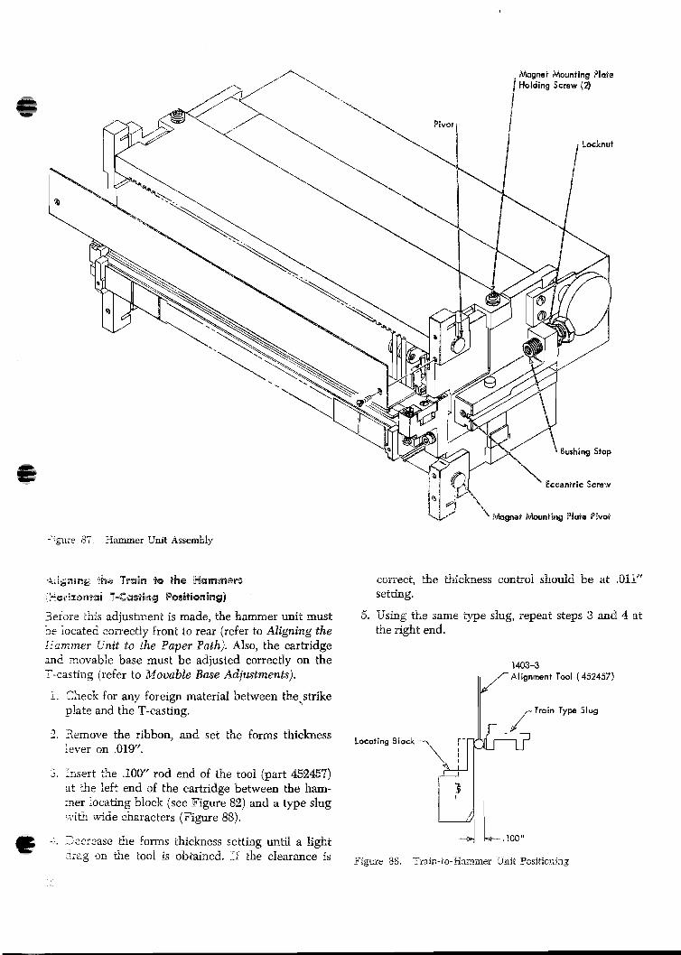
-. -- i e - e 87 aammer Unit Assembly
3er'ore this adjustment is made, the hammer unit must . - 3e 'ocated zorrectly front to rear (refer to Aligning the -?amrner L'nit to the Paper Pntlz). Also, the cartridge a d xovable base must be adjusted correctly on the T-casting (refer to Movable Base Adjustments).
i. Check for any foreign naterid between the..strike plats and the T-casting.
2. 3emove the ribbon, and set the forms thickness lever on .01Y'.
3. Insert Cqe .iOW' rod end of the tool (part 452457) at h e left end of the cartridge between the ham- ner locaL5ng bloc?< (see Figure 82) and a type slug ..:it? wide characters (Figure 88). - :. -eci.ase the iorms thickness setting until a light
- - ~ ; e g r?n ~ \ e tool is abcained. If the clearsnce is
correct, the C9ickness control should be at .OPI" setting.
5. Vsing the same type slug, repeat steps 3 and 4 at the right end.
Locating
452457)
Slug

3. If the clearance is incorrect on the right end of the T-casting, perform step 7. If the clearance is in- correct on the left end of the T-casting, perform step 8.
7 . To adjust the right end of the T-casting, loosen the setscrew on the inside lower end of the T-casting hinge pin. Close the T-casting and loosen the other locking setscrew which is accessible with the T- casting closed. Rotate the T-casting hinge pin until a light drag on the tool is obtained at .011" thick- ness. Lock the hinge pin with the setscrew.
8. ..idjust the left end of the T-casting by loosening the locknut and positioning the adjustable stop stud until a light drag on the tool is obtained at ,011'' thickness.
Tool
Note: Following Steps 7 and 8, the .100" dimension be- tween the hammer blocks and the train should be re- checked at both ends of the cartridge.
9. The T-casting latch may require adjusting for suffi- cient tension of the casting on the stop stud to maintain the T-casting latched. Loosen the two holding screws at the side of the latch, and adjust the allen-head screw from the rear of the printer.
10. Tighten the 76-casting hinge pin locking screw on the inside of the T-casting.
11. Ma-ke a final check with the tool at both ends for proper setting. Readjust if necessary.
Xote: This adjustment may be done in or out of the machine.
i. Set the density control to A, if adjusting in the ma- chine. (The density control automatically returns to the A-setting when the hammer unit is removed.)
2. Check, and adjust, if necessary, the .047" location of the impression control bar. Use tool (part 452457) and measure between the front edge of the impres- sion control bar and the front edge of the hammer unit locating block (see Figure 82). Adjust the po- sition of the impression control wedges to get the .34?" dimension (Figure 89). Check both ends. Lo~sen ,the wedge holding screw and insert a screw- driver into the wedge slot to move the wedge. Tighten the holding screw.
Raise -rAe bz:islating frame as high as possible, if ad- justing .3 th': machine. Adjust the setscrew In the bot- t3n2 3i 1,s c r m compressor ta b r q it: front edge
Figure 89. Impression Control Bar Positioning
.032" from the front edge of the impression control bar in a horizontal direction. Use tool 452457. Lay the cut- out end on the impression control bar, with the ,032'' edge adjacent to the compressor (Figure 90). Make the adjustment while applying finger pressure in a vertical direction to the bottom of the compressor to remove
a clearances in the pivot pin area.
Timing Disk Transducer BlcBg'usfrnents
1. Remove the ribbon and cartridge.
2. Remove the transducer and gear cover.
1403-3 Alignment Tool (452457) Impression \ T C o n t r o l Bor
Compressor 3 ~ d j u s i i n ~ Screw
Fi,pre 3G. Form Compressor Adjustment

Trmsducar Timing Adjtnling Screw .- '
Troin Drive &tor
Figure 91. Train Drive and Timing Disk
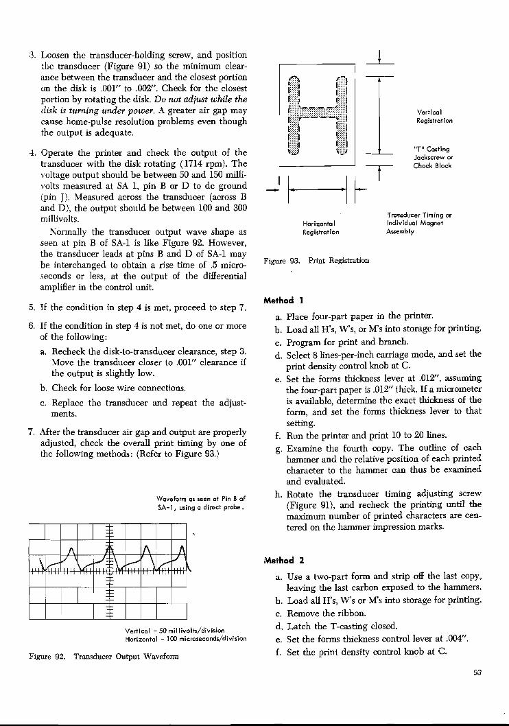
3. Loosen the transducer-holding screw, and position the transducer (Figure 91) so the minimum clear- ance between the transducer and the closest portion on the disk is .001" to .002". Check for the closest portion by rotating the disk. Do not adjust while the disk is turning under power. A greater air gap may cause home-pulse resolution problems even though the output is adequate.
4. Operate the printer and check the output of the transducer with the disk rotating (1714 rpm). The voltage output should be between 50 and 150 milli- volts measured at SA 1, pin B or D to dc ground (pin J). Measured across the transducer (across B and D), the output should be between 100 and 300 millivolts.
Normally the transducer output wave shape as seen at pin B of SA-1 is like Figure 92. However, the transducer leads at pins B and D of SA-1 may be interchanged to obtain a rise time of .5 micro- seconds or less, at the output of the differential ampli6er in the control unit.
5. If the condition in step 4 is met, proceed to step 7.
6. If the condition in step 4 is not met, do one or more of the following:
a. Recheck the disk-to-transducer clearance, step 3. Move the transducer closer to .OOlff clearance if the output is slightly low.
b, Check for loose wire connections.
c. Replace the transducer and repeat the adjust- ments.
7. After the transducer air gap and output are properly adjusted, check the overall print timing by one of the following methods: (Refer to Figure 93.)
Waveform as seen at Pin B of SA-I, using a direct probe.
Vertical - 50 millivolts/division Horizontal - 100 microseconds/division
Figure 92. Transducer Output Waveform
Vertical Registration
"TI' Casting Jackscrew or
Chock Block
Transducer Timing or Horizontal Individual Magnet Registration Assembly
Figure 93. Print Registration
Method 1
a. Place four-part paper in the printer. b. Load all H's, W's, or M's into storage for printing. c. Program for print and branch. d. Select 8 lines-per-inch carriage mode, and set the
print density control knob at C. e. Set the forms thickness lever at .012", assuming
the four-part paper is .012" thick. If a micrometer is available, determine the exact thickness of the form, and set the forms thickness lever to that setting.
f. Run the printer and print 10 to 20 lines. g. Examine the fourth copy. The outline of each
hammer and the relative position of each printed character to the hammer can thus be examined and evaluated.
h. Rotate the transducer timing adjusting screw (Figure 91), and recheck the printing until the maximum number of printed characters are cen- tered on the hammer impression marks.
Method 2
a. Use a two-part form and strip off the last copy, leaving the last carbon exposed to the hammers.
b. Load all H's, W's or M's into storage for printing. c. Remove the ribbon. d. Latch the T-casting closed. e. Set the forms thickness control lever at .004". f. Set the print density control knob at 6.
93

R. Print one line. 3. Mesh the idler gear to the drum and motor gear, - h. Open the T-casting. holding the drum gear in the position of step 1, so
i. R~~~~~ the forms, and observe the imprint of the pointer is about 8" from horizontal toward the
:he characters on the face of the hammers. The front of the machine, as viewed from the top.
relative position of each printed character to the - -
hammer can thus be examined and evaluated. PCS Transducer Output
j. If a majority of the characters are centered on the face of the hammers, the transducer adjust- 1. The air gap between the pointer (see Figure 91) and
meni is proper. If this is not the case, adjust the the transducer should be .0015" to .0045". Move the
transducer with the timing adjusting screw (Fig- transducer to obtain this adjustment. ure 91) and repeat the printing check until it is.
k. use care when wiping the carbon the 2. With the pointer on the train-drive idler gear oper-
hammer faces. Keep lint and other foreign ma- ating continuously, the ~eak-to-peak output of the
terial from getting between the hammers. transducer mnst be 2V minimum. Refer to Figure 55 for a picture of a similar waveform.
5. IYhether method 1 or method 2 is used, adjust indi- vidual hammer positions for centering by use of the 3. With the pointer operating continuously, the ampli-
hammer-magnet assembly eccentric adjusting tool. fied output (at terminal 1 on the amplser) should
Refer to Individual ham me^ Flight-Time Adjust- be a minimum of -8V with a 2- to 30-microsecond
ment. rise time and a 71- to 30-microsecond fall time.
.Vote: If necessary, additional timing adjustment can be obtained by shifting the movable base. Refer to paragraph 2e under Movable Base Adjustments (Cartridge Removed).
4.
On machines equipped with the preferred character set feature, fist perform the Initial Idler to Drum-Gear Mesh.
Note: Reversal of the transducer leads wiU alter the pulse length.
The home PSS (PSS1) pulse must occur completely within the select gate that is formed in the system to which the printer is attached (Figure 94).
If PSSl occurs outside the home select gate, ad- just the pointer on the idler gear. Recheck the air @ gap before starting the machine to prevent damage to the transducer. For a greater adjustment, change the idler gear mesh by one tooth.
lnitiail Idler to Drum-Gem Mesh 7 1. Set the drum gear so the drive key is toward the Gate k l e 2 ms To 2.0 ms
paper (rear of machine) and at 90% to the plane of <
the paper when viewed from the top with the T- casting closed. Pss 3 1 J
I I 2. Set the pointer to the center of its adjustment slot in 4 & 5 u s t o 1 2 0 w s
the idler gear. Figure 94. PSSl Timing

Brint-Queility Concepts
Print quality is an important consideration with any Isxr I403 Printer. However, where the output of a I403 is used for input to an optical-character-recognition system, quality of printing becomes a prime consider- ation.
This is because an IBM I403 Printer that is producing printing that is entirely satisfactory to customers who are visually reading the output may not be producing printing with the characteristics needed for low reject rates in reading machines.
P~inSimg Characteristics Defined Sorile of the terms in this manual are unique to the sub- ject of print characteristics. Definitions of these terms follow.
Average Edge
The typical edge of a printed character is not a strdight h e . The term average edge is defined as an imaginary line that bisects the edge irregularity (Figure 95). Average edges of characters need to be clearly indi- cated because cf the way in which the character recog- ;?ition logic of the optical-character reader is designed.
Stroke Width
X stroke is a portion of a character (Figure 96). It can be a vertical, horizontal, curved, or slanted segment. Stroke width is the distance between the average edges of the stroke.
Density
Density, or ink ccverage, is the blackness of a charac- ter. T h s is determined visually by comparing the character to a comparative density chart.
-. $!@re 95. Average Zdga and Stroke-"Width
Contrast
Contrast is the diflerence in density measurement be- tween the character and the background area. This can also be defined as the diflerence between print reflec- tion from the printed character and background reflec- tion from the surface of the document.
Extraneous ink
Extraneous ink (or other particles) is any spot appear- ing within the reading area not between the average edges of the character. This condition (Figure 97) can be caused by streaks, smears, or splatter. No extrane- ous ink (or particle) whose area is equal to or greater than a half-cell area is acceptable (Figure 98).
Phantom Printing
Phantom printing means printing an unwanted charac- ter that is the next one in sequence on the chain .150" away from the desired character.
Voids
A stroke void in a character (Figure 99) is a light spot that is completely surrounded by ink and is visable to the experienced eye without the aid of a magnifying device. A character void is a light spot that is not com- pletely surrounded by ink and is visable to the eqeri- enced eye.
Slur
A slur is ink that is not a part of the average character outline. Smears, phantom printing, etc., are also in- cluded in this category.
Paint-Qvaiiv Measuring Devices At present, two types of gages are available for meas- uring print qnality.
The thmo strokes that make up the character "One " am drown
3 - by he dotted lines.
3 i y r e 96. Character Stroke
95

3/8" Minimum 1418 Reading Bond
1
L - - - - - - - - - - - - - - - - - - - - - - - - - 1 Centor L i m
Figure 97. Extraneous Ink
Because the extraneous-ink blotch in cell area 1 is less than half the area of the cell, it will not be recognized and, therefore, is
Oocceptable.
The ink blotch in cell area 2 i s greater than half the cell area and is not acceptable.
@ This also applies to the "stringing out" of characters.
NOTE: 407E-1 cell area = 407 - 1 Cell Areas 01875" x .01875".
Figure 98. Extraneous Ink and Cell Areas
Stroke Void
Character Void
Figure 99. Voids
Figure 100. Pocket Comparator
96
Pocket Comparator
An integral part of this device (part 451595) (Figure 100) is an engraved reticle containing the outlines of all the readable characters plus the outline of the permis- sible size of extraneous particles. Figure 101 illustrates the 407-1 reticle (part 451597). A 407 E-1 reticle (part 451596); and a 1428 reticle (part 451995) are also available. With this device you can observe whether the confines of the character are within the minimum and maximum character-stroke widths. Detailed in- structions accompany this device. As optical-character readers are developed to read other fonts or characters, appropriate comparator reticles will be provided. I
Document-Registration Gage
The document-registration gage (Figure 102) can be used to:
1. Locate printing properly on the document. 2. Check the character shape and stroke width. 3. Determine whether any extraneous particles are in
the character-sensing strip (reading band). 4. Check for line skew (printed line must be parallel
to the base line + 2"). 5. Check for proper character pitch and spacing
(maximum character pitch is ten characters per inch).
6. Check the printing for proper vertical and hori- zontal registration.
Figure 101. Pocket Comparator 407-1 T-Reticle

1 2 MIN LENGTH 3 MAX LENGTH 4 5 MIN WIDTH 6 7 8 u u w ~ o m 9 j T T V V
! : # ' I , ! , p l ' : , : , ] , I ! , ! i . ! , l , . . L : ! 1 ; . < ; : . : ; : : ! , 1 , ' / , , . . , / ' ! . . . . . ~J. , : : i ! ! l i . : l i ; l ; l ! :
Figure 102. Document Registration Gage
a 7. Check preprinted vertical field marks for proper size and placement (a character cannot be located closer than .1W' to a preprinted field mark).
8. Check for proper layout and any mark-reading formats.
9. Check the relationship of the timing mark to the marking zone.
10. Define minimum clear areas between mark-read columns.
11. Permit measurement of dimensions and placement .3 of the timing mark.
12. Check pen and pencil marks in the mark-read col- umn for size and placement.
\
Specsc instructions accompany the gage. The docu- ment-registration gage for the IBM 1418 is part 451590; for the IBM 1428, part 451990. By using the pocket
fier, appears ragged and lacks sharpness of edge defi- nition. Figure 103 illustrates character-stroke-width conditions.
Avemge stroke width is at hast .OIOn but leu than .019"
Acceptable
comparator and the document-registration gage, spe- c s c print faults can be identified. Be especially ob-
Minimum strake width servant of stroke width. is l e u than .008" Character-stroke width should measure .OlW' through
.018", except that a maximum of 25% -of the stroke can range from .008" through ,022". This recognizes that ribbon printing, when viewed through a magni- Figure 103. Stroke-Width Conditions

Painter Checks and Adjustments so Meef Optic~l-Reader Requirements The following procedure is suggested whenever the output of a particular IBM 1403 Printer is to be used for optical-reader input. Some of the steps are obvious, and for this reason may be easily overlooked. All the steps are mentioned because they are the factors that have the greatest bearing on print quality.
For aid in diagnosing specific print problems refer to Specific Print Problems and Their Cure.
Correct Font
1. Remove the ribbon and cartridge from the machine.
2. Check the font. It must meet the requirements of the optical-character reader being used. The IBM
1418 Optical Character Reader currently is de- signed for use with either the 407-1 or 407 E-1 style ~selectively, not both). An easily identifiable char- acter is the 4, which has a definite left tm right 45" stroke on the left-hand segment. The IBM 1428 has its own style font.
Type Cleanliness
The type slug must be clean and free of loading in h e lakes of characters such as 8 or 0. Check for pits or breaks in type faces. Clean the types that are dirty or loaded with oil by printing all characters against type cleaner (see On-Cartridge Cleaning). If the type is extremely dirty, perform Of-Cartridge Cleaning.
Chain Tension
1. Hold the cartridge with the printing side up.
2. Move the chain about two passes in,the normal mn- ning direction to be sure that the chain assumes a natural sag from the center plate.
3. The slugs in the center of the cartridge should hang out Kl' (+ .020", - .OOV') to assure proper chain tension (see Figure 26).
4. Adjust the cartridge on current machines by loosen- ing the jam nut and turning the idler adjusting screw.
Cartridge Mountimg
Use care when installing cartridges that are mounted with four cap screws (standard cartridge). Move the cartridge toward the front of the machine while tight- ening the screws. This prevents possible change of the 'hammer-to-cartridge relationship if the cartridge loos- ens for any reason. The interchangeable cartridge is self-aligning.
Excessive Oil and Ink
Wipe off all excess oil, ink, etc. from the cartridge, T-casting, and ribbon shield.
Observe the quantity of oil imparted to the ribbon from the chain-lubrication system. A nominal amount of oil does not greatly affect the print quality. Exces- sive amounts, however, cause a definite problem be- cause of the growth in stroke width and fuzzy edges of the printed characters. If excessive oil is present in the ribbon or around the print area in general, observe the following:
1. Remove the obsolete lubricator for the chain motor when the bevel-gear drive is installed.
2. Use care when .filling the chain reservoir or when oiling the ribbon-drive motor. Oil can drip because of a pressure buildup in the motor.
3. If the chain throws an excessive amount of oil, form the wiper (part 474083) so it just touches the back of the chain. Refer to Chain Lubricator Ad- justment.
Paralleling the Forms Bath, Hammers, and Types
To obtain even print density across the entire line, the forms path, hammers, and types must be parallel. Check and align as directed in Aligning Hammers to Paper Path, Horizontal T-Casting Positioning (Chain to Hammers), and Aligning the Train to the Hammers (Horizontal T-Casting Positioning). @ Ribbon Shield Check the adjustments of the ribbon shield in accord- ance with the section Ribbon Shield and Print-Line Indicator Adjustment.
Timing and Density Adjustment Adjust in accordance with the sections Print-Timing Dial and Adjusting Individual Hammer-Magnet As- semblies for Timing and Density.
Specific Print Problems 'and Their Cure
Density Varlatiom
This can appear in many different ways:
I. 'When irregular sections or spots appear more dense (Figure 104), look for excessive oil in the ribbon. Refer to Excessive Oil and Ink.
2. Sometimes when changing from short-line printing to a longer line, the characters at the beginning and end portions of the line of print are more .
dense than those at the center of the documenr (Figure 105). This can be caused by the unused (more heavily inked) portions of the ribbon.

Figure 104. Density Variation (Irregular)
3. The ribbon shield may be damaged or out of ad- justment. Refer to Ribbon Shield and Print-Line Indicator Adjustment.
4. If density variations exist in groups of 22, check the corresponding impression-control pads.
5. Worn magnet-armature pivots can cause difficulty in timing and density. This requires replacement of the magnet-and-yoke assembly.
6. The hammer-magnet coils can come unglued from the yoke. This can cause light density and late timing.
7. A broken or damaged strip residual can cause den- sity variation. A worn residual on a machine with- out the strip residual requires installation of field B/M 485145 or B/M 485348.
8. When repli~cing an armature on a machine that has strip residuals, beware of old-style armatures with the individual residual. The old-style arma- ture can be used if the individual residual is first removed.
9. Loose platen bond. This can cause light printing at either or both ends. To check:
10. Check for sticky oil and dirt on the hammer re- bound damper bar and the armature tail where they meet. This can cause highly intermittent late timing or light density the first time a hammer is used after a period of no use. The damper bar is easily removed from the rear of the machine for cleaning.
11. Improper chain tension. Refer to Lower Plate-to- Cartridge Reassembly.
12. Check for proper setting of the density lever and the timing dial. Check for proper forms insertion.
13. A fading across the print line indicates that the hammer unit is not parallel to the chain cartridge. Refer to Horizontal T-Casting Positioning (Chain to Hammers).
14. Hammer splay (change in clearance from hammer to hammer). Replace the individual hammer as- semblies to correct a splayed condition. Do this before timing and density adjustments. (See Ad- justing Znditlidual Hammer-Magnet Assemblies for Timing and Density.)
a. Remove the chain cartridge. 15. On difficult-to-analyze erractic-print-density prob- b. Remove the cartridge bottom guide plate. lems, inspect for worn chain-drive gears (excessive c. Press on the platen. If oil oozes from between backlash) or a worn chain-drive sprocket or drive
the platen and its bond, replace the cartridge. key. If certain hammers or groups of hammers ex- (When pinned cartridges are used, replace only hibit timing problems only on certain characters; the cartridge center-bar assembly.) inspect for a damaged or defective timing disk.
Figure 105. Density Variation

Light Tops or Bottoms P8283646566676869606-6-6~~6-6-606
If all characters that are printed have light tops or bottoms, look for tilting of the hammer unit while P5263646566616869606-6-6~~6-606 0 you tighten the locking bolts.
Check the hammer mounting bar. Inspect the sur- 16263646566676869606-6-6etu6-6-606
face that seats against the hammer unit for burrs or Figure 106. Heavy Stroke-Width foreign matter that would prevent proper seating.
Heavy Stroke Width 1 l 1 l 1 1 i 1 1 l 1 1 l 1 1 1 1 ? 1 ~ . 1 ? 1 1 1 ~ 1 Z i 1 1 1 1
Figure 106 shows an example of heavy stroke width t 1 11 1 1 1 1 1 1 L 1 1 1 L 1 1 1 1 1 1 ' i 1 1 1 I ! ' and extraneous particles. This condition is most preva- t 1 2 t 3 1 / , 1 3 1 / ) 1 7!?l ~ ~ ? - ~ : 7 r - ~ - ~ " ~ - - ' 3
L . ' L - lent in early ribbon life. You can compensate by using a lighter impression during early stages of ribbon life. 1 1 2 t 3 1 'I 1 5 1 6 ! ' ? 2 l [ ; l n l - l 1 J ; - i 1 3 ; q ; ~
This causes lighter printing on carbon copies of mul- lo7. Light Shoke-Width tiple documents. (The original is used for optical- character sensing.)
Light Stroke Width (All Characters) -05555555555555555555555555555555 Figure107showsanexampleoflightornarrowstroke -Op5253545556575859505-5~~5-58595 width. This occurs at the end of ribbon life.
-0P5253545556575859505-5aU5-58595
Light Stroke Width (Individual Hammers)
Figure 108 is an example of light or narrow stroke width at the left edge of individual characters, column h f each line. Correcting this condition requires indi- vidual hammer timing adjustment. Refer to Adjusting Individual Hammer-Magnet Assemblies for Timing and Density.
Phantom Printing
- 0 1 5 2 5 3 5 4 5 5 5 6 5 7 5 8 5 9 5 0 5 - 5 ~ ~ 5 - 5 0 5 9 5
Figure 108. Light Stroke-Width (Individual)
Slur
Refer to the area marked B in the enlargement (Figure 109). This is caused by hammer-chain speed relation- ship and the weight of the document used. This con- dition is accentuated when card stock or other heavy stock is used. Adjust the paper guides for minimum
Refer to the area marked A in the enlargement (Fig- ure 109). This occurs because of the stifmess of the document. It is encountered when printing on card stock or other heavy forms. Adjust the paper guides Wavy Printing (Horizontal Misalignment)
and use a lighter-inked ribbon to minimize phantom To correct faulty spacing, skipping, or horizontal align- printing. ment, refer to Carriage Adjustments.

I . .
Figure 109. Phantom Printing and Slur

kocafiosos and Voltage Specifications
Voltage Mainline Switch (AC Power)
The carriage motor, the type-chain drive motor, and This is at th'e left rear comer of the cover frame. Cau- the hammer blower motor are 208-230 volts ac 3-phase tion: Use this switch to condition the printer. Operate motors. Warning: Be careful of this voltage. it only when the system power is off. It does not re-
move all dc voltages.
Voltage Variation Convenience Outlet When connected to the system, the printer must con- This is available from underneath at the rear of the t ime to perform all speciFed functions within the fol- lowing voltage ranges:
Line Voltage + 10%. Terminal Blocks -mi- dc *4% at component using TB-I, 10-position terminal; rear cover frame. - 6V dc *4% at component using TB-2, &position terminal; in hydraulic resenroir. - 6V dc *4% at using TB-3, 3-position terminal; on printer casting at upper -12V dc 2 4 % at component using voltage left.
C E V dc 2 4 % at component using voltage TB-4, for hammer magnet; (when installed, blower).
-20V dc +4% at component using voltage TB-5, 2-position terminal; on ribbon-drive unit.
TB-6, 4-position terminal; on ribbon-drive unit.
TB-7, 6-position terminal; on T-casting at left rear. Serial Plate
TB-8, 2-position terminal; on T-casting at left rear. This is mounted on the top surface of the right cover frame. TB-9, on manifold assembly, right side of machine (50
cycles only).
TB-10, 5 positions, on translator frame, behind upper
Ground tractors.
The ground connections are made at the left front TB-11, 5 positions, on translator frame, behind lower
comer of the cover frame. tractors.
Thermistors Connectors All 1403 printers have thermistors. Electrically they are
The two signal connectors and one power connector in series with the print hammer magnets and are in the enter the printer at the left. response (return) side of the line. Physical locations of
the thermistors vary with the models. In numeric machines, they are at the front left of the
Resistors printer.
In the Model 3, they are mounted on the hammer These are at the rear of the printer at the upper right unit paddle card connectors. above the hydraulic unit. The carriage resistors are on On Models 1, 2, 4, 5, and 6, they are near the left a heat sink behind the hydraulic unit. side frame at the rear of the machine.
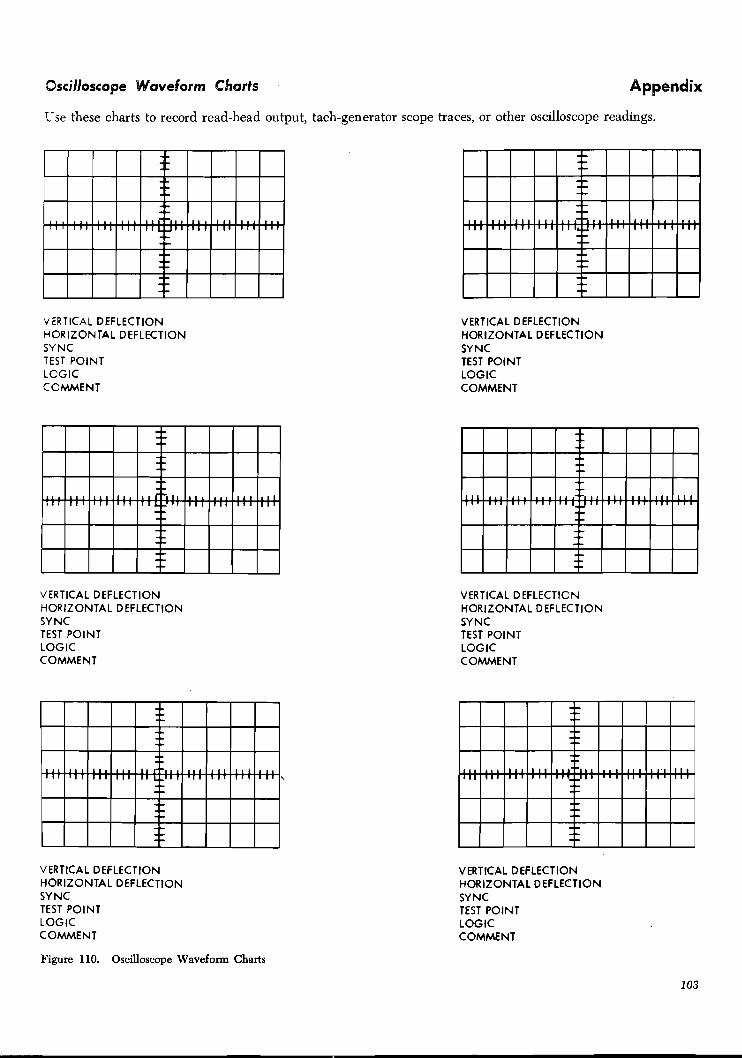
Ssci~loscoge Waveform Charts Appendix
L-se these charts to record read-head output, tach-generator scope traces, or other oscilloscope readings.
VERTICAL DEFLECTION HORIZONTAL DEFLECTION SYNC TEST POlNT LOGlC COMMENT
VERTICAL DEFLECTION HORIZONTAL DEFLECTION SYNC TEST POlNT LOGlC COMMENT
VERTICAL DEFLECTION HORIZONTAL DEFLECTION SYNC TEST POlNT LOGlC COMMENT
VERTICAL DEFLECTION HORIZONTAL DEFLECTION SYNC TEST POlNT LOGIC COMMENT
VERTICAL DEFLECTION HORIZONTAL DEFLECTION SYNC TEST POlNT LOGlC COMMENT
VERTICAL DEFLECTION HORIZONTAL DEFLECTION SYNC TEST POINT LOGlC COMMENT
Figure 110. Oscilloscope Waveform Charts

Print Troubleshooting Reference Chart
This table shows scan on which a particular character will print in position 1 with Print Start tied to Home Pulse.
+ Figure 111. Characters Printable during Subscans 1, 2, and 3 of Print Scan 1
104

Index
Acoustical Dampener Device ............................................... 29 hdjusting Individual Hammer-Magnet .b semblies for Timing and Density ................................ 41
Aligning the Hammer to the Paper Path ........................ 38. 89 Aligning the Train to the Hammer ...................................... 90 Appendix ................................................................................ 103 Auxiliary Ribibbon - Correction Device ................................ 47 Average Edge ..................................................................... 95
Base Adjustments and Removals .......................................... 72 Bevel Gear Unit Lubrication ............................................. 36 B>pass Seedle-Valve Adjustment (Pencil Trace) ................ 60 B>pass Seedle-Valve Adjustment (Tach-Generator) ............ 64
Caniage Adjustment with the Tachometer-Generator ...... 63 Carriage Adjustments ............................................................ 57 Cartridge Disassembly .......................................................... 75 Cartridge Gear Replacement ............................................... 77 Cartridge Interlock Switch .................................................... 81 Cartridge Mounting ........................................................... 98 Center and Upper Plate Reassembly ................................... 33 Chain Cartridge Disassembly (Out of Machine) .............. 31 Chain Cartridge Removal ...................................................... 30 Chain Cleaning ...................................................................... 31 Chain-Lubricator Adjustment ................................................ 37 Chain Tension ....................................................................... 98 Chain-to-Cartridge Reassembly ............................................ 33 Connectors .............................................................................. 102
.................................................................................. Contrast 95 Control-Valve-Body Assembly Removal
(Reservoir not Removed) ................................................. 53 Control-Valve-Body Assembly Removal
.......................................................... (Reservoir Removed) 52 Convenience Outlet ............................................................. 102 Correct Font ............................................................................ 98
........................................................................ Cover Removal 10
Density .................................................................................... .................................................................... Density Variation
Disassembly of the Ribbon-Drive and Drag Assembly ............................................................
Document-Registration Gage ................................................ Double-space Single-Shot Adjustments ................................ Dynamic Adjustment of the Carriage-Tape
................................................................................ Brushes
Emitter-Brush Timing (Pencil Trace) .................................... Emitter Brush Timing (Tach-Generator) .............................. Excessive Oil and Ink ............................................................ Extraneous Ink ........................................................................
Forms Carts Grounding ...................................................... 21 Forms Compressor Adjustment .............................................. 91 Forms Compressor Removal and Replacement .................... 84 Fom-Stacker Assembly Adjustment .................................... 20 Forms Thickness Lever ........................................................ 72 Forms-Tractor Adjustment .................................................... 16 Forms-Width Vernier .............................................................. 12
Ground ................................................................................ 102
.................................... Hammer-Magnet-Assembly Removal 39 Hammer Unit Assembly ........................................................ 81
.................................................... Hammer-Unit Removal 37. 81 ............................................................ Heavy Stroke Width 100
.................................. Horizontal T-Casting Positioning 26. 90 ...................................... Hydraulic Detent Stop Adjustment 59 .................................... Hydraulic-Pump Drive-Belt Tension 55 ................................. Hydraulic-Unit Oil-Seal Replacement 56
.................................................. Hydraulic-Unit Reassembly 54 ........................................................ Hydraulic-Unit Removal 51
......... ...................................... Hydraulic-Unit Replacement i 52 ........................................ Hydraulic-Unit Reservoir Removal 52
........................... ................... IBM 1416 Train Cartridge : 75 ...................................... Impression Contml Bar Adjustment 91
Individual Hammer Flight-Time Adjustment ...................... 82 ............ Individual Hammer-Magnet-Assembly Adjustment 40
............ Individual Hammer-Magnet-Coil Replacement 39. 82 Individual Hammer Magnet Removal and Replacement 82
............................................... Individual Hammer Removal 40 ................ Individual Hammer Removal and Replacement 85
.............................................. Individual Pin-Feed Removal 16 ................ Individual Slug Removal and Replacement 35. 80
Installation Procedure ....................................................... 5
.................................................. Left Shock-Mount Leveling 21 ................................ Light Stroke Width (All Characters) 100
...................... Light Stmke Width (Individual Hammers) 100 ........................................................ Light Tops or Bottoms 100
................................................................................ Locations 102 Lower Plate-to-Cartridge Reassembly .................................... 33
................................ Magnet-Assembly Backstop Adjustment 83 Magnetic Emitter Adjustment .............................................. 61
.......... Magnetic Emitter Timing (Models 3. 4. 5 and 6) 68 ............................ Magnetic Emitter Timing (Pencil Trace) 62
...................... Magnetic Emitter Timing (Tach-Generator) 68 ........................................ Magnetic Read-Head Adjustment 36
................................................................ Main Line Switch 102 ............................ Manual-Clutch and Lineselection Knob 14
.................................... Manual Controls - Adjustment 11. 72 .................................... Model 3 - Information Peculiar To 72
.................................................................. Model 6 Carriage 51 ............................................................ Motor Rotation Check 8
.............................................. Movable-Base Adjustment 23. 72 ........................ Movable-Base Eccentric-Shaft Removal 23. 72
.................................................... Movable-Base Removal 22. 72
New Style Ribbon-Shield Replacement Procedure .............. 44
Oscilloscope Waveform Charts ............................................ 103
Paralleling the Forms Path. Hammers. and Types .............. 98 PCS Transducer Adjustment ................................................ 94 PCS Transducer Output ........................................................ 94
.......................................................... Phantom Printing 95, 100 .................................................................. Pocket Comparator 96
Preventive Maintenance .......................................................... 5 .......................................................................... Print Density 83
Print Density Control ............................................................ 72

Print Problems and Their Cure .......................................... 98 Print Quality Adjustments .................................................... 89 Print-Quality Concepts ....................................................... 95 Print Quality Measuring Devices ........................................ 95 Print Timing Dial ................................................................. 12 Print Troubleshooting Reference Chart ............................ 104 Printer Checks and Adjustments for
Optical Reader Requirements ............................................ 98 Printing Characteristics Defined ............................................ 95 Process Meter Test .................................................................. 9 Pushrod Removal and Replacement ...................................... 86
Resistors ........................................................................... 102 ...... Removable Ribbon Guide-Wire Device Adjustments 44
Removable Ribbon Guide-Wire Installation ........................ 44 Ribbon-Clutch Removal and Adjustment ............................ 46 Ribbon-Drive and Drag-Assembly Removal ........................ 45 Ribbon Drive-Motor Positioning ........................................... 47 Ribbon Drive-Unit Positioning .............................................. 41 Ribbon-Drive-Unit Removal .................................................. 41 Ribbon Shield ........................................................................ 98
...... Ribbon Shield and Print-Line Indicator Adjustment 41 Ribbon-Skew Adjustment ...................................................... 41 Ribbon Unit ...................................................................... 41. 87
Safety ........................................................................................ 5 Serial Plate ............................................................................ 102 Senice Procedures ............................................................... 72 Single-Shots .............................................................................. 85
.......... Single-space Single-Shot Adjustment (Pencil Trace) 61 .... Single-space Single-Shot Adjustment (Tach-Generator) 66
Skew Correction Mechanism ................................................ 87 Skip Control-Magnet Adjustment ........................................ 59 Skip Control-Valve Adjustment ............................................ 59 Skip Needle-Valve Adjustment ............................................ 60 Slur .................................................................................. 95, 100 Space Control-Magnet Adjustment ...................................... 57 Space Control-Valve Adjustment .......................................... 58 Space Needle-Valve Adjustment .......................................... 59 Static Adjustment of the Carriage-Tape Brushes ................ 70 Stroke Width ......................................................................... 95
.......................................................... Swing-Pan Adjustment 30 System Check-Out .................................................................. 9
................................................ T-Casting Latch Adjustment ................................................................ T-Casting Removal
.......................................................... T-Casting Replacement .............................. Tach-Generator and Scope Connections
.................................... Tape-Controlled Hydraulic Carriage Terminal Blocks .................................................................... Thermistors ............................................................................
.................................................. Timing-Disk Magnetization ................................ Timing Disk Transducer Adjustments
........................................ Timing and Density Adjustment Top Forms Guide ....................................................................
................................................................ Tractor Installation ...... Tractor Jam-Detection Device Adjustment (Old Style)
.......... Tractor-Mounted Jam-Detection Device Adjustment .................... Tractor-Shaft and Mounting-Bar Replacement
.......... Tractor Shafts and Tractor Mounting Bars Removal Train Cartridge Reassembly ....................................................
........................................................................ Train Cleaning Train Lubricator ......................................................................
.................................. Train Motor Drive-Gear Adjustment .......................................... Train-Slug-Clearance Adjustment
................................................ Translator-Frame Positioning .................................................... Translator-Frame Removal
Translator Lock-Lever ............................................................ ........................................................ Translator Vernier Knob
Triple-space Single-Shot Adjustment .................................... .................................................................... Type Cleanliness
Upper and Lower Tractor Drive-Shaft Positions ................ 18
............................................ Vertical Print-Alignment Knob 11 ...................................... Vertical T-Casting Positioning 27. 74
Voids ........................................................................................ 95 .................................................................................. Voltage 102
.......................................................... Voltage Specifications 102 Voltage Variation ................................................................. 102
Wavy Printing (Horizontal Misalignment) .......................... 100

l l u O e n ~ f a M
Field Engineering Maintenance Manual : I BM 1403 Printers; Form 225-6493-4
@ PS the material: Yes SatiPfactory
Easy to read? Well organized? Fully covered? Clearly explained? Well illustrated?
How did you use this publication? As an introduction to the subject For additional knowledge of the subject
Which of the following terms best describes your job? Customer Personnel ZBAl Persotanel
Manager Customer Engineer Systems Analyst Instructor Operator Sales Representative [7 Programmer Systems Engineer Trainee Trainee [7 Other Other
Check specific comment (if any) and explain in the space below: (Give page number)
Suggested Change (Page ) Suggested Addition (Page ) [7 Error (Page ) Suggested Deletion (Page )
Explanation :
Space is available on the other side of this page for additional comments. Thank you for your cooperation.

Fold I I Fold I
FIRST CLASS
PERMIT NO. 170
ENDICOTT, N . Y.
B U S I N E S S R E P L Y M A I L N O POSTAGE NECESSARY IF MAILED I N THE UNITED STATES
POSTAGE WILL BE PAID BY . .
IBM Corporation
P. 0. Box 6
Endicott, N. Y. 13764
Attention: Product Publications, Dept. 171
Fold Fold I - I I I I I I I I I I I I I I I
International Business Machines Corporation I I
Field Engineering Division
112 East Post Road, White Plains, N. Y. 10601


