SNAP I/O WIRING GUIDE Form 1403-060619—June 2006 43044 Business Park Drive • Temecula • CA 92590-3614 Phone: 800-321-OPTO (6786) or 951-695-3000 Fax: 800-832-OPTO (6786) or 951-695-2712 www.opto22.com Product Support Services 800-TEK-OPTO (835-6786) or 951-695-3080 Fax: 951-695-3017 Email: [email protected]Web: support.opto22.com
Transcript
SNAP I/O WIRING GUIDE
Form 1403-060619—June 2006
43044 Business Park Drive • Temecula • CA 92590-3614Phone: 800-321-OPTO (6786) or 951-695-3000
Fax: 800-832-OPTO (6786) or 951-695-2712www.opto22.com
Product Support Services800-TEK-OPTO (835-6786) or 951-695-3080
The information in this manual has been checked carefully and is believed to be accurate; however, Opto 22 assumes no responsibility for possible inaccuracies or omissions. Specifications are subject to change without notice.
Opto 22 warrants all of its products to be free from defects in material or workmanship for 30 months from the manufacturing date code. This warranty is limited to the original cost of the unit only and does not cover installation, labor, or any other contingent costs. Opto 22 I/O modules and solid-state relays with date codes of 1/96 or later are guaranteed for life. This lifetime warranty excludes reed relay, SNAP serial communication modules, SNAP PID modules, and modules that contain mechanical contacts or switches. Opto 22 does not warrant any product, components, or parts not manufactured by Opto 22; for these items, the warranty from the original manufacturer applies. These products include, but are not limited to, OptoTerminal-G70, OptoTerminal-G75, and Sony Ericsson GT-48; see the product data sheet for specific warranty information. Refer to Opto 22 form number 1042 for complete warranty information.
Cyrano, Opto 22 FactoryFloor, Optomux, and Pamux are registered trademarks of Opto 22. Generation 4, ioControl, ioDisplay, ioManager, ioProject, ioUtilities, mistic, Nvio, Nvio.net Web Portal, OptoConnect, OptoControl, OptoDisplay, OptoENETSniff, OptoOPCServer, OptoScript, OptoServer, OptoTerminal, OptoUtilities, SNAP Ethernet I/O, SNAP I/O, SNAP OEM I/O, SNAP PAC, SNAP Simple I/O, SNAP Ultimate I/O, and SNAP Wireless LAN I/O are trademarks of Opto 22.
ActiveX, JScript, Microsoft, MS-DOS, VBScript, Visual Basic, Visual C++, and Windows are either registered trademarks or trademarks of Microsoft Corporation in the United States and other countries. Linux is a registered trademark of Linus Torvalds. Unicenter is a registered trademark of Computer Associates International, Inc. ARCNET is a registered trademark of Datapoint Corporation. Modbus is a registered trademark of Schneider Electric. Wiegand is a registered trademark of Sensor Engineering Corporation. Nokia, Nokia M2M Platform, Nokia M2M Gateway Software, and Nokia 31 GSM Connectivity Terminal are trademarks or registered trademarks of Nokia Corporation. Sony is a trademark of Sony Corporation. Ericsson is a trademark of Telefonaktiebolaget LM Ericsson.
All other brand or product names are trademarks or registered trademarks of their respective companies or organizations.
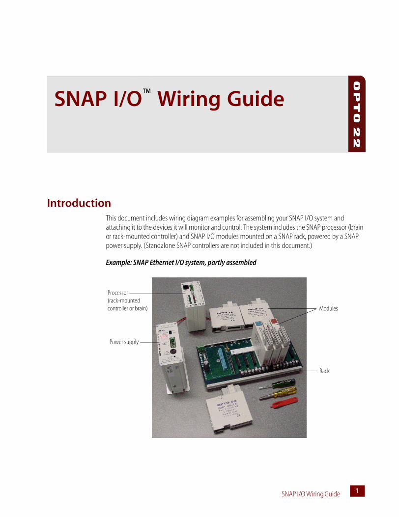
IntroductionThis document includes wiring diagram examples for assembling your SNAP I/O system and attaching it to the devices it will monitor and control. The system includes the SNAP processor (brain or rack-mounted controller) and SNAP I/O modules mounted on a SNAP rack, powered by a SNAP power supply. (Standalone SNAP controllers are not included in this document.)
This document includes basic wiring information for SNAP racks, power supplies, processors (brains or rack-mounted controllers), and I/O modules. For more information, see the data sheet and the installation or user’s guide for your specific products.
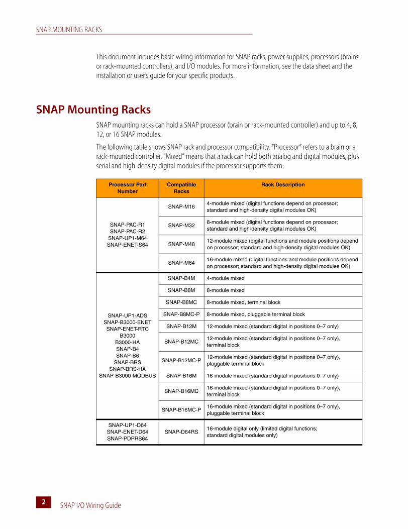
SNAP Mounting RacksSNAP mounting racks can hold a SNAP processor (brain or rack-mounted controller) and up to 4, 8, 12, or 16 SNAP modules.
The following table shows SNAP rack and processor compatibility. “Processor” refers to a brain or a rack-mounted controller. “Mixed” means that a rack can hold both analog and digital modules, plus serial and high-density digital modules if the processor supports them.
Processor Part Number
Compatible Racks
Rack Description
SNAP-PAC-R1SNAP-PAC-R2
SNAP-UP1-M64SNAP-ENET-S64
SNAP-M164-module mixed (digital functions depend on processor;standard and high-density digital modules OK)
SNAP-M328-module mixed (digital functions depend on processor; standard and high-density digital modules OK)
SNAP-M4812-module mixed (digital functions and module positions depend on processor; standard and high-density digital modules OK)
SNAP-M6416-module mixed (digital functions and module positions depend on processor; standard and high-density digital modules OK)
SNAP-B12M 12-module mixed (standard digital in positions 0–7 only)
SNAP-B12MC12-module mixed (standard digital in positions 0–7 only), terminal block
SNAP-B12MC-P12-module mixed (standard digital in positions 0–7 only), pluggable terminal block
SNAP-B16M 16-module mixed (standard digital in positions 0–7 only)
SNAP-B16MC16-module mixed (standard digital in positions 0–7 only), terminal block
SNAP-B16MC-P16-module mixed (standard digital in positions 0–7 only), pluggable terminal block
SNAP-UP1-D64SNAP-ENET-D64SNAP-PDPRS64
SNAP-D64RS16-module digital only (limited digital functions; standard digital modules only)
SNAP MOUNTING RACKS
SNAP I/O Wiring Guide 33
Racks Without Terminal Strips
SNAP racks come either with or without a common terminal strip. The following diagram shows a rack without a terminal strip. For this type of rack, all wiring connections are made to the field connectors on the top of each module. A processor is shown on this rack, but the modules have not been inserted yet.
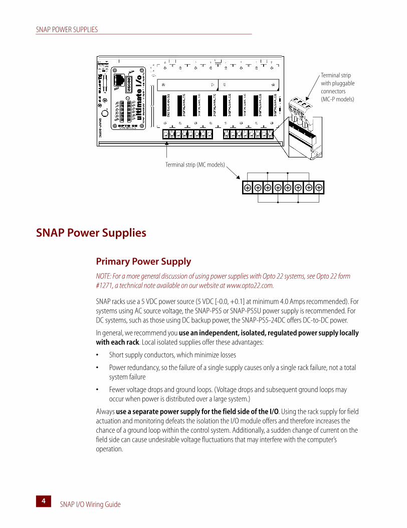
Racks with Terminal Strips
If your rack has a terminal strip, you can use it for field wiring common connections, such as loop power distribution, or low-current applications. The following diagram shows a rack with a terminal strip (MC rack models); the smaller diagram shows the optional terminal strip with pluggable connectors (MC-P rack models). Terminal strips do not connect to SNAP modules; depending on your application, you may need to install wiring from the terminal strip to the module. (Again, the rack is shown with a processor but with no modules.)
SNAP POWER SUPPLIES
SNAP I/O Wiring Guide4
SNAP Power Supplies
Primary Power Supply
NOTE: For a more general discussion of using power supplies with Opto 22 systems, see Opto 22 form #1271, a technical note available on our website at www.opto22.com.
SNAP racks use a 5 VDC power source (5 VDC [-0.0, +0.1] at minimum 4.0 Amps recommended). For systems using AC source voltage, the SNAP-PS5 or SNAP-PS5U power supply is recommended. For DC systems, such as those using DC backup power, the SNAP-PS5-24DC offers DC-to-DC power.
In general, we recommend you use an independent, isolated, regulated power supply locally with each rack. Local isolated supplies offer these advantages:
• Short supply conductors, which minimize losses
• Power redundancy, so the failure of a single supply causes only a single rack failure, not a total system failure
• Fewer voltage drops and ground loops. (Voltage drops and subsequent ground loops may occur when power is distributed over a large system.)
Always use a separate power supply for the field side of the I/O. Using the rack supply for field actuation and monitoring defeats the isolation the I/O module offers and therefore increases the chance of a ground loop within the control system. Additionally, a sudden change of current on the field side can cause undesirable voltage fluctuations that may interfere with the computer’s operation.
Terminal strip (MC models)
Terminal strip with pluggable connectors (MC-P models)
SNAP POWER SUPPLIES
SNAP I/O Wiring Guide 55
Determining Power Requirements
Both the SNAP-PS5 and the SNAP-PS5-24DC power supplies provide 5 VDC power for loads up to 4 Amps. The SNAP-PS5U provides 5 VDC for loads up to 5 Amps. In most cases this power is sufficient for a SNAP processor, a rack, and the associated I/O modules. However, some combinations of modules, especially special-purpose modules, may require additional power. You can use the following tables to help determine power needs for your I/O units.
Processor Power Requirements
I/O Unit (Processor, Rack, and I/O Modules) Power Requirements Worksheet
Processor (Brain or Rack-mounted Controller) Power Req. (Amps)*
SNAP processor (Enter Amps from Processor Power Requirements table)
1
SNAP-IDC5-SW digital input moduleSNAP-IDC5-SW-NC digital input module
0.200
All other standard digital input and output modules (not high-density digital modules)
0.050
High-density digital input and output modules** 0.150
SNAP-AICTD analog input moduleSNAP-AICTD-4** analog input moduleAll analog output modules
0.150
SNAP-AIARMS analog input moduleSNAP-AIVRMS analog input moduleSNAP-AIMA and AIMA-4** analog input modulesSNAP-AITM and AITM-2 analog input modulesSNAP-AIMV-4** and AIMV2-4** analog input modulesSNAP-AIV and AIV-4** analog input modules
0.170
SNAP POWER SUPPLIES
SNAP I/O Wiring Guide6
IMPORTANT: For a SNAP-PS5 or a SNAP-PS5-24DC power supply, the total power required must not exceed 4 Amps. For a SNAP-PS5U, the total power required must not exceed 5 Amps.
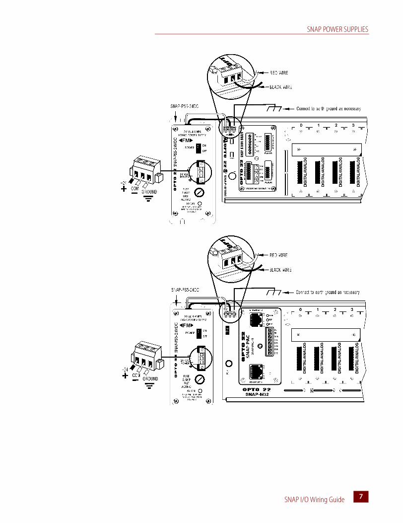
Wiring the Primary Power Supply
Use one power supply per I/O unit. Use 14 AWG wire.
1. Mount the SNAP-PS5 or SNAP-PS5-24DC power supply so that the attached red and black power wires will reach the + and – power terminals on the SNAP mounting rack.
2. Using the power terminals on the SNAP mounting rack, attach the red wire to the + terminal and the black wire to the – terminal. Connect the ground terminal on the SNAP rack to ground.
3. For the SNAP-PS5 (not illustrated): Using the removable input power connector on top of the power supply, apply 120 volts AC power between the two terminals marked “AC.” Connect the ground terminal to ground.
4. For the SNAP-PS5U (not illustrated): Using the removable input power connector on top of the power supply, apply 240 or 120 volts AC power between the two terminals marked “AC.” Connect the ground terminal to ground.
5. For the SNAP-PS5-24DC (illustrated below): Using the removable input power connector on top of the power supply, apply 24 volts DC power between the two terminals marked “±DC.” Connect the ground terminal to ground.
SNAP-AIRTD analog input moduleSNAP-AIR40K-4** analog input moduleSNAP-AIRATE analog input module
0.190
SNAP-AIPM power monitoring module** 0.100
SNAP-AILC load cell module** 0.120
Isolated analog input modules(part numbers ending in -i or iSRC)
0.200
Serial or Profibus modules** 0.250
Total* Current from 5-volt supply** Can be used with SNAP PAC R-series, SNAP Simple, SNAP Ethernet, and SNAP Ultimate
Item QuantityX Power Req. (Amps)
Total Power Required (Amps)**
SNAP POWER SUPPLIES
SNAP I/O Wiring Guide 77
SNAP POWER SUPPLIES
SNAP I/O Wiring Guide8
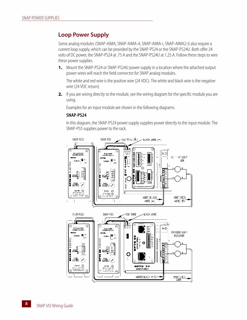
Loop Power Supply
Some analog modules (SNAP-AIMA, SNAP-AIMA-4, SNAP-AIMA-i, SNAP-AIMA2-i) also require a current loop supply, which can be provided by the SNAP-PS24 or the SNAP-PS24U. Both offer 24 volts of DC power, the SNAP-PS24 at .75 A and the SNAP-PS24U at 1.25 A. Follow these steps to wire these power supplies.
1. Mount the SNAP-PS24 or SNAP-PS24U power supply in a location where the attached output power wires will reach the field connector for SNAP analog modules.
The white and red wire is the positive wire (24 VDC). The white and black wire is the negative wire (24 VDC return).
2. If you are wiring directly to the module, see the wiring diagram for the specific module you are using.
Examples for an input module are shown in the following diagrams.
SNAP-PS24
In this diagram, the SNAP-PS24 power supply supplies power directly to the input module. The SNAP-PS5 supplies power to the rack.
SNAP POWER SUPPLIES
SNAP I/O Wiring Guide 99
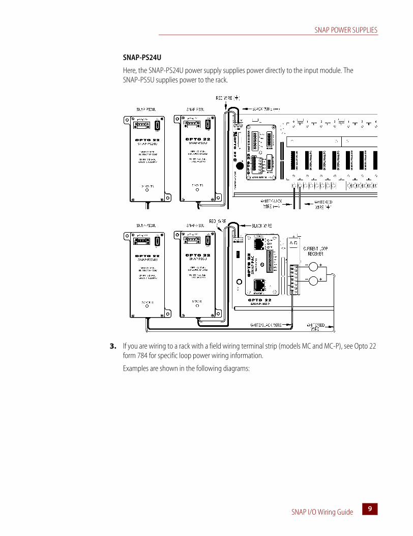
SNAP-PS24U
Here, the SNAP-PS24U power supply supplies power directly to the input module. The SNAP-PS5U supplies power to the rack.
3. If you are wiring to a rack with a field wiring terminal strip (models MC and MC-P), see Opto 22 form 784 for specific loop power wiring information.
Examples are shown in the following diagrams:
SNAP POWER SUPPLIES
SNAP I/O Wiring Guide10
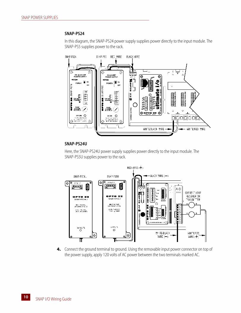
SNAP-PS24
In this diagram, the SNAP-PS24 power supply supplies power directly to the input module. The SNAP-PS5 supplies power to the rack.
SNAP-PS24U
Here, the SNAP-PS24U power supply supplies power directly to the input module. The SNAP-PS5U supplies power to the rack.
4. Connect the ground terminal to ground. Using the removable input power connector on top of the power supply, apply 120 volts of AC power between the two terminals marked AC.
SNAP PROCESSORS
SNAP I/O Wiring Guide 1111
SNAP ProcessorsRefer to “SNAP Mounting Racks” on page 2. Make certain you have a compatible processor and rack before you begin.
1. Assemble the rack, power supply, and modules according to the directions that came with them.
CAUTION: Make certain that you have the correct SNAP rack for the processor (brain or rack-mounted controller) you are using. Using the wrong rack will severely damage the processor.
2. Remove the processor from its packaging.
3. Turn off power to the rack assembly.
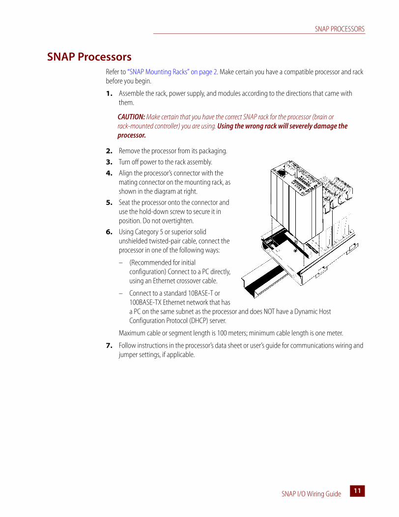
4. Align the processor’s connector with the mating connector on the mounting rack, as shown in the diagram at right.
5. Seat the processor onto the connector and use the hold-down screw to secure it in position. Do not overtighten.
6. Using Category 5 or superior solid unshielded twisted-pair cable, connect the processor in one of the following ways:
– (Recommended for initial configuration) Connect to a PC directly, using an Ethernet crossover cable.
– Connect to a standard 10BASE-T or 100BASE-TX Ethernet network that has a PC on the same subnet as the processor and does NOT have a Dynamic Host Configuration Protocol (DHCP) server.
Maximum cable or segment length is 100 meters; minimum cable length is one meter.
7. Follow instructions in the processor’s data sheet or user’s guide for communications wiring and jumper settings, if applicable.
SNAP I/O MODULES
SNAP I/O Wiring Guide12
SNAP I/O ModulesSNAP digital modules are either 4-channel or 32-channel. SNAP analog modules range from one to eight channels.
SNAP Digital Applications
Q: What is the difference between the SRC and SNK digital DC output modules?
A: SRC and SNK stand for SouRCing and SiNKing, respectively. Because one fuse is used for all four output channels on the module, Opto 22 designed two different varieties. The selection of the module type depends on which side of the load the module is placed on. Typically, a SRC module is used between the + terminal and the load, while a SNK module would be used between the load and the –, ground, or common terminal. Please note that if the wrong module is used in the wrong place, all four channels will effectively become common and all four loads will be activated if any one channel is turned on.
Q: Why is there only one digital AC output module, when there are two DC modules?
A: Only one AC module design is required, because the switching devices used in the AC module are non-polar, unlike the transistors used in the DC modules. So the AC module may be used for sourcing or sinking, as long as all four channels on the module are wired in the same way.
Q: Is there any way to get more than 0.75 A current capacity out of each channel on the digital output module?
A: Yes. SNAP digital output modules are not rated on a channel-to-channel basis; instead, the entire module is rated for a maximum of 3 A. Any one channel on the module can carry up to 3 A, as long as the total current being carried by the module is 3 A or less. Thus, two of four channels can be used to carry 1.5 A each, with two channels unused.
Q: Can I wire the channels on a SNAP digital output module in parallel to obtain a higher current rating?
A: This question is related to the question above. There really isn’t a need to wire channels in parallel, because each channel can carry up to 3 A; just be certain that the total current passing through the module is 3 A or less. Wiring the channels in parallel will not make any difference as far as performance goes; one channel will likely activate before the others and thus take up the entire load itself anyway. Parallel wiring does allow for some automatic fallback redundancy in case one channel fails open, however.
Q: Is there a SNAP digital input module for DC voltages over 32 V?
A: Yes. SNAP AC input modules may be used for DC input up to their voltage rating. For example, a SNAP IAC5 can be used to read 125 VDC input signals. Most SNAP input modules use a full-wave rectifier on the input, allowing the module to be used as an AC or DC input and making it resistant to reversed-polarity installations.
SNAP I/O MODULES
SNAP I/O Wiring Guide 1313
Q: Is there a way to read low-voltage AC signals with a SNAP input module?
A: Yes. In the same way that SNAP AC modules can be used for DC, some SNAP DC modules can be used to take low-voltage AC signals, such as the 24 VAC commonly used in HVAC systems. This is allowable with all SNAP DC modules containing a full-wave rectifier.
Q: Does Opto 22 make a SNAP digital input module for high-speed signals? Or for quadrature input use?
A: Yes, and we offer many other digital input modules as well. For a complete list, see the Opto 22 website.
Q: What sort of isolation is provided by Opto 22 SNAP digital modules?
A: SNAP digital modules are optically isolated against transient voltages to 4,000 Vrms between the field and logic connections. Input modules are isolated up to 300 VAC between each channel on the module. There is no isolation from channel to channel on most digital output modules, due to the common connection on each module for fusing purposes, but isolated output modules are available.
SNAP Analog Applications
Q: What types of SNAP analog modules are available?
A: The software-configurable SNAP analog modules handle a wide variety of signal types, including voltage, current, rate, temperature, RMS, and more. New modules are added frequently. See the Opto 22 website for models and specifications.
Q: What type of resolution do SNAP analog inputs provide?
A: SNAP analog input modules have a typical resolution of ±25,000 counts. This equates to roughly 14.5-bit resolution plus sign, or 15.5-bit full-scale resolution. These odd resolutions are a result of the inherent accuracy of the input amplifiers used to buffer the analog-to-digital converter from the signal source. While the analog-to-digital converter may be capable of providing higher resolution numbers, they are essentially useless because of the precision level of the signal conditioning circuitry and the amount of noise inherent in any electrical signal.
Q: What type of resolution do SNAP analog output modules achieve?
A: SNAP analog outputs are 12-bit resolution, yielding 4,095 counts from zero to full-scale.
Q: How much isolation do SNAP analog modules provide?
A: SNAP analog modules are transformer and optically isolated to 4,000 Vrms between the module and the rack/brain. Most SNAP analog modules are not isolated between channels; the channels share a common return connection. However, isolated analog modules are available.
SNAP I/O MODULES
SNAP I/O Wiring Guide14
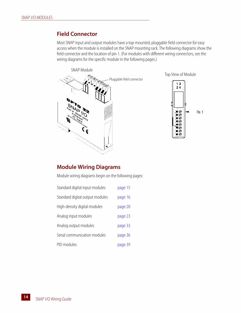
Field Connector
Most SNAP input and output modules have a top-mounted, pluggable field connector for easy access when the module is installed on the SNAP mounting rack. The following diagrams show the field connector and the location of pin 1. (For modules with different wiring connectors, see the wiring diagrams for the specific module in the following pages.)
Module Wiring Diagrams
Module wiring diagrams begin on the following pages:
Standard digital input modules page 15
Standard digital output modules page 16
High-density digital modules page 20
Analog input modules page 23
Analog output modules page 33
Serial communication modules page 36
PID modules page 39
Pluggable field connector
SNAP ModuleTop View of Module
SNAP I/O MODULES
SNAP I/O Wiring Guide 1515
Standard Digital Input Modules
For high-density digital modules, see page 20.
Wiring for most standard digital input modules (except SNAP-IDC5-SW and SNAP-IDC5-SW-NC)
Wiring for SNAP-IDC5-SW and SNAP-IDC5-SW-NC digital input modules
CAUTION: The SNAP-IDC5-SW and SNAP-IDC5-SW-NC inputs are not intended to be used with contacts that are connected to any external user-supplied voltage or currents.
SNAP I/O MODULES
SNAP I/O Wiring Guide16
Standard Digital Output Modules
For high-density digital modules, see page 20.
Wiring for SNAP-OAC5 and SNAP-OAC5FM digital AC output modules
Wiring for SNAP-OAC5MA and SNAP-OAC5-i digital AC output modules
NOTE: Each output should be fused.
SNAP I/O MODULES
SNAP I/O Wiring Guide 1717
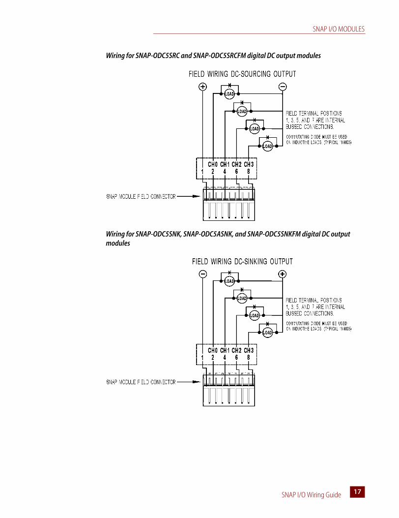
Wiring for SNAP-ODC5SRC and SNAP-ODC5SRCFM digital DC output modules
Wiring for SNAP-ODC5SNK, SNAP-ODC5ASNK, and SNAP-ODC5SNKFM digital DC output modules
SNAP I/O MODULES
SNAP I/O Wiring Guide18
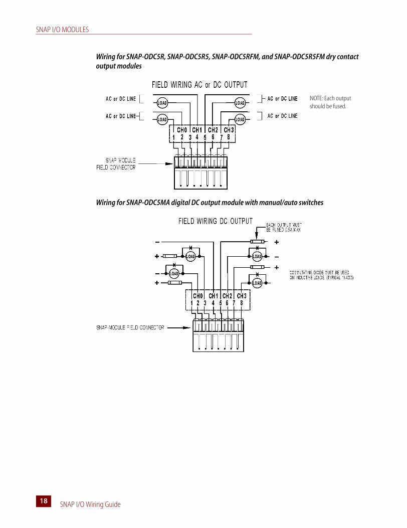
Wiring for SNAP-ODC5R, SNAP-ODC5R5, SNAP-ODC5RFM, and SNAP-ODC5R5FM dry contact output modules
Wiring for SNAP-ODC5MA digital DC output module with manual/auto switches
NOTE: Each output should be fused.
SNAP I/O MODULES
SNAP I/O Wiring Guide 1919
Wiring for SNAP-ODC5-i, SNAP-ODC5A-i, SNAP-ODC5-iFM, and SNAP-ODC5A-iFM isolated digital DC output modules
SNAP I/O MODULES
SNAP I/O Wiring Guide20
High-Density Digital Modules
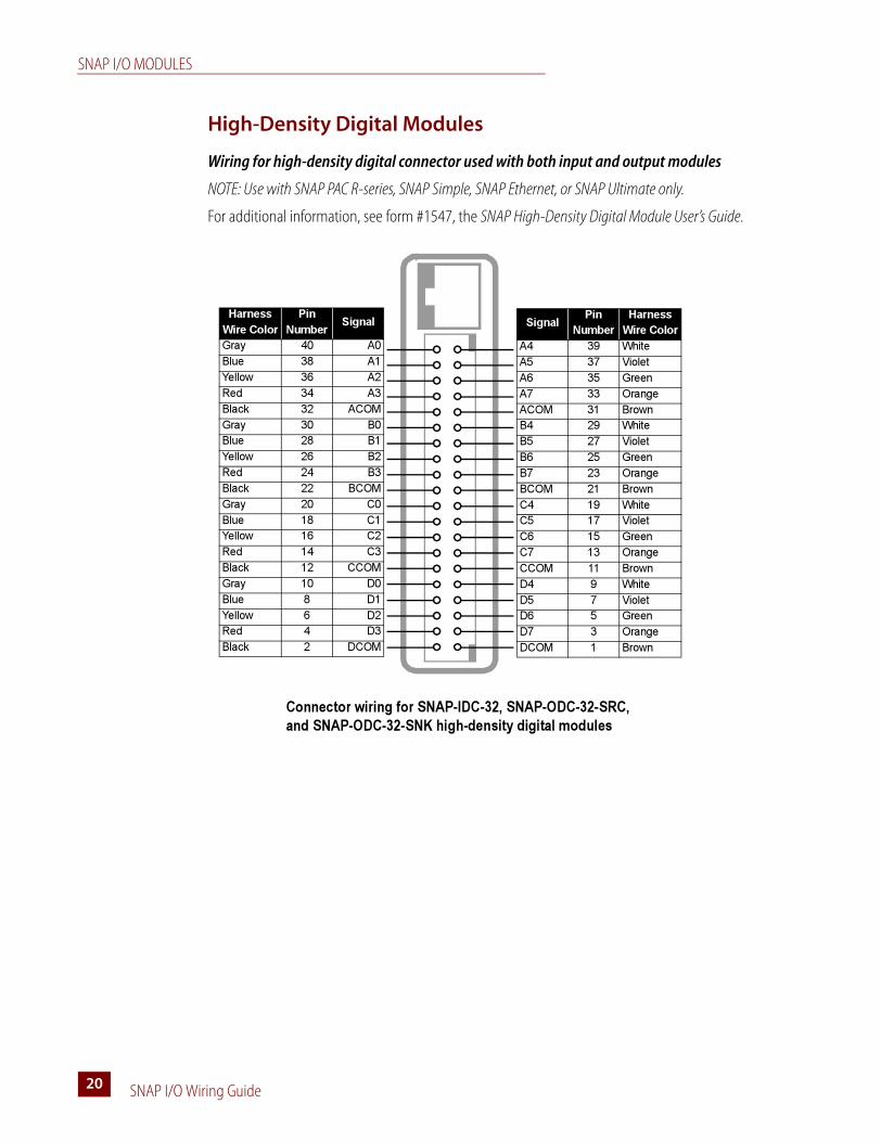
Wiring for high-density digital connector used with both input and output modules
NOTE: Use with SNAP PAC R-series, SNAP Simple, SNAP Ethernet, or SNAP Ultimate only.
For additional information, see form #1547, the SNAP High-Density Digital Module User’s Guide.
Signal
Pin
Number
Harness
Wire Color
A4 39 White
A5 37 Violet
A6 35 Green
A7 33 Orange
ACOM 31 Brown
B4 29 White
B5 27 Violet
B6 25 Green
B7 23 Orange
BCOM 21 Brown
C4 19 White
C5 17 Violet
C6 15 Green
C7 13 Orange
CCOM 11 Brown
D4 9 White
D5 7 Violet
D6 5 Green
D7 3 Orange
DCOM 1 Brown
Harness
Wire Color
Pin
Number
Signal
Gray 40 A0
Blue 38 A1
Yellow 36 A2
Red 34 A3
Black 32 ACOM
Gray 30 B0
Blue 28 B1
Yellow 26 B2
Red 24 B3
Black 22 BCOM
Gray 20 C0
Blue 18 C1
Yellow 16 C2
Red 14 C3
Black 12 CCOM
Gray 10 D0
Blue 8 D1
Yellow 6 D2
Red 4 D3
Black 2 DCOM
Connector wiring for SNAP-IDC-32, SNAP-ODC-32-SRC,
and SNAP-ODC-32-SNK high-density digital modules
SNAP I/O MODULES
SNAP I/O Wiring Guide 2121
Wiring for SNAP-IDC-32 high-density digital input
NOTE: Use with SNAP PAC R-series, SNAP Simple, SNAP Ethernet, or SNAP Ultimate only.
Also see wiring for connector on page 20.
B0
B4
B1
B5
B2
B6
B3
B7
BCOM
10–32 VDC
C0
C4
C1
C5
C2
C6
C3
C7
CCOM10–32 VDC
D0
D4
D1
D5
D2
D6
D3
D7
DCOM10–32 VDC
A0
A4
A1
A5
A2
A6
A3
A7
ACOM
+
10–32 VDC
+
+
+
SNAP-IDC-32
High-Density Input Module
SNAP I/O MODULES
SNAP I/O Wiring Guide22
Wiring for SNAP-ODC-32-SNK and SNAP-ODC-32-SRC high-density digital outputs
NOTE: Use with SNAP PAC R-series, SNAP Simple, SNAP Ethernet, or SNAP Ultimate only.
Also see wiring for connector on page 20.
B0
B4
B1
B5
B2
B6
B3
B7
BCOM
12–24 VDC
C0
C4
C1
C5
C2
C6
C3
C7
CCOM
12–24 VDC
D0
D4
D1
D5
D2
D6
D3
D7
DCOM
12–24 VDC
A0
A4
A1
A5
A2
A6
A3
A7
ACOM+
12–24 VDC
+
+
+
B0
B4
B1
B5
B2
B6
B3
B7
BCOM
12–24 VDC
C0
C4
C1
C5
C2
C6
C3
C7
CCOM
12–24 VDC
D0
D4
D1
D5
D2
D6
D3
D7
DCOM
12–24 VDC
A0
A4
A1
A5
A2
A6
A3
A7
ACOM
+
12–24 VDC
LOAD
LOA
LOA
LOA
LOA
LOA
LOA
LOA
LOA
LOA
LOA
LOA
LOA
LOA
LOA
LOA
LOA
LOA
LOA
LOA
LOA
LOA
LOA
LOA
LOA
LOA
LOA
LOA
LOA
LOA
LOA
LOA
SNAP-ODC-32-SRC
Load Sourcing Module
SNAP-ODC-32-SNK
Load Sinking Module
+
+
+
LOAD
LOAD
LOAD
LOAD
LOAD
LOAD
LOAD
LOAD
LOA
LOA
LOA
LOA
LOA
LOA
LOA
LOAD
LOAD
LOAD
LOAD
LOAD
LOAD
LOAD
LOA
LOA
LOA
LOA
LOA
LOA
LOA
LOA
LOAD
LOA
LOA
LOA
LOA
LOA
LOA
LOA
LOAD
LOAD
LOAD
LOAD
LOAD
LOAD
LOAD
LOA
LOA
LOA
LOA
LOA
LOA
LOA
LOA
LOA
LOA
LOA
LOA
LOA
LOA
LOA
LOA
LOAD
LOA
LOA
LOA
LOA
LOA
LOA
LOA
LOAD
LOAD
LOAD
LOAD
LOAD
LOAD
LOAD
LOAD
LOA
LOA
LOA
LOA
LOA
LOA
LOA
LOA
LOA
LOA
LOA
LOA
LOA
LOA
LOA
LOA
LOA
LOA
LOA
LOA
LOA
LOA
LOA
LOA
LOA
LOA
LOA
LOA
LOA
LOA
LOA
LOAD
LOAD
LOAD
LOAD
LOAD
LOAD
LOAD
LOAD
LOA
LOA
LOA
LOA
LOA
LOA
LOA
LOAD
LOAD
LOAD
LOAD
LOAD
LOAD
LOAD
LOA
LOA
LOA
LOA
LOA
LOA
LOA
LOA
LOAD
LOA
LOA
LOA
LOA
LOA
LOA
LOA
LOAD
LOAD
LOAD
LOAD
LOAD
LOAD
LOAD
LOA
LOA
LOA
LOA
LOA
LOA
LOA
LOA
LOA
LOA
LOA
LOA
LOA
LOA
LOA
LOA
LOAD
LOA
LOA
LOA
LOA
LOA
LOA
LOA
LOAD
LOAD
LOAD
LOAD
LOAD
LOAD
LOAD
FUSING
For both sourcing and sinking
modules, use one of the two
fusing options shown in the
first two output groups below.
SNAP I/O MODULES
SNAP I/O Wiring Guide 2323
Analog Input Modules
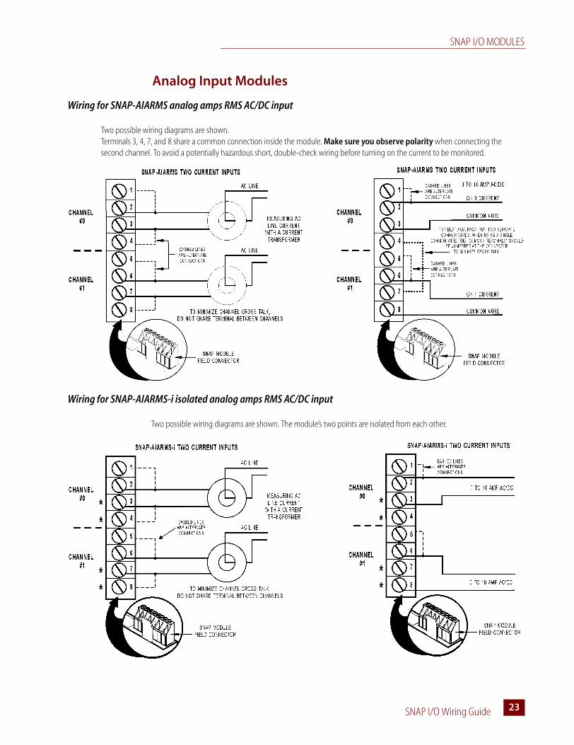
Wiring for SNAP-AIARMS analog amps RMS AC/DC input
Wiring for SNAP-AIARMS-i isolated analog amps RMS AC/DC input
Two possible wiring diagrams are shown. Terminals 3, 4, 7, and 8 share a common connection inside the module. Make sure you observe polarity when connecting the second channel. To avoid a potentially hazardous short, double-check wiring before turning on the current to be monitored.
Two possible wiring diagrams are shown. The module’s two points are isolated from each other.
SNAP I/O MODULES
SNAP I/O Wiring Guide24
Wiring for SNAP-AIVRMS analog volts RMS AC/DC input
Wiring for SNAP-AIVRMS-i isolated analog volts RMS AC/DC input
Terminals 3, 4, 7, and 8 share a common connection inside the module. Make sure you observe polarity when connecting the second channel. To avoid a potentially hazardous short, double-check wiring before turning on the voltage to be monitored.
The two points on the SNAP-AIVRMS-i are isolated from each other.
SNAP I/O MODULES
SNAP I/O Wiring Guide 2525
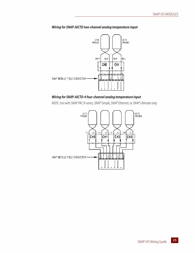
Wiring for SNAP-AICTD two-channel analog temperature input
Wiring for SNAP-AICTD-4 four-channel analog temperature input
NOTE: Use with SNAP PAC R-series, SNAP Simple, SNAP Ethernet, or SNAP Ultimate only.
SNAP I/O MODULES
SNAP I/O Wiring Guide26
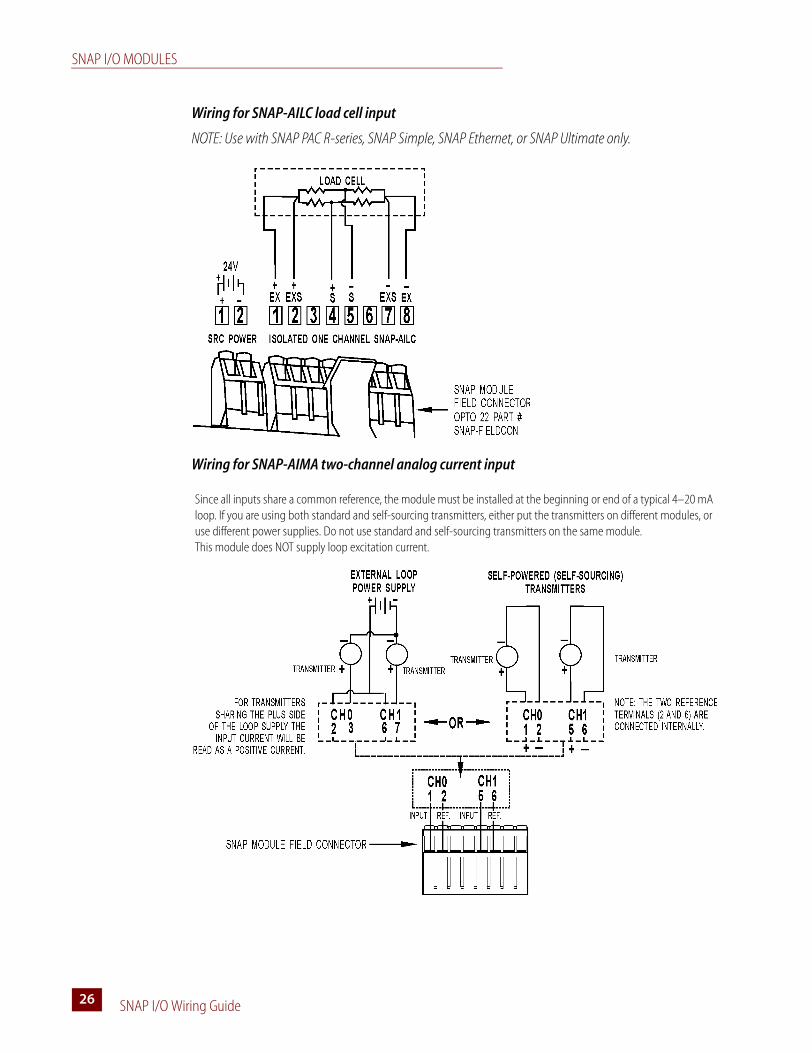
Wiring for SNAP-AILC load cell input
NOTE: Use with SNAP PAC R-series, SNAP Simple, SNAP Ethernet, or SNAP Ultimate only.
Wiring for SNAP-AIMA two-channel analog current input
Since all inputs share a common reference, the module must be installed at the beginning or end of a typical 4–20 mA loop. If you are using both standard and self-sourcing transmitters, either put the transmitters on different modules, or use different power supplies. Do not use standard and self-sourcing transmitters on the same module.This module does NOT supply loop excitation current.
SNAP I/O MODULES
SNAP I/O Wiring Guide 2727
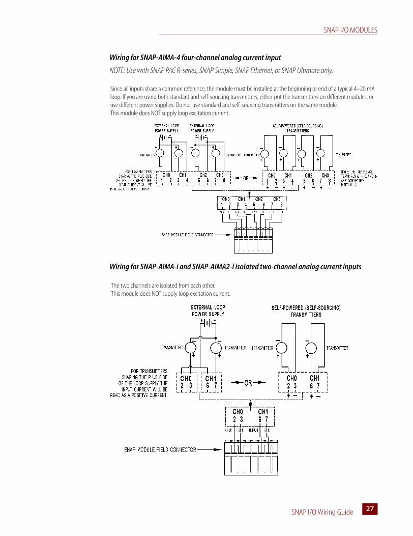
Wiring for SNAP-AIMA-4 four-channel analog current input
NOTE: Use with SNAP PAC R-series, SNAP Simple, SNAP Ethernet, or SNAP Ultimate only.
Wiring for SNAP-AIMA-i and SNAP-AIMA2-i isolated two-channel analog current inputs
Since all inputs share a common reference, the module must be installed at the beginning or end of a typical 4–20 mA loop. If you are using both standard and self-sourcing transmitters, either put the transmitters on different modules, or use different power supplies. Do not use standard and self-sourcing transmitters on the same module.This module does NOT supply loop excitation current.
The two channels are isolated from each other. This module does NOT supply loop excitation current.
SNAP I/O MODULES
SNAP I/O Wiring Guide28
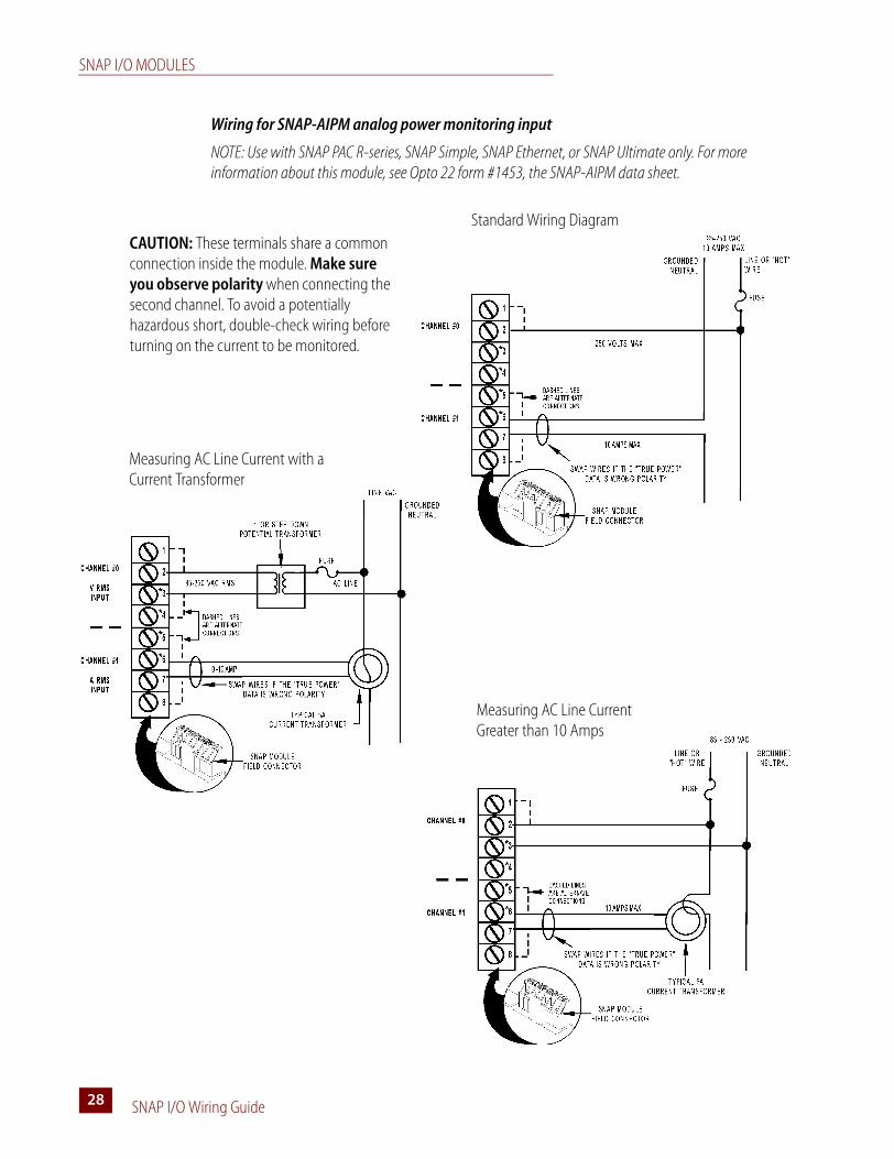
Wiring for SNAP-AIPM analog power monitoring input
NOTE: Use with SNAP PAC R-series, SNAP Simple, SNAP Ethernet, or SNAP Ultimate only. For more information about this module, see Opto 22 form #1453, the SNAP-AIPM data sheet.
Standard Wiring Diagram
Measuring AC Line Current with a Current Transformer
Measuring AC Line Current Greater than 10 Amps
CAUTION: These terminals share a common connection inside the module. Make sure you observe polarity when connecting the second channel. To avoid a potentially hazardous short, double-check wiring before turning on the current to be monitored.
SNAP I/O MODULES
SNAP I/O Wiring Guide 2929
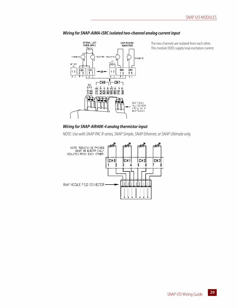
Wiring for SNAP-AIMA-iSRC isolated two-channel analog current input
Wiring for SNAP-AIR40K-4 analog thermistor input
NOTE: Use with SNAP PAC R-series, SNAP Simple, SNAP Ethernet, or SNAP Ultimate only.
The two channels are isolated from each other. This module DOES supply loop excitation current.
SNAP I/O MODULES
SNAP I/O Wiring Guide30
Wiring for SNAP-AIRATE analog rate input
Wiring for SNAP-AIMV-4 and AIMV2-4 analog millivolt inputs
NOTE: Use with SNAP PAC R-series, SNAP Simple, SNAP Ethernet, or SNAP Ultimate only.
Two possible wiring diagrams are shown:
SNAP I/O MODULES
SNAP I/O Wiring Guide 3131
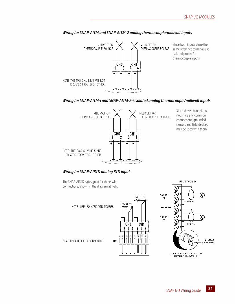
Wiring for SNAP-AITM and SNAP-AITM-2 analog thermocouple/millivolt inputs
Wiring for SNAP-AITM-i and SNAP-AITM-2-i isolated analog thermocouple/millivolt inputs
Wiring for SNAP-AIRTD analog RTD input
Since both inputs share the same reference terminal, use isolated probes for thermocouple inputs.
Since these channels do not share any common connections, grounded sensors and field devices may be used with them.
The SNAP-AIRTD is designed for three-wire connections, shown in the diagram at right.
SNAP I/O MODULES
SNAP I/O Wiring Guide32
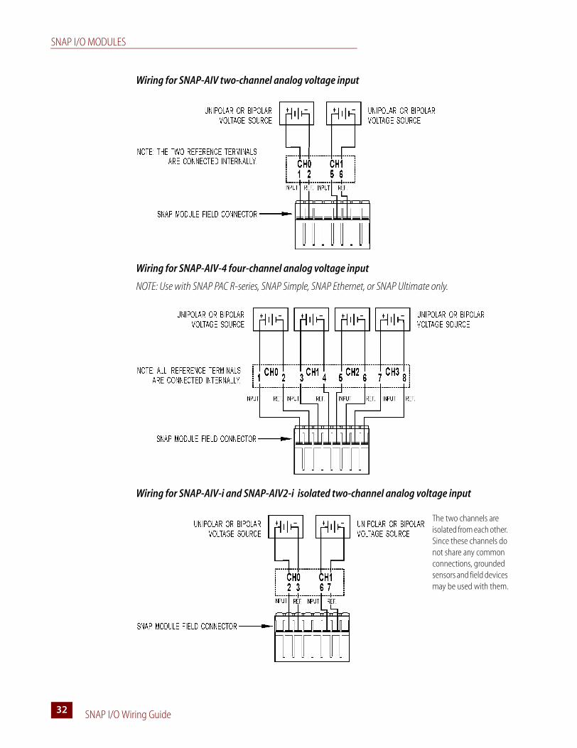
Wiring for SNAP-AIV two-channel analog voltage input
Wiring for SNAP-AIV-4 four-channel analog voltage input
NOTE: Use with SNAP PAC R-series, SNAP Simple, SNAP Ethernet, or SNAP Ultimate only.
Wiring for SNAP-AIV-i and SNAP-AIV2-i isolated two-channel analog voltage input
The two channels are isolated from each other. Since these channels do not share any common connections, grounded sensors and field devices may be used with them.
SNAP I/O MODULES
SNAP I/O Wiring Guide 3333
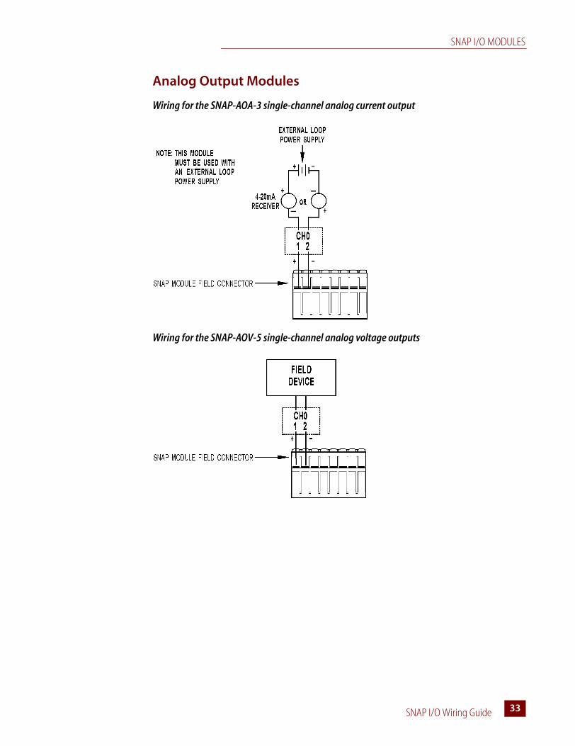
Analog Output Modules
Wiring for the SNAP-AOA-3 single-channel analog current output
Wiring for the SNAP-AOV-5 single-channel analog voltage outputs
SNAP I/O MODULES
SNAP I/O Wiring Guide34
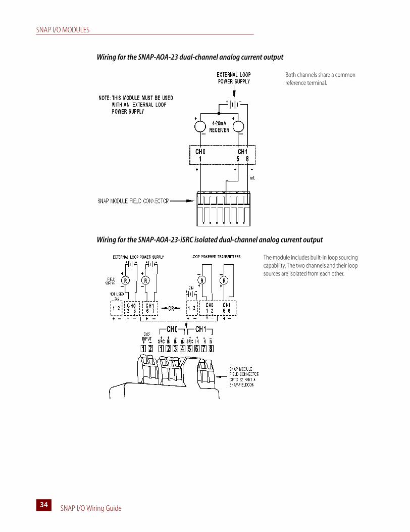
Wiring for the SNAP-AOA-23 dual-channel analog current output
Wiring for the SNAP-AOA-23-iSRC isolated dual-channel analog current output
Both channels share a common reference terminal.
The module includes built-in loop sourcing capability. The two channels and their loop sources are isolated from each other.
SNAP I/O MODULES
SNAP I/O Wiring Guide 3535
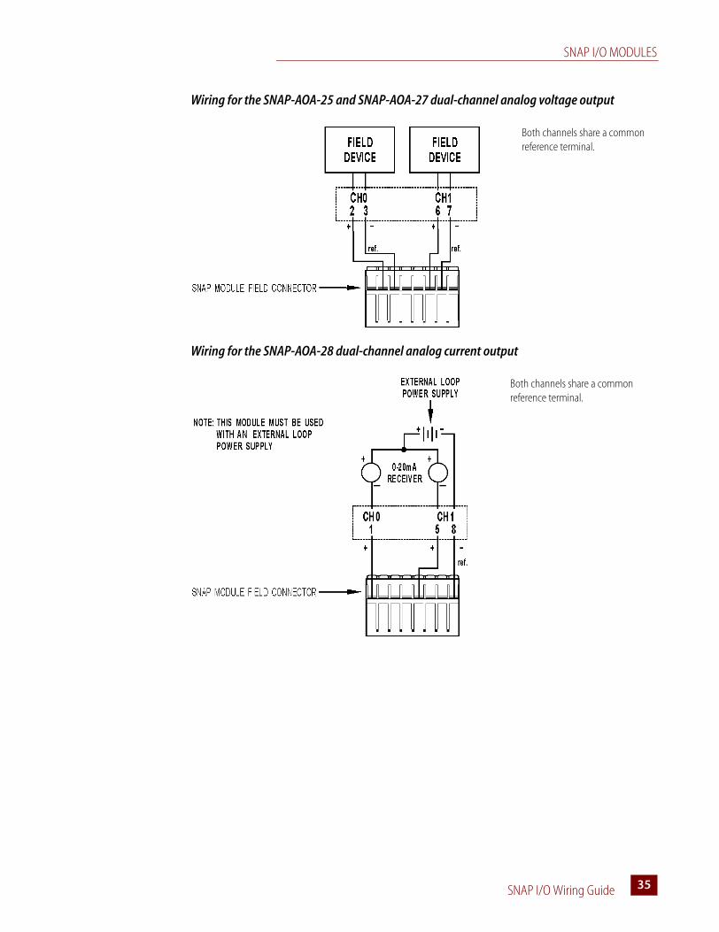
Wiring for the SNAP-AOA-25 and SNAP-AOA-27 dual-channel analog voltage output
Wiring for the SNAP-AOA-28 dual-channel analog current output
Both channels share a common reference terminal.
Both channels share a common reference terminal.
SNAP I/O MODULES
SNAP I/O Wiring Guide36
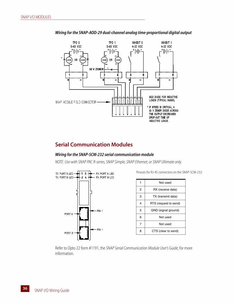
Wiring for the SNAP-AOD-29 dual-channel analog time-proportional digital output
Serial Communication Modules
Wiring for the SNAP-SCM-232 serial communication module
NOTE: Use with SNAP PAC R-series, SNAP Simple, SNAP Ethernet, or SNAP Ultimate only.
Refer to Opto 22 form #1191, the SNAP Serial Communication Module User’s Guide, for more information.
Pinouts for RJ-45 connectors on the SNAP-SCM-232:
1 Not used
2 RX (receive data)
3 TX (transmit data)
4 RTS (request to send)
5 GND (signal ground)
6 Not used
7 Not used
8 CTS (clear to send)
SNAP I/O MODULES
SNAP I/O Wiring Guide 3737
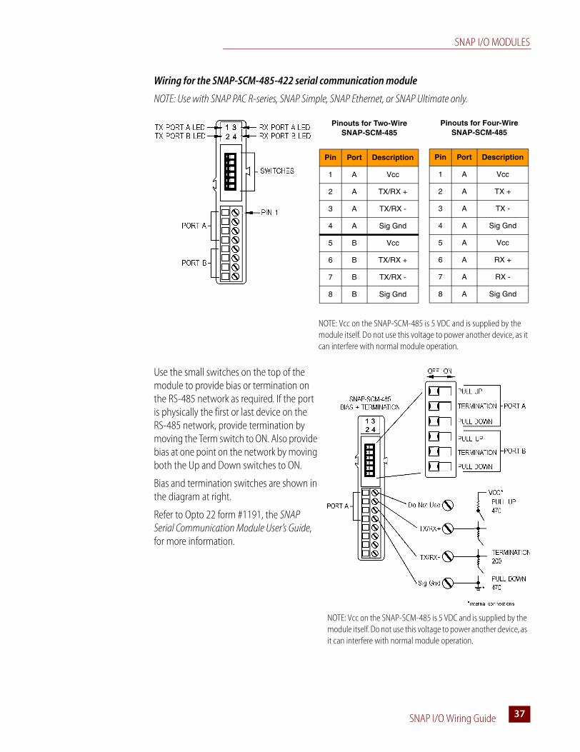
Wiring for the SNAP-SCM-485-422 serial communication module
NOTE: Use with SNAP PAC R-series, SNAP Simple, SNAP Ethernet, or SNAP Ultimate only.
Use the small switches on the top of the module to provide bias or termination on the RS-485 network as required. If the port is physically the first or last device on the RS-485 network, provide termination by moving the Term switch to ON. Also provide bias at one point on the network by moving both the Up and Down switches to ON.
Bias and termination switches are shown in the diagram at right.
Refer to Opto 22 form #1191, the SNAP Serial Communication Module User’s Guide, for more information.
NOTE: Vcc on the SNAP-SCM-485 is 5 VDC and is supplied by the module itself. Do not use this voltage to power another device, as it can interfere with normal module operation.
Pinouts for Two-Wire SNAP-SCM-485
Pin Port Description
1 A Vcc
2 A TX/RX +
3 A TX/RX -
4 A Sig Gnd
5 B Vcc
6 B TX/RX +
7 B TX/RX -
8 B Sig Gnd
Pinouts for Four-Wire SNAP-SCM-485
Pin Port Description
1 A Vcc
2 A TX +
3 A TX -
4 A Sig Gnd
5 A Vcc
6 A RX +
7 A RX -
8 A Sig Gnd
NOTE: Vcc on the SNAP-SCM-485 is 5 VDC and is supplied by the module itself. Do not use this voltage to power another device, as it can interfere with normal module operation.
SNAP I/O MODULES
SNAP I/O Wiring Guide38
Wiring for the SNAP-SCM-PROFI serial communication module
NOTE: Use with SNAP PAC R-series, SNAP Simple, SNAP Ethernet, or SNAP Ultimate only.
Communication switches are shown in the diagram at right. If you are using an official PROFIBUS cable, termination is provided in the cable; therefore, switch the termination to ON in the cable and move the Term switch to OFF in the SNAP-SCM-PROFI module.
See the SNAP Serial Communication Module User’s Guide (form #1191) for more information.
Wiring for the SNAP-SCM-W2 serial communication module
NOTE: Use with SNAP PAC R-series, SNAP Ethernet, or SNAP Ultimate only.
SNAP-SCM-PROFI Top View
Switches
PowerReceive
RunTransmit
OFF ON
Pull Up ResistorPull Down ResistorTermination
Not UsedSerial Port
Communication
Pinouts for SNAP-SCM-W2
Pin Port Color Description
1 A Black Common
2 A White Data One
3 A Green Data Zero
4 A -- Not used
5 B Black Common
6 B White Data One
7 B Green Data Zero
8 B -- Not used
SNAP-SCM-W2 Top View
SNAP I/O MODULES
SNAP I/O Wiring Guide 3939
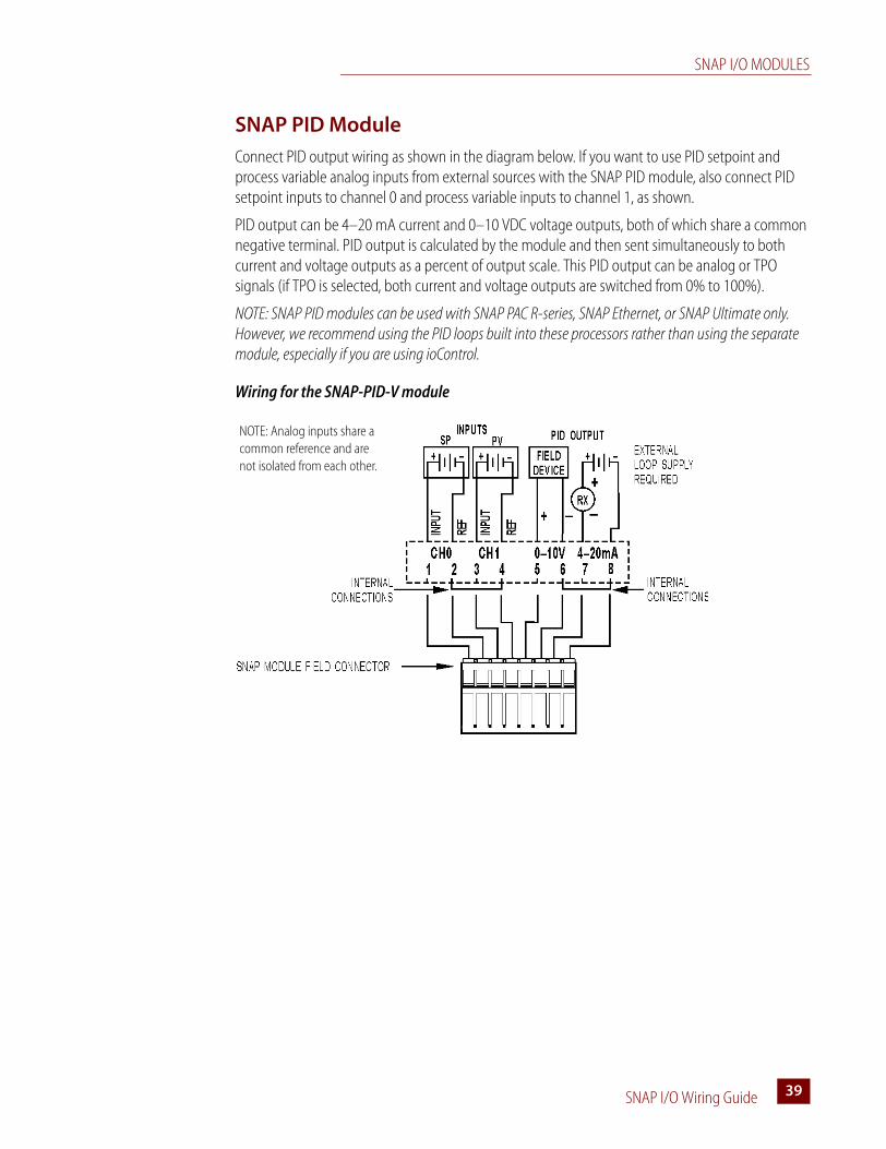
SNAP PID Module
Connect PID output wiring as shown in the diagram below. If you want to use PID setpoint and process variable analog inputs from external sources with the SNAP PID module, also connect PID setpoint inputs to channel 0 and process variable inputs to channel 1, as shown.
PID output can be 4–20 mA current and 0–10 VDC voltage outputs, both of which share a common negative terminal. PID output is calculated by the module and then sent simultaneously to both current and voltage outputs as a percent of output scale. This PID output can be analog or TPO signals (if TPO is selected, both current and voltage outputs are switched from 0% to 100%).
NOTE: SNAP PID modules can be used with SNAP PAC R-series, SNAP Ethernet, or SNAP Ultimate only. However, we recommend using the PID loops built into these processors rather than using the separate module, especially if you are using ioControl.
Wiring for the SNAP-PID-V module
NOTE: Analog inputs share a common reference and are not isolated from each other.
SNAP I/O MODULES
SNAP I/O Wiring Guide40
SNAP I/O Wiring Guide 4141
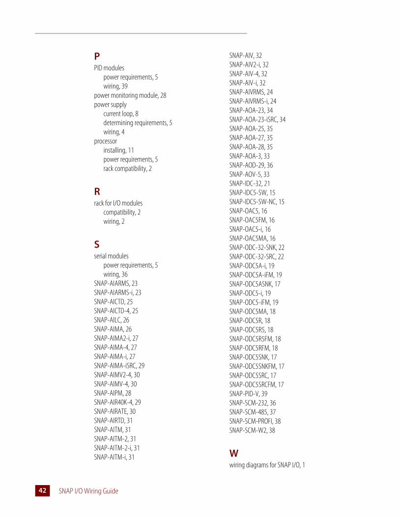
Index
Aanalog input modules
power requirements, 5wiring, 23
analog output modulespower requirements, 5wiring, 33