SANDRA Final Report 1 SANDRA PROJECT FINAL REPORT Publishable Summary Grant Agreement number: 233679 Project acronym: SANDRA Project title: SEAMLESS AERONAUTICAL NETWORKING THROUGH INTEGRATION OF DATA LINKS, RADIOS AND ANTENNAS Funding Scheme: Collaborative Project (CP) - Large-scale integrating project (IP) Period covered: from September 2009 to December 2013 Name of the scientific representative of the project's co-ordinator 1 , Title and Organisation: Paolo DI MICHELE, Project Coordinator, Selex ES Tel: +39 06 41504850 Fax: E-mail: [email protected]Massimiliano AMIRFEIZ, Project Technical Coordinator, Selex ES Tel: +39 010 6145517 Fax: +39 010 6145714 E-mail: [email protected]Project website address: www.sandra.aero 1 Usually the contact person of the coordinator as specified in Art. 8.1. of the Grant Agreement.
Transcript
SANDRA Final Report
1
SANDRA PROJECT FINAL REPORT
Publishable Summary
Grant Agreement number: 233679
Project acronym: SANDRA
Project title: SEAMLESS AERONAUTICAL NETWORKING THROUGH INTEGRATION OF
1 Usually the contact person of the coordinator as specified in Art. 8.1. of the Grant Agreement.
SANDRA Final Report
2
Contents
1. Executive summary 3
2. Project context and objectives 4
3. Main S&T results/foregrounds 6 a Requirements and global system architecture 6 b Seamless Networking 10 c Integrated Modular Radio 14 d Integrated Antenna System 19 e Global Airport Connectivity 26 f Trials and Validation 30
4. Potential Impact & dissemination activities 34
5. Project public website & contacts 45
6. List of beneficiaries 45
SANDRA Final Report
3
1. Executive summary
Digital communication systems are an everyday routine for more and more passengers, but pilots
are largely cut off from this development. This is because, up until now, they have had to
communicate using a completely separate system that is primarily analogue. With smartphones, we
have been used to surfing the Internet when we are travelling, using the cheapest possible
connection available, be it WLAN, the mobile network or via Bluetooth. It is precisely this flexibility
that is also required in the new approach to aircraft communications.
Tx is a triggered by system (periodic or not) transparent to the crew
Rx can occur at any time / is active all the time
Tx is active only upon aircraft user action
Rx occurs only in response to a Tx within appropriate timeframe
Inhibited use
1 Tx/Rx can not be missed/delayed/interrupted
2 Tx/Rx can not be delayed by more than seconds (<10)
3 Tx/Rx can not be delayed by more than minutes (<5)
4
Tx/Rx can be delayed and/or interrupted in order to free bandwidth/resources for higher
priority services
Blank cell : N/A or no operational use
Table 1: Example link usage apportionment for Business Jet scenario
SANDRA Final Report
9
The same approach has been follow for the commercial airliner scenario as well as the UAS
environment presented on Figure 4 below.
Figure 4: UAS data links
Based on this analysis, the system architecture has been consolidated taking into account the
outcome of the activities performed in the other subprojects of SANDRA. Multiple scenarios for the
transition between the current systems and future architectures integrating the SANDRA concept
have been studied. The impact of the SANDRA system integration both onboard the aircraft but also
in terms of ground infrastructure and role players has been analysed.
Figure 5 illustrates the overall system architecture identifying all the main components involved in
providing the services to the users.
Onboard, the users of the SANDRA system are, all the classical ATS and AOC applications but also
the SWIM airborne middleware currently under definition and potentially all “connected equipment”
such as non-critical cockpit equipment (e.g. EFB, …) and passenger equipment (e.g. laptops, PDA,
…).
On the ground side, the SANDRA system provides services to either national or regional ANSPs but
also the Airlines and classical Internet Service Providers allowing them to provide services to either
their onboard counterpart or directly to passengers.
SANDRA Final Report
10
Figure 5: Overall System Architecture Overview
b Seamless Networking
There is a need for a new approach in order to achieve the aforementioned broader level of
integration for the required increase of capacity, safety, security, and efficiency of air transportation
operations which keeps at the same time the complexity and cost of on-board networks and
equipment within a sustainable level. As spotlighted above, there are many attempts to reach the
goal of a future worldwide seamless networking in aeronautical communications within the next
decades. The SANDRA project supports the achievement of this objective in:
• Defining, integrating, and validating a reference communications architecture directly related
to the service oriented avionics architecture envisioned by the Future Communications
Study;
• Establishing the feasibility of integration the SESAR concepts into the overall
communications system of future airliner;
• Taking into account the integration of all communications domains (ATS, AOC/AAC, APC) to
pursue economic efficiency and robustness in critical situations;
• Integration of the existing and future network technologies including the interfaces to
integrated radio technologies (VHF, AeroMACS, L-band, and Ku-band);
• Speeding up research and standardization.
For these goals the SANDRA integrated network concept with IPv6 as final unification point (target
2025 and beyond) is developed. The overall SANDRA network structure is shown in Figure 1.
The integration of different service domains with very heterogeneous requirements through a cost-
effective and flexible avionic architecture is thus one of the main challenges addressed by
SANDRA. Under this perspective, the SANDRA communications system presents a key to enable
SANDRA Final Report
11
the global provision of distributed services for common decision making based on the SWIM
concept, and to meet the high market demand for broadband passenger and enhanced cabin
communications services.
Network Architecture and Interoperability
Before the definition of a new network structure can start a detailed consolidation of existing and on-
going network and system requirements is needed. The definition of a functional architecture for
such a complex system aims at integrating the major network functions and the message
exchanges between main functions. Hence, a description of the data exchange for the data plane,
the control plane, and the management plane is needed. Furthermore, a specification of the
characteristics depending on the type of services is required in the data plane, e.g., quality-of-
service (QoS) management, link or traffic profile characteristics.
Figure 6: Illustration of the basic communication architecture model
Middleware and Service Integration
Based on SESAR’s vision, future airborne systems will interoperate with ground systems by using a
SWIM airborne side middleware instance. The possibility of an extension of SWIM capabilities
towards the integration of different domains is investigated in SANDRA. In addition, SWIM is very
bandwidth demanding which can be hardly offered by current data links for airborne/ground service.
Therefore, SANDRA adds a new airborne part, called SANDRA Airborne Middleware (SAM), to the
SWIM concept which takes into account legacy data links and future data links. Main task of SAM is
the translation of SWIM information to a compressed information-complete format which can be fed
through the existing and future data links. SAM is compliant with the overall SWIM concept, and
therefore, an air-ground service is enabled to the SWIM ground middleware.
Global Security Concept
Future safety related communication as in aeronautics will require a security concept handling
threats and attacks to the system. The SANDRA security concept removes the segregation between
different services (ATC, AOC, AAC, APC), as existing today. This is in line with SESAR’s AOC
Study stating the old segregation of ATC / AOC and AAC and APC is fading. The security concept is
SANDRA Final Report
12
approached by the view on two subsystems: the ground and the airborne system. Furthermore,
assets identification, threat scenarios, risk estimation, and risk treatment were identified and
developed. Within the SANDRA project network-based security issues were investigated on Layer 3
with the focus on IPv6.
Network Design
Since IPv6 is the unification point in the SANDRA network, there is the need of design and
adaptation of the network infrastructure to an aeronautical internet. One focus within this task is the
handling of network management and also of resource and QoS management. Additionally, effort is
spent for the development of new and efficient handover and mobility management algorithms and
concepts, respectively. Also an IPv6 based naming and addressing architecture is provided. In the
following a selection of results are highlighted.
For the SANDRA Terminal, the lower layer (link and physical layer) functions are provided by an on-
board IMR consisting of heterogeneous radio access technologies. The upper layer (layer 3 and
above) functions are managed by an IR. The interface between these two entities is realized by the
use of the IEEE 802.21 MIH (media-independent handover) framework and an extension of the
ETSI BSM (broadband satellite multimedia) SI-SAP concept. Thus, the combined usage of both
standards considers the separation of technology-independent upper layers from technology-
dependent lower layers to enable interoperability among heterogeneous networks.
Figure 7: SANDRA IP network protocol stack
Work on IPv6 network mobility (NEMO) protocol is done due to the high degree of mobility on a
global scale and the heterogeneous network environment consisting of short-range and long-range
terrestrial as well as satellite access technologies. The mobility concept is based on a mobile router,
located in the aircraft, performing handovers between access routers in the different access
networks and geographical areas, e.g. on the American or the European continent.
SANDRA Final Report
13
In terms of naming and addressing the main outcomes are: (a) one or multiple IPv6 prefixes can be
assigned to one aircraft; (b) the same system can support multiple IPv6 prefixes; and (c) it is
envisioned to have a provider dependent prefix for the Pax System and ICAO standard prefixes for
avionics and aircraft systems.
Additional novelties towards the network design as findings of SANDRA are: (a) development of a
new security and signalling mechanism called Secure NEMO Route Optimization (SeNERO)
protocol to Mobile NEMO tunnels as a route optimization solution; (b) introduction of Robust Header
Compression (RoHC) techniques; (c) implementation of a new transport protocol called Reliable
Aeronautical Services Protocol (RASP) providing a reliable data transport for message-based
applications such as ATM services; and (d) proposing XCP (eXplicit Congestion Protocol) for
avoiding congestion and optimizing link usage.
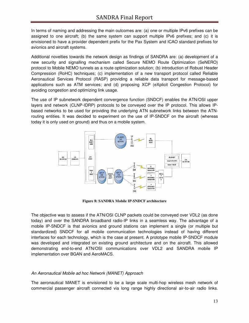
The use of IP subnetwork dependent convergence function (SNDCF) enables the ATN/OSI upper
layers and network (CLNP-IDRP) protocols to be conveyed over the IP protocol. This allows IP-
based networks to be used for providing the underlying ATN subnetwork links between the ATN-
routing entities. It was decided to experiment on the use of IP-SNDCF on the aircraft (whereas
today it is only used on ground) and thus on a mobile system.
Figure 8: SANDRA Mobile IP-SNDCF architecture
The objective was to assess if the ATN/OSI CLNP packets could be conveyed over VDL2 (as done
today) and over the SANDRA broadband radio-IP links in a seamless way. The advantage of a
mobile IP-SNDCF is that avionics and ground stations can implement a single (or multiple but
standardized) SNDCF for all mobile communication technologies instead of having different
interfaces for each technology, which is the case at present. A prototype mobile IP-SNDCF module
was developed and integrated on existing ground architecture and on the aircraft. This allowed
demonstrating end-to-end ATN/OSI communications over VDL2 and SANDRA mobile IP
implementation over BGAN and AeroMACS.
An Aeronautical Mobile ad hoc Network (MANET) Approach
The aeronautical MANET is envisioned to be a large scale multi-hop wireless mesh network of
commercial passenger aircraft connected via long range highly directional air-to-air radio links.
SANDRA Final Report
14
Principals of MANET technologies will be applied to aeronautics, as exemplarily shown over the
North Atlantic in Figure 4. A geographic load sharing strategy fully exploiting the air-to-ground
capacity is proposed. Traffic is spread among a set of next-hop candidates based on queue
dynamics. In addition congestion-aware handover strategies are applied for load balancing the
Internet gateways.
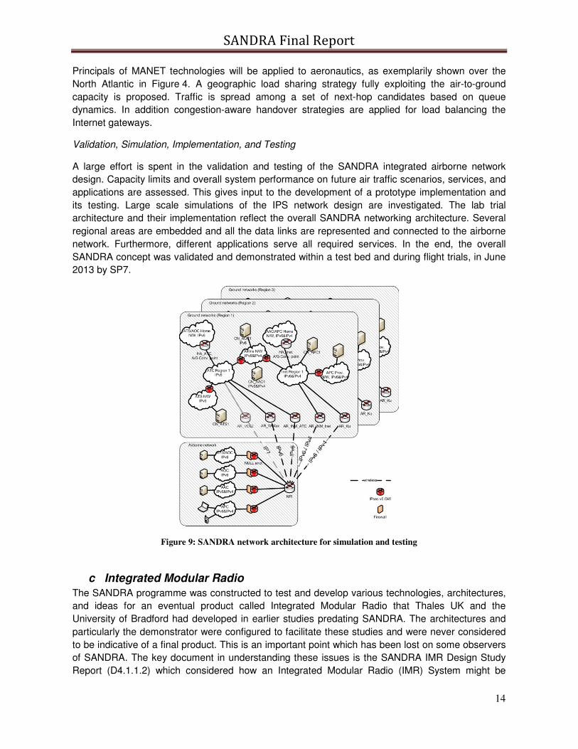
Validation, Simulation, Implementation, and Testing
A large effort is spent in the validation and testing of the SANDRA integrated airborne network
design. Capacity limits and overall system performance on future air traffic scenarios, services, and
applications are assessed. This gives input to the development of a prototype implementation and
its testing. Large scale simulations of the IPS network design are investigated. The lab trial
architecture and their implementation reflect the overall SANDRA networking architecture. Several
regional areas are embedded and all the data links are represented and connected to the airborne
network. Furthermore, different applications serve all required services. In the end, the overall
SANDRA concept was validated and demonstrated within a test bed and during flight trials, in June
2013 by SP7.
Figure 9: SANDRA network architecture for simulation and testing
c Integrated Modular Radio
The SANDRA programme was constructed to test and develop various technologies, architectures,
and ideas for an eventual product called Integrated Modular Radio that Thales UK and the
University of Bradford had developed in earlier studies predating SANDRA. The architectures and
particularly the demonstrator were configured to facilitate these studies and were never considered
to be indicative of a final product. This is an important point which has been lost on some observers
of SANDRA. The key document in understanding these issues is the SANDRA IMR Design Study
Report (D4.1.1.2) which considered how an Integrated Modular Radio (IMR) System might be
SANDRA Final Report
15
designed. It examined the general requirements and candidate architectures for such a system, and
examined them against some of the issues which affect the design choices for the equipment. A
comparison was made between the architectures. Finally two software architecture approaches
were evaluated. These were compared and contrasted and the certifiability of each was evaluated.
An IMR system is intended to be capable of providing the complete communications infrastructure
for an aircraft. The systems which are candidates for the inclusion of IMR modules include radio and
satellite communications, TCAS, ILS and many others.
Radio functionality splits into three main components:
• “The Front End” which includes antennae, HPA and DLNA;
• “Transceiver Functionality” which includes band specific RF circuits, ADC and DAC;
• “Processing Functionality” which includes DSP, channel coding protocol stack and
application.
Figure 10: Partitioning of Radio Functionality
The ability to combine functionality for the different systems in “The Front End” and “Transceiver
Functionality” is severely limited by issues such as dynamic range and co-site problems for
example. However, a large percentage of modern radio functionality is implemented in software and
by using a common processing platform development, testing and maintenance costs may be
reduced. Two main architectures have been considered to address the IMR concept. A Centralised
Architecture where the processing functionality is centralised in dedicated processing modules and
a distributed architecture where a common processing module design and implementation is used
for each of the radio modules.
SANDRA Final Report
16
Figure 11: Integrated Modular Radio SANDRA prototype, exploring IMR principles
IMR as a concept raises a number of issues. With current aviation communications systems most
are isolated from one another and have little in the way of security mechanisms. However, with an
integrated system which contains a large amount of digital signalling this is no longer the case and
security is an issue which must be addressed. Security poses a different set of problems to safety
although superficially the certification processes are similar. The IMR Design Study Report
conducted reviews of the different security initiatives being carried out within the aviation
community, which are on-going and, as yet, without a consensus of approach.
Another issue to be considered with IMR is support for Seamless Networking, including handling of
asymmetric links. While the majority of this is handled at the network level, it has an impact on the
IMR radio as a consistent interface has to be provided by all the links supporting Seamless
Networking. In a fully integrated communications system, the IMR would in all probability include
within it the network routing and resource management functions. However, as an expedient way of
partitioning the areas of responsibility and work in the SANDRA programme, the Integrated Router
was partitioned away from the IMR. The Resource Management function provides the interface
between these two areas of functionality and its function is split between the two areas. This was a
purely pragmatic decision but which affects the way in which many of the higher level functions are
considered both by SP4 and SP3. An unintended consequence of this was that the term IMR came
to mean only the SDR part of the overall communications system, whereas, previously, IMR had
included all of the routing and radio management functionality. This has led to the adoption of a new
term IMC (Integrated Modular Communications) to mean the entire system.
To provide a whole communications system by means of an IMR equipment will require the issues
such as resource and redundancy management to be addressed as well as re-configuration of the
system. Finally the largest issue is likely to be certification of such a system as the combined
system is likely to be rated at a higher DAL level than the current individual radio equipments and
hence modular or component certification mechanisms will be required.
SANDRA Final Report
17
In order to evaluate the candidate IMR architectures, the above issues were used as points of
comparison. The findings of this comparison showed that the decision as to which type of
architecture is best is not clear cut, but a choice had to be made, and the SANDRA IMR architecture
as implemented in the proof of concept demonstrator ended up being a centralised architecture.
Based on the SANDRA experience, it can be concluded that the centralised architecture worked
well, so it recommends itself as the way forward. The possibility of running multiple waveforms
concurrently on one processing platform was demonstrated, as was the provision of redundancy
and failure management.
LM-SAP
Figure 12: IMR Joint Radio Resource Manager architecture
Another key area of study was the digital bus that connects the transceivers to the baseband
processors. Here again SANDRA built on previous work. CPRI proved to be a good choice, and the
other standards that were considered (PCIe and SRIO) were shown to have been not as suitable.
The chaining of transceivers and the ability to reach a given transceiver via different routes
(important for failure management) required the implementation of a CPRI switch.
A number of lessons were learned from the detailed implementation of the radio modules:
• Defining the software application principles early on helped partners develop applications that could be integrated together.
• The use of an operating system with a process model (QNX) allowed different applications to be run concurrently.
• The definition of interfaces with other partners also worked well and this facilitated the integration of the different applications.
• Establishing the optimum priorities of the different tasks in the L-Band stack application proved troublesome but was eventually found. Several important lesson have been learnt from this experience.
During the implementation of the Radio Resource management, the following was learnt:
• Modular designs together with sufficient and clear interfaces definitions have brought invaluable benefits to the project. The JRRM had to interface with the IR, BGAN stack, DVBS2 stack, AeroMACS Proxy, VDL2 stack, Supervisor Application, Network Management Agent and Flight Status Emulator. Clear definitions of the interfaces via common set header
SANDRA Final Report
18
files sharing made it possible to develop and debug the JRRM codes independently and remotely from all the applications developments.
• Event triggered messages handling processing is essential for JRRM. Instead of checking messages in the queue periodically, all messages were processed based on queue message arrival notification events immediately. This ensures minimum JRRM processing delay and saves the CPU processing time utilised by the JRRM. For messages requiring a long time to complete, for example, the loading of waveforms, or opening a connection, internal queues are created to buffer them and process them in separate internal queue working threads.
• Multithreading, prioritisation and use of mutex are other good practises to implement complicated message processing systems.
• Reasonable usage of the configuration files makes the JRRM more flexible and general for different test scenarios and integrations. For example, Master JRRM and Slave JRRM can use identical executable but with different behaviours; the JRRM can work with or without the presence of the Supervisor for individual tests with specific radios; the JRRM can be configured to use different network addresses, interfaces; the JRRM can be configured to allow different combination of waveforms; it can be given different time out values to suit different networking working conditions; it can be instructed to load/unload different waveforms on the same flight phase; and etc.. All the above capabilities are realised by reasonable usage of configuration flags instead of hardcoding them in the software, it also saves considerable amount of time during integration with partners since there is no need to recompile the codes, but instead make a change of the flags.
• Due to the nature of the inter-processing mechanisms of the QNX POSIX messages queues, once a queue is unlinked (deleted), the listener of the queue will not be able to receive any messages from that queue without reopening the queue. Although the owners of each queue have been clearly documented, this behaviour still creates lots of problems in the early stage of the developments. So, some careful thought about the timing and usage of the unlink command is important.
• Always pay enough attention on version managements of the source codes. This will not only save time by avoiding debugging the same errors caused by obsolete pieces of code, but also ensure an efficient development and integration environment for the whole project.
The interface between the JRRM and Supervisor worked, with the Supervisor monitoring the health
of those waveforms / applications that it had launched, either autonomously or at the request of the
JRRM. The Supervisor correctly restarted waveforms that had failed but were still required by the
JRRM, and removed those waveforms no longer in use.
A disappointment was the time it took to launch the waveforms; which resulted in delays between
starting a physical layer and the waveform/stack being launched. This was, in part, necessitated by
the need to ensure that the queues had been created in time. This has implications for handover in
situations where a waveform crashes, or when an CPU crashes and the IMR/IR has to handover.
Seamless transfers when all waveforms are running is achieved by the JRRM starting the waveform
intended to take an existing 'stream' being started sufficiently ahead of ceasing to use the waveform
currently handling that stream.
Finally, the report Avionics Integration (D4.1.2.1) detailed the investigation of how an IMR might be
integrated into the rest of the avionics. Its primary conclusion was that the software defined radio
elements of the IMR were definitely not suitable for integration with the IMA, but the router elements
of the IMR, developed for programme management convenience in SP3, and known as the
SANDRA Final Report
19
“Integrated Router”, could be, and probably should be integrated into the IMA. Indeed a partial
integration of this type of functionality has already taken place in the latest Boeing 787 and Airbus
350 aircraft. However these aircraft do not have the equivalent of the JRRM functionality. The JRRM
requires some close coupling between the IMR and the routers, and it was concluded by the JRRM
team (University of Bradford) that the IR should be integrated into the IMR instead, as was
envisaged in the original IMR concept that pre-dated SANDRA. Additionally, there are some other
considerations relating to the switch network topology and reconfiguration mechanisms in the event
of failure (whilst maintaining security segregation) which could significantly influence the integration
question and have not been investigated in any depth in the SANDRA programme or elsewhere.
Further study is needed before a firm conclusion could be made of the benefits of integrating the IR
with the IMA.
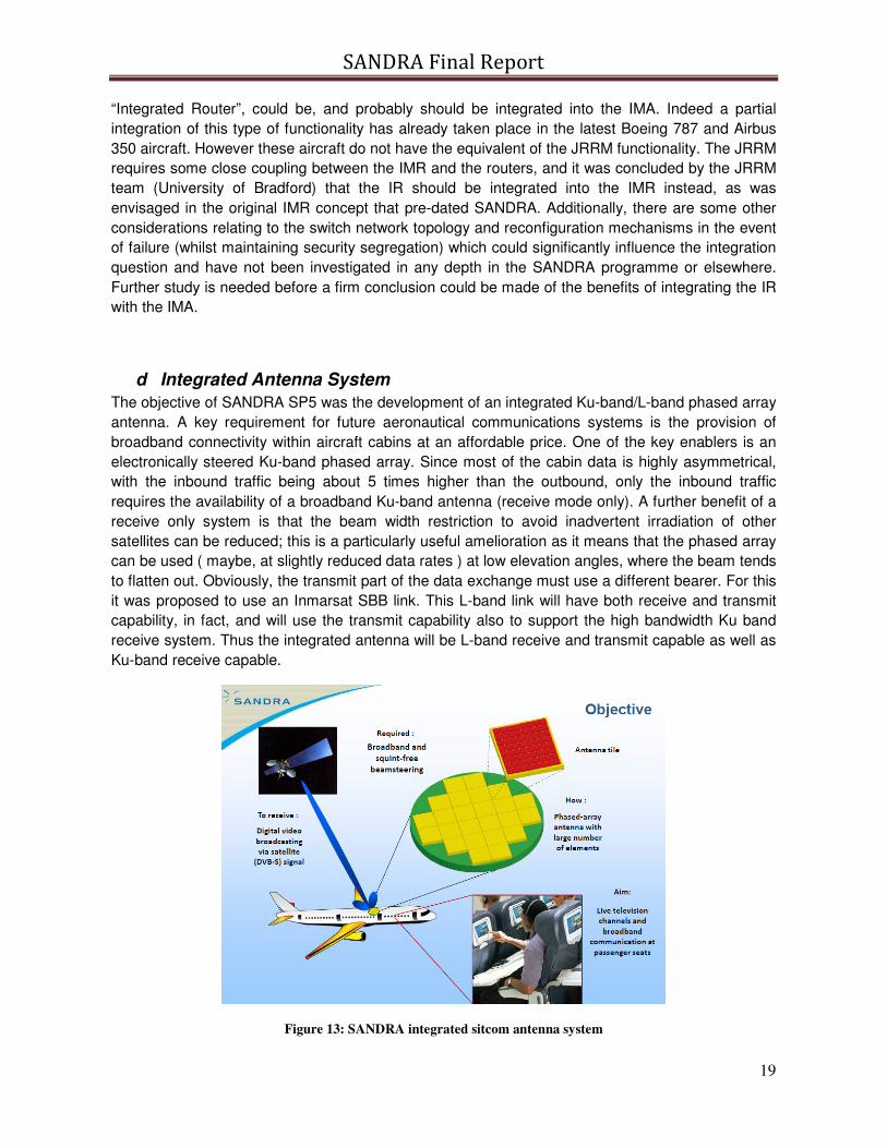
d Integrated Antenna System
The objective of SANDRA SP5 was the development of an integrated Ku-band/L-band phased array
antenna. A key requirement for future aeronautical communications systems is the provision of
broadband connectivity within aircraft cabins at an affordable price. One of the key enablers is an
electronically steered Ku-band phased array. Since most of the cabin data is highly asymmetrical,
with the inbound traffic being about 5 times higher than the outbound, only the inbound traffic
requires the availability of a broadband Ku-band antenna (receive mode only). A further benefit of a
receive only system is that the beam width restriction to avoid inadvertent irradiation of other
satellites can be reduced; this is a particularly useful amelioration as it means that the phased array
can be used ( maybe, at slightly reduced data rates ) at low elevation angles, where the beam tends
to flatten out. Obviously, the transmit part of the data exchange must use a different bearer. For this
it was proposed to use an Inmarsat SBB link. This L-band link will have both receive and transmit
capability, in fact, and will use the transmit capability also to support the high bandwidth Ku band
receive system. Thus the integrated antenna will be L-band receive and transmit capable as well as
Ku-band receive capable.
Figure 13: SANDRA integrated sitcom antenna system
SANDRA Final Report
20
SP5 started with a review of the requirements for L-band and Ku-band SATCOM antennas. These
requirements encompassed System and maintenance requirements, Environmental conditions,
General Electrical requirements, Electromagnetic Compatibility requirements, Certification
requirements, RF requirements and Installation requirements.
Requirements were derived for a final production antenna and for a prototype antenna to be built
during the project. These requirements have been reported in:
• D5.1 Intermediate Requirements Report
• D5.6.2 Final Requirements Report
The main RF requirements were the bandwidth of at least 2 GHz and the beamwidth of 2o. The
requirement for broadband reception was the main driver for the selected beam-forming architecture
with True Time Delays (TTDs).
Figure 14: Ku-band RX only system architecture
Dedicated requirements were derived for the optical beamforming system and the optical
beamforming chip. Optical Ring Resonators (ORR) are used to perform the True Time Delay (TTD)
function. Because of these TTDs, instead of phase shifters, the beamformer has broadband
capabilities. The requirements for the optical beamforming system address the laser, the optical
modulator, the Optical Beamforming Network (OBFN) and the photo-detector. The requirements for
the optical beamforming chip address the ring resonators, combiners, phase shifters and filters
inside the chip. The requirements for the optical beamforming have been reported in:
SANDRA Final Report
21
• D5.4.1.1 OBFS Requirements Report
• D5.4.1.2 OBFC Requirements Report
In D5.4.3 (Architectural design of MMIC sub-array beamforming) a comparison was made between
the classical MMIC beamforming system and a hybrid RF/Optical beamforming system. The hybrid
beamforming system offers a larger bandwidth.
Based on the requirements derived for the prototype antenna, the architecture of the antenna
systems was established. The total Ku-band antenna system consists of an antenna front-end and a
beam forming network. The antenna system is connected to a DVB-S2 receiver. A beam forming
network with tuneable True Time Delays (TTD) is used to guarantee broadband reception (2 GHz
bandwidth). The antenna elements used are stacked patch antennas which also have the required
bandwidth of 2 GHz.
To obtain the required gain of about 37 dB and the beamwidth in the order of 2o, the complete
antenna consists of a phased array antenna with 24 to 32 antenna tiles. Each antenna tile consists
of 8x8 antenna elements. The antenna system uses a hybrid beamforming system in which initial
steering for sub-arrays (2x2 antenna elements) is carried out in the RF domain and the overall
beamforming (16 channels per antenna tile) is performed in the optical domain. The architecture of
the antenna system was reported in
• D5.2 Report for overall architecture of antenna
• D5.6.3 Final report overall architecture
During the first year of the project it was decided that the Ku-band antenna would not be part of the
flight tests at the end of the project. Instead the antenna would be tested in a laboratory
environment (antenna test range). In addition it was decided that a detailed design would be made
for the integrated Ku-band/L-band antenna but that the demonstrator would only consist of a Ku-
band receive antenna because of expected isolation problems.
The future Ku-band antenna system will use a tracking system that will steer the beam of the
antenna to the geostationary satellite, based on the satellite position and the aircraft position and
attitude. Probably two antennas (one on each side of the aircraft fuselage) will be used to be able to
operate the system also at high latitudes (e.g. during transatlantic flights). Earlier studies have
shown that in the case of two antennas, the scan angle of each antenna can be limited to 45
degrees. A study was made of the required tracking system and of the accuracy of the aircraft
position and attitude. The results of this study were reported in:
• D5.4.10 Report on interface between aircraft position/attitude and antenna system
Once the overall architecture was established, then the design of the components of the antenna
system started.
The Ku-band antenna front-end consists of an array of antenna elements with stacked patches. The
patches have been designed to have a good impedance matching over the whole Ku receive band.
In addition the antenna elements were optimised with respect to isolation between the two
polarisations and with respect to isolation between antenna elements (to prevent mutual coupling).
The design of the antenna elements was reported in
• D5.3.1 Report for detailed design of antenna
SANDRA Final Report
22
• D5.3.3 Final report for detailed design of antenna
In the D5.3.3 also the design of the integrated L-band antenna is discussed. Two designs were
presented that could be integrated with the Ku-band antenna. The main problem is the isolation
between L-band and Ku-band. This currently prevents an L-band High Power Amplifier and a Ku-
band Low Noise Amplifier to share the same antenna aperture.
The design of the RF front-end was quite challenging. Because all the RF components and the IF,
LO and DC connectors had to fit within the footprint of an antenna tile, the lay-out of the RF front-
end had become very compact. In addition a high gain had to be realised to amplify the weak signal
of the satellite received by a single antenna element and feed it to the optical modulator. In the RF
front-end a core chip is used for each antenna element. The core chip houses a phase shifter and a
Low Noise Amplifier (LNA). The phase shifter performs the beamforming for the sub-arrays of 2x2
antenna elements. The output of the 4 antenna elements is then combined and fed to an additional
Ku-band amplifier. Subsequently a mixer and image reject filter are used to down-convert the signal
to L-band. Final, an L-band amplifier is used to boost the signal before it is routed to the optical
modulator. The design of the RF front-end has been reported in:
• D5.3.2 Report for design of RF front-end
The architecture of the optical beamforming system was described in
• D5.4.2 Architectural design of optical beamforming network with optical modulators
The architecture describes the optical beamforming system including the laser, the optical
modulator, the Optical Beamforming Network (OBFN) and the photo-detector. Also the architecture
for the ring resonators, combiners, phase shifters and filters inside the OBFN chip is addressed.
Based on the architecture for the optical beamforming system a detailed design of the chip was
made:
• R5.4.5.1 Chip design (Report) and lithographic mask (C)
• Demonstrated possibility of a Federated Radio to interoperate with Integrated Modular Radio
by means of a Proxy
• Demonstrated the possibility to support legacy ATN/OSI applications on new IP based links
(through Mobile IP-SNDCF)
• Demonstrated AeroMACS on a real aircraft within real airport environments
SANDRA prototypes and field trials paved the way to subsequent SESAR P9.16/ P15.2.7 Field
Trials that should conclude, by the end of 2014, the verification of AeroMACS technology, bringing
to the definitive System Profile Validation.
SANDRA also showed that it is possible in the short term to implement a single AeroMACS airborne
terminal to provide services to both Aircraft Control Domain and Airline Information Service Domain.
As a non-exhaustive example, this could be done by taking advantage of some of the SANDRA
results, namely Mobile IP-SNDCF and IPSec traffic segregation.
f Trials and Validation
The validation of the developed SANDRA concept was realized by performing lab and flight trials on
the airport of Oberpfaffenhofen, close to Munich, Germany. This summary gives an overview of the
outcomes of the SANDRA flight trials with a strong emphasis on the seamless handovers that were
carried out between legacy and future data links, namely, VDL2, BGAN, and the newly developed
AeroMACS, thus proving the flexibility and scalability of the SANDRA network. The seamless
service coverage aspect of the SANDRA architecture was demonstrated by the successful test of
various applications in all aeronautical service domains.
SANDRA Final Report
31
The system setup of the SANDRA flight trials is composed of two major segments: the airborne
segment and the ground infrastructure.
The SANDRA airborne system was integrated in an Airbus A320 as displayed in Figure 23.
Figure 23: SANDRA airborne system installed in an A320 including the experimental antennas.
As for the data links, three different radio technologies were integrated in the aircraft: BGAN, VDL2, and AeroMACS. The aircraft was already equipped with a BGAN and a VHF antenna (used to test VDL2), which were located on top, at the rear of the fuselage, and in the middle, below the fuselage, respectively. The AeroMACS C-band antenna was especially mounted on top of the fuselage for the SANDRA flight trials. The inline figures of Figure 2 show the positions of the BGAN, VHF, and AeroMACS antennas on the fuselage of the aircraft.
To be integrated in the aircraft, the SANDRA airborne system was divided into four separate racks containing different pieces of equipment as illustrated in Figure 2. The distribution of equipment within the racks was based on the different functionalities, whereas the locations of the racks within the cabin were defined based on the positions of the antennas on the aircraft’s fuselage.
The racks were organized as follows. The first rack contained the integrated router and the connectivity to the different end-user systems. The second rack was equipped with the two integrated modular radio processing platforms, thus representing the link between the IR and the different RF equipment (one IMR used as redundancy backup). The third rack was fitted with the RF units for the VDL2 and AeroMACS data links. Finally, the RF components that handle the BGAN satellite link were located in the fourth rack at the rear of the cabin. To maximally reduce the antenna cable losses, the third and fourth racks were placed in the cabin right below the respective antennas.
Ground Infrastructure
The core part of the SANDRA ground infrastructure was located at Oberpfaffenhofen, Germany. It is composed of all the IP-based networking components, such as the access router and the home
SANDRA Final Report
32
agent. The home agent includes functionalities like IPsec (IPv6) to provide authentication and integrity and the NEMO protocol to guarantee mobility to the airborne terminal. The IPsec integrates an IPv6-over-IPv4 transition mechanism, entitled NeXT. The access router also provides the router advertisement messages (ICMPv6) required by NEMO on the integrated router. This message is part of the neighbor discovery protocol (NDP, RFC 4861). The SANDRA network provides connectivity not only to the different ground-end systems but also to the ATN, the Internet, and the Public Switched Telephone Network (PSTN, for passenger communication). It enables ATS (communication with air traffic control (ATC)) and AOC services (business communication of the airline) as well as APC (e.g., for Internet access and mobile telephony) and airline nonoperational services (AAC).
For the ground infrastructure of the data links two different base stations were specifically installed for the SANDRA flight trials: a VHF ground station (VGS) and an AeroMACS base station. The latter was installed on top of a hangar building overlooking the Oberpfaffenhofen Airport. Connectivity between this base station and the SANDRA laboratory was established via a VLAN. The antenna used for the AeroMACS base station was a directional antenna (90°) with a focus on the aircraft’s parking position. Furthermore, car tests were carried out at the Oberpfaffenhofen Airport to estimate the received signal level from the AeroMACS base station. A C-band antenna was mounted on the roof of a research vehicle. The signal level could be estimated on the runway, taxiing path, and parking position of the aircraft using a spectrum analyzer.
Finally, for the ATN/OSI ground infrastructure, a VGS for VDL2 was installed on the roof of the SANDRA laboratory close to the airfield, although the ATN/OSI ground-end system was located at Montreal, Canada, and connected to the SANDRA laboratory via a wide area network (WAN). The satellite connection was made over the BGAN satellite network.
Description of Flight Sorties
Six sorties were made in 3 days with the D-ATRA aircraft at a rate of two flights per day (one each in the morning and afternoon). The focus of the first day was mainly to evaluate the correctness of data transmission over the air for each of the three data links. Once the links were operational, the flight trials of the second and third days aimed at validating the SANDRA concept by performing a set of scenarios that were previously identified. To do so, various applications ranging from ATS over AOC, AAC, and APC services were tested onboard the aircraft.
On average, each sortie lasted roughly 90 minutes including taxiing, take-off, and landing phases. The scenarios were performed onboard during the 45 minutes of cruise. For each sortie, the aircraft was flew over the Oberpfaffenhofen Airport and continued its route until the VHF connection was lost. Once out of the VHF coverage, the aircraft turned around to fly back over the Oberpfaffenhofen Airport and thus reentered the VHF coverage. This back-and-forth route over the airport allowed testing the seamless functionality of the SANDRA concept.
Table 2 reveals the different applications that were successfully tested on ground and in the cruising
phase to validate the SANDRA concept. As can be seen in Table 2, applications from all the different
aeronautical service domains were tested during the flight trials, thereby emphasizing the seamless service coverage of SANDRA. As to the airborne end-system, most of the applications were tested using a notebook or tablet directly connected to the integrated router either via an Ethernet cable or via in-cabin wireless local access network. Their counterparts on the ground had various locations, such as the SANDRA laboratory or the different internet servers.
SANDRA Final Report
33
Table 2: List of applications tested during the SANDRA flight trials.
During these flight trials, the two key features of the SANDRA concept were demonstrated. On the one hand, the seamless service coverage of the SANDRA architecture across different airspace domains was shown. By keeping IPv6 as the unification point, it was proven that this system integrates a full range of aeronautical applications (ATS, AOC/AAC, and APC).
The second key feature of the SANDRA concept that was demonstrated during the flight trials was its global interoperability between legacy (VDL2 and BGAN) and future data links (AeroMACS). This was realized by performing, first, a handover on the ground between VDL2 and AeroMACS data links and, second, a handover while flying between the VDL2 and the BGAN satellite links (for both cases, handovers were performed in both directions). Transparent to the end-user, these handovers have proven the interoperable and scalable aspects of the SANDRA network, which can switch reciprocally between legacy (non-IP) and future (IP) data links.
SANDRA Final Report
34
4. Potential Impact & dissemination activities
Potential Impact
Air transport industry faces a complex growth challenge, since airlines are requesting vast increases
in communication capabilities for efficient operations and passenger communications. Moreover, the
equipment and components lifecycles are shortening and the increasing complexity of aeronautical
communication systems is becoming a major concern for airframes.
The SANDRA project will address the integration of currently separated networks in an Airborne
Communication Architecture (ACA) by following a network centric approach and pursuing the
convergence of ATM, AOC, APC communication technologies into one unique architecture. This
system will complement the ATN infrastructure by using Internet Protocols and Integrated Modular
Radio techniques technologies meeting all aeronautical application needs; integration will be
investigated at the service, network, radio and antenna levels.
SANDRA will validate antenna, radio, network and information management technologies that will
contribute to a significant reduction in costs for application development, network configuration,
communication technologies integration. In addition, it will lead to a more efficient and comfortable
aircraft environment for crew and passengers, as well as possibilities to enhance airport and aircraft
logistic efficiency, in line with the goals of ACARE Vision for 2020.
The SANDRA architecture, following the IMA concept, will investigate an architecture that is
significantly cheaper in equipment development, integration and maintenance costs. These features
will greatly improve the market competitiveness of European manufacturers in term of sales
increase and reduction of deployment, installation and maintenance cost.
The European industry today has a strong position in aeronautical and communications domains.
Nevertheless, there is a strong competition from Boeing and from other US avionic companies such
as Rockwell Collins and Honeywell. SANDRA will allow the European companies to reinforce their
competiveness by carrying out research and validating a Network Centric Service Oriented
Architecture for voice and data that will lead to a global system with the potential to satisfy the
increasing request for fast adaptation, easy re-configurability and more customizability by airlines
and airports.
In the first 25 years of the 21st century, European air traffic is expected to approximately double in
volume and it is expected that the current aeronautical ATM communication systems will be
saturated (US forecasts show similar trends). Therefore, to avoid a dramatic service quality
decrease and a general passenger un-satisfaction due to lack of timeliness, the civil aviation has to
count on a sufficient capacity to support this significant growth, whilst maintaining or improving
current safety standards and by reducing costs to sustain international competition. This is the
reason why the EU and the US launched SESAR and NextGen, two parallel massive initiatives with
the respective objectives to propose a new approach to reform the ATM structure in Europe
(SESAR) and to develop a Concept of Operations (CONOPS) for the next generation Air
Transportation system (NextGen) that will operate in the 2020 timeframe and beyond. Such
objectives will be achieved through a combination of new procedures and advances advancements
in the technology deployed to manage passenger, air cargo, general aviation (GA), and air traffic
operations.
SANDRA Final Report
35
SANDRA will fully validate architectures and system technologies able to initiate the transition of
today’s systems into a high performance network centric Service Oriented Architecture to support
the Air Transport transformation, ranging from SESAR developed concepts for Air Traffic
Management to Next Generation IP Networks for passenger communications and in- flight
entertainment and infotainment.
SANDRA will support the high level political and socio-economic expectations of the stakeholder
community, working with and providing SESAR with valuable inputs to support its decision
processes.
In summary, the European Union, its citizens and industries will benefit from the SANDRA project
through the future implementation of the SANDRA technologies and services capabilities, through
improved efficiency, capacity and safety of their Air Transport system, reduced costs and delays
and an enhanced on-board communications service offering.
Dissemination activities
First, the project produced dissemination material in form of a website, logo, to version of project’s
brochure, several press releases and videos. DLR, Selex ES, and Thales UK produced videos for
disseminating the main outcomes of the activities in the field of SP3, SP4, SP6 and SP7. The
footage of the videos is based on DLR material which could be used by all partners for free.
A key activity of SANDRA dissemination is to organise a user forum with a group of operational
experts from “end user” organisations working in the technology fields targeted by SANDRA. These
organizations include aircraft manufacturers, airlines, airports, Air Navigation Service Providers,
suppliers of IT, radio and navigation systems and equipment, international organizations (e.g.
EUROCONTROL, etc.). During the whole project duration, two user forums were organized:
• 29th of September 2011 in Rome, Italy. The results and wrap-up of this forum can be found on the Deliverable D8.4.2.
• 14th of November 2013 in Florence, Italy. The results and wrap-up of this forum can be found on the Deliverable D8.4.4
Overall, both SANDRA User Forums were a success by reaching all identified stakeholders.
In total 11 coordination/cooperation meetings were held with diverse SESAR projects. At the
conclusion of SANDRA project, SESAR and SANDRA Radio and Data Link experts have met in
Florence, hosted by Selex ES, to discuss about the future of aeronautical communications and to
identify opportunities for future cooperation between the SESAR COM project and SANDRA
partners. Several SESAR projects are dealing with communications, investigating at how new Air
Traffic Management requirements for the Single European Sky will be supported and working on
diverse aspects and focusing on Future Mobile data Link system definition (P15.2.4), Future Mobile
Satellite Communication (P15.2.6), New Communication Technology at Airport (P9.16 and P15.2.7)
and Flexible Communication Avionics (P9.44).
SANDRA project has been invited by WiMAX Forum (WMF) to present its AeroMACS activities and
results during the WMF Aviation 2013 event in Washington D.C., USA, 10-11 September 2013. This
first WMF Aviation Event drew more than 100 attendees bringing together the key players of the
Aviation Community and WiMAX ecosystem to discuss opportunities for WiMAX in the Aviation
Community. Attendees were treated to a full two-day program, including speakers from WiMAX
SANDRA Final Report
36
vendors, airlines, airport authorities, various government representatives from the United States,
Europe and Asia, and other groups. Among the speakers also important international figures such
as Nancy Graham, Director of the Air Navigation Bureau, International Civil Aviation Organization
(ICAO), whose remarks made clear to participants the international support for this new market
segment for WiMAX.
During the 9th of June, the already equipped Airbus A320 of DLR was used as a static display during
the Open Day of DLR at their premises in Brunswick, Germany. In overall, around 4000 people were
entering the aircraft having a closer look in to cabin towards the SANDRA equipment. All visitors
were informed about the project by posters and project hand-outs. Figure 24and Figure 25 show the
queues entering the aircraft.
Figure 24: Large interest towards the A320 and the SANDRA project at DLR’s Open Days.
Figure 25: Overview of DLR’s research aircraft at Brunswick during DLR’s Open Days
SANDRA Final Report
37
The SANDRA Project had the great chance of showing their overall flight trial equipment at Paris Air
Show 2013 at Le Bourget. DLR’s research aircraft ATRA was present as a static display.
Furthermore, the Project SANDRA arranges a dedicated SANDRA day, inviting all different
stakeholders to have detailed insight towards the equipment and the project itself. The overall stay
of the aircraft at Le Bourget was a great success. The aircraft was standing in total 5 days at Paris
Air Show accessible for the public. Also the German Federal Minister of Economics and CEO of
DLR were visiting the SANDRA project. Some impressions are given in the following figures.
Figure 26: Impressions of Paris Air Show 2013
In total the SANDRA flight trials were covered by 25 articles on the web in three languages.
The EU Commission announced for Sept-27, 2013 a Researchers Night in different European cities.
The Project SANDRA took the chance to be also present at the Researchers Night in Pisa, Italy. At
the University of Pisa, the project had the possibility to display the main concept and outcomes of
the project. Approximately 500 people were visiting the SANDRA booth during this evening.
SANDRA Final Report
38
Figure 27: SANDRA booth at the European Researchers Night in Pisa, Italy, Sept-27, 2013
The overall dissemination activities were focusing on different target audiences, which could
successfully reached:
• Scientific Community was addressed by various articles published in books, journals and conferences.
• Technical and Industry Community was reached by dedicated meetings and informational events such the User Forum
• The Public was successfully involved due to the possibilities having direct access towards the flight experiment, and therefore, understanding the immediate benefit of these kind of research projects.
Exploitation of results
SANDRA has developed and validated a new aeronautical communication architecture providing
data and digital voice links between the aircraft and ground stations or service providers shared
between the various applicative domains through a fully IP-based network. All links will carry IP
packets, and the avionic radios’ structure and functions will be developed to better handle IP packet-
based communications. In addition the SANDRA radio system is modular and capable of adapt to
all current and future aeronautical radio communications systems due to the definition and use of
standard interfaces and waveforms.
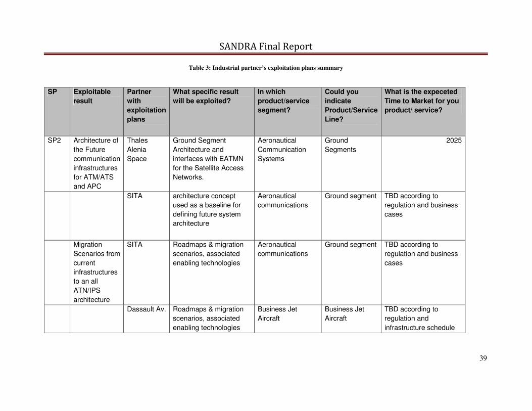
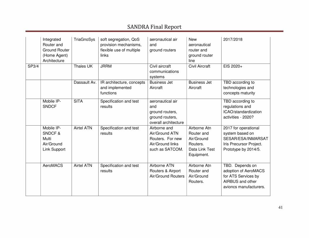
In this section are the industrial products which could be originated, taking into account SANDRA
project exploitable results and end-user trends, as reported D8.2.4 SANDRA Exploitation Plans.
Possible project exploitable results have been identified at an early stage of the project and
classified in terms of TRL and exploitation timeframe, possible results have been monitored during
project execution and then at the end of the project a survey with partners have been conducted in
order to collect their intention to exploit project results into their product/service future offerings.
In the following table the summary of the positive responses from involved partners.


![M. Mascini ERBM4.ppt [Lecture seule]Analytical Signal Molecular Recognition Transduction AFFINITY BIOSENSOR analyte. ... Covalent SELEX/ Chemi SELEX US5763595 1998 US7312325 2001 Toggle](https://static.documents.pub/doc/80x56/611414958f375862326fd980/m-mascini-erbm4ppt-lecture-seule-analytical-signal-molecular-recognition-transduction.jpg)


