Technical Data 1442 Eddy Current Probe Systems Specifications Catalog Numbers 1442-PS series, 1442-PR series, 1442-EC series, 1442-DR series The 1442 series of eddy current probe systems serve applications with measurement ranges from 0.1…29 mm (4…1142 mils). 1442 series probe systems fully satisfy the requirements of API 670 and are suitable for any type of dynamic or static displacement measurement, including vibration, speed/acceleration, rotor/position, and differential expansion measurements. Summary of Changes This manual contains new and updated information. Changes throughout this revision are marked by change bars, as shown to the right of this paragraph. Topic Page Non-contact Pick-up Probe System 2 Wiring Guidelines 3 Match System Components by Color 3 1442 Series Probe System Specifications 4 1442 Series Catalog Numbers 7 Accessories 17 Topic Page Corrected wire sizes 3, 5 Corrected temperature ranges for CSA and ATEX 5 Corrected c-CSA-us and Ex certification information 6
Transcript
Technical Data
1442 Eddy Current Probe Systems SpecificationsCatalog Numbers 1442-PS series, 1442-PR series, 1442-EC series, 1442-DR series
The 1442 series of eddy current probe systems serve applications with measurement ranges from 0.1…29 mm (4…1142 mils). 1442 series probe systems fully satisfy the requirements of API 670 and are suitable for any type of dynamic or static displacement measurement, including vibration, speed/acceleration, rotor/position, and differential expansion measurements.
Summary of Changes
This manual contains new and updated information. Changes throughout this revision are marked by change bars, as shown to the right of this paragraph.
Topic Page
Non-contact Pick-up Probe System 2
Wiring Guidelines 3
Match System Components by Color 3
1442 Series Probe System Specifications 4
1442 Series Catalog Numbers 7
Accessories 17
Topic Page
Corrected wire sizes 3, 5
Corrected temperature ranges for CSA and ATEX 5
Corrected c-CSA-us and Ex certification information 6
1442 Eddy Current Probe Systems Specifications
Non-contact Pick-up Probe System
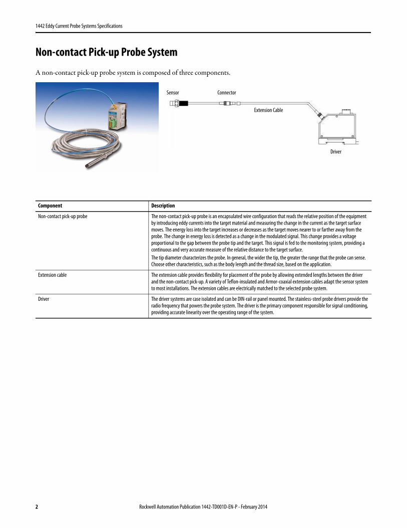
A non-contact pick-up probe system is composed of three components.
Component Description
Non-contact pick-up probe The non-contact pick-up probe is an encapsulated wire configuration that reads the relative position of the equipment by introducing eddy currents into the target material and measuring the change in the current as the target surface moves. The energy loss into the target increases or decreases as the target moves nearer to or farther away from the probe. The change in energy loss is detected as a change in the modulated signal. This change provides a voltage proportional to the gap between the probe tip and the target. This signal is fed to the monitoring system, providing a continuous and very accurate measure of the relative distance to the target surface.The tip diameter characterizes the probe. In general, the wider the tip, the greater the range that the probe can sense. Choose other characteristics, such as the body length and the thread size, based on the application.
Extension cable The extension cable provides flexibility for placement of the probe by allowing extended lengths between the driver and the non-contact pick-up. A variety of Teflon-insulated and Armor-coaxial extension cables adapt the sensor system to most installations. The extension cables are electrically matched to the selected probe system.
Driver The driver systems are case isolated and can be DIN-rail or panel mounted. The stainless-steel probe drivers provide the radio frequency that powers the probe system. The driver is the primary component responsible for signal conditioning, providing accurate linearity over the operating range of the system.
Sensor
Driver
Connector
Extension Cable
2 Rockwell Automation Publication 1442-TD001D-EN-P - February 2014
1442 Eddy Current Probe Systems Specifications
Wiring Guidelines
When wiring the probe driver to a monitor, consider the following recommendations:• Use a good quality instrumentation cable with three-conductor stranded wire and shield. Also consider the
following:– Use wire rated with a maximum capacitance of 60 pF/ft (197 pF/m) and inductance of 0.3 μH/ft (1 μH/m).– Use wire with insulation suitable for the environment and with adequate tensile strength and flexibility for the
application.– Use wire with a foil shield for use in environments where radio frequency interference (RFI) can be present.– Use wire with a braid shield for environments where electromagnetic interference (EMI) can be present.
– Use 0.75…1.25 mm2 (18…16 AWG).• Make sure the wire is isolated from power cables and any other wiring that can be transmitting high voltage power or
control signals.• Isolate any cable transmitting pulse-type vibration signals, such as a phase marker or speed pulse, from displacement
and vibration signals. • Run wire within conduit and cable trays and as per any local electrical codes.• Do not exceed 500 m (1640 ft). However, limiting the length to 300 m (984 ft) guarantees that vibration signals in
the 0…10 kHz frequency range are transmitted with minimal attenuation. When longer lengths are needed, the capacitance of the cable and the desired frequency response of the system must be considered.
• In most cases, make sure that the cable shield is grounded at only one point, generally at the monitor.
Match System Components by Color
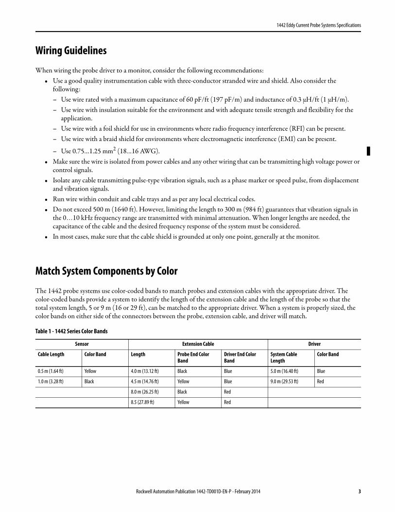
The 1442 probe systems use color-coded bands to match probes and extension cables with the appropriate driver. The color-coded bands provide a system to identify the length of the extension cable and the length of the probe so that the total system length, 5 or 9 m (16 or 29 ft), can be matched to the appropriate driver. When a system is properly sized, the color bands on either side of the connectors between the probe, extension cable, and driver will match.
Table 1 - 1442 Series Color Bands
Sensor Extension Cable Driver
Cable Length Color Band Length Probe End Color Band
Driver End Color Band
System Cable Length
Color Band
0.5 m (1.64 ft) Yellow 4.0 m (13.12 ft) Black Blue 5.0 m (16.40 ft) Blue
1.0 m (3.28 ft) Black 4.5 m (14.76 ft) Yellow Blue 9.0 m (29.53 ft) Red
8.0 m (26.25 ft) Black Red
8.5 (27.89 ft) Yellow Red
Rockwell Automation Publication 1442-TD001D-EN-P - February 2014 3
1442 Eddy Current Probe Systems Specifications
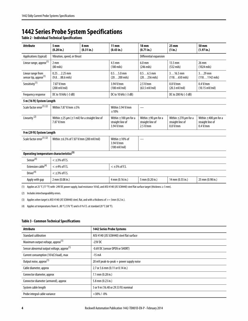
1442 Series Probe System SpecificationsTable 2 - Individual Technical Specifications
Attribute 5 mm(0.20 in.)
8 mm(0.31 in.)
11 mm(0.43 in.)
18 mm(0.71 in.)
25 mm(1 in.)
50 mm(1.97 in.)
Applications (typical) Vibration, speed, or thrust Differential expansion
Linear range, approx(1)
(1) Applies at 25 °C (77 °F) with -24V DC power supply, load resistance 10 kΩ, and AISI 4140 (JIS SCM440) steel flat surface target (thickness ≥ 5 mm).
2 mm(80 mils)
4.5 mm(180 mils)
6.0 mm(246 mils)
13.5 mm(532 mils)
26 mm(1024 mils)
Linear range from sensor tip, approx(1)
0.25…2.25 mm(9.8…88.6 mils)
0.5…5.0 mm(20…200 mils)
0.5…6.5 mm(20…256 mils)
3…16.5 mm(118…650 mils)
3…29 mm(118…1142 mils)
Sensitivity(1) 7.87 V/mm(200 mV/mil)
3.94 V/mm(100 mV/mil)
2.5 V/mm(63.5 mV/mil)
0.8 V/mm(20.3 mV/mil)
0.4 V/mm(10.15 mV/mil)
Frequency response DC to 10 kHz (-3 dB) DC to 10 kHz (-3 dB) DC to 200 Hz (-3 dB)
5 m (16 ft) System Length
Scale factor error(1) (2)
(2) Includes interchangeability errors.
Within 7.87 V/mm ±5% Within 3.94 V/mm ±10%
—
Linearity (2) Within ±25 μm (±1 mil) for a straight line of 7.87 V/mm
Within ±100 μm for a straight line of 3.94 V/mm
Within ±90 μm for a straight line of 2.5 V/mm
Within ±270 μm for a straight line of 0.8 V/mm
Within ±400 μm for a straight line of 0.4 V/mm
9 m (29 ft) System Length
Scale factor error(1) (2) Within ±6.5% of 7.87 V/mm (200 mV/mil) Within ±10% of 3.94 V/mm (100 mV/mil)
—
Operating temperature characteristics(3)
(3) Applies when target is AISI 4140 (JIS SCM440) steel, flat, and with a thickness of >= 5mm (0.2 in.).
Sensor(4)
(4) Applies at temperatures from 0...80 °C (176 °F) and is 0 % F.S. at standard 20 °C (68 °F).
< ±3% of F.S.
Extension cable(4) < ±4% of F.S. < ±3% of F.S.
Driver(4) < ±3% of F.S.
Apply with gap 2 mm (0.08 in.) 4 mm (0.16 in.) 5 mm (0.20 in.) 14 mm (0.55 in.) 25 mm (0.98 in.)
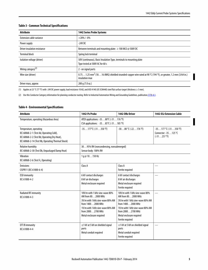
Table 3 - Common Technical Specifications
Attribute 1442 Series Probe Systems
Standard calibration AISI 4140 (JIS SCM440) steel flat surface
Maximum output voltage, approx(1) -23V DC
Sensor abnormal output voltage, approx(1) -0.6V DC (sensor OPEN or SHORT)
Current consumption (10 kΩ load), max -15 mA
Output noise, approx(1) 20 mV peak-to-peak + power supply noise
Cable diameter, approx 2.7 or 3.6 mm (0.11 or 0.14 in.)
Connector diameter, approx 7.1 mm (0.28 in.)
Connector diameter (armored), approx 5.8 mm (0.23 in.)
System cable length 5 or 9 m (16.40 or 29.53 ft) nominal
Probe integral cable variance +30% / -0%
4 Rockwell Automation Publication 1442-TD001D-EN-P - February 2014
1442 Eddy Current Probe Systems Specifications
Extension cable variance +20% / -0%
Power supply -24V DC
Driver insulation resistance Between terminals and mounting plate: ≥ 100 MΩ @ 500V DC
Terminal block Spring lock terminal
Isolation voltage (driver) 50V (continuous), Basic Insulation Type, terminals to mounting plateType tested at 500V AC for 60 s
Wiring category(2) 2 - on signal ports
Wire size (driver) 0.75…1.25 mm2 (18…16 AWG) shielded stranded-copper wire rated at 90 °C (194 °F), or greater, 1.2 mm (3/64 in.) insulation max
Driver mass, approx 200 g (7.0 oz.)
(1) Applies at 25 °C (77 °F) with -24V DC power supply, load resistance 10 kΩ, and AISI 4140 (JIS SCM440) steel flat surface target (thickness ≥ 5 mm).
(2) Use this Conductor Category information for planning conductor routing. Refer to Industrial Automation Wiring and Grounding Guidelines, publication 1770-4.1.
6 kV contact discharges8 kV air dischargesMetal enclosure required
6 kV contact discharges8 kV air dischargesMetal enclosure requiredFerrite required
—
Radiated RF immunityIEC 61000-4-3
10V/m with 1 kHz sine-wave 80% AM from 80…2000 MHz3V/m with 1 kHz sine-wave 80% AM from 1400…2000 MHz1V/m with 1 kHz sine-wave 80% AM from 2000…2700 MHzMetal enclosure required
10V/m with 1 kHz sine-wave 80% AM from 80…2000 MHz3V/m with 1 kHz sine-wave 80% AM from 1400…2000 MHz1V/m with 1 kHz sine-wave 80% AM from 2000…2700 MHzMetal enclosure requiredFerrite required
—
EFT/B immunityIEC 61000-4-4
±1 kV at 5 kH on shielded signal portsMetal conduit required
±1 kV at 5 kH on shielded signal portsMetal conduit requiredFerrite required
—
Table 3 - Common Technical Specifications
Attribute 1442 Series Probe Systems
Rockwell Automation Publication 1442-TD001D-EN-P - February 2014 5
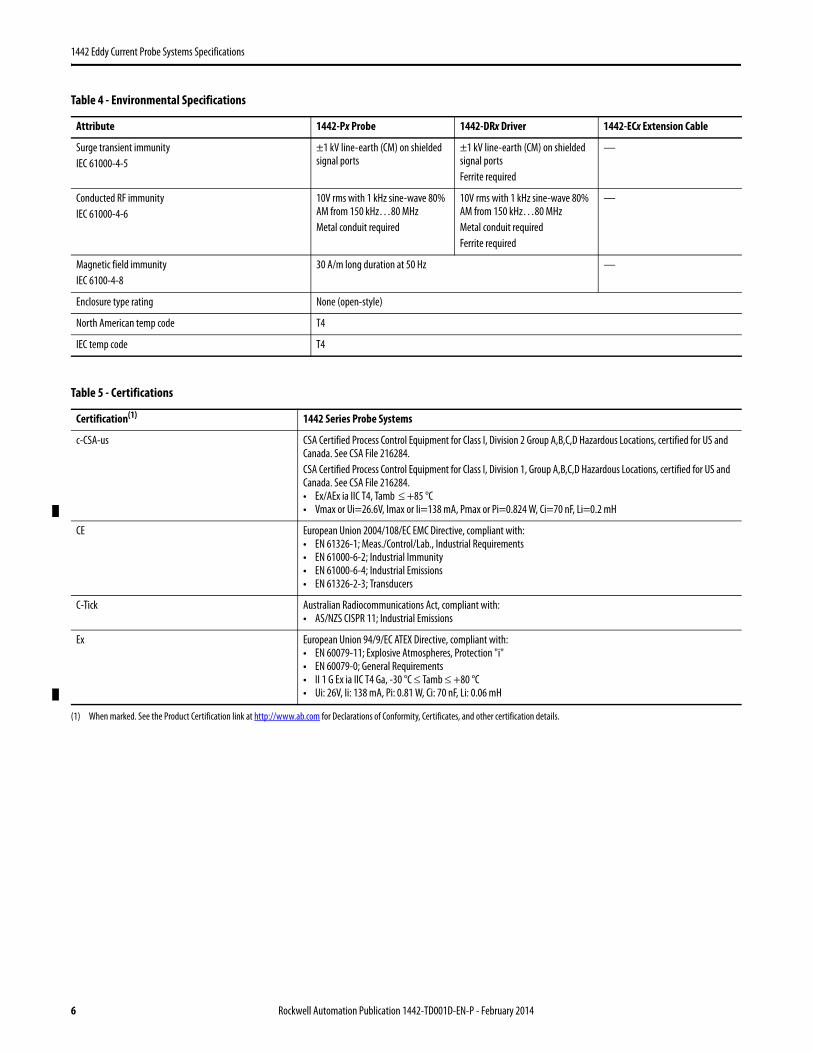
±1 kV line-earth (CM) on shielded signal portsFerrite required
—
Conducted RF immunityIEC 61000-4-6
10V rms with 1 kHz sine-wave 80% AM from 150 kHz…80 MHzMetal conduit required
10V rms with 1 kHz sine-wave 80% AM from 150 kHz…80 MHzMetal conduit requiredFerrite required
—
Magnetic field immunityIEC 6100-4-8
30 A/m long duration at 50 Hz —
Enclosure type rating None (open-style)
North American temp code T4
IEC temp code T4
Table 5 - Certifications
Certification(1)
(1) When marked. See the Product Certification link at http://www.ab.com for Declarations of Conformity, Certificates, and other certification details.
1442 Series Probe Systems
c-CSA-us CSA Certified Process Control Equipment for Class I, Division 2 Group A,B,C,D Hazardous Locations, certified for US and Canada. See CSA File 216284.CSA Certified Process Control Equipment for Class I, Division 1, Group A,B,C,D Hazardous Locations, certified for US and Canada. See CSA File 216284.• Ex/AEx ia IIC T4, Tamb ≤ +85 °C• Vmax or Ui=26.6V, Imax or Ii=138 mA, Pmax or Pi=0.824 W, Ci=70 nF, Li=0.2 mH
CE European Union 2004/108/EC EMC Directive, compliant with:• EN 61326-1; Meas./Control/Lab., Industrial Requirements• EN 61000-6-2; Industrial Immunity• EN 61000-6-4; Industrial Emissions• EN 61326-2-3; Transducers
Ex European Union 94/9/EC ATEX Directive, compliant with:• EN 60079-11; Explosive Atmospheres, Protection "i"• EN 60079-0; General Requirements• II 1 G Ex ia IIC T4 Ga, -30 °C ≤ Tamb ≤ +80 °C • Ui: 26V, Ii: 138 mA, Pi: 0.81 W, Ci: 70 nF, Li: 0.06 mH
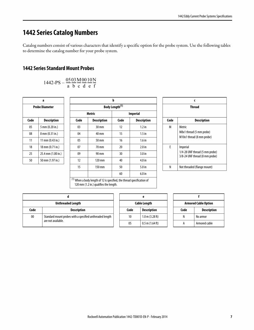
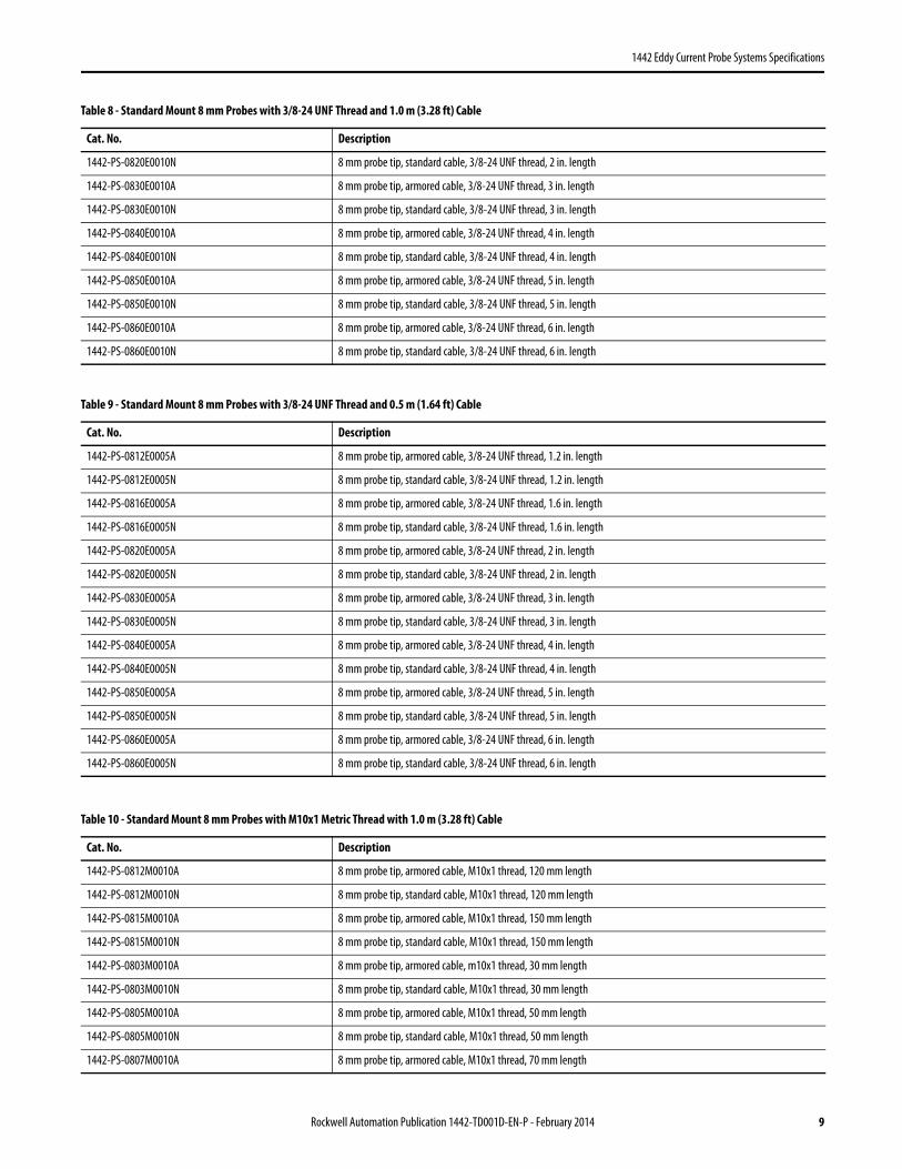
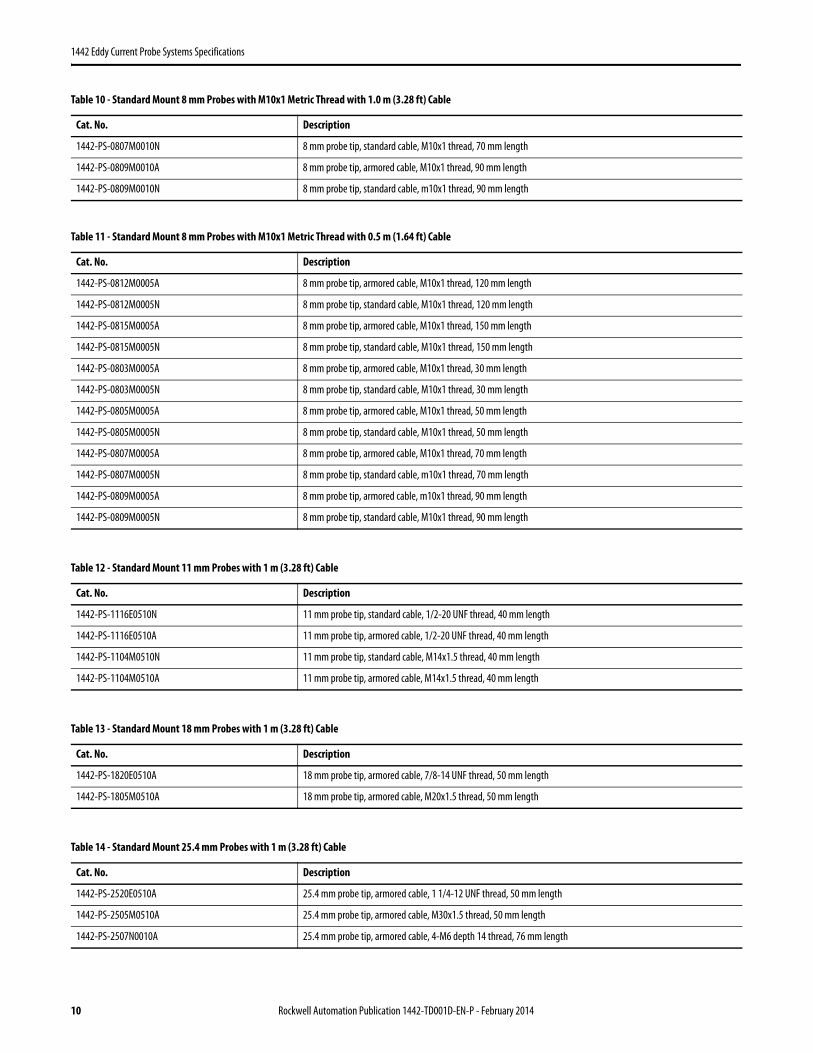
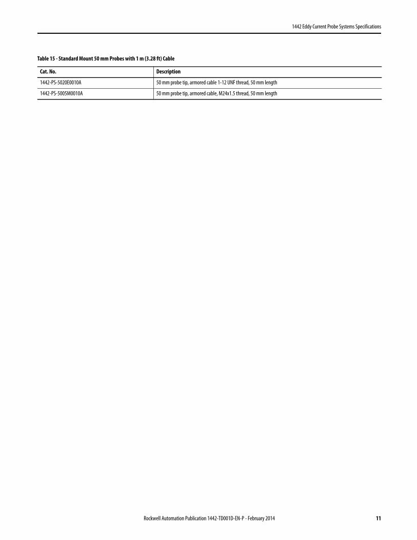
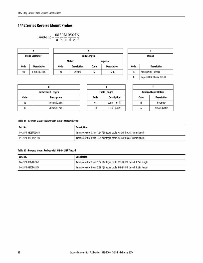
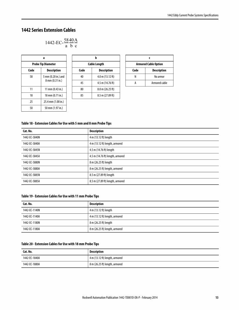
Catalog numbers consist of various characters that identify a specific option for the probe system. Use the following tables to determine the catalog number for your probe system.
Table 18 - Extension Cables for Use with 5 mm and 8 mm Probe Tips
Cat. No. Description
1442-EC-5840N 4 m (13.12 ft) length
1442-EC-5840A 4 m (13.12 ft) length, armored
1442-EC-5845N 4.5 m (14.76 ft) length
1442-EC-5845A 4.5 m (14.76 ft) length, armored
1442-EC-5880N 8 m (26.25 ft) length
1442-EC-5880A 8 m (26.25 ft) length, armored
1442-EC-5885N 8.5 m (27.89 ft) length
1442-EC-5885A 8.5 m (27.89 ft) length, armored
Table 19 - Extension Cables for Use with 11 mm Probe Tips
Cat. No. Description
1442-EC-1140N 4 m (13.12 ft) length
1442-EC-1140A 4 m (13.12 ft) length, armored
1442-EC-1180N 8 m (26.25 ft) length
1442-EC-1180A 8 m (26.25 ft) length, armored
Table 20 - Extension Cables for Use with 18 mm Probe Tips
Cat. No. Description
1442-EC-1840A 4 m (13.12 ft) length, armored
1442-EC-1880A 8 m (26.25 ft) length, armored
1442-EC-58
a------
40
b------
A
c----
Rockwell Automation Publication 1442-TD001D-EN-P - February 2014 13
1442 Eddy Current Probe Systems Specifications
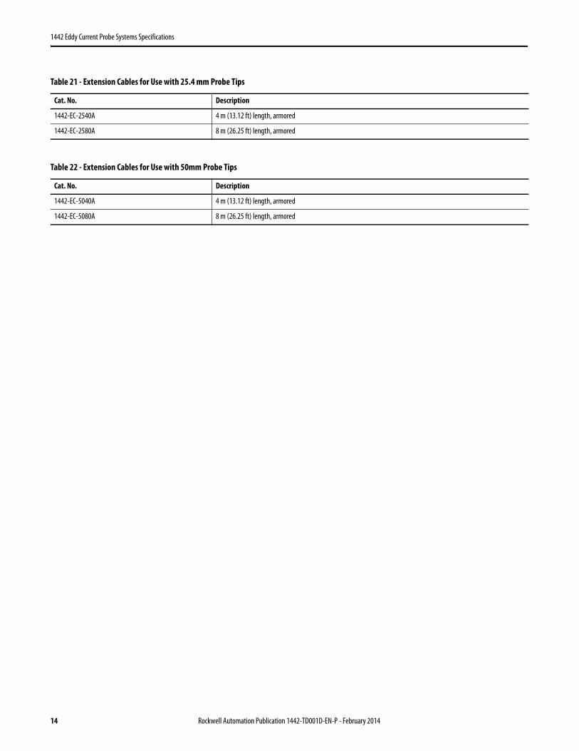
Table 21 - Extension Cables for Use with 25.4 mm Probe Tips
Cat. No. Description
1442-EC-2540A 4 m (13.12 ft) length, armored
1442-EC-2580A 8 m (26.25 ft) length, armored
Table 22 - Extension Cables for Use with 50mm Probe Tips
Cat. No. Description
1442-EC-5040A 4 m (13.12 ft) length, armored
1442-EC-5080A 8 m (26.25 ft) length, armored
14 Rockwell Automation Publication 1442-TD001D-EN-P - February 2014
1442 Eddy Current Probe Systems Specifications
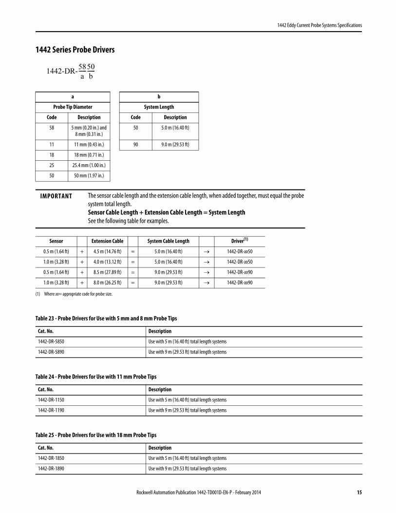
1442 Series Probe Drivers
a b
Probe Tip Diameter System Length
Code Description Code Description
58 5 mm (0.20 in.) and 8 mm (0.31 in.)
50 5.0 m (16.40 ft)
11 11 mm (0.43 in.) 90 9.0 m (29.53 ft)
18 18 mm (0.71 in.)
25 25.4 mm (1.00 in.)
50 50 mm (1.97 in.)
IMPORTANT The sensor cable length and the extension cable length, when added together, must equal the probe system total length. Sensor Cable Length + Extension Cable Length = System LengthSee the following table for examples.
Sensor Extension Cable System Cable Length Driver(1)
(1) Where xx= appropriate code for probe size.
0.5 m (1.64 ft) + 4.5 m (14.76 ft) = 5.0 m (16.40 ft) → 1442-DR-xx50
1.0 m (3.28 ft) + 4.0 m (13.12 ft) = 5.0 m (16.40 ft) → 1442-DR-xx50
0.5 m (1.64 ft) + 8.5 m (27.89 ft) = 9.0 m (29.53 ft) → 1442-DR-xx90
1.0 m (3.28 ft) + 8.0 m (26.25 ft) = 9.0 m (29.53 ft) → 1442-DR-xx90
Table 23 - Probe Drivers for Use with 5 mm and 8 mm Probe Tips
Cat. No. Description
1442-DR-5850 Use with 5 m (16.40 ft) total length systems
1442-DR-5890 Use with 9 m (29.53 ft) total length systems
Table 24 - Probe Drivers for Use with 11 mm Probe Tips
Cat. No. Description
1442-DR-1150 Use with 5 m (16.40 ft) total length systems
1442-DR-1190 Use with 9 m (29.53 ft) total length systems
Table 25 - Probe Drivers for Use with 18 mm Probe Tips
Cat. No. Description
1442-DR-1850 Use with 5 m (16.40 ft) total length systems
1442-DR-1890 Use with 9 m (29.53 ft) total length systems
1442-DR-58
a------
50
b------
Rockwell Automation Publication 1442-TD001D-EN-P - February 2014 15
1442 Eddy Current Probe Systems Specifications
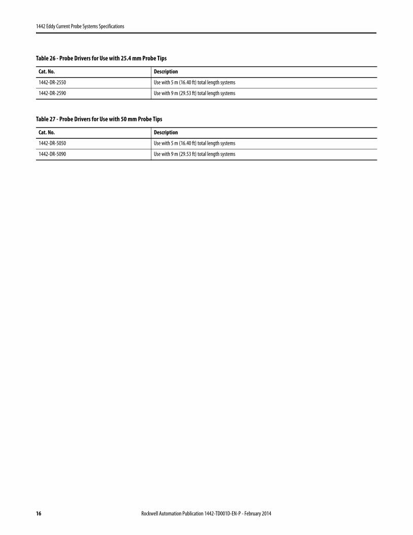
Table 26 - Probe Drivers for Use with 25.4 mm Probe Tips
Cat. No. Description
1442-DR-2550 Use with 5 m (16.40 ft) total length systems
1442-DR-2590 Use with 9 m (29.53 ft) total length systems
Table 27 - Probe Drivers for Use with 50 mm Probe Tips
Cat. No. Description
1442-DR-5050 Use with 5 m (16.40 ft) total length systems
1442-DR-5090 Use with 9 m (29.53 ft) total length systems
16 Rockwell Automation Publication 1442-TD001D-EN-P - February 2014
1442 Eddy Current Probe Systems Specifications
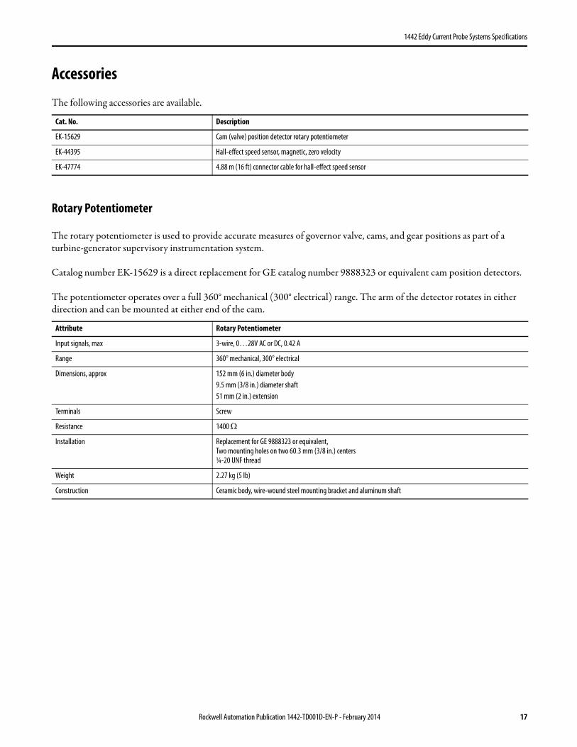
Accessories
The following accessories are available.
Rotary Potentiometer
The rotary potentiometer is used to provide accurate measures of governor valve, cams, and gear positions as part of a turbine-generator supervisory instrumentation system.
Catalog number EK-15629 is a direct replacement for GE catalog number 9888323 or equivalent cam position detectors.
The potentiometer operates over a full 360° mechanical (300° electrical) range. The arm of the detector rotates in either direction and can be mounted at either end of the cam.
Cat. No. Description
EK-15629 Cam (valve) position detector rotary potentiometer
EK-44395 Hall-effect speed sensor, magnetic, zero velocity
EK-47774 4.88 m (16 ft) connector cable for hall-effect speed sensor
Attribute Rotary Potentiometer
Input signals, max 3-wire, 0…28V AC or DC, 0.42 A
Range 360° mechanical, 300° electrical
Dimensions, approx 152 mm (6 in.) diameter body9.5 mm (3/8 in.) diameter shaft 51 mm (2 in.) extension
Terminals Screw
Resistance 1400 Ω
Installation Replacement for GE 9888323 or equivalent,Two mounting holes on two 60.3 mm (3/8 in.) centers¼-20 UNF thread
Weight 2.27 kg (5 lb)
Construction Ceramic body, wire-wound steel mounting bracket and aluminum shaft
Rockwell Automation Publication 1442-TD001D-EN-P - February 2014 17
1442 Eddy Current Probe Systems Specifications
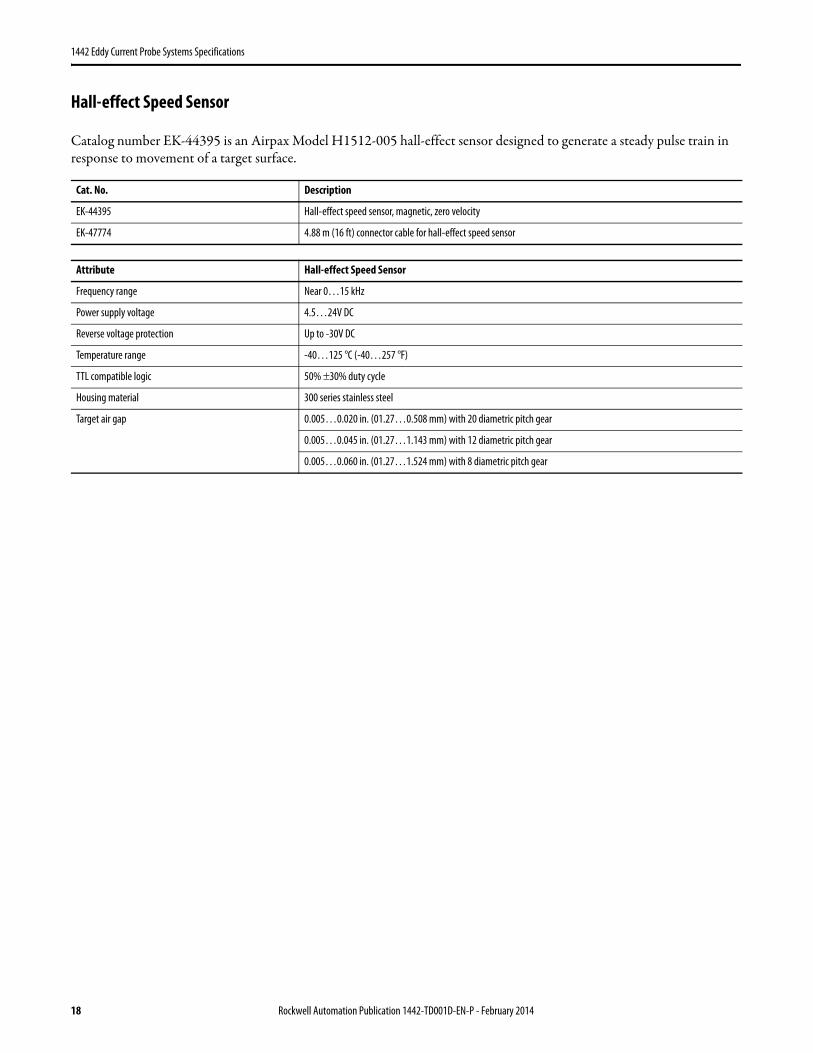
Hall-effect Speed Sensor
Catalog number EK-44395 is an Airpax Model H1512-005 hall-effect sensor designed to generate a steady pulse train in response to movement of a target surface.
Cat. No. Description
EK-44395 Hall-effect speed sensor, magnetic, zero velocity
EK-47774 4.88 m (16 ft) connector cable for hall-effect speed sensor
Attribute Hall-effect Speed Sensor
Frequency range Near 0…15 kHz
Power supply voltage 4.5…24V DC
Reverse voltage protection Up to -30V DC
Temperature range -40…125 °C (-40…257 °F)
TTL compatible logic 50% ±30% duty cycle
Housing material 300 series stainless steel
Target air gap 0.005…0.020 in. (01.27…0.508 mm) with 20 diametric pitch gear
0.005…0.045 in. (01.27…1.143 mm) with 12 diametric pitch gear
0.005…0.060 in. (01.27…1.524 mm) with 8 diametric pitch gear
18 Rockwell Automation Publication 1442-TD001D-EN-P - February 2014
1442 Eddy Current Probe Systems Specifications
Notes:
Rockwell Automation Publication 1442-TD001D-EN-P - February 2014 19
Allen-Bradley, Rockwell Software, Rockwell Automation, and LISTEN. THINK. SOLVE are trademarks of Rockwell Automation, Inc.
Trademarks not belonging to Rockwell Automation are property of their respective companies.
Solid-state equipment has operational characteristics differing from those of electromechanical equipment. Safety Guidelines for the Application, Installation and Maintenance of Solid State Controls (publication SGI-1.1 available from your local Rockwell Automation sales office or online at http://www.rockwellautomation.com/literature/) describes some important differences between solid-state equipment and hard-wired electromechanical devices. Because of this difference, and also because of the wide variety of uses for solid-state equipment, all persons responsible for applying this equipment must satisfy themselves that each intended application of this equipment is acceptable.
In no event will Rockwell Automation, Inc. be responsible or liable for indirect or consequential damages resulting from the use or application of this equipment.
The examples and diagrams in this publication are included solely for illustrative purposes. Because of the many variables and requirements associated with any particular installation, Rockwell Automation, Inc. cannot assume responsibility or liability for actual use based on the examples and diagrams.
No patent liability is assumed by Rockwell Automation, Inc. with respect to use of information, circuits, equipment, or software described in this manual.
Reproduction of the contents of this manual, in whole or in part, without written permission of Rockwell Automation, Inc., is prohibited.
Documentation Feedback
Your comments will help us serve your documentation needs better. If you have any suggestions on how to improve this document, complete this form, publication RA-DU002, available at http://www.rockwellautomation.com/literature/.
Rockwell Otomasyon Ticaret A.Ş., Kar Plaza İş Merkezi E Blok Kat:6 34752 İçerenköy, İstanbul, Tel: +90 (216) 5698400