Revised 1/2013 14.532 THEORETICAL SOIL MECHANICS Stresses in a Soil Mass Slide 1 of 23 VERTICAL STRESS INCREASES IN SOILS TYPES OF LOADING Point Loads (P) Figure 6.11. Das FGE (2005). Examples: - Railroad track Examples: - Posts Line Loads (q/unit length) Figure 6.12. Das FGE (2005).
Transcript
Revised 1/2013
14.532 THEORETICAL SOIL MECHANICSStresses in a Soil Mass
Slide 1 of 23
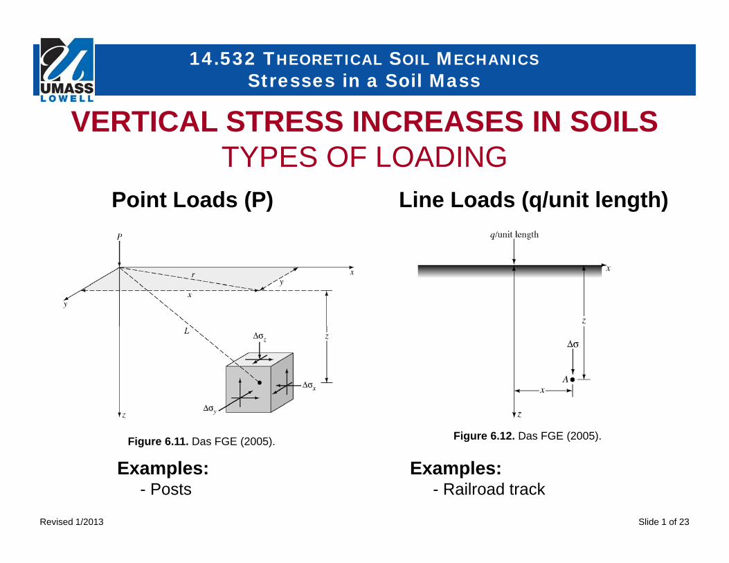
VERTICAL STRESS INCREASES IN SOILSTYPES OF LOADING
Point Loads (P)
Figure 6.11. Das FGE (2005).
Examples:- Railroad track
Examples:- Posts
Line Loads (q/unit length)
Figure 6.12. Das FGE (2005).
Revised 1/2013
14.532 THEORETICAL SOIL MECHANICSStresses in a Soil Mass
Slide 2 of 23
Examples:- Exterior Wall Foundations
Examples:- Column Footings
VERTICAL STRESS INCREASES IN SOILSTYPES OF LOADING
Area Loads (q)Strip Loads (q)
Revised 1/2013
14.532 THEORETICAL SOIL MECHANICSStresses in a Soil Mass
Slide 3 of 23
VERTICAL STRESS INCREASE IN SOILSANALYSIS METHODS - BOUSSINESQ (1883)Based on homogeneous, weightless, elastic, isotropic infinitely large half-space free of initial stress and deformation. The modulus of elasticity is assumed constant and the principle of linear superposition is assumed valid (EM1110-1-1904, 1990). Not accurate for layered soil stratigraphy with substantial thickness (NAVFAC DM7.01, 1986).
Rigid Surface Layer Over Weaker Underlying Layer: If the surface layer is the more rigid, it acts as a distributing mat and the vertical stresses in the underlying soil layer are less than Boussinesq values.
Weaker Surface Layer Over Stronger Underlying Layers: If the surface layer is less rigid than the underlying layer, then vertical stresses in both layers exceed the Boussinesq values.
Revised 1/2013
14.532 THEORETICAL SOIL MECHANICSStresses in a Soil Mass
Slide 4 of 23
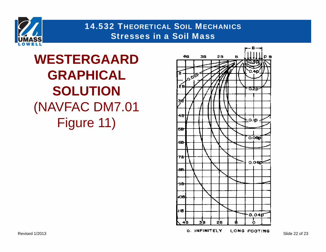
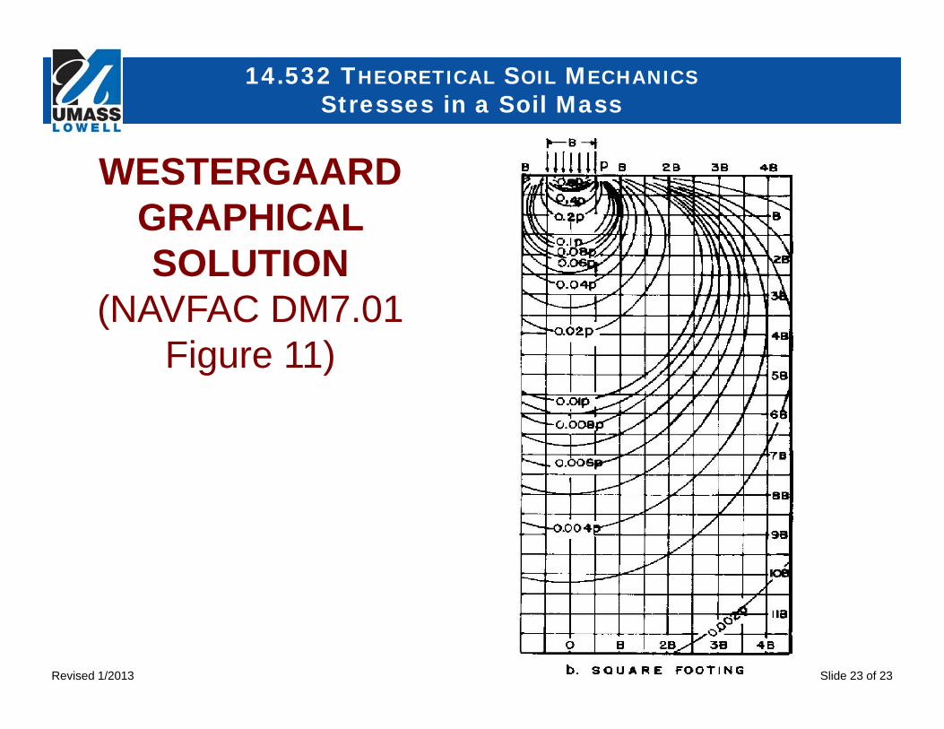
VERTICAL STRESS INCREASE IN SOILSANALYSIS METHODS - WESTERGAARD
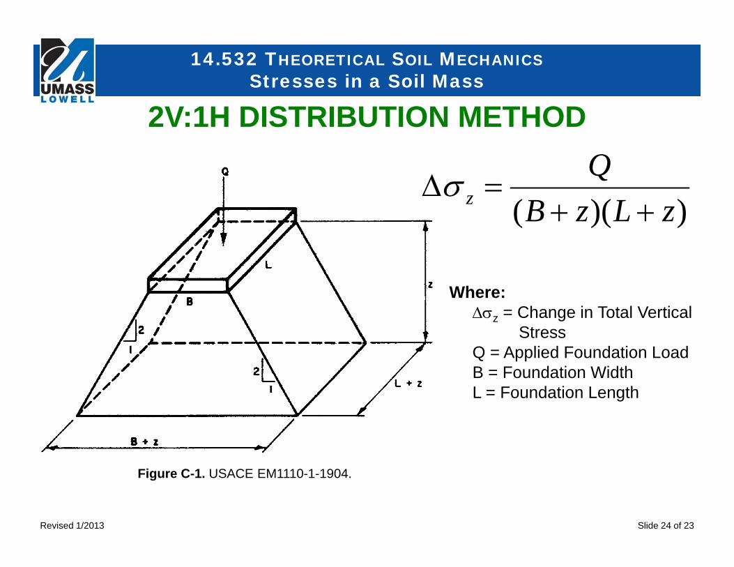
VERTICAL STRESS INCREASE IN SOILSANALYSIS METHODS – 2V:1H METHOD
Based on the assumption that the soil on which load is applied is reinforcedby closely spaced horizontal layers which prevent horizontal displacement.The effect of the Westergaard assumption is to reduce the stressessubstantially below those obtained by the Boussinesq equations.
An approximate stress distribution assumes that the total applied load onthe surface of the soil is distributed over an area of the same shape as theloaded area on the surface, but with dimensions that increase by anamount equal to the depth below the surface.Vertical stresses calculated 2V:1H method agree reasonably well withthe Boussinesq method for depths between B and 4B below thefoundation.
Revised 1/2013
14.532 THEORETICAL SOIL MECHANICSStresses in a Soil Mass
Slide 5 of 23
2/522
3
5
3
)(23
23
zrzP
LzP
z
122/5221/
123 I
zP
zrzP
z
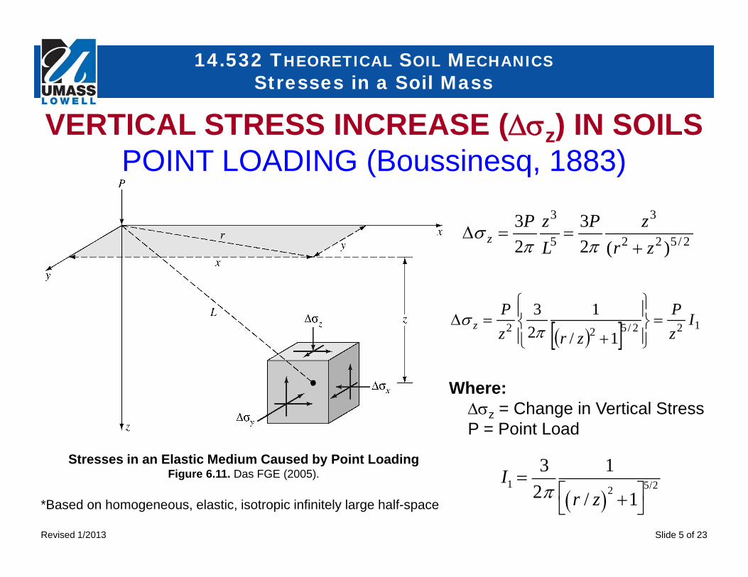
VERTICAL STRESS INCREASE (z) IN SOILSPOINT LOADING (Boussinesq, 1883)
Stresses in an Elastic Medium Caused by Point LoadingFigure 6.11. Das FGE (2005).
Where:z = Change in Vertical StressP = Point Load
I1 3
21
r / z 2 1
5/2
*Based on homogeneous, elastic, isotropic infinitely large half-space
Revised 1/2013
14.532 THEORETICAL SOIL MECHANICSStresses in a Soil Mass
Slide 6 of 23
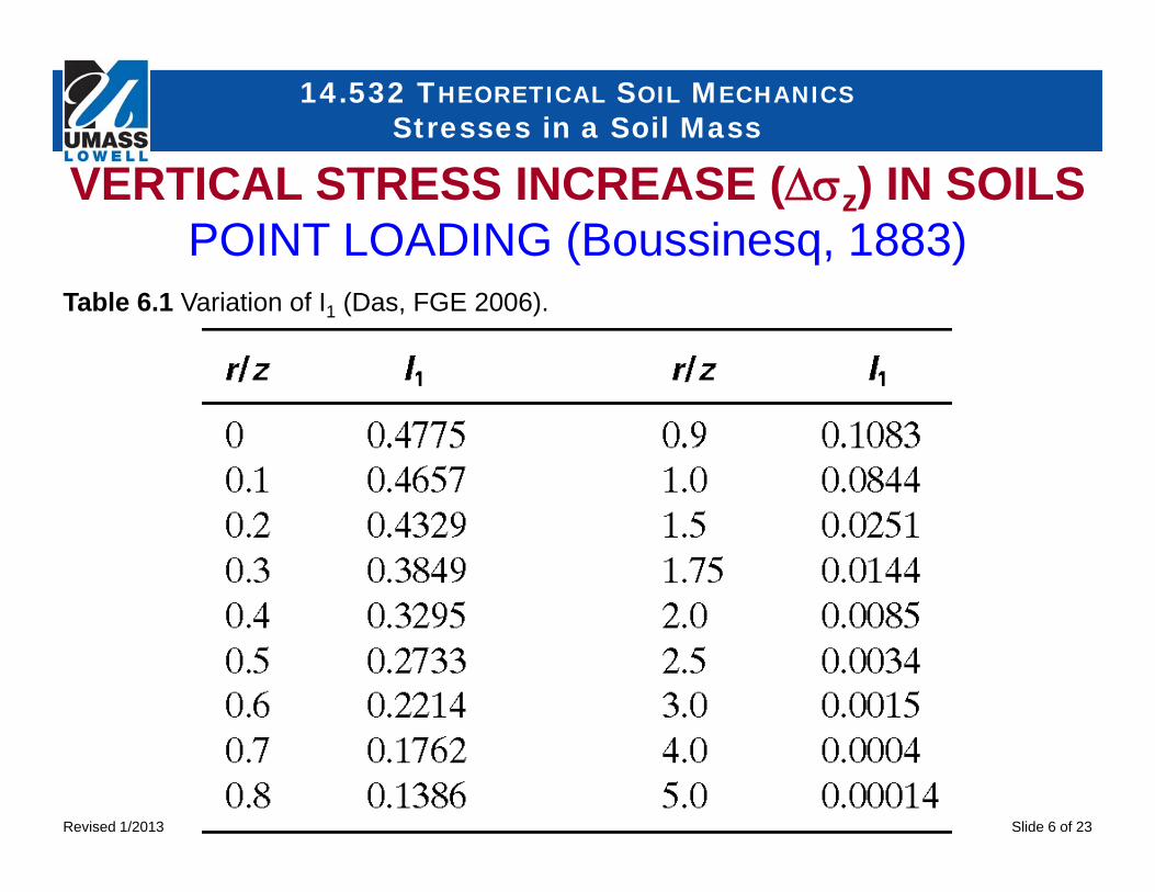
Table 6.1 Variation of I1 (Das, FGE 2006).
VERTICAL STRESS INCREASE (z) IN SOILSPOINT LOADING (Boussinesq, 1883)
Revised 1/2013
14.532 THEORETICAL SOIL MECHANICSStresses in a Soil Mass
Slide 7 of 23
22
222
3
1
2)/(
)(2
zxzq
zxqz
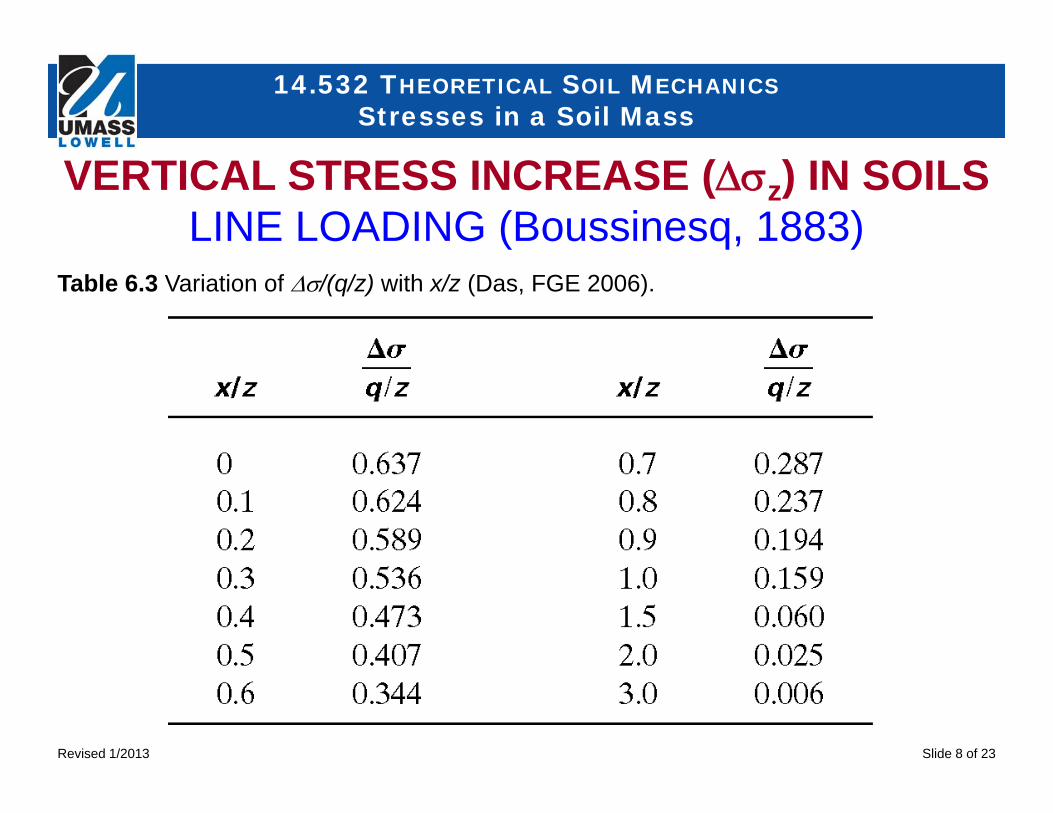
Where: = Change in Vertical Stressq = Load per Unit Lengthz = Depthx = Distance from Line Load *Based on flexible line load of infinite length on a