12
CDA InterCorp EDDY CURRENT DAMPER APPLICATION DATA

CCDDAA IInntteerrCCoorrpp
EDDY CURRENT DAMPERAPPLICATION DATA

This application manual defines the performance capabilities of CDA InterCorp’s Eddy CurrentDamper Product line, in-line and right angle gearing, and linear damper interface options.
The design data contained herein reflects the continuous demand for improved performance, effi-ciency, and reliability, while simplifying drive techniques, and minimizing size and weight. CDAInterCorp’s eddy current dampers are designed to operate under the most demanding requirementsof MIL-STD--810, while maintaining robust, reliable damping characteristics. These dampers, andsimilar products are used in aerospace, outer space, defense, commercial aviation, “down hole”,robotic, nuclear, and high reliability industrial control applications.
With 30 years in the industry, CDA InterCorp’s core philosophy of modular standardization has with-stood the test of time. Each module design utilizes the same inventoried piece part standards, mate-rials, processes, and construction techniques. Inherent in our standard modules are unequaled reli-ability and ruggedness, while maintaining flexibility in providing custom damper requirements andextremely responsive prototype and production deliveries.
CDA maintains a quality inspection system which provides traceability, product assurance, and per-formance. A government quality representative is available to provide source inspection, as required.
For responsive support for your specific requirements , please write, phone, fax, or e-mail CDAInterCorp directly. CDA’s system application engineers are available to visit your facility to assist inthe design and selection of the proper Eddy Current Damper Assembly for your specific application.
CC DD AA II nn tt ee rr CC oo rr ppII NN TT RR OO DD UU CC TT II OO NN

TABLE OF CONTENTS
Eddy Current Dampers.....................................................................................................2
ECD Mechanical Data........................................................................................................3
Damper - Gearhead Composite Dimensions and Performance - Imperial Units.......................4
Damper - Gearhead Composite Dimensions and Performance - SI Units.......................5
Gearhead Performance Ratings.................................................................................................5
Damper / Right Angle Gearhead Composite Dimensions and Performance - Imperial Units....6
Damper / Right Angle Gearhead Composite Dimensions and Performance - SI Units........7
Right Angle Gearhead Performance Ratings....................................................................7
ECD Nomenclature and Damper Equations..........................................................................8
Application Information Fax Data Sheet..................................................................9
1

CDA InterCorp’s Rotary and Linear Eddy Current Dampers offerreliable, repeatable, and linear damping characteristics over awide operating temperature range. These rugged devices areoffered in a range of sizes and damping rates. The EddyCurrent Dampers (ECD’s) are complemented with single or mul-tiple stages of high reliability gearing. Ideal for demandingapplications, these devices will operate reliably at high angularrates, accelerations and radial loads.
CDA InterCorp’s seven standard frame size ECD’s and our com-plementary line of gearboxes offer nearly unlimited dampingrates, configurations, and torque capacities. Our compact andefficient gearboxes are so robust and compact, that we oftenrival the size and mass of fluid dampers for equivalent dampingrates and torques; however, our ECD’s are much more reliableand temperature stable than fluid dampers. ECD’s are extreme-ly linear and have low temperature coefficients, where thedamping rates and performance are very stable over operatingtemperature ranges. Our ECD damping rates are so linear andpredictable, that temperature compensation is usually notrequired. Where fluid dampers usually suffer from “dead band”with up to ten or more degrees of lost motion, our geared ECD’shave only a few arc-minutes of lost motion, providing a morerobust, controlled deployment. Our ECD’s do not require, andare not dependent on seals. The elimination of seals, and nopotential for leaks gives ECD’s a clear advantage in performanceor outgassing critical applications. Also, the ECD’s performancedoes not change inside a vacuum. The increased reliability andperformance of our ECD’s typically save many hours of assem-bly and integration time.
Our efforts to develop a low static friction, high reliability ECDhas proven successful. We can now offer low static friction val-ues without compromising capacity or reliability. Our currentline of ECD’s have reduced static friction by 75% for a givenframe size and damping rate. Often our geared ECD’s canform fit function replace fluid dampers in deployment actuationsystems with the high reliability and temperature stability inher-ent in our ECD modules.
Linear Stroke Dampers: CDA InterCorp may also provideLinear Eddy Current Dampers (LECD’s) by incorporating a highefficiency ball screw to the output of our rotary dampers. TheseLECD’s may incorporate various mounting configurations forflexible system integration. For Linear ECD analysis, refer toCDA InterCorp’s Product Summary brochure for rotary to lineartranslation equations, and linear mounting interface options.
Damping on Command: CDA InterCorp may provide ourECD’s with a damping enable feature which allows the damp-ing restrictive torque to be turned off and on at will. This mayoffer advantages to the system or mechanism design by allow-ing the flexibility to command the damping. Contact CDA’sengineering department for further information aboutDamping on Command.
System Level Calibration can also be reliably achieved onour ECD’s. Unlike fluid dampers which have a screw provisionwhich may vibrate loose and change position during launch,CDA InterCorp’s ECD’s can be system level calibrated by addinga proper load resistor across external leads. CDA can provide amatrix of load resistors vs. damping rate at the output of a
given ECD.
The damping rates, maximum torques, radial loads, and peakvelocities are determining factors in selecting the proper ECD orLECD. This Application Data summary is formatted to assist inthe design and selection of an ECD for a specific application.
HIGH TORQUE CAPACITY GEARING
As with our standard damper frame sizes, CDA InterCorp inven-tories the fundamental gear blanks and piece parts for our lineof high torque gearboxes. These durable devices are manufac-tured with the same high precision tolerances as our dampermodules. The critical interface between the high speed ECDshaft and the high efficiency gearbox is held to very tight toler-ances. This assures high reliability performance at high veloci-ties, maximizing efficiency, and minimizing weight, while main-taining linearity.
As with the damper modules, our gearing consists of highgrade stainless steel construction with matched coefficient ofthermal expansion. Our standard geared actuators have oper-ated from 4 Kelvin (-269˚ C) to +250˚ C. High torsional andradial stiffness with low backlash are also inherent in our stan-dard gear modules making them ideal for high torque deploy-ment mechanisms.
For length critical applications, CDA InterCorp has an entire lineof right angle gearboxes to complement each frame size of ourplanetary gearboxes. Our placement of the critical right angleconversion is at the optimum ratio of torque and velocity whichresults in a gearbox which has the identical torque, stiffness,and backlash ratings as the comparable in line planetary gear-box. See pages 6 and 7 for our right angle drive damper per-formance and composite dimensions.
Extensive field heritage and continuous endurance testing pro-vides for a large data base of performance and reliability for ourgeared packages. Most of our applications are mission critical,and some are even flight safety critical. We are able to accom-modate all these demanding applications with our standardmodular design concept. Another advantage derived from thisconcept is responsive prototype deliveries. Since our funda-mental module piece parts are inventoried as blanks, we canaccommodate fast deliveries and provide custom mounting andinterface configurations. Additionally, prototype dampers aremanufactured with the same materials, processes and buildstandards as our flight hardware.
2
ECD Test Stand Assembly
Eddy Current Dampers
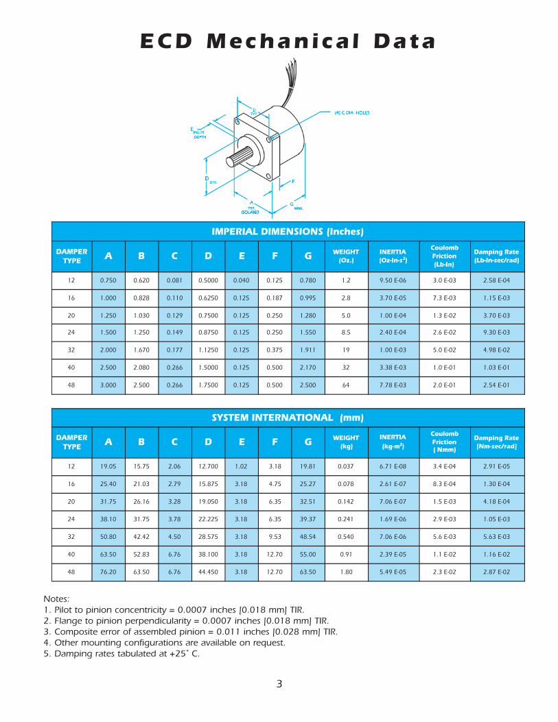
ECD Mechanica l Data
IMPERIAL DIMENSIONS (Inches)
DAMPERTYPE A B C D E F G WEIGHT
(Oz.)INERTIA(Oz-In-s2)
CoulombFriction(Lb-In)
Damping Rate(Lb-In-sec/rad)
12 0.750 0.620 0.081 0.5000 0.040 0.125 0.780 1.2 9.50 E-06 3.0 E-03 2.58 E-04
16 1.000 0.828 0.110 0.6250 0.125 0.187 0.995 2.8 3.70 E-05 7.3 E-03 1.15 E-03
20 1.250 1.030 0.129 0.7500 0.125 0.250 1.280 5.0 1.00 E-04 1.3 E-02 3.70 E-03
24 1.500 1.250 0.149 0.8750 0.125 0.250 1.550 8.5 2.40 E-04 2.6 E-02 9.30 E-03
32 2.000 1.670 0.177 1.1250 0.125 0.375 1.911 19 1.00 E-03 5.0 E-02 4.98 E-02
40 2.500 2.080 0.266 1.5000 0.125 0.500 2.170 32 3.38 E-03 1.0 E-01 1.03 E-01
48 3.000 2.500 0.266 1.7500 0.125 0.500 2.500 64 7.78 E-03 2.0 E-01 2.54 E-01
SYSTEM INTERNATIONAL (mm)
DAMPERTYPE A B C D E F G WEIGHT
(kg)INERTIA(kg-m2)
CoulombFriction( Nmm)
Damping Rate[Nm-sec/rad]
12 19.05 15.75 2.06 12.700 1.02 3.18 19.81 0.037 6.71 E-08 3.4 E-04 2.91 E-05
16 25.40 21.03 2.79 15.875 3.18 4.75 25.27 0.078 2.61 E-07 8.3 E-04 1.30 E-04
20 31.75 26.16 3.28 19.050 3.18 6.35 32.51 0.142 7.06 E-07 1.5 E-03 4.18 E-04
24 38.10 31.75 3.78 22.225 3.18 6.35 39.37 0.241 1.69 E-06 2.9 E-03 1.05 E-03
32 50.80 42.42 4.50 28.575 3.18 9.53 48.54 0.540 7.06 E-06 5.6 E-03 5.63 E-03
40 63.50 52.83 6.76 38.100 3.18 12.70 55.00 0.91 2.39 E-05 1.1 E-02 1.16 E-02
48 76.20 63.50 6.76 44.450 3.18 12.70 63.50 1.80 5.49 E-05 2.3 E-02 2.87 E-02
Notes:1. Pilot to pinion concentricity = 0.0007 inches [0.018 mm] TIR.2. Flange to pinion perpendicularity = 0.0007 inches [0.018 mm] TIR.3. Composite error of assembled pinion = 0.011 inches [0.028 mm] TIR.4. Other mounting configurations are available on request.5. Damping rates tabulated at +25˚ C.
3
4
EPYT SGNITARMUMIXAM )sehcnI(SNOISNEMIDLAIREPMI THGIEW
DAEHRAEG REPMAD
GNIPMADETAR
EUQROTRAEGOITAR A B C D E F G H zO
dar/ces-nI-bL nI-bL -
AA 21 00+E62.3 81 001 057.0 026.0 180.0 5786.0 651.0 881.0 447.1 057.0 0.3
AAA 21 20+E62.3 81 0001 057.0 026.0 180.0 5786.0 651.0 881.0 403.2 057.0 0.4
AAC 21 20+E62.3 48 0001 000.1 828.0 011.0 5739.0 881.0 052.0 183.2 057.0 0.5
AC 61 10+E22.1 48 001 000.1 828.0 011.0 5739.0 881.0 052.0 630.2 000.1 5.6
SCC 61 30+E00.2 48 0821 000.1 828.0 011.0 5739.0 881.0 052.0 579.1 000.1 5.6
ACD 61 30+E22.1 861 0001 052.1 030.1 921.0 5781.1 052.0 052.0 686.2 000.1 5.01
CD 02 10+E95.5 861 701 052.1 030.1 921.0 5781.1 052.0 052.0 704.2 052.1 21
ACD 02 30+E95.5 861 0701 052.1 030.1 921.0 5781.1 052.0 052.0 769.2 052.1 51
CDF 02 30+E11.5 654 0411 005.1 052.1 941.0 5734.1 313.0 313.0 002.3 052.1 81
CD 42 20+E02.1 861 701 005.1 052.1 941.0 5781.1 052.0 313.0 696.2 005.1 71
CDF 42 40+E01.1 654 0411 005.1 052.1 941.0 5734.1 313.0 313.0 194.3 005.1 52
CDH 42 40+E02.1 447 0601 000.2 076.1 771.0 0578.1 573.0 573.0 476.3 005.1 63
DF 23 20+E00.5 654 411 000.2 076.1 771.0 5734.1 313.0 573.0 261.3 000.2 13
CDH 23 40+E48.5 447 0701 000.2 076.1 771.0 0578.1 573.0 573.0 901.4 000.2 65
CCFJ 23 60+E62.2 0051 0446 005.2 260.2 602.0 5734.2 734.0 005.0 099.4 000.2 47
DF 04 30+E50.1 654 201 005.2 260.2 602.0 5734.1 313.0 005.0 005.3 005.2 34
CFJ 04 40+E16.4 0051 466 005.2 260.2 602.0 5734.2 734.0 005.0 055.4 005.2 47
CDHM 04 60+E49.3 0003 0416 000.3 005.2 662.0 7869.2 005.0 005.0 095.6 005.2 001
DH 84 30+E53.2 447 69 000.3 005.2 662.0 0578.1 313.0 057.0 059.3 000.3 09
CFJ 84 50+E03.1 0051 466 000.3 005.2 662.0 5734.2 734.0 057.0 029.4 000.3 501
DFJN 84 60+E01.3 0007 0053 000.4 233.3 573.0 9869.3 265.0 057.0 099.6 000.3 022
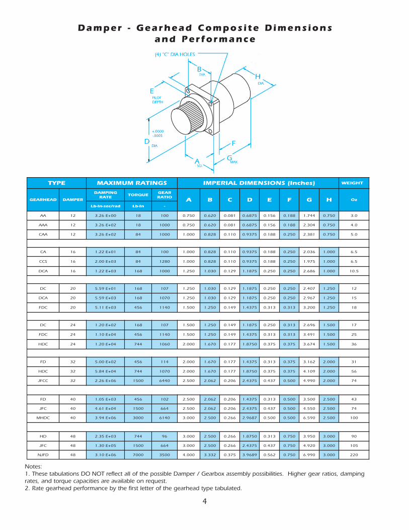
Damper - Gearhead Composi te Dimens ions and Performance
Notes:1. These tabulations DO NOT reflect all of the possible Damper / Gearbox assembly possibilities. Higher gear ratios, dampingrates, and torque capacities are available on request.2. Rate gearhead performance by the first letter of the gearhead type tabulated.
5
EPYT SGNITARMUMIXAM )mm(LANOITANRETNIMETSYS THGIEW
DAEHRAEG REPMAD
GNIPMADETAR
EUQROTRAEGOITAR A B C D E F G H gk
dar/ces-mN mN -
AA 21 10-E86.3 0.2 001 50.91 57.51 60.2 364.71 69.3 87.4 03.44 50.91 580.0
AAA 21 10+E86.3 0.2 0001 50.91 57.51 60.2 364.71 69.3 87.4 25.85 50.91 311.0
AAC 21 10+E86.3 5.9 0001 04.52 30.12 08.2 318.32 87.4 53.6 84.06 50.91 241.0
AC 61 00+E83.1 5.9 001 04.52 30.12 08.2 318.32 87.4 53.6 27.15 04.52 581.0
SCC 61 20+E62.2 5.9 0821 04.52 30.12 08.2 318.32 87.4 53.6 71.05 04.52 581.0
ACD 61 20+E83.1 91 0001 57.13 62.62 03.3 361.03 53.6 53.6 22.86 04.52 892.0
CD 02 00+E23.6 91 701 57.13 61.62 03.3 361.03 53.6 53.6 41.16 57.13 143.0
ACD 02 20+E23.6 91 0701 57.13 61.62 03.3 361.03 53.6 53.6 63.57 57.13 624.0
CDF 02 20+E77.5 25 0411 01.83 57.13 08.3 315.63 59.7 59.7 82.18 57.13 115.0
CD 42 10+E63.1 91 701 01.83 57.13 08.3 361.03 53.6 59.7 87.86 01.83 324.0
CDF 42 30+E42.1 25 0411 01.83 57.13 08.3 315.63 59.7 59.7 76.88 01.83 017.0
CDH 42 30+E63.1 48 0601 08.05 24.24 05.4 312.94 35.9 35.9 13.39 01.83 20.1
DF 23 10+E65.5 25 411 08.05 24.24 05.4 315.63 59.7 35.9 23.08 08.05 188.0
CDH 23 30+E06.6 48 0701 08.05 24.24 05.4 312.94 35.9 35.9 4.401 08.05 95.1
CCFJ 23 50+E55.2 071 0446 05.36 73.25 32.5 319.16 01.11 07.21 0.721 08.05 01.2
DF 04 20+E91.1 25 201 05.36 73.25 32.5 315.63 59.7 07.21 09.88 05.36 22.1
CFJ 04 30+E42.5 071 466 05.36 73.25 32.5 319.16 01.11 07.21 6.511 05.36 01.2
CDHM 04 50+E54.4 043 0416 02.67 05.36 67.6 504.57 07.21 07.21 4.761 05.36 48.2
DH 84 20+E66.2 48 69 02.67 05.36 67.6 312.94 59.7 50.91 3.001 02.67 55.2
CFJ 84 40+E74.1 071 466 02.67 05.36 67.6 319.16 01.11 50.91 0.521 02.67 89.2
DFJN 84 50+E05.3 087 0053 6.101 36.48 35.9 8.001 72.41 50.91 0.871 02.67 52.6
SGNITARDAEHRAEG
daehraeGepyT
"A"eziScisaB
yticapaCeuqroT lanoisroTtnatsnoCgnirpSsuounitnoC tnettimretnI
sehcnI mm nI-bL mN nI-bL mN daR/nI-bL daR/mN
A 057.0 50.91 2.7 18.0 81 30.2 30+E0.6 20+E8.6
C 000.1 04.52 84 4.5 48 5.9 40+E6.1 30+E8.1
D 052.1 57.13 48 5.9 861 91 40+E5.2 30+E8.2
F 005.1 01.83 861 91 654 25 40+E2.4 30+E7.4
H 000.2 08.05 003 43 447 48 40+E4.7 30+E4.8
J 005.2 05.36 447 48 0051 071 50+E8.1 40+E0.2
M 000.3 02.67 0021 631 0003 043 50+E0.6 40+E8.6
N 000.4 06.101 0063 704 0096 087 60+E6.3 50+E1.4
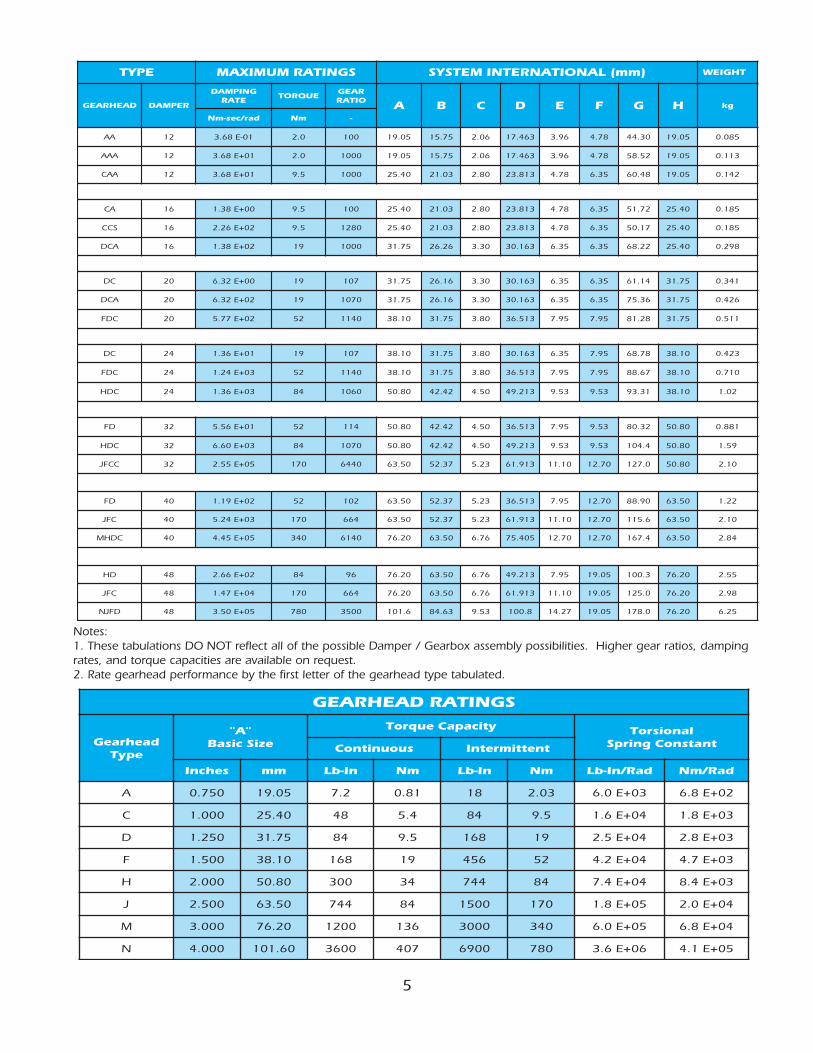
Notes:1. These tabulations DO NOT reflect all of the possible Damper / Gearbox assembly possibilities. Higher gear ratios, dampingrates, and torque capacities are available on request.2. Rate gearhead performance by the first letter of the gearhead type tabulated.
6
EPYT SGNITARMUMIXAM LAIREPMI )sehcnI(SNOISNEMID THGIEW
DAEHRAEG REPMADGNIPMAD EUQROT
RAEGOITAR
A B C D E F G H J K L M N .ZO
dar/ces-nI-bL nI-bL -
ARA 21 00+E63.2 81 781 057.0 026.0 922.0 180.0 041.0 573.0 031.2 338.0 634.0 881.0 0537.0 052.0 057.0 3.4
AARC 21 20+E63.2 48 0781 000.1 828.0 003.0 011.0 491.0 005.0 050.3 071.1 495.0 052.0 0579.0 313.0 057.0 0.8
ACRD 21 20+E86.2 861 1991 572.1 030.1 004.0 921.0 912.0 736.0 513.3 782.1 226.0 052.0 0052.1 313.0 057.0 41
ARC 61 10+E62.4 48 781 000.1 828.0 003.0 011.0 491.0 005.0 086.2 071.1 495.0 052.0 0579.0 313.0 000.1 01
ACRD 61 30+E38.4 861 1991 572.1 030.1 004.0 921.0 912.0 736.0 035.3 782.1 226.0 052.0 0052.1 313.0 000.1 61
CDRF 61 30+E85.8 654 1191 525.1 052.1 044.0 941.0 272.0 367.0 059.3 045.1 097.0 573.0 0005.1 573.0 000.1 32
CRD 02 20+E39.1 861 991 572.1 030.1 004.0 921.0 912.0 736.0 232.3 782.1 226.0 052.0 0052.1 313.0 052.1 71
CDRF 02 40+E87.1 654 1191 525.1 052.1 044.0 941.0 272.0 367.0 062.4 045.1 097.0 573.0 0005.1 573.0 052.1 52
CDRH 02 40+E87.1 447 1191 000.2 076.1 585.0 771.0 613.0 000.1 926.4 260.2 260.1 573.0 0579.1 574.0 052.1 04
DRF 42 20+E38.1 654 191 525.1 052.1 044.0 941.0 272.0 367.0 558.3 045.1 097.0 573.0 0005.1 573.0 005.1 82
CDRH 42 40+E88.3 447 1191 000.2 076.1 585.0 771.0 613.0 000.1 292.4 260.2 260.1 573.0 0579.1 574.0 005.1 34
DFRJ 42 40+E20.2 0051 7831 005.2 060.2 057.0 602.0 034.0 052.1 007.5 265.2 213.1 005.0 0574.2 265.0 005.1 27
DRH 23 30+E68.1 447 191 000.2 076.1 585.0 771.0 613.0 000.1 275.4 260.2 260.1 573.0 0579.1 574.0 000.2 25
DFRJ 23 40+E39.8 0051 3231 005.2 060.2 057.0 602.0 034.0 052.1 160.6 265.2 213.1 005.0 0574.2 265.0 000.2 58
DFRM 23 40+E07.6 0003 6411 005.3 057.2 052.1 662.0 006.0 057.1 059.6 313.3 318.1 526.0 0052.3 526.0 000.2 061
FRJ 04 30+E16.1 0051 421 005.2 060.2 057.0 602.0 034.0 052.1 016.5 265.2 213.1 005.0 0574.2 265.0 005.2 59
DFRJ 04 50+E48.1 0051 3231 005.2 060.2 057.0 602.0 034.0 052.1 042.6 265.2 213.1 005.0 0574.2 265.0 005.2 011
DFRM 04 50+E83.1 0003 6411 005.3 057.2 052.1 662.0 006.0 057.1 032.7 313.3 318.1 526.0 0052.3 526.0 005.2 012
FRM 84 30+E29.2 0003 701 005.3 057.2 052.1 662.0 006.0 057.1 019.6 313.3 318.1 526.0 0052.3 526.0 000.3 522
DFRM 84 50+E53.3 0003 6411 005.3 057.2 052.1 662.0 006.0 057.1 035.7 313.3 318.1 526.0 0052.3 526.0 000.3 052
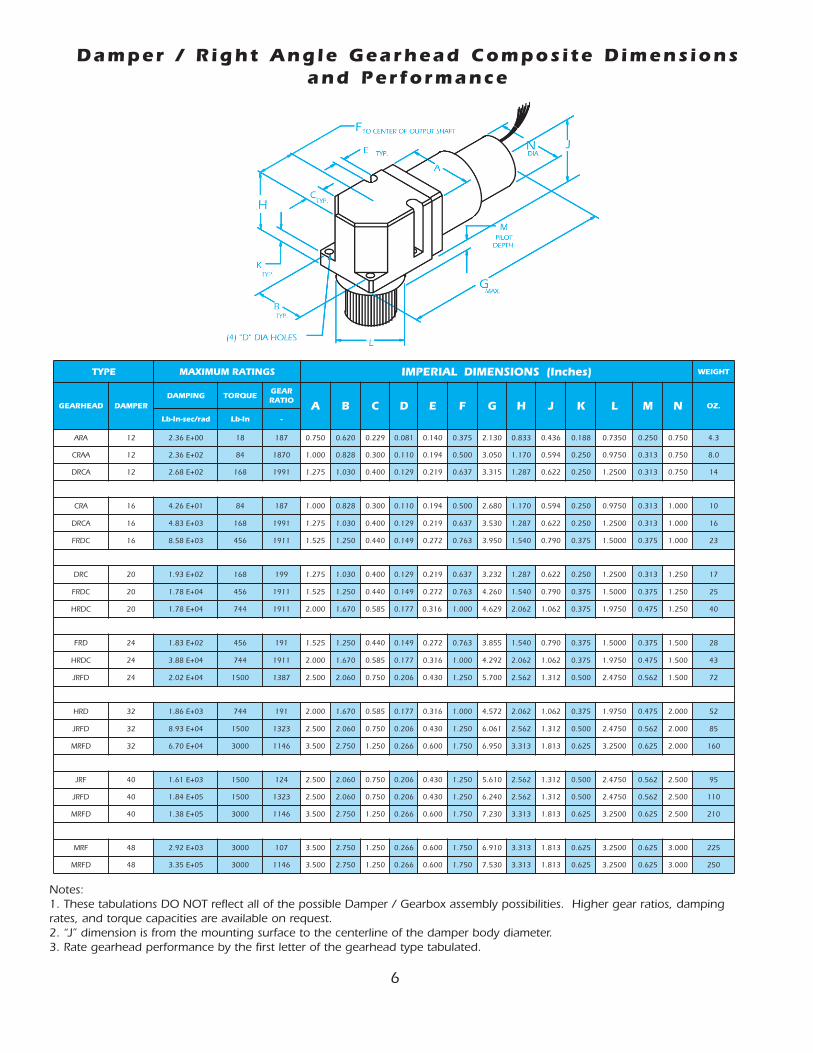
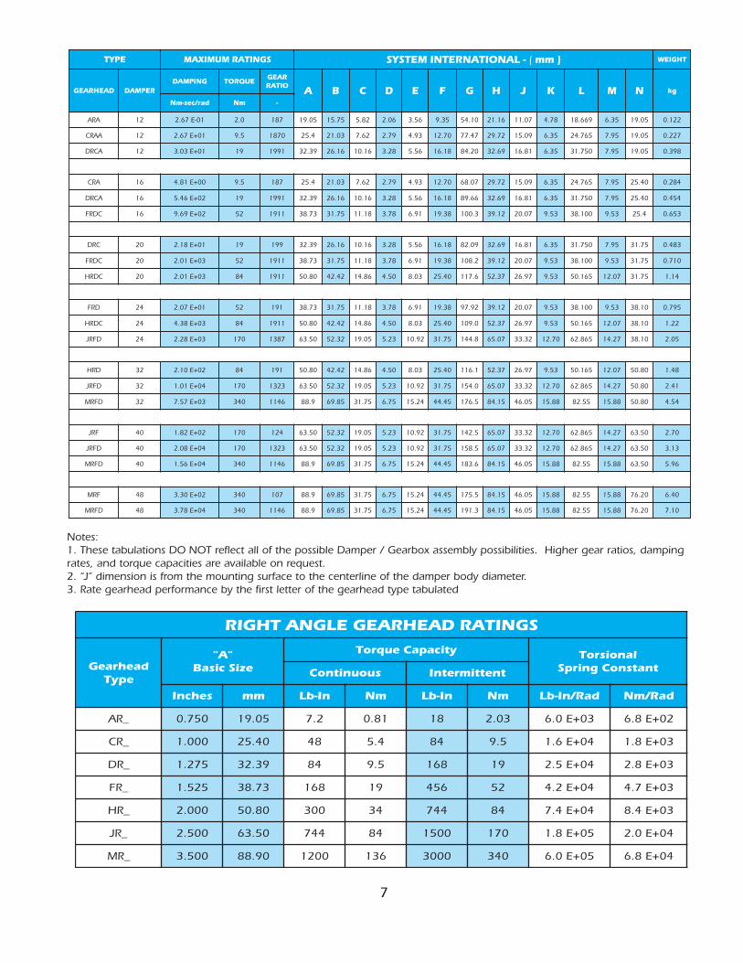
Damper / R ight Angle Gearhead Composi te Dimens ions and Performance
Notes:1. These tabulations DO NOT reflect all of the possible Damper / Gearbox assembly possibilities. Higher gear ratios, dampingrates, and torque capacities are available on request.2. “J” dimension is from the mounting surface to the centerline of the damper body diameter.3. Rate gearhead performance by the first letter of the gearhead type tabulated.
7
EPYT SGNITARMUMIXAM -LANOITANRETNIMETSYS ( )mm THGIEW
DAEHRAEG REPMADGNIPMAD EUQROT
RAEGOITAR
A B C D E F G H J K L M N gk
dar/ces-mN mN -
ARA 21 10-E76.2 0.2 781 50.91 57.51 28.5 60.2 65.3 53.9 01.45 61.12 70.11 87.4 966.81 53.6 50.91 221.0
AARC 21 10+E76.2 5.9 0781 4.52 30.12 26.7 97.2 39.4 07.21 74.77 27.92 90.51 53.6 567.42 59.7 50.91 722.0
ACRD 21 10+E30.3 91 1991 93.23 61.62 61.01 82.3 65.5 81.61 02.48 96.23 18.61 53.6 057.13 59.7 50.91 893.0
ARC 61 00+E18.4 5.9 781 4.52 30.12 26.7 97.2 39.4 07.21 70.86 27.92 90.51 53.6 567.42 59.7 04.52 482.0
ACRD 61 20+E64.5 91 1991 93.23 61.62 61.01 82.3 65.5 81.61 66.98 96.23 18.61 53.6 057.13 59.7 04.52 454.0
CDRF 61 20+E96.9 25 1191 37.83 57.13 81.11 87.3 19.6 83.91 3.001 21.93 70.02 35.9 001.83 35.9 4.52 356.0
CRD 02 10+E81.2 91 991 93.23 61.62 61.01 82.3 65.5 81.61 90.28 96.23 18.61 53.6 057.13 59.7 57.13 384.0
CDRF 02 30+E10.2 25 1191 37.83 57.13 81.11 87.3 19.6 83.91 2.801 21.93 70.02 35.9 001.83 35.9 57.13 017.0
CDRH 02 30+E10.2 48 1191 08.05 24.24 68.41 05.4 30.8 04.52 6.711 73.25 79.62 35.9 561.05 70.21 57.13 41.1
DRF 42 10+E70.2 25 191 37.83 57.13 81.11 87.3 19.6 83.91 29.79 21.93 70.02 35.9 001.83 35.9 01.83 597.0
CDRH 42 30+E83.4 48 1191 08.05 24.24 68.41 05.4 30.8 04.52 0.901 73.25 79.62 35.9 561.05 70.21 01.83 22.1
DFRJ 42 30+E82.2 071 7831 05.36 23.25 50.91 32.5 29.01 57.13 8.441 70.56 23.33 07.21 568.26 72.41 01.83 50.2
DRH 23 20+E01.2 48 191 08.05 24.24 68.41 05.4 30.8 04.52 1.611 73.25 79.62 35.9 561.05 70.21 08.05 84.1
DFRJ 23 40+E10.1 071 3231 05.36 23.25 50.91 32.5 29.01 57.13 0.451 70.56 23.33 07.21 568.26 72.41 08.05 14.2
DFRM 23 30+E75.7 043 6411 9.88 58.96 57.13 57.6 42.51 54.44 5.671 51.48 50.64 88.51 55.28 88.51 08.05 45.4
FRJ 04 20+E28.1 071 421 05.36 23.25 50.91 32.5 29.01 57.13 5.241 70.56 23.33 07.21 568.26 72.41 05.36 07.2
DFRJ 04 40+E80.2 071 3231 05.36 23.25 50.91 32.5 29.01 57.13 5.851 70.56 23.33 07.21 568.26 72.41 05.36 31.3
DFRM 04 40+E65.1 043 6411 9.88 58.96 57.13 57.6 42.51 54.44 6.381 51.48 50.64 88.51 55.28 88.51 05.36 69.5
FRM 84 20+E03.3 043 701 9.88 58.96 57.13 57.6 42.51 54.44 5.571 51.48 50.64 88.51 55.28 88.51 02.67 04.6
DFRM 84 40+E87.3 043 6411 9.88 58.96 57.13 57.6 42.51 54.44 3.191 51.48 50.64 88.51 55.28 88.51 02.67 01.7
Notes:1. These tabulations DO NOT reflect all of the possible Damper / Gearbox assembly possibilities. Higher gear ratios, dampingrates, and torque capacities are available on request.2. “J” dimension is from the mounting surface to the centerline of the damper body diameter.3. Rate gearhead performance by the first letter of the gearhead type tabulated
SGNITARDAEHRAEGELGNATHGIR
daehraeGepyT
"A"eziScisaB
yticapaCeuqroT lanoisroTtnatsnoCgnirpSsuounitnoC tnettimretnI
sehcnI mm nI-bL mN nI-bL mN daR/nI-bL daR/mN
_RA 057.0 50.91 2.7 18.0 81 30.2 30+E0.6 20+E8.6
_RC 000.1 04.52 84 4.5 48 5.9 40+E6.1 30+E8.1
_RD 572.1 93.23 48 5.9 861 91 40+E5.2 30+E8.2
_RF 525.1 37.83 861 91 654 25 40+E2.4 30+E7.4
_RH 000.2 08.05 003 43 447 48 40+E4.7 30+E4.8
_RJ 005.2 05.36 447 48 0051 071 50+E8.1 40+E0.2
_RM 005.3 09.88 0021 631 0003 043 50+E0.6 40+E8.6

8
SNOITAUQEGNIPMADDNAERUTALCNEMON
lobmyS noitpircseD stinU noitauqErotnemmoC
BD
repmaDdeepShgiHehtfoetaRgnipmaDdar/ces-nI-bL
]dar/ces-mN[3egapnodetalubaT
BtD
tarepmaDdeepShgiHfoetaRgnipmaD
C˚52+nahtrehto)t(erutarepmeT
dar/ces-nI-bL
]dar/ces-mN[B
tDB=
D))52-t(400.0-1(
BG
ehtotdetcelfeRxobraeGehtfoetaRgnipmaD
repmaDdeepShgiH
dar/ces-nI-bL
]dar/ces-mN[B:yllacipyT
GB=
tD52.0*
BT
hgiHehtotdetcelfeRetaRgnipmaDlatoT
repmaDdeepS
dar/ces-nI-bL
]dar/ces-mN[B
TB=
DB+
G
BL
ylbmessAxobraeG-repmaDfoetaRgnipmaD
tupnIdeepSwoLehtotdetcelfeR
dar/ces-nI-bL
]dar/ces-mN[B
LB=
TN* 2
BDL
daoLehttaetaRgnipmaDcimanyD
)tniopynataetargnipmadsuoenatnatsnI(
dar/ces-nI-bL
]dar/ces-mN[BD
LT=
L/ ω
L
FD
noitcirF)citatsro(bmoluoC
repmaDdeepShgiHfo
nI-bL
]mN[3egapnodetalubaT
FG
ehtotdetcelfeR,xobraeGfonoitcirFbmoluoC
repmaDdeepShgiH
nI-bL
]mN[
nI-bL10.0yllacipyT
]mN30-E21.1[
FT
hgiHehtotdetcelfeR,noitcirFbmoluoClatoT
repmaDdeepS
nI-bL
]mN[F
TF=
DF+
G
FL
xobraeG-repmaDehtfonoitcirFbmoluoC
tupnIdeepSwoLehtotdetcelfeR,ylbmessA
nI-bL
]mN[F
LF=
TN*
NoitaRxobraeG
neviG( ωL
TdnaL
)repmadnevigarofNdnif,- B2(/1((=N
T*ω
LF-(*))
T2 B4+
T*ω
LT*
L) 5.0 )
TL
daoLtatupnIeuqroTnI-bL
]mN[T
LB(=
L* ω
LF+)
L
ωL yticoleVralugnAdaoL ces/dar ω
LT(=
LF-
LB/)
L
:setoN
.C˚52+taecnamrofreplanimontcelfersnoitauqeevobaeht,detatsesiwrehtosselnU.1
BdaehraeG.2G
FdnaG
.seulavlanimonelbanosaertcelfersetamitseeseht,revewoh,oitardnaezisemarfhtiwyravyam
.noitamrofnirehtrufroftnemtrapedgnireenignes'proCretnIADCtlusnoC.3
ECD Nomenclature and Damper Equations
TEEHSREVOCXAF
:oT Attention:
Date:
Company:
Name:
Mail Stop:
Subject:
Company:
Fax No:
Reference:
Phone No:
FAX No.:
e-mail:
Phone No.:
ADC rpoCretnI
gnireenignEnoitacilppA
Request for Information
1106-896-459
0006-896-459
:MORF
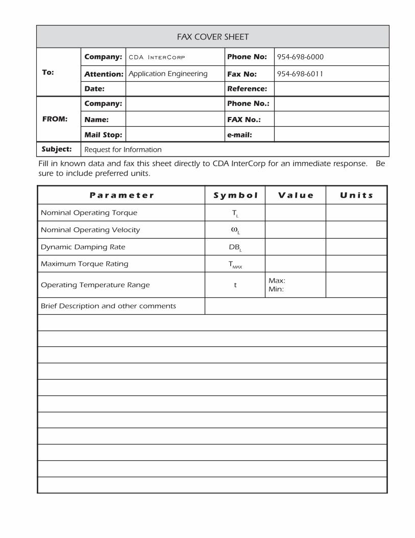
retemaraP lobmyS eulaV stinU
euqroTgnitarepOlanimoN TL
yticoleVgnitarepOlanimoN ωL
etaRgnipmaDcimanyD BDL
gnitaReuqroTmumixaM TXAM
egnaRerutarepmeTgnitarepO t:xaM:niM
stnemmocrehtodnanoitpircseDfeirB
Fill in known data and fax this sheet directly to CDA InterCorp for an immediate response. Besure to include preferred units.

CCDDAA IInntteerrCCoorrpp450 Goolsby BoulevardDeerf i e ld , FL 33442-3019
tel (954) 698-6000 • fax (954) 698-6011http://www.cda- in tercorp.com
© 2000 CDA InterCorp - A l l R ights Reser ved02/06
Motor Modules :• Brush less Permanent Magnet
Motors• AC Induct ion Motors• S tepper Motors• Square Wave Dr iven AC Motors• Damped Rotar y Swi tches• Housed L imi ted Angle Torquers• Synchronous Motors
Eddy Current Dampers :• Rotar y • L inear• In L ine or R ight Angle• Damping “enable” opt ion
Gear ing Modules :Rotar y :
• High Torque P lanetar y• R ight Angle Gear ing • High Accuracy Zero Back lash
Gear ing• Prec i s ion Index ing Dr ive Gear ing
L inear :• Ba l l Sc rew Actuat ion• ACME Lead Screw Actuat ion• In - l ine , R ight -angle , or U-dr ive
Brakes :• DC Fr ic t ion Brakes• Permanent Magnet Detent
Brakes• DC Hysteres i s Brakes
Transducers :Pos i t ion Transducers :
• Brush less Reso lvers• S ing le Speed • Mul t ip le Speed• Tandem or C lus ter
Redundant• Wi th or wi thout Gear ing• OnAx is Reso lvers
• R VDT ’s• Tandem or C lus ter Redundancy• Wi th or wi thout Gear ing• OnAx is R VDT
Veloc i ty Transducers :• AC Tachometers
• Damping Tachs• Rate Tachs
• Permanent Magnet A l ternators• S ing le Speed• Mul t ip le Speed• Wi th or wi thout Gear ing
Acce lerat ion Transducers :•Brush less DC Rotar y Acce lerometers•DC Exc i ted Rotar y Acce lerometers
CDA InterCorp can combine these s tandardmodules in to mul t i - funct ion in tegrated actua -t o r s a n d a s s e m b l i e s . C a l l C D A I n t e r C o r pd i re c t l y f o r a p p l i c a t i o n e n g i n e e r i n g a s s i s -tance, or to request a complete se t o f app l i -ca t ion data brochures .
CDA InterCorp Products


