142 CES TRANSACTIONS ON ELECTRICAL MACHINES AND SYSTEMS, VOL. 2, NO. 1, MARCH 2018 Abstract—This paper focuses on the controller design using fuzzy sliding mode control (FSMC) with application to electro-mechanical brake (EMB) systems using BLDC Motor. The EMB controller transmits the control signal to the motor driver to rotate the motor. The torque distribution of motors is studied in this paper actually. Firstly, the model of the EMB system is established. Then the state observer is developed to estimate the vehicle states including the vehicle velocity and longitudinal force. Due to the fact that the EMB system is nonlinear and uncertain, a FSMC strategy based on wheel slip ratio is proposed, where both the normal and emergency braking conditions are taken into account. The equivalent control law of sliding mode controller is designed on the basis of the variation of the front axle and rear axle load during the brake process, while the switching control law is adjusted by the fuzzy corrector. The simulation results illustrate that the FSMC strategy has the superior performance, better adaptability to various types of roads, and shorter braking distance, as compared to PID control and traditional sliding mode control technologies. Finally, the hardware-in-loop (HIL) experimental results have exemplified the validation of the developed methodology. Index Terms—BLDC Motor, electro-mechanical brake, fuzzy sliding mode control, longitudinal force estimation, hardware-in-loop experiments, wheel slip ratio. This article was submitted for review on 31, January, 2018. This work was supported by the National Natural Science Foundation of China under Grant [number 51575167]. Xiaoyan Peng is with State Key Laboratory of Advanced Design and Manufacturing for Vehicle Body, College of Mechanical and Vehicle Engineering, Hunan University, Changsha, 410000, China. She is currently a professor in Hunan University. (e-mail: [email protected]) Mingfei Jia is with College of Mechanical and Vehicle Engineering, Hunan University, Changsha, 410000, China. (e-mail:[email protected]) Lei He received the B.S. and M.S. degrees in mechanical engineering and Mechanical electronic engineering from Hunan University, Changsha, China, in 2013and 2016, respectively. (e-mail: [email protected]) Xiang Yu is currently working at Concordia University, Montreal, Canada.(e-mail: [email protected]) Yibin Lv received the B.S. and M.S. degrees in mechanical engineering and Mechanical electronic engineering from Hunan University, Changsha, China, in 2013 and 2016, respectively.(e-mail: [email protected]) I. INTRODUCTION RAKE-BY-WIRE(BBW) system in electric vehicles(EVs) have drawn significant interest due to the great potential in real applications. BBW systems can have a more compact structure and a higher braking efficiency without the traditional hydraulic components. In addition, the torque from a BBW system can react 10-100 times faster than that of a hydraulic braking system [1]. On the other hand, within a BBW scheme, the optimum braking pressure can be calculated for each wheel and the braking force of each wheel can be independently controlled [2]. As a result, BBW systems are capable of offering a higher level of safety rather than conventional braking systems. In contrast to electro-hydraulic brake systems, the electro-mechanical brake (EMB) system without any hydraulic backups is constructed by electric and electro-mechanical components. Thus, the EMB system requires more precise control than a conventional brake system [3]. Wheel slip ratio, which can be obtained from the speeds of the wheel and the vehicle, can be used to estimate the longitudinal and lateral forces of the tire in real time [4-5]. Furthermore, the estimated tire longitudinal forces and slip rate can be used to estimate the road friction coefficient and the optimal slip ratio, which can ensure the maximum use of the ground adhesion and improve the braking performance [6-7]. Wheel slip control has been a central of research focus in recent years. Daimler Chrysler first designs a gain-scheduled wheel slip controller for EMB systems with Norwegian University of Science and Technology [8], and then develops a gain-scheduled nonlinear PI controller with Lund Institute of Technology [9]. In [10], the optimal slips are estimated by monitoring the behaviours of the rear wheels, while the front wheels are controlled to track the optimal slips in an antilock brake system (ABS). In [11], a set of multiple-model switching (MMS) lead-lag controllers for EMB systems are adapted according to a variety of road conditions. Meanwhile, a multiple-model switching observer is developed to estimate the varying friction coefficient and the varying optimal slips. In [12], wheel slip control is integrated into the design of the hybrid ABS. However, the existing literature is mainly aimed at the emergency braking condition such as ABS, without Fuzzy Sliding Mode Control Based on Longitudinal Force Estimation for Electro-mechanical Braking Systems using BLDC Motor Xiaoyan Peng, Mingfei Jia, Lei He, Xiang Yu and Yibin Lv B
Transcript
142 CES TRANSACTIONS ON ELECTRICAL MACHINES AND SYSTEMS, VOL. 2, NO. 1, MARCH 2018
Abstract—This paper focuses on the controller design
using fuzzy sliding mode control (FSMC) with application to electro-mechanical brake (EMB) systems using BLDC Motor. The EMB controller transmits the control signal to the motor driver to rotate the motor. The torque distribution of motors is studied in this paper actually. Firstly, the model of the EMB system is established. Then the state observer is developed to estimate the vehicle states including the vehicle velocity and longitudinal force. Due to the fact that the EMB system is nonlinear and uncertain, a FSMC strategy based on wheel slip ratio is proposed, where both the normal and emergency braking conditions are taken into account. The equivalent control law of sliding mode controller is designed on the basis of the variation of the front axle and rear axle load during the brake process, while the switching control law is adjusted by the fuzzy corrector. The simulation results illustrate that the FSMC strategy has the superior performance, better adaptability to various types of roads, and shorter braking distance, as compared to PID control and traditional sliding mode control technologies. Finally, the hardware-in-loop (HIL) experimental results have exemplified the validation of the developed methodology.
Index Terms—BLDC Motor, electro-mechanical brake, fuzzy sliding mode control, longitudinal force estimation, hardware-in-loop experiments, wheel slip ratio.
This article was submitted for review on 31, January, 2018. This work was supported by the National Natural Science Foundation of
China under Grant [number 51575167]. Xiaoyan Peng is with State Key Laboratory of Advanced Design and
Manufacturing for Vehicle Body, College of Mechanical and Vehicle Engineering, Hunan University, Changsha, 410000, China. She is currently a professor in Hunan University. (e-mail: [email protected])
Mingfei Jia is with College of Mechanical and Vehicle Engineering, Hunan University, Changsha, 410000, China. (e-mail:[email protected])
Lei He received the B.S. and M.S. degrees in mechanical engineering and Mechanical electronic engineering from Hunan University, Changsha, China, in 2013and 2016, respectively. (e-mail: [email protected])
Xiang Yu is currently working at Concordia University, Montreal, Canada.(e-mail: [email protected])
Yibin Lv received the B.S. and M.S. degrees in mechanical engineering and Mechanical electronic engineering from Hunan University, Changsha, China, in 2013 and 2016, respectively.(e-mail: [email protected])
I. INTRODUCTION RAKE-BY-WIRE(BBW) system in electric vehicles(EVs) have drawn significant interest due to the great potential in
real applications. BBW systems can have a more compact structure and a higher braking efficiency without the traditional hydraulic components. In addition, the torque from a BBW system can react 10-100 times faster than that of a hydraulic braking system [1]. On the other hand, within a BBW scheme, the optimum braking pressure can be calculated for each wheel and the braking force of each wheel can be independently controlled [2]. As a result, BBW systems are capable of offering a higher level of safety rather than conventional braking systems. In contrast to electro-hydraulic brake systems, the electro-mechanical brake (EMB) system without any hydraulic backups is constructed by electric and electro-mechanical components. Thus, the EMB system requires more precise control than a conventional brake system [3].
Wheel slip ratio, which can be obtained from the speeds of the wheel and the vehicle, can be used to estimate the longitudinal and lateral forces of the tire in real time [4-5]. Furthermore, the estimated tire longitudinal forces and slip rate can be used to estimate the road friction coefficient and the optimal slip ratio, which can ensure the maximum use of the ground adhesion and improve the braking performance [6-7]. Wheel slip control has been a central of research focus in recent years. Daimler Chrysler first designs a gain-scheduled wheel slip controller for EMB systems with Norwegian University of Science and Technology [8], and then develops a gain-scheduled nonlinear PI controller with Lund Institute of Technology [9]. In [10], the optimal slips are estimated by monitoring the behaviours of the rear wheels, while the front wheels are controlled to track the optimal slips in an antilock brake system (ABS). In [11], a set of multiple-model switching (MMS) lead-lag controllers for EMB systems are adapted according to a variety of road conditions. Meanwhile, a multiple-model switching observer is developed to estimate the varying friction coefficient and the varying optimal slips. In [12], wheel slip control is integrated into the design of the hybrid ABS. However, the existing literature is mainly aimed at the emergency braking condition such as ABS, without
Fuzzy Sliding Mode Control Based on Longitudinal Force Estimation for
Electro-mechanical Braking Systems using BLDC Motor
Xiaoyan Peng, Mingfei Jia, Lei He, Xiang Yu and Yibin Lv
B
PENG et al. : FUZZY SLIDING MODE CONTROL BASED ON LONGITUDINAL FORCE ESTIMATION FOR ELECTRO-MECHANICAL 143 BRAKING SYSTEMS USING BLDC MOTOR
considering the normal braking condition. The EMB system is nonlinear and uncertain, establishing an
accurate mathematical model becomes difficult. Thus the controller must be robust on the uncertainties caused by the tire characteristics, brake pads/disks, the road surface conditions, and load on the vehicle. Sliding mode control (SMC) is recognized as an option of addressing the afore-mentioned problems, due to the advantages of rapid response, insensitivity to parameters change, and strong robustness. In [13-14], an observer-based sliding mode controller has been synthesized for semi-Markovian jump systems with mismatched uncertainties to guarantee the reachability of the system’s trajectories to the predefined integral-type sliding surface. With the development of technology, sliding mode control has obvious advantages for nonlinear and uncertain system control, such as EMB system. In [15-16], the SMC technique is exploited to design wheel slip controllers for EMB systems. The findings in [16] exhibit that the control performance and the adaptability to various road conditions are superior to PID control. However, the existing methods ignore the changes of axles load, degrading the control performance. Furthermore, the chattering issue of SMC has an adverse impact on the control precision and the stability margin [17]. In [18-19], a T-S fuzzy model for nonlinear Markov jump systems is designed to analyze and synthesize the nonlinear physical systems and processes. Fuzzy model can describe non-linear, state-delay system characteristics reliably. Fuzzy algorithm can adaptively tune the switching gain of the sliding mode method, effectively avoiding the impact of the chattering issue.
EMB system is a brand new brake system, there are many new challenges when design its control system. This article aims to design a control system and control strategy for EMB to improve its control quality. In this paper, a wheel slip control architecture for EMB systems is presented. Within the proposed scheme, 1) the normal and emergency braking conditions are explicitly taken into account, under normal braking conditions, the axial slip ratio is re-distributed according to the axial load transfer. 2) The optimal slips and the corresponding road friction coefficient are obtained by an optimal wheel slip ratio estimator, whilst the vehicle velocity and longitudinal force are estimated by the corresponding observers, which are based on the Kalman filter. And 3) aiming at the problem of EMB nonlinearity, a fuzzy sliding mode control (FSMC) strategy based on wheel slip ratio for the EMB system is proposed. The equivalent control law is designed on the basis of the variation of the front and rear axle load during the braking process, and the switching control law is adjusted by the fuzzy corrector to suppress the chattering issue.
The rest of this paper is arranged as follows. Section 2 introduces the configuration of the EMB system and developed models. Section 3 designs the state observers. Section 4 presents the FSMC strategy for EMB controllers. Results of the simulation analysis are illustrated in Section 5. Section 6 shows the hardware-in-loop (HIL) experimental results, which validate the effectiveness of the proposed scheme. Lastly, concluding remarks are drawn in Section 7.
II. EMB SYSTEM MODEL The control architecture base on wheel slip ratio for EMB
systems is shown in Fig. 1. The notations used are listed in Table 1.
Fig. 1. Block diagram of the EMB control system based on wheel slip ratio.
The braking force allocation controller changes different operating modes, according to the comparison between z and ˆ pμ . If ˆ pz μ≤ holds, the vehicle is identified in the normal
braking condition. Thereby λ∗ can be calculated by an optimal braking force allocation strategy. Otherwise, the vehicle is in the emergency braking condition, under which the braking force allocation controller drives λ∗ equals to ˆ
pλ . The EMB controller is designed based on the dynamic relation such that λ can converge to ˆ
pλ . In this case, the proposed control system can work under both normal and emergency braking conditions.
TABLE I NOTATIONS USED IN FIGURE 1
Symbol Description
z Target severity of braking ˆ
pλ Observed optimal wheel slip ratio
ˆ pμ Observed peak road friction coefficient
λ∗ Target wheel slip ratio
λ Observed current wheel slip ratio
u Observed current road friction coefficient
ˆxF Observed longitudinal force
ˆzF Observed normal force
aI Armature current
bT Brake torque
v Measured vehicle acceleration
v Observed vehicle velocity ω Measured angular velocity of the wheel
A. Half-vehicle Dynamic Model The following assumptions are made before presenting a
half-vehicle dynamic model. Firstly, straight-line braking is performed on a flat road. Secondly, the air resistance torque, rolling resistance torque, and inertia moment of gyrating mass
144 CES TRANSACTIONS ON ELECTRICAL MACHINES AND SYSTEMS, VOL. 2, NO. 1, MARCH 2018
are ignored in the braking process. Thirdly, left and right wheel load is identical. The half-vehicle dynamic model is established to describe the force of vehicle, as depicted in Fig. 2.
Fig. 2. Half-vehicle dynamic model.
The vehicle longitudinal dynamics can be described as: ( )1 2 3 4x x x xmv F F F F= − + + + (1)
The wheel dynamics equation is expressed as: i i wi xi biJ R F Tω = − (2) where subscripts 1,2,3,4i = indicate the left front wheel, right front wheel, left rear wheel, and right rear wheel, respectively, m is the vehicle mass, xiF is the longitudinal force of the ith wheel, iJ is the mass moment inertia of the ith wheel, iω is angular acceleration of the ith wheel, wiR is the wheel radius of the ith wheel, and biT is the brake torque applied to the ith wheel.
The longitudinal force of the ith wheel, xiF is calculated as: xi zi iF F μ= (3) where iμ is the current road friction coefficient of the ith wheel. The normal force of the ith wheel, ziF , can be determined according to:
( )
( )
1 2
3 4
2
2
z z
z z
mF F bg vHL
mF F ag vHL
⎧ = = +⎪⎪⎨⎪ = = −⎪⎩
(4)
where g is the gravitational acceleration, L is the wheelbase, a and b represent the distance from the front axle to the centroid and the distance from the rear axle to the centroid, respectively, and H is the height of the centroid of the vehicle.
The wheel slip ratio of the ith wheel, iλ can be determined on the basis of:
wi ii
v Rv
ωλ
−= (5)
where v is the vehicle velocity.
B. Burckhardt Tire Model Burckhardt tire model is employed to describe the nonlinear
characteristics of the μ λ− curve in the absence of vehicle velocity and tire load effects, which is written as [20]: ( ) ( )2
1 31 cc e cλμ λ λ−= − − (6) where 1c , 2c , and 3c are parameters fitted by experimental data. The selection of these parameters on different road
surface can be found in [21], while the details are omitted herein for the sake of brevity.
C. EMB Actuator Model The EMB actuator consists of a motor, a planetary-type
reduction gear, a screw-thread gear, a pair of brake pads, and a brake disk. The EMB controller transmits the control signal to the motor driver to rotate the motor. The rotational motion of the motor is transformed into a linear motion of the pad via the planetary-type reduction gear and the screw-thread gear. A clamping force between the pad and the disk is generated by the linear motion of the pad, generating the braking torque [22]. 1) Motor
A DC torque motor is studied in this paper. After the brake pads contact with the brake disk, the motor keeps the locked-rotor state. The output torque of the motor is: d e fT T T= − (7) where dT , eT and fT denote the output torque, the
electromagnetic torque, and the friction torque of motor, respectively. eT is given as: e T aT K I= (8) where TK is the motor torque constant. fT , which can be
regarded as the static friction torque at the locked-rotor state, is represented as:
( )
,
sgn , e e s
fs e e s
T T TT
T T T T
⎧ <⎪= ⎨⋅ ≥⎪⎩
(9)
where sT is the maximum static friction torque. Substituting Equations (8) and (9) into Equation (7) yields:
0,
,e s
dT a s e s
T TT
K I T T T
⎧ <⎪= ⎨⋅ − ≥⎪⎩
(10)
2) Planetary-type Reduction Gear In this paper, a reduction gear that uses a planetary gear set is
employed. The motor power is transmitted through the reduction gear to the screw. The output torque of the planetary-type reduction gear, xT , is represented as: x d x xT T i η= ⋅ ⋅ (11) where xi is the torque ratio of the planetary-type reduction gear and xη describes the torque efficiency of the planetary-type reduction gear. 3) Screw-thread Gear
The screw-thread gear transforms the rotational motion of the screw to the linear motion of the gear. The force from the gear to the brake pad can be expressed as:
2 x s
h
TN
Pπ η⋅ ⋅
= (12)
where N specifies the clamping force, sη denotes the torque efficiency of the screw-thread gear, and hP is the pitch of the screw thread.
D. Brake Torque The friction force is generated by the movement between the
PENG et al. : FUZZY SLIDING MODE CONTROL BASED ON LONGITUDINAL FORCE ESTIMATION FOR ELECTRO-MECHANICAL 145 BRAKING SYSTEMS USING BLDC MOTOR
disk and the pads. The friction torque, which is called the brake torque, is produced under the effect of the friction force acting on the tire. Provided that the effective radius of the brake disk and the friction coefficient of the brake pad are known, the brake torque can be calculated as: 2b b bT N Rμ= ⋅ ⋅ (13) where bμ is the friction coefficient of the brake pad and bR is the effective radius of the brake disk. bT can be obtained by substituting Equations. (10)-(12) into Equation (13):
( )
0,
, e s
bb T a s e s
T TT
k K I T T T
⎧ <⎪= ⎨⋅ − ≥⎪⎩
(14)
where 4 b b s x x
bh
R ikP
πμ η η= is the brake torque constant.
III. VEHICLE ESTATE ESTIMATION The EMB control system described in the previous section
needs the information of the vehicle velocity, the longitudinal force, and the optimal wheel slip ratio. In practice, it is normally difficult to measure the longitudinal force of each wheel and the vehicle velocity. Moreover, the optimal wheel slip ratio needs to be estimated by current wheel slip ratio and corresponding road friction coefficient. With consideration of these facts, the state observers are designed in this section.
A. Vehicle Velocity Observer The vehicle velocity is estimated based on the measurement
of vehicle acceleration. A velocity observer proposed in [11] is used in the present study:
( ) ( )
( ) ( ) ( ) ( )( )
ˆ
1 ˆ1v
mv t mv m e t
e t v t e t v tK
= − ⋅⎧⎪⎨ + = − −⎪⎩
(15)
where ( )v t is the estimated value of the vehicle velocity, ( )v t
is the measured value of vehicle deceleration, ( )e t is the error
between measured ( )v t and estimated ( )v t , and vK is called
the forgetting factor. Note that vK plays an important role in reducing the influence of old data and preventing a covariance wind-up problem.
B. Longitudinal Force Observer The estimation of longitudinal force generated at an
individual tire is derived based on the wheel dynamics equation. According to Equation (2), the state equation and the observation equation of the longitudinal force observer can be described as:
( )
( )
( )
( )
ˆ ˆ1 0 1ˆ ˆ0 01
xi xiF
xi xi
F t F tw
F t F t
⎡ ⎤ ⎡ ⎤+ ⎡ ⎤⎢ ⎥ ⎢ ⎥= +⎢ ⎥⎢ ⎥ ⎢ ⎥⎣ ⎦+⎣ ⎦ ⎣ ⎦ (16)
( )( )
( )
ˆˆ 0 ˆ
xiwibi F
i xi
F tRt T v
J F tω
⎡ ⎤⎡ ⎤ ⎢ ⎥= − +⎢ ⎥ ⎢ ⎥⎣ ⎦ ⎣ ⎦ (17)
Equations (16)-(17) can be rewritten in a standard parameter identification format as:
( ) ( )( )ˆ ˆ1 ,i i Fx t f x t w+ = (18)
( ) ( ) ( )( )ˆ ˆ , ,i i Fy t h x t u t v= (19)
where ( ) ( ) ( )ˆˆˆ T
i xi xix t F t F t⎡ ⎤= ⎢ ⎥⎣ ⎦ is the state vector of the
system, ( ) ( )ˆˆi iy t tω= is the estimated value of the system
output, ( ) biu t T= is the system input, Fw and Fv represent the system noise and observation noise, respectively.
biT can be achieved from Equation (14), while ( )i tω can be
measured directly. It is assumed that Fw and Fv are white Gaussian noise, whose the correlation and the mean values are zero. The only unknown parameter ( )ˆix t can be estimated in real time using the extended Kalman filter (EKF) in [23].
C. Optimal Wheel Slip Ratio Estimator In this work, the optimal wheel slip ratio estimator is
developed based on Burckhardt tire model [18]. First of all, the radial basis function (RBF) neural network with operating parameters is adopted to improve the Burckhardt tire model. Subsequently, the operating parameters of RBF neural network are optimized based on a new hybrid parameter optimization algorithm, combining the structured nonlinear parameter optimization (SNPO) and particle swarm optimization (PSO) techniques. Finally, the improved Burckhardt tire model is exploited to calculate ˆ
pλ and ˆpu in accordance with λ and
μ .
λ can be calculated from Equation (5). According to the Equation (3), μ can be yielded as:
ˆ
ˆ ˆx
z
FF
μ = (20)
where ˆxF is achieved by the longitudinal force observer in
Section 3.2 and ˆzF can be calculated from Equation (4).
IV. EMB FUZZY SLIDING MODE CONTROLLER DESIGN The FSMC method is applied in designing the EMB
controller because of the nonlinear characteristics of the slip dynamics and the chattering problem of SMC. The structure of the proposed controller is shown in Fig. 3. ( )ˆ ˆ, ,eqi x iu F v ω is the
function of calculating the equivalent control law as described in Equation (31), fuzzy corrector calculates the switching control law based on the membership functions and fuzzy rules as described in Figure 4 and Table 2.
Fig. 3. Block diagram of the fuzzy sliding mode controller.
146 CES TRANSACTIONS ON ELECTRICAL MACHINES AND SYSTEMS, VOL. 2, NO. 1, MARCH 2018
A. Sliding Mode Controller Design Substituting Equation (14) into Equations (1) and (2) gives:
( )
4
1
xi
j
wi xi bi Ti ai si
i
Fv
m
R F k K I TJ
ω
=
⎧= −⎪
⎪⎨
− ⋅ −⎪ =⎪⎩
∑ (21)
Substituting Equation (5) into Equation (15) yields:
2 4
21
wi bi Ti wi xi wi bi si wi ii i xj
i i i j
R k K R F R k T Ru F
J v J v J v mvω
λ=
= − − − ∑ (22)
where i aiu I= is the control law. xiF and v can be obtained from the observers in Section 3.
Since observation errors exist, xiF and v should be expressed as: ˆ
xi xi xiF F F= + (23) ˆv v v= + (24) where xiF and v represent the estimation errors of longitudinal force and vehicle velocity, respectively. The proposed observers have been proved the stability in [11] and [23], thus the estimating error is bounded: xi xiF F ∗≤ (25)
v v∗≤ (26) The controller adjusts the value of the control law, iu , based
on the SMC algorithm, allowing iλ to track iλ∗ . Define a switching function as: i i is λ λ∗= − (27)
When the SMC is designed by the reaching law η ( 0η = ), the switching function meets the condition as: i i is s sη× ≤ − (28)
The controller can make the system reach the switching surface by 0is = in accordance with the reaching law as long as the switching function satisfies the condition in Inequality (28). As a consequence, the control law is given as: i eqi siu u u= + (29) where eqiu is the equivalent control law. ( )sgnsi iu K s= ⋅ is
the switching control law, and K is the switching gain.
B. The Equivalent Control Law Differentiating Equation (27) achieves:
2 4
21
wi xi wi bi si wi i wi bi Tii xj i
i i ij
R F R k T R R k Ks F u
J v J v J vmvω
=
= + + −∑ (30)
The control that moves the state along the switching surface is called the equivalent control. In this case, the dynamics of sliding motion are governed by 0is = , 0is = , 0iλ = , 0xiF = , and 0v = . Solving for the equivalent brake torque gives:
4
1
ˆˆ
ˆwi xi si i i
eqi xjbi Ti Ti bi Ti j
R F T Ju F
k K K mk K vω
=
= + + ∑ (31)
C. Fuzzy Corrector Design Due to the fact that the EMB system is nonlinear and
uncertain, is cannot converge to the switching surface, thus,
siu is added to address the divergence issue. Suppose that the system uncertainty source is describe as:
( )4
1
ˆˆ
ˆwi i i xi xi
i xi xibi Ti bi Ti j
R J F Ff F F
k K mk K v vω
=
⎛ ⎞= − + −⎜ ⎟⎜ ⎟
⎝ ⎠∑ (32)
The system uncertainty satisfies the following reaching condition, as: i if f ∗≤ (33) where if
∗ is the upper bound function of the system uncertainty. siu is determined using the following reaching condition, as: si i i iu s f s∗× > × (34)
Since the switching control law is determined by model uncertainty and the upper bound of the external disturbance, the high frequency chattering problem is normally induced. To address this issue, the switching control law is adjusted by the fuzzy corrector.
The inputs of the fuzzy corrector are is and is , whilst the output is siu . The physical domain of the input variables are quantized to the fuzzy set {-1, 0, 1}, and the physical domain of the output is quantized to {-4, -3, -2, -1, 0, 1, 2, 3, 4}. The quantitative factors, eK , ecK and uK are determined by the actual range of the input and output variables.
The fuzzy degree values of the input variables are as negative (N), zero (ZE), positive (P), according to the range of its variation, and the membership functions choose the trigonometric function, which is easy to design, with high resolution and high control sensitivity, as can be observed in Figure 4(a). The fuzzy degree values of the output are as negative high (NH), negative big (NB), negative middle (NM), negative small (NS), zero (ZE), positive small (PS), positive middle (PM), positive big (PB), positive high (PH), avoiding drastic changes of the output to ensure smooth operation of the system, and the membership function is also the trigonometric function, as indicated in Figure 4(b). The fuzzy rules are proposed according to the requirement of Inequality (34), as shown in Table 2.
(a)
PENG et al. : FUZZY SLIDING MODE CONTROL BASED ON LONGITUDINAL FORCE ESTIMATION FOR ELECTRO-MECHANICAL 147 BRAKING SYSTEMS USING BLDC MOTOR
(b)
Fig. 4. (a) Membership function of input variables. (b) Membership function of output variable.
TABLE II THE FUZZY RULES
is usi
N ZE P
N NH NS PM
ZE NB ZE PB is
P NM PS PH
D. Stability Analysis The Lyapunov function is defined as:
212 iV s= (35)
Differentiating above equation gives:
2 4
21
wi xi wi bi si wi i wi bi Tii xj i
ji i i
R F R k T R R k KV s F uJ v J v J vmv
ω
=
⎛ ⎞= + + −⎜ ⎟⎜ ⎟
⎝ ⎠∑ (36)
By substituting Equations (29), (31), (32) into Equation (36), one can obtain: ( )i i siV s f uτ= × × − (37)
where wi bi Ti
i
R k KJ v
τ = is positive. To ensure the reaching
condition in Inequality (33) and Inequality (34), Equation (37) becomes: ( ) 0i i si iV f s u sτ ∗≤ × − × < (38)
Thus, the proposed FSMC strategy is stable.
V. SIMULATION The simulation architecture of the developed FSMC is
illustrated in Figure 5, where the vehicle and FSMC is described in Figure 2 and Figure 3, respectively. Normal force estimator is represented by Equation (4), slip is formed in Equation (5), velocity observer is described in Equation (15), longitudinal force observer is specified by Equation (16), and optimal slip estimator is described in detail in Section 3.3.
The simulation studies are conducted with various road conditions, different initial vehicle velocities, and different target severities of braking. The proposed controller is compared with the PID and conventional SMC. The difference with the FSMC is that the switching control law of the SMC is the constant reaching law.
Fig. 5. The simulation architecture of the proposed FSMC.
Fig. 6. Curves of wheel slip ratio on a dry asphalt road.
A. The Simulation on A Dry Asphalt Road The vehicle runs at the speed of 100km/h and 40km/h,
respectively, on a flat dry asphalt road. When time is 0, the simulations start with the target severities of braking being 0.9, 0.5 and 0.3 respectively. The simulations are terminated when the vehicle velocities drops to 10km/h.
Due to that four wheels have the same track regularity, the left front wheel slip ratios are only recorded. The wheel slip ratio curves are depicted in Figure 6. Moreover, vehicle braking deceleration is one of the evaluation indicators of braking efficiency, Figure 7 indicates the change curve of vehicle braking deceleration under different conditions.
Fig. 7. Curves of braking deceleration on a dry asphalt road. B. The Simulation on A Snow Road
148 CES TRANSACTIONS ON ELECTRICAL MACHINES AND SYSTEMS, VOL. 2, NO. 1, MARCH 2018
The vehicle runs at the speed of 40km/h on a flat snow road. The simulations start with the target severities of braking being 0.3 and 0.1 respectively, and the simulations are terminated when the vehicle velocities falls to 10km/h. The curves of the wheel slip ratio and the vehicle braking deceleration are plotted in Figures 8 and 9, respectively.
Fig. 8. Curves of wheel slip ratio on a snow road.
Fig. 9. Curves of braking deceleration on a snow road.
C. The Simulation on Varying Road Conditions The vehicle runs at the speed of 100km/h and 40km/h
respectively on a flat road. The simulations start with the target severities of braking being 0.9 and 0.3, respectively, on a wet asphalt road. When time is 0.5s, a dry asphalt road is involved. The simulations are terminated when the vehicle velocities reaches to 10km/h. The curves of the wheel slip ratio and the vehicle deceleration are displayed in Figures 10 and 11, respectively.
Fig. 10. Curves of wheel slip ratio on a variable road.
Fig. 11. Curves of braking deceleration on a variable road.
D. Simulation Results Analysis The results shown in Fig. 6, Fig. 8 and Fig. 10 confirm that
the FSMC has the superior dynamic response characteristics of wheel slip ratio, as compared to PID control and SMC, under different conditions. The overshoot and the time of reaching steady state under the FSMC are always less than those of PID and SMC. This is because the fuzzy corrector can dynamically adjust its output value according to the error. When the error is large, the fuzzy corrector outputs a larger value, and the system
response speed is improved. When the system approaches the steady state, the output value can be finely adjusted to avoid overshooting and shocks. The results in Figure 10 also indicate that the wheel slip ratio under the FSMC can quickly track the change, while there are serious concussion or obvious response lag in PID control and SMC when the road condition is changed. Sliding mode control is a kind of discontinuous switch control algorithm. When the parameters of the control object or the external disturbance change, it can force the system to approach the new sliding mode rapidly, so as to ensure the robustness of the control system. And the fuzzy corrector can improve the system response speed. Thus, the FSMC system has better adaptability to various types of roads.
The results shown in Fig. 7, Fig. 9 and Fig. 11 indicate that the vehicle braking deceleration in FSMC has the shortest time to reach the target value, among the PID control, SMC, and FSMC. In this case, the vehicle in the case of the FSMC has the best braking performance. Moreover, from Fig. 11, the FSMC system has strong robustness on the road disturbance.
VI. HARDWARE-IN-LOOP EXPERIMENT
A. Experiment Platform In order to obtain the parameters of the EMB actuator and
verify the applicability of the proposed strategy, a HIL platform for EMB control system is set up, as can be observed in Fig. 12. The PC is used for programming and data analysis. The simulator is a real-time simulation system provided by dSPACE, running the vehicle model. The interface is to collect and output clamping forces, vehicle states, and road conditions. The braking force allocation controller can distribute the braking force and calculate the target wheel slip ratio of each wheel. The wheel brake module, which is composed of the EMB controller, the EMB actuator, and the clamping force sensor, is employed to drive the clamping movement and obtain the corresponding clamping force. The braking force allocation controller communicates with other controller through FlexRay bus.
Fig. 12. Block diagram of the HIL platform.
The motor current is measured by the current sensor, while the clamping force is measured by the clamping force sensor. Fig. 13 shows the characteristic curves of the EMB actuator.
PENG et al. : FUZZY SLIDING MODE CONTROL BASED ON LONGITUDINAL FORCE ESTIMATION FOR ELECTRO-MECHANICAL 149 BRAKING SYSTEMS USING BLDC MOTOR
The parameters of the EMB actuator fitted by the above experimental data are chosen in the proposed FSMC strategy, and then the FSMC is running in the Freescale MC9S12XF512 control chip. According to the requirements of x-by-wire system application, the motor closed-loop control cycle must be less than 2ms [19]. The experimental results are shown in Figure 14. It is evident that the control cycle of the FSMC is 1.57ms, so that the FSMC satisfies the real-time request.
Fig. 15 demonstrates the experimental results of the FSMC on a dry asphalt road. According to braking specifications, the braking deceleration of the vehicle should be 8.82m/s-2. The actual steady state value is 8.73m/s-2 and the stabilization error is 1.02%. In this case, the steady state value of the left front wheel slip ratios is 0.0605, and the overshoot is 2.48%. Furthermore, the steady-state value of the brake torque of the EMB actuator on the left front wheel is 1959Nm and the overshoot is 1.33%.
Fig. 15. (a) Slip of the FSMC on a dry asphalt road. (b) Deceleration of the FSMC on a dry asphalt road. (c) Brake torque of the FSMC on a dry asphalt road.
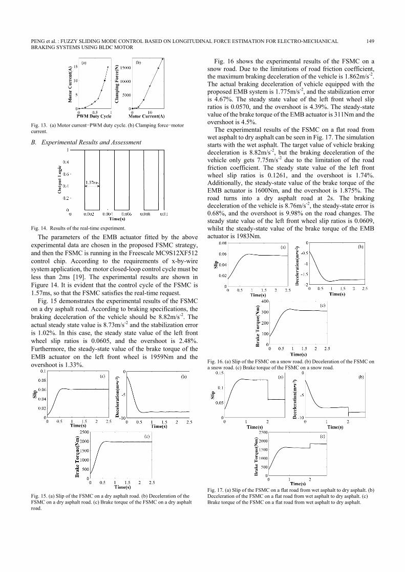
Fig. 16 shows the experimental results of the FSMC on a snow road. Due to the limitations of road friction coefficient, the maximum braking deceleration of the vehicle is 1.862m/s-2. The actual braking deceleration of vehicle equipped with the proposed EMB system is 1.775m/s-2, and the stabilization error is 4.67%. The steady state value of the left front wheel slip ratios is 0.0570, and the overshoot is 4.39%. The steady-state value of the brake torque of the EMB actuator is 311Nm and the overshoot is 4.5%.
The experimental results of the FSMC on a flat road from wet asphalt to dry asphalt can be seen in Fig. 17. The simulation starts with the wet asphalt. The target value of vehicle braking deceleration is 8.82m/s-2, but the braking deceleration of the vehicle only gets 7.75m/s-2 due to the limitation of the road friction coefficient. The steady state value of the left front wheel slip ratios is 0.1261, and the overshoot is 1.74%. Additionally, the steady-state value of the brake torque of the EMB actuator is 1600Nm, and the overshoot is 1.875%. The road turns into a dry asphalt road at 2s. The braking deceleration of the vehicle is 8.76m/s-2, the steady-state error is 0.68%, and the overshoot is 9.98% on the road changes. The steady state value of the left front wheel slip ratios is 0.0609, whilst the steady-state value of the brake torque of the EMB actuator is 1983Nm.
Fig. 16. (a) Slip of the FSMC on a snow road. (b) Deceleration of the FSMC on a snow road. (c) Brake torque of the FSMC on a snow road.
Fig. 17. (a) Slip of the FSMC on a flat road from wet asphalt to dry asphalt. (b) Deceleration of the FSMC on a flat road from wet asphalt to dry asphalt. (c) Brake torque of the FSMC on a flat road from wet asphalt to dry asphalt.
150 CES TRANSACTIONS ON ELECTRICAL MACHINES AND SYSTEMS, VOL. 2, NO. 1, MARCH 2018
VII. CONCLUSION In view of the fact that the quarter-vehicle model ignores the
front and rear axle load transfer, a half-vehicle dynamic model is established in this paper. A FSMC strategy based on wheel slip ratio for the EMB system is proposed accordingly. By virtue of this strategy, the front and rear axle load transfer, the normal and emergency braking conditions are both accounted for. The results of numerical simulations indicate that the proposed strategy has the superior control performance, stronger robustness, better adaptability to different roads, and shorter braking distance, in comparison with PID and SMC. Moreover, the results of the hardware-in-loop test further illustrate the effectiveness of the proposed strategy.
In the future, there are still many measures to improve the control algorithm and improve the control performance of the EMB system, especially the formulation of fuzzy rules, the improvement of membership functions, etc.
REFERENCES [1] Zhang L, Li L, Lin C, et al. “Coaxial-coupling traction control for a
four-wheel-independent-drive electric vehicle on a complex road”. Proceedings of the Institution of Mechanical Engineers Part D Journal of Automobile Engineering, vol. 228, no. 12, pp. 1398-1414, 2014.
[2] Zhang L, Yu L, Wang Z, et al. “All-Wheel braking force allocation during braking-in-turn maneuver for vehicle with brake-by-wire system considering braking efficiency and stability”. IEEE Transactions on Vehicular Technology. 2015; DOI. 10.1109/TVT.2015.2473162.
[3] Kuktae K, Li Q, Chanmin P, et al. “A design of intelligent actuator logic using fuzzy control for EMB system”. Lecture Notes in Engineering & Computer Science, vol. 2189, no. 1, pp. 978-983, 2011.
[4] Li D, Zhang L, He B. “Fuzzy control based on vehicle slip-ratio for electro-mechanical braking systems”. Journal of Mechanical Engineers, vol. 48, no. 20, pp. 121-126, 2012.
[5] Wang Z, Yu L, Song J. “The status quo of research on vehicle wheel slip control based on brake system”. Automotive Engineering. vol. 36, no. 1, pp. 81-87, 2014.
[6] Cho W, Yoon J, Yim S, et al. “Estimation of Tire Forces for Application to Vehicle Stability Control”. IEEE Transactions on Vehicular Technology, vol. 59, no. 2, pp. 638-649, 2010.
[7] Ray L R. “Nonlinear Tire Force Estimation and Road Friction Identification: Simulation and Experiments”. Automatica, vol. 33, no. 10, pp. 1819-1833.
[8] Johansen T, Petersen I, Kalkkuhl J, et al. “Gain-scheduled wheel slip control in automotive brake systems. Control Systems Technology”. IEEE Transactions on. vol. 11, no. 6, pp. 799-811, 2013.
[9] Solyom S, Rantzer A, Lüdemann J. “Synthesis of a model-based tire slip controller”. Vehicle System Dynamics, vol. 41, no. 6, pp. 475-499, 2004.
[10] Choi S B. “Antilock brake system with a continuous wheel slip control to maximize the braking performance and the ride quality. Control Systems Technology”, IEEE Transactions on, vol. 16, no. 5, pp. 996-1003, 2008.
[11] Dousti M, Baslamisli S C, Onder E T, et al. “Design of a multiple-model switching controller for abs braking dynamics”, Transactions of the Institute of Measurement & Control, vol. 37, no. 5, pp. 582-595, 2015.
[12] De Castro R, Araújo R E, Tanelli M, et al. “Torque blending and wheel slip control in EVs with in-wheel motors”, Vehicle System Dynamics. vol. 50, no. sup1, pp. 71-94, 2012.
[13] Fanbiao Li, Chenglong Du,Chunhua Yang, et al. “ Passivity-based Asynchronous Sliding Mode Control for Delayed Singular Markovian Jump Systems”. IEEE TRANSACTIONS ON AUTOMATIC CONTROL.2017, DOI: 10.1109/TAC.2017.2776747.
[14] Fanbiao Li, Ligang Wu, Peng Shi. et al. “State estimation and sliding mode control for semi-Markovian jump systems with mismatched uncertainties”. Automatica, vol. 51, pp. 385–393, 2015.
[15] Liu J, Sun F. “Research and development on theory and algorithms of sliding mode control”. Control Theory & Applications, vol. 24, no. 3, pp. 407-418, 2007.
[16] Tanelli M, Sartori R, Savaresi S M. “Combining slip and deceleration control for brake-by-wire control systems: a sliding-mode approach”. European Journal of Control, vol. 13, no. 6, pp. 593-611, 2007.
[17] Peng X, Chen C, Zhang J. “Study of sliding mode control for electromechanical brake systems”, Journal of Hunan University (Natural Sciences), vol. 37, no. 8, pp. 35-39, 2010.
[18] Jie Tao, Renquan Lu, Peng Shi.et al. “Dissipativity-based Reliable Control for Fuzzy Markov Jump Systems with Actuator Faults”. IEEE Transactions on Cybernetics, vol. 47, no. 9, pp. 2377-2388, 2017.
[19] Jie Tao, Renquan Lu, Hongye Su, et al. “Asynchronous Filtering of Nonlinear Markov Jump Systems with Randomly Occurred Quantization via T-S Fuzzy Models”. IEEE Transactions on Fuzzy Systems, DOI: 10.1109/TFUZZ.2017.2754999.
[20] Burckhardt M. Fahrwerktechnik, radschlupf regelsysteme. Vogel Verlag; pp. 39-45, 1993.
[21] Kiencke U, Nielsen L. Vehicle modelling. Springer Berlin Heidelberg, pp. 301-349, 2005.
[22] Jo C, Hwang S, Kim H. “Clamping-force control for electromechanical brake. Vehicular Technology”, IEEE Transactions on, vol. 59, no. 7, pp. 3205-3212, 2010.
[23] Reif K, Sonnemann F, Unbehauen R. “An EKF-based nonlinear observer with a prescribed degree of stability”, Automatica, vol. 34, no. 9, pp. 1119-1123, 1998.
[24] Peng X, Zhang J, Chen C. “Calculation of RBF neural network based optimal slip ratio”. Journal of Mechanical Engineers, vol. 47, no. 14, pp. 108-113, 2011.
[25] Heiner G, Thurner T. “Time-triggered architecture for safety-related distributed real-time systems in transportation systems”. Twenty-Eighth Annual International Symposium on Fault-Tolerant Computing; Munich; Germany, pp. 402-407, 1998.
Xiaoyan Peng received the B.S. and M.S. degrees in mechanical engineering and Ph.D. degree in automatic control from Hunan University, Changsha, China, in 1986, 1989, and 2013, respectively. She is currently a Professor at the College of Mechanical and Vehicle Engineering, Hunan University. Her research interests cover control of mechatronic systems and
safety analysis of autonomous vehicles.
Mingfei Jia was born in Henan, China in 1991. He received the B.S. degree in Vehicle engineering from Wuhan University of Technology, Wuhan, China, in 2015. He is currently pursuing the Master degree in Mechanical engineering from Hunan University, Changsha, China. The main research area is Automotive
Electronic Control Technology and Advanced Driver Assistant Systems.
PENG et al. : FUZZY SLIDING MODE CONTROL BASED ON LONGITUDINAL FORCE ESTIMATION FOR ELECTRO-MECHANICAL 151 BRAKING SYSTEMS USING BLDC MOTOR
Lei He was born in Changsha, China in 1991. He received the B.S. and M.S. degree in Mechanical engineering and Mechanical electronic engineering from Hunan University, Changsha, China, in 2013 and 2016, respectively. He is currently working on the automatic driving department at Geely automobile r&d
center.
Xiang Yu received the B.S., M.S., and Ph.D. degrees from Northwestern Polytechnical University, Xi’an, China, in 2003, 2004, and 2008, respectively. From 2009 to 2013, he was a postdoctoral research fellow at The University of Western Ontario, London, ON, Canada. He is currently working at Concordia University. His main research interests
include GNC for aerospace engineering systems, and fault-tolerant control design.
Yibin Lv was born in Guangxi, China in 1989. He received the B.S. and M.S. degree in Mechanical engineering and Mechanical electronic engineering from Hunan University, Changsha, China, in 2013 and 2016, respectively. The main research area is the brake by wire system of braking force distribution.


![Robust Fuzzy-Second Order Sliding Mode based …thesai.org/...Robust_Fuzzy_Second_Order_Sliding_Mode_based...Con… · Robust Fuzzy-Second Order Sliding Mode based ... [3]. Sliding-mode](https://static.documents.pub/doc/80x56/5b7a16407f8b9a483c8b5dce/robust-fuzzy-second-order-sliding-mode-based-robust-fuzzy-second-order-sliding.jpg)


