Page 1
Dr. Nagaraj Sitaram, Principal & Professor, Amrutha Institute of Engineering &
Management, Bidadi, Ramanagar District, Karnataka
15 CV 33 FLUID MECHANICS NOTES
MODULE-2
Module-2A : Hydrostatic forces on Surfaces
Module-2B :Fundamentals of fluid flow (Kinematics)
by
Dr. Nagaraj Sitaram, Principal & Professor, Amrutha Institute of Engineering &
Management, Bidadi, Ramanagar District, Karnataka State
Module-2A: Hydrostatic forces on Surfaces
Definition, Total pressure, centre of pressure, total pressure on horizontal, vertical and inclined
plane surface, total pressure on curved surfaces, water pressure on gravity dams, Lock gates.
Numerical Problems.
2.0 Definitions
Pressure or Pressure intensity (p): It is the Fluid pressure force per unit area of
application. Mathematically, A
pP . Units are Pascal or N/m
2.
Total Pressure (P): This is that force exerted by the fluid on the contact surface
(of the submerged surfaces), when the fluid comes in contact with the surface
always acting normal to the contact surface. Units are N.
Centre of Pressure: It is defined as the point of application of the total pressure
on the contact surface.
The submerged surface may be either plane or curved. In case of plane surface,
it may be vertical, horizontal or inclined. Hence, the above four cases may be
studied for obtaining the total pressure and centre of pressure.
Page 2
Dr. Nagaraj Sitaram, Principal & Professor, Amrutha Institute of Engineering &
Management, Bidadi, Ramanagar District, Karnataka
2.1 Hydrostatic Forces on Plane Horizontal Surfaces:
If a plane surface immersed in a fluid is horizontal, then
Hydrostatic pressure is uniform over the entire surface.
The resultant force acts at the centroid of the plane.
Consider a horizontal surface immersed in a static fluid as shown in Fig. As all
the points on the plane are at equal depth from the free surface of the liquid, the
pressure intensity will be equal on the entire surface and given by p = g y ,
where y is the depth of the fluid surface
Let A = Area of the immersed surface
The total pressure force acting on the immersed surface is P
P = p x Area of the surface = g y A
P = gA y
Where y is the centroidal distance immersed surface from the free surface of
the liquid and h is the centre of pressure.
F
G
P
Page 3
Dr. Nagaraj Sitaram, Principal & Professor, Amrutha Institute of Engineering &
Management, Bidadi, Ramanagar District, Karnataka
2.2 Hydrostatic Forces on Vertical Plane Surface:
Vertical Plane surface submerged in liquid
Consider a vertical plane surface of some arbitrary shape immersed in a liquid of mass density
as shown in Figure below:
End View Elevation
Let, A = Total area of the surface
h = Depth of Centroid of the surface from the free surface
G = Centroid of the immersed surface
C = Centre of pressure
..PCh = Depth of centre of pressure
Consider a rectangular strip of breadth b and depth dy at a depth y from the free surface.
Total Pressure:
The pressure intensity at a depth y acting on the strip is p = gh
Total pressure force on the strip = dP = (gh)dA
The Total pressure force on the entire area is given by integrating the above expression over
the entire area P = dP = (gh)dA= g h dA Eq.(1)
But y dA is the Moment of the entire area about the free surface of the liquid given by
∫ hAhdA =
Substituting in Eq.(1), we get hAγhgAρP == Eq.(2)
Where is the specific weight of Water
For water, =1000 kg/m3 and g = 9.81 m/s
2. The force will be expressed in Newtons (N)
G C
P
h
y
dh
b
Page 4
Dr. Nagaraj Sitaram, Principal & Professor, Amrutha Institute of Engineering &
Management, Bidadi, Ramanagar District, Karnataka
2.3 Hydrostatic Force on a Inclined submerged surface:
The other important utility of the hydrostatic equation is in the determination of force
acting upon submerged bodies. Among the innumerable applications of this is the force
calculation in storage tanks, ships, dams etc.
First
consi
der a
plana
r
arbitr
ary
shap
e
submerged in a liquid as shown in the figure. The plane makes an angle with the liquid
surface, which is a free surface. The depth of water over the plane varies linearly. This
configuration is efficiently handled by prescribing a coordinate frame such that the y-axis is
aligned with the submerged plane. Consider an infinitesimally small area at a (x,y). Let this small
area be located at a depth from the free surface.dA = dx.dy
Differential Force acting on the differential area dA of plane,
)()()Area()Pressure( dAhdF (Perpendicular to plane)
Then, Magnitude of total resultant force FR
Figure 3.4 :Force upon a submerged object
Page 5
Dr. Nagaraj Sitaram, Principal & Professor, Amrutha Institute of Engineering &
Management, Bidadi, Ramanagar District, Karnataka
A AR dAyhdAF sin
Where sinyh
sin A ydA
AyydA cA
whereyc: y coordinate of the center of area (Centroid)
c.f.Centeror 1st moment
M
CMXxdm
&
M
CMYydm
(XC & YC: Center of Mass)
A xdA= xc &
A ydA = yc (xc&yc: Center of Area)
Moment of inertia or 2nd moment
M
Idmr2
(2nd moment of Mass)
xAIdAy
2
& yA
IdAx 2
(2nd moment of Area)
Then,
AhγθAyγF ccR ) (sin ==
Where ch : Pressure at the centroid = (Pressure at the centroid) Area
- Magnitude of a force on an INCLINED plane
- Dependent on
Area, and Depth of centroid
- Perpendicular to the surface (Direction)
i) Position of FR on y-axis ‘yR’ : y coordinate of the point of action of FR
Moment about x axis:
ARcRR ydFyAyyF )sin(
AAdAydAy 22 sinsin
1st moment of the area
- Related with the center of area
Page 6
Dr. Nagaraj Sitaram, Principal & Professor, Amrutha Institute of Engineering &
Management, Bidadi, Ramanagar District, Karnataka
Ah
dAhh
c
A
R
∫2
= =Ah
I
c
x where Ax dAyI 2
:2nd
moment of area
or, by using the parallel-axis theorem,
2cxcx AyII
hA
θSinIhh
G
PC
2
+=..
(The centre of pressure below the centroid)
Solved Examples:
Q1. A rectangular tank 10 m x 5 m and 3.25 m deep is divided by a partition
wall parallel to the shorter wall of the tank. One of the compartments contains
water to a depth of 3.25 m and the other oil of specific gravity 0.85 to a depth
of 2 m. Find the resul tant pressure on the partition.
Solution:
The problem can be solved by considering hydrostatic pressure distribution
diagram for both water and oil as shown in Fig.
From hydrostatic law, the pressure intensity p at any depth ywis given by
p = So g yw
where is the mass density of the liquid
Pressure force P = p x Area
Pw = 1000 x 10 x 3.25 x 5 x 3.25 = 528.125 kN ()
So=0.85
yo = 2 m
g So yo
S= 1.00
yw = 3.25 m
g Syw
yw/3 yo/3
Pw Po
Page 7
Dr. Nagaraj Sitaram, Principal & Professor, Amrutha Institute of Engineering &
Management, Bidadi, Ramanagar District, Karnataka
B
C
G
2.0 m
1.0 m y = 2 m
Acting at 3.25/3 m from the base
Po = 0.85 x 1000 x 10 x 2.0 x 5 x 2.0 = 200 kN ()
Acting at 2/3 m from the base.
Net Force P = Pw – Po = 528.125 – 200.0 = 328.125 kN ()
Location:
Let P act at a distance y from the base. Taking moments of Pw ,Po and P about
the base, we get
P x y = Pwx yw /3 – Pox yo /3
328.125 y = 528.125 x (3.25/3) – 200 x (2/3) or y = 1.337 m.
Q2 . Determine the total force and location of centre of pressure for a circular
plate of 2 m dia immersed vertically in water with its top edge 1.0 m below the
water surface
Solution:
A = m142.34
2
4
22
D
Assume
= 1000 kg/m3 and g = 10 m/s
2
We know that the total pressure force is given by
P = SogA y = 1000 x 10 x 3.142 x 2 = 62.83 kN
Centre of Pressure
The Centre of pressure is given by
yA
Iyh
g
444
m785.04
1
4
R
I g
m125.22142.3
785.02
h
Page 8
Dr. Nagaraj Sitaram, Principal & Professor, Amrutha Institute of Engineering &
Management, Bidadi, Ramanagar District, Karnataka
Q.3 A large tank of sea water has a door in the side 1 m square. The top of the door is 5 m
below the free surface. The door is hinged on the bottom edge. Calculate the force required at
the top to keep it closed. The density of the sea water is 1033 kg/m3.
Solution: The total hydrostatic force cwatersea hAγF =
373101338191033 mNxγ watersea /.. ==
Given A = 1m X 1m = 1m2
mh c 552
15 .=+=
N5.55735=5.5X1X73.10133=F
Acting at centre of pressure (yc.p):
From the above hc = 5.5m, A = 1m2
( ) 4
33
xxc m08333.0=12
1X1=
12
BD=I
( )
mXAh
Ihh
c
xxc
cPC 5155551
08333055 .
.
.... =+=+=
Distance of Hydrostatic force (F) from the bottom of the hinge = 6-5.515 = 0.48485m
The force ‘P’ required at the top of gate (1m from the hinge)
kN023.27=N4.27023=P
48485.0X5.55735=48485.0FX=1PX
Q.4 Calculate the total hydrostatic force and location of centre of pressure for a circular plate of
2.5 m diameter immersed vertically in water with its top edge 1.5 m below the oil surface (Sp.
Gr.=0.9)
Solution:
A = 2m.9144
2
4
22
=×
=× πDπ
Assume
= 0.9X1000=900 kg/m3,g=9.8 m/s
2
38829819900 mNXγoil /. ==
B
C
G
2.5 m
1.5 m y = 2.75m
m
C
Page 9
Dr. Nagaraj Sitaram, Principal & Professor, Amrutha Institute of Engineering &
Management, Bidadi, Ramanagar District, Karnataka
S= 1.00
yw = 1.5 m
g Syw
yw/3
Pw
hc = 2.75m
We know that the total pressure force is given by ‘F’
F = o i l A hc= 8829 x 4.91 x 2.75 = 238184 N = 238.184 kN
Centre of Pressure:
The Centre of pressure is given by
( )
c
xxc
cPC Ah
Ihh +=..
4m..
917514
251
4
44
=×
==πRπ
Ig
m...
.... 8922
752914
91751752 =
×+=PCh
Q.5 A square tank with 2 m sides and 1.5 m high contains water to a depth of 1
m and a liquid of specific gravity 0.8 on
the water to a depth of 0.5 m. Find the
magnitude and location of hydrostatic
pressure on one face of tank.
Solution:
The problem can be solved by
considering hydrostatic pressure
distribution diagram for water as shown
in Fig. From hydrostatic law, the
pressure intensity p at any depth ywis given by p = So g yw
where is the mass density of the liquid
Pressure force P = p x Area
Pw = 1000 x 10 x 2.0 x 1.5 x 1.5 = 45 kN ()
cting at 1.5/3=0.5 m from the base
Page 10
Dr. Nagaraj Sitaram, Principal & Professor, Amrutha Institute of Engineering &
Management, Bidadi, Ramanagar District, Karnataka
Q.6 A trapezoidal channel 2m wide at the bottom and 1m deep has side slopes 1:1. Determine: i)
Total pressure ii) Centre of pressure, when it is full of water
Ans: Given B = 2m Area of flow A = (B+sy)y = 3m2
The combined centroid will be located based on two triangular areas and one rectangle
(shown as G1, G2, G2)
321
332211
AAA
hAhAhAy
The total area A = 3m2
Area of rectangle = 2 ×1 = 2m2
Area of Triangle = ×1×1=0.5m2
i) The total pressure P = w×A× = 9810×3×0.444 = 13080N
ii) Centre of pressure
The centroidal moment of Inertia of Rectangle and Triangle is
The moment of Inertia about combined centroid can be obtained by using parallel axis theorem
(as both the triangles are similar)
Substituting in Eq.1, The centre of pressure from free surface of water
2
1
my 44409
4
3
3330112
1333011
2
15012
.
.)(.)(.)(
y
surfacewaterfrommatmI
surfacewaterfrommatmI
G
G
3330028036
11
501667012
12
43
1
43
1
..
..
1.EqyA
Iyh
g
2
222
2
222
2
111 dAIdAIdAII GGGG
2
222200618016670 dAII GG ..
424080006200280200618016670 mIG .....
mh
EqyA
Iyh
g
6252044403
240804440
1
..
..
.
Page 11
Dr. Nagaraj Sitaram, Principal & Professor, Amrutha Institute of Engineering &
Management, Bidadi, Ramanagar District, Karnataka
60°
1.2m h
x
xp
a
CG
CP
1.5m
3.0m
Q.7. A rectangular plate 1.5m x 3.0m is submerged in water and makes an angle of 60° with the
horizontal, the 1.5m sides being horizontal. Calculate the magnitude of the force on the plate and
the location of the point of application of the force, with reference to the top edge of the plate,
when the top edge of the plate is 1.2m below the water surface.
Solution:
mh 88625138615160
21....
sin
.=+=+
°=
A = 3m X 1.5m = 4.5m2
myh 499260886260 .sin.sin =°=°=
51349928191000AhgF ...
kN92109N1092109F 3 ..
hA
SinIhh
G
PC
602
+=..
mh PC 146.3260.0886.2886.212
3886.2∴
2
..
From the top edge of the plate, m760138611463a ...
Q.8 A vertical bulkhead 4m wide divides a storage tank. On one side of the bulkhead petrol
(S.G. = 0.78) is stored to a depth of 2.1m and on the other side water is stored to a depth of 1.2m.
Determine the resultant force on the bulkhead and the position where it acts.
Solution:
bghbh2
hgAhgF 2
21
kN567N412819780F 2
21
1 ...
kN2528N4218191000F 2
21
2 ...
Hence the resultant force
kN25392528567FFF 21R ...
Petrol
2.1m
FF1
x1 x2
F2 xR
1.2m
Wate
r
Width = 4m
O
Page 12
Dr. Nagaraj Sitaram, Principal & Professor, Amrutha Institute of Engineering &
Management, Bidadi, Ramanagar District, Karnataka
( ) hhh
hbh
bhh
hA
Ihh
G
PC 32
3
622
1
122=+=+=+=..
From the diagram, y = h – 2/3h =
1/3h
Hence, y1 = 2.1 / 3 = 0.7m and y2 = 1.2 / 3 = 0.4m
Taking moments about ‘O’, FR•yR = F1• y1 – F2• y2
i.e. 39.25 × yR = 67.5 × 0.7 – 28.25 × 0.4 and hence yR = 0.916m
Q.9 A hinged, circular gate 750mm in diameter is used to close the opening in a sloping side of a
tank, as shown in the diagram in Error! Reference source not found.. The gate is kept closed
against water pressure partly by its own weight and partly by a weight on the lever arm. Find the
mass M required to allow the gate to begin to open when the water level is 500mm above the top
of the gate. The mass of the gate is 60 kg. (Neglect the weight of the lever arm.)
Solution:
mm70745
500a
sin
mm1082375ax
mm76545xh sin
475076508191000AhgF 2...
kN3153N103153F 3 ..
x16
dx
xd
4
64
dx
xA
Ixx
2
2
4G
P
m114103200821082116
7500821x
2
P ....
..
Taking moments about the hinge
453750mg80MgaxF P cos..
4537506080M819707011413315 cos.....
45375060
819
70701141331580M cos.
.
...
M × 0.8 5.121165.137
kg15280
5121M
.
.
0.8m
0.375 cos 45°
Hinge
45° mg
mg
0.375m
yp-a F
F
800mHing
e
500m
m
Mg
m
750mm
Page 13
Dr. Nagaraj Sitaram, Principal & Professor, Amrutha Institute of Engineering &
Management, Bidadi, Ramanagar District, Karnataka
Q.10. A rectangular plate 1 m x 3 m is immersed in water such that its upper and
lower edge is at depths 1.5 m and 3 m respectively. Determine the total pressure
acting on the plate and locate it .
Solution:
A = 1 x 3 = 3 m2
w = 9810 N/m3
mmm
h c 2522
513.
.=
+=
We know that the total pressure force is given by
F = wa te r Ahc= 9810 x 3.0 x 2.25 = 66217.5 N
Sin = 1.5 / 3 = 0.5
= 30o
Centre of Pressure; The Centre of pressure is given by
( ) 4
33
25212
31
12m
dbI
xxC .=×
==
hc= 2.25m
( )
c
xxc
cPC Ah
θSinIhhCC
2
1 +== ..
mhCC
X
SinhCC
PC
PC
33333.2
25.23
3025.225.2
..1
2
..1
3m
3 m
1.5 m
B
A
CP
G
1m
C1 G1
A1
Page 14
Dr. Nagaraj Sitaram, Principal & Professor, Amrutha Institute of Engineering &
Management, Bidadi, Ramanagar District, Karnataka
Q 11. A circular plate 2.5m diameter is immersed in water, its greatest and least depth below the
free surface being 3m and 1m respectively. Find
(i) The total pressure on one face of the plate and (ii) Position of centre of pressure
Ans: Given d = 2.5m,
F = wA = 9.81×4.909×2 = 96.31 kN
Q.12. A 2m wide and 3m deep rectangular plane surface lies in water in such a way the top of
and bottom edges are at a distance of 1.5m and 3m respectively from the surface. Determine the
hydrostatic force and centre of pressure
Ans: Given A = 3m × 2m = 6m2,
43
5.412
32mIG
Hydrostatic force
P = 132.435 kN
13.53
5.2
21
Sin
mh 211
222 909.45.244
mdA
444 917.15.26464
mdIG
h
mh
Sin
hA
SinIhh
pc
G
pc
1252
29094
135391712
22
.
.
..
..
..
2
5.13681.9P
hAP w
30
5.03
5.10.3sin
Page 15
Dr. Nagaraj Sitaram, Principal & Professor, Amrutha Institute of Engineering &
Management, Bidadi, Ramanagar District, Karnataka
The centre of pressure
Q.13 A rectangular plate 2 m x 3 m is immersed in oil of specific gravity 0.85
such that its ends are at depths 1.5 m and 3 m respectively. Determine the total
pressure acting on the plate and locate it .
Solution:
A = 2 x 3 = 6 m2
So = 0.85
Assume
= 1000 kg/m3
g = 10 m/s2
y = GG1
h = CC1
Sin = 1.5 / 3 = 0.5
= 30o
GG1 = G1A1 + A1G = G1A1 + AG Sin
GG1 = 1.5 + (3/2) Sin 30 = 2.25 m
We know that the total pressure force is given by
P = SogA y = 0.85 x 1000 x 10 x 6 x 2.25 = 114.75 kN
Centre of Pressure
The Centre of pressure is given by
yA
Iyh
g sin
2
mh
hA
SinIhh
PC
GPC
33.225.26
415.4
25.2.
2
.
3 m
1.5 m
B
A
C
G
2 m
C1 G1
A1
Page 16
Dr. Nagaraj Sitaram, Principal & Professor, Amrutha Institute of Engineering &
Management, Bidadi, Ramanagar District, Karnataka
433
5.412
32
12m
dbI g
mh 33.230sin25.26
5.425.2 2
Q.14. A Circular plate with a concentric hole is immersed in water in such a
way that its greatest and least depth below water surface are 4 m and 1.5 m
respectively. Determine the total pressure on the plate and locate it if the
diameter of the plate and hole are 3 m and 1.5 m respectively.
Solution:
Assume
= 1000 kg/m3 and g = 10 m/s
2
22222 m3014.55.1344
dDA
y = GG1
h = CC1
Sin = 2.5 / 3 = 0.833 and = 30o
GG1 = G1A1 + A1G = G1A1 + AG Sin
GG1 = 1.5 + (3/2) 0.833 = 2.75 m
We know that the total pressure force is given by
P = SogA y = 1000 x 10 x5.3014 x 2.75 = 144.7885 kN
Centre of Pressure
The Centre of pressure is given by
yA
Iyh
g sin
2
44444 m728.375.05.144
rRI g
m814.230sin75.23014.5
728.375.2 2
h
Page 17
Dr. Nagaraj Sitaram, Principal & Professor, Amrutha Institute of Engineering &
Management, Bidadi, Ramanagar District, Karnataka
Q.15 . A circular plate of dia 1.5 m is immersed in a liquid of relative density of
0.8 with its plane making an angle of 30o with the horizontal. The centre of the
plate is at a depth of 1.5 m below the free surface. Calculate the total force on
one side of the plate and location of centre of pressure.
Solution:
Assume
= 1000 kg/m3 and g = 10 m/s
2
So = 0.80
222
m1.7674
5.1
4
D
A
y = GG1
h = CC1
= 30o
GG1 = G1A1 + A1G = G1A1 + AG Sin
GG1 = 1.5 + (3/2) 0.833 = 2.75 m
We know that the total pressure force is given by
P = SogA y = 0.8 x 1000 x 10 x 1.767 x 2.75 = 38.874 kN
Centre of Pressure
The Centre of pressure is given by
yA
Iyh
g sin
2
444
m2485.04
75.0
4
R
I g
m763.230sin75.2767.1
2485.075.2 2
h
Page 18
Dr. Nagaraj Sitaram, Principal & Professor, Amrutha Institute of Engineering &
Management, Bidadi, Ramanagar District, Karnataka
Q.16 A vertical gate closes a circular tunnel of 5 m diameter running full of
water, the pressure at the bottom of the gate is 0.5 MPa. Determine the
hydrostatic force and the position of centre of pressure.
Solution:Assume = 1000 kg/m3 and g = 10 m/s
2
Pressure intensity at the bottom of the gate is = p =Sogy
Where y is the depth of point from the free surface.
0.5 x 106 = 1000 x 10 x y
y = 50 m
Hence the free surface of water is at 50 m from the bottom of the gate
222
m.635194
5
4
D
A
y = OG= 50 - 2.5 = 47.5 m
We know that the total pressure force is given by
P = SogA y = 1000 x 10 x 19.635 x 47.5 =9326.625 kN
Centre of Pressure
The Centre of pressure is given by
yA
Iyh
g
444
m68.304
5.2
4
R
I g
m533.475.47635.19
68.305.47
h
i .e. 50.0 – 47.533 = 2.677 m from the bottom of the gate or tunnel.
5 m
50 m
G
O
Page 19
Dr. Nagaraj Sitaram, Principal & Professor, Amrutha Institute of Engineering &
Management, Bidadi, Ramanagar District, Karnataka
Page 20
Dr. Nagaraj Sitaram, Principal & Professor, Amrutha Institute of Engineering &
Management, Bidadi, Ramanagar District, Karnataka
2.4 Hydrostatic Forces on Curved Surfaces
Since this class of surface is curved, the direction
of the force is different at each location on the
surface. Therefore, we will evaluate the x and y
components of net hydrostatic force separately.
Consider curved surface, a-b. Force balances
in x & y directions yield
Fh = FH
Fv = Wair +W1 + W2
From this force balance, the basic rules for determining the horizontal and vertical component of
forces on a curved surface in a static fluid can be summarized as follows:
Horizontal Component, Fh
The horizontal component of force on a curved surface equals the force on the plane area formed
by the projection of the curved surface onto a vertical plane normal to the component.
The horizontal force will act through the c.p.
(not the centroid) of the projected area.
from the Diagram:
All elements of the analysis are performed with the
vertical plane. The original curved surface is
important only as it is used to define the projected
vertical plane.
a
b
a
cp
hcg
Fh
ycp
a’
b’
Projected verticalplane
Curvedsurface
Page 21
Dr. Nagaraj Sitaram, Principal & Professor, Amrutha Institute of Engineering &
Management, Bidadi, Ramanagar District, Karnataka
Therefore, to determine the horizontal component of force on a curved surface in a hydrostatic
fluid:
Vertical Component - Fv
The vertical component of force on a curved surface equals the weight of the effective column of
fluid necessary to cause the pressure on the surface.
The use of the words effective column of fluid is important in that there may not always actually
be fluid directly above the surface. (See graphics below)
This effective column of fluid is specified by identifying the column of fluid that would be
required to cause the pressure at each location on the surface.
Thus, to identify the Effective Volume - Veff:
Fv = Veff
Fluid above the surface
No fluid actually above surface
a
b
aVeff P
PP
a
a
b
Veff
P
P P
fluid
x
y
yxF
FFFR 122 tan
Page 22
Dr. Nagaraj Sitaram, Principal & Professor, Amrutha Institute of Engineering &
Management, Bidadi, Ramanagar District, Karnataka
Q.17 Find the horizontal and vertical component of force and its point of
application due to water per meter length of the gate AB having a quadrant
shape of radius 2.5 m shown in Fig. Find also the resultant force in magnitude
and direction.
Solution:
Assume
= 1000 kg/m3 and g = 9.81 m/s
2
R = 2.5 m, Width of gate = 1 m
Horizontal force Fx
Fh = Force on the projected area of the
curved surface on the vertical plane
= Force on BC
A = 2.5 x 1 = 2.5m2
m 25.1=2
5.2=y
F = wa te r Ahc= 9810 x 2.5 x 1.25 = 30656 N = 30.656kN
This will act at a distance m 3
5=5.2×
3
2=h from the free surface of liquid AC
Vertical Force F y
Fy= Weight of water (imaginary) supported by AB
= wa te r x Area of ACBx Length of gate
= 9810 x4
5.2×π 2
x1= 48154N=48.154kN
This will act at a distance m061.1=π3
5.2×4=x from CB
The Resultant force
084.57=154.48+656.30=F+F=F 222y
2x kNand its
inclination is given by
o1
x
y1 51.57=656.30
154.48tan=
F
Ftan=α
A
B
C
R=2.5m
Fx
Fy
F
Page 23
Dr. Nagaraj Sitaram, Principal & Professor, Amrutha Institute of Engineering &
Management, Bidadi, Ramanagar District, Karnataka
Q.18 Find the horizontal and vertical component of force and its point of
application due to water per meter length of the gate AB having a quadrant
shape of radius 2m shown in Fig. Find also the resultant force in magnitude and
direction.
Solution:
Assume
= 1000 kg/m3 and g = 10 m/s
2
R = 2 m, Width of gate = 1 m
Horizontal force Fx
Fx = Force on the projected area of the curved
surface on the vertical plane
= Force on BO = P = SogA y
A = 2 x 1 = 2 m2
m 12
2y
Fx= 1000 x 10 x 2 x 1 = 20 kN
This will act at a distance m 3
42
3
2h from the free surface of liquid
Vertical Force F y
Fy= Weight of water (imaginary) supported by AB
= Sog x Area of AOBx Length of gate
= 1000 x 10 x 4
22 x1= 31.416 kN
This will act at a distance m 848.03
24
x from OB
Resultant force 25.37426.3120 2222 yx FFF
kNand its inclination is given by
o
x
y
F
F527.57
20
426.31tantan 11
A
B
O
R=2m
Fx
Fy
F
Page 24
Dr. Nagaraj Sitaram, Principal & Professor, Amrutha Institute of Engineering &
Management, Bidadi, Ramanagar District, Karnataka
Q.19. A cylinder holds water in a channel as shown in Fig. Determine the
weight of 1 m length of the cylinder.
Solution:
Radius of Cylinder = R = 2m
Length of cylinder = 1 m
Weight of Cylinder = W
Horizontal force exerted by water= Fx
Fx = Force on vertical area BOC
= SogA y = 1000 x 10 x (4x 1)x (2/2) = 40 kN ()
The vertical force exerted by water=Fy =Weight of water enclosed in BDCOB
Fy = Sog
4
22xL=1000x10x3 .142=31.416kN ()
For equilibrium of the cylinder the weight of the cylinder must be equal to the
force exerted by the water on the cylinder. Hence, the weight of the cylinder is
31 .416 kN per meter length .
Q.20. Fig. shows the cross section of a tank full of water under pressure. The
length of the tank is 2 m. An empty cylinder lies along the length of the tank on
one of its corner as shown. Find the resultant force acting on the curved surface
of the cylinder.
Solution:
R=1 m
L = 2 m
p = gh = 1000 x 10x h = 20x 103
h = 2 m
For this pressure, the free surface should be 2 m
above A
Water in a
channel
Radius of
cylinder=2 m
C
O
B
D A
Fx
Fy
W
20kPa
1.5m
A
B
C
R=1m
Page 25
Dr. Nagaraj Sitaram, Principal & Professor, Amrutha Institute of Engineering &
Management, Bidadi, Ramanagar District, Karnataka
Horizontal component of force F x
Fx = SogA y
A = 1.5x 2.0 = 3 m2
m 75.22
5.12 y
Fx = 1000 x 10 x 3.0x 2.75 = 82.5 kN ()
The vertical force exerted by water = Fy
Fy = Weight of water enclosed in ABC
= Weight of water enclosed in CODEABC
= Weight of water enclosed in (CODFBC – AEFB)
But Weight of water enclosed in CODFBC
= Weight of water enclosed in (COB+ODFBO)
= kN 708.6525.214
11010002
4
22
ODBO
Rg
Weight of water inAEFB = Sog[Area of AEFB]x 2.0
= Sog[Area of (AEFG+AGBH-AHB]x 2.0
sin = AH/AO = 0.5/1.0 = 0.5. = 30o
BH = BO – HO = 1.0 – AO cos = 1.0 – 1 x cos 30o = 0.134
Area ABH = Area ABO – Area AHO
= 0453.00.2
866.05.0
12
11
0.2360
30 22
HOAH
R
Weight of water in AEFB = 1000x10[AExAG+AGxAH–0.0453] x 0.2
= 1000x10[2.0x0.134+0.134x0.5– .0453] x 0.2
= 5794 N
Fy =65708 – 5794 = 59914 N (Ans)
Page 26
Dr. Nagaraj Sitaram, Principal & Professor, Amrutha Institute of Engineering &
Management, Bidadi, Ramanagar District, Karnataka
Q.21. Calculate the resultant water pressure on the Tainter gate of radius 8 m
and width unity as shown in Fig.
Solution:
Horizontal component of force F x
Fx = So g A y
DB = OBsin 30 = 8 x 0.5 = 4.0 m
A = 4x 1.0 = 4 m2
m 22
4y
The Horizontal force exerted by water = Fx
Fx = 1000 x 10 x 4.0x 2.0 = 80.0 kN ()
The vertical force exerted by water = Fy
Fy = Weight of water enclosed in CDBC
= Weight of water enclosed in (CDOBC – DOB)
= Sog kN 13.150.2
30cos8.80.4
12
18101000
0.2360
30 22
DOBDR
Resultant force kN 418.8113.1580 2222 yx FFF
kN and its inclination is given by
o
x
y
F
F71.10
80
13.15tantan 11
30o
R=8m
O D C
B
Fx
Fy
F
Page 27
Dr. Nagaraj Sitaram, Principal & Professor, Amrutha Institute of Engineering &
Management, Bidadi, Ramanagar District, Karnataka
Q.22 Length of a Tainter gate perpendicular to paper is 0.50m. Find:
i ) Total horizontal thrust of water on gate.
i i ) Total vertical component of water pressure against gate.
ii i)Resultant water pressure on gate and its inclination with horizontal.
Ans: Given L = 0.5m,
AD = BC = 3m, W = 9.81 kN/m3
(i) Total horizontal thrust of water on
gate
Fh = W × A ×
Fh = 9.81× (3.0×0.5) × 2
3
Fh = 22.07 kN Rightward
Acting at
h
m....)..(
Sin.
.h
hA
SinIhh
.p.c
c
G
c.p.c
025051515003
9012
350
51
90
23
2
Page 28
Dr. Nagaraj Sitaram, Principal & Professor, Amrutha Institute of Engineering &
Management, Bidadi, Ramanagar District, Karnataka
(i i) Total vertical component of water pressure against gate = upward thrust due
area ABC
Upward thrust due area ABC = Area AOC - ΔOBC
Area ABC =
Area ABC =
Area ABC = 1.636 m2
Fv = W × Area ABC × L
Fv = 9.81 × 1.636 × 0.5 = 8.024 kN upward
(iii) Resultant water pressure on gate and its inclination with horizontal
Inclination
Q23. A 3.6 m x 1.5 m wide rectangular gate MN is vertical and is hinged at
point 150 mm below the centre of gravity of the gate. The total depth of water is
6 m. What horizontal force must be applied at
the bottom of the gate to keep the gate closed?
Solution:
Total pressure acting on the gate is Fx
Fx = SogA y
= 1000 x 10 x (3.6 x 1.5) x (6-3.6/2)
= 226.8 kN
Acting at
yA
Iyh
g
BCOBR
2
1
12
2
33032
1
12
62
cos
kN...FFR vh 4823024807222222
20
363700722
02481.
.
.tan
0.15m
3.6m
6 m
Fx
F
Page 29
Dr. Nagaraj Sitaram, Principal & Professor, Amrutha Institute of Engineering &
Management, Bidadi, Ramanagar District, Karnataka
433
m 832.512
6.35.1
12
dbIg
m 457.42.44.5
832.52.4
h
Let F be the force applied at the bottom of the gate required to retain the gate in
equilibrium.
From the conditions of equilibrium, taking moments about the hinge, we get
F (1.8 – 0.15) = Fx [4.457-(4.2+0.15)]
F = 14.707 kN (Ans).
Q.24 A culvert in the side of a reservoir is closed by a vertical rectangular gate 2m wide
and 1m deep as shown in figure. The gate is hinged about a horizontal axis which passes
through the centre of the gate. The free surface of water in the reservoir is 2.5 m above the
axis of the hinge. The density of water is 1000 kg/m3. Assuming that the hinges are frictionless
and that the culvert is open to atmosphere, determine
(i) The force acting on the gate when closed
due to the pressure of water.
(ii) The moment to be applied about the hinge
axis to open the gate.
Solution: (i) The total hydrostatic force
chAγF =
3
water m/N9810=81.9x1000=γ
Given A = 1m X 2m = 2m2
mh c 522
12 .=+=
N49050=5.2X2X9810=F
(ii) The moment applied about hinge axis to open the gate is say ‘M’
The centre of pressure (hc.p):
Page 30
Dr. Nagaraj Sitaram, Principal & Professor, Amrutha Institute of Engineering &
Management, Bidadi, Ramanagar District, Karnataka
From the above hc = 2.5m, A = 2m2
( ) 4
33
xxc m167.0=12
1X2=
12
BD=I
( )
mXAh
Ihh
c
xxc
cPC 533342522
167052 .
.
.... =+=+=
Distance of Hydrostatic force (F) from the water surface = 2.5334m.
Distance of hinge from free surface = 2.5m
Distance between hinge and centre of pressure of force ‘F’ = 2.5334 m - 2.5m = 0.0334m
Taking moment about Hinge to open the gate ‘M’ = F X 0.0334 = 49050 N X 0.0334 m
The moment applied about hinge axis to open the gate ‘M’ = 1638.27 N-m
Q.25 Figure shows a rectangular flash board AB which is 4.5m high and is pivoted at C. What
must be the maximum height of C above B so that the flash board will be on the verge of tipping
when water surface is at A? Also determine if the pivot of the flash board is at a height h =1.5m,
the reactions at B and C when the water surface is 4m above B.
Ans:
(i) The flash board would tip about the hinge point
‘C’ when the line of action of resultant ‘R’
pressure force ‘F’ lies from C to A anywhere on the
board.
The limiting condition being the situation when the
resultant force ‘F’ passes through ‘C’
The resultant force ’F’ also passes through the
centroid of the pressure diagram and the centre lies
at
Hence the maximum height of ‘C’ from
‘B’ = (4.5m-3.0m) =1.5m (from bottom)
(ii) The pivot of the flash board is at a height h =1.5m from point B, the reactions at B and
C when the water surface is 4m above B.
mAB 5.13
5.4
3
1
mh .22
0.4
Page 31
Dr. Nagaraj Sitaram, Principal & Professor, Amrutha Institute of Engineering &
Management, Bidadi, Ramanagar District, Karnataka
Hydrostatic force = 1000×9.81×(4.0×1.0)×2=78.48 kN acting at ̅̅ ̅̅
Or h = (4.0-2.67) = 1.33m from bottom
Let RA and RB be the reaction.
RA + 78.48 = RB
by taking moment about pivot ‘C’
RA ×2.5 + 78.48×0.17 = RB×1.5
On solving RA =104.38kN RB = 182.86 kN
2.5 Gravity Dam:
A gravity dam is a dam constructed from concrete or stone masonry and designed to hold back
water by primarily utilizing the weight of the material alone to resist the horizontal pressure of
water pushing against it. Gravity dams are designed so that each section of the dam is stable,
independent of any other dam section
Gravity dams generally require stiff rock foundations of high bearing strength (slightly
weathered to fresh); although they have been built on soil foundations in rare cases. The bearing
strength of the foundation limits the allowable position of the resultant which influences the
overall stability. Also, the stiff nature of the gravity dam structure is unforgiving to differential
foundation settlement, which can induce cracking of the dam structure.
Gravity dams provide some advantages over embankment dams. The main advantage is that they
can tolerate minor over-topping flows as the concrete is resistant to scouring. This reduces the
requirements for a cofferdam during construction and the sizing of the spillway. Large
overtopping flows are still a problem, as they can scour the foundations if not accounted for in
the design. A disadvantage of gravity dams is that due to their large footprint, they are
susceptible to uplift pressures which act as a de-stabilising force. Uplift pressures (buoyancy) can
be reduced by internal and foundation drainage systems which reduces the pressures.
hgAP
surfcaewaterfreefrommSin
hcp 67.20.20.4
90)0.4(10.2
23
Page 32
Dr. Nagaraj Sitaram, Principal & Professor, Amrutha Institute of Engineering &
Management, Bidadi, Ramanagar District, Karnataka
2.5.1 Forces Acting on Gravity Dams:
Forces that act on a gravity dam (Fig.1) are due to:
Water Pressure(Hydrostatic)
Uplift Pressure
Earthquake Acceleration
Silt Pressure
Wave Pressure
Ice Pressure
>> Self Weight (W) counters the forces listed above.
Fig. Forces on Gravity Dams
Force due to hydrostatic Pressure:
Force due to hydrostatic Pressure is the major external force on a gravity dam. The intensity of
pressure from zero at the water surface to the maximum (γH) at the base. The force due to this
pressure is given by γH2, acting at H/3 from the base. In Fig.1, the forces P1 and P2 are due to
hydrostatic pressure acting on the upstream and the downstream sides respectively. These are
horizontal components of the hydrostatic force due to head water (upstream side) and tail water
(downstream side) of the dam respectively.
Page 33
Dr. Nagaraj Sitaram, Principal & Professor, Amrutha Institute of Engineering &
Management, Bidadi, Ramanagar District, Karnataka
The forces marked as P3 and P4 are the weight of water held over the inclined faces of the dam
on the upstream slope and downstream slope respectively. These are the respective vertical
components of the hydrostatic force on the two faces mentioned.
Force due to Uplift Pressure:
Water that seeps through the pores, cracks and fissures of the foundation material and water that
seeps through the body of the dam to the bottom through the joints between the body of the dam
and the foundation at the base, exert an uplift pressure on the base of the dam. The force (U) due
to this acts against the weight of the dam and thus contributes to destabilizing the dam.
According to the recommendation of the United States Bureau of Reclamation (USBR), the
uplift pressure intensities at the heel (upstream end) and the toe (downstream end) are taken to be
equal to the respective hydrostatic pressures. A linear variation of the uplift pressure is often
assumed between the heel and the toe. Drainage galleries can be provided (Fig.) to relieve the
uplift pressure. In such a case, the uplift pressure diagram gets modified as shown in Fig.
Earthquake Forces:
The effect of an earthquake is perceived as imparting an acceleration to the foundations of the
dam in the direction in which the wave travels at that moment. It can be viewed (resolved) as
horizontal and vertical components of the random acceleration.
Page 34
Dr. Nagaraj Sitaram, Principal & Professor, Amrutha Institute of Engineering &
Management, Bidadi, Ramanagar District, Karnataka
2.6 Lock Gates Whenever a dam or a weir is constructed across a river or canal, the water levels on both the
sides of the dam will be different. If it is desired to have navigation or boating in such a river or a
canal, then a chamber, known as lock, is constructed between these two different water levels.
Two sets of gates (one on the upstream side and the other on downstream side of the dam) are
provided as shown in fig - 1.
(Source: http://www.codecogs.com/library/engineering/fluid_mechanics/water_pressure/lock-
gate.php)
Now consider a set of lock gates AB and BC hinged at the top and bottom
at A and C respectively as shown in fig - 2(a). These gates will be held in contact at b by the
water pressure, the water level being higher on the left hand side of the gates as shown in fig -
2(b).
Page 35
Dr. Nagaraj Sitaram, Principal & Professor, Amrutha Institute of Engineering &
Management, Bidadi, Ramanagar District, Karnataka
Let,
P = Water pressure on the gate AB or BC acting at right angles on it
F = Force exerted by the gate BC acting normally to the contact surface of the two
gates AB and BC (also known as reaction between the two gates), and
R = Reaction at the upper and lower hinge
Since the gate AB is in equilibrium, under the action of the above three forces, therefore they
will meet at one point. Let,P and F meet at O, then R must pass through this point.
Let, = Inclination of the lock gate with the normal to the walls of the lock.
From the geometry of the figure ABO, we find that it is an isosceles triangle having its
angles OBA and OAB both equal to .
(1)
and now resolving the force at right angles to AB
(2)
Now let us consider the water pressure on the top and bottom hinges of the gate, Let,
H1 = Height of water to the left side of the gate.
A1 = Wetted area (of one of the gates) on left side of the gate
P1 = Total pressure of the water on the left side of the gate
H2, A2, P2 = Corresponding values for right side on the gate
RT = Reaction of the top hinge, and
RB = Reaction of bottom hinge
Since the total reaction (R) will be shared by the two hinges (RT), therefore
(3)
and total pressure on the lock gate,
Similarly,
Since the directions of P1 and P2 are in the opposite direction, therefore the resultant pressure,
Page 36
Dr. Nagaraj Sitaram, Principal & Professor, Amrutha Institute of Engineering &
Management, Bidadi, Ramanagar District, Karnataka
We know that the pressure P1 will act through its center of pressure, which is at a height
of from the bottom of the gate. Similarly, the pressure P2 will also act through its center of
pressure which is also at a height of from the bottom of the gate.
A little consideration will show, that half of the resultant pressure (i.e., P1 - P2 or P)will be
resisted by the hinges of one lock gate (as the other half will be resisted by the other lock gates).
(4)
where h is the distance between the two hinges.
Also resolving the forces horizontally,
(5)
From equations (4) and (5) the values of RB and RT may be found out.
Q. 26 Two lock gates of 7.5m height are provided in a canal of 16m width meeting at an angle
of 120.Calculate the force acting on each gate, when the depth of water on upstream side is 5m.
Given,
Height of lock gates = 7.5m
Width of lock gates = 16m
Inclination of gates =
H = 5m
From the geometry of the lock gate, we find that inclination of the lock gates with the walls,
and
width of each gate = = = 9.24 m
Wetted area of each gate, and force acting on each gate,
Page 37
Dr. Nagaraj Sitaram, Principal & Professor, Amrutha Institute of Engineering &
Management, Bidadi, Ramanagar District, Karnataka
15 CV 33 FLUID MECHANICS NOTES
MODULE-2
Module-2A : Hydrostatic forces on Surfaces
Module-2B :Fundamentals of fluid flow (Kinematics)
by
Dr. Nagaraj Sitaram, Principal & Professor, Amrutha Institute of Engineering &
Management, Bidadi, Ramanagar District, Karnataka State
Module-2B: Fundamentals of fluid flow (Kinematics)
Introduction. Methods of describing fluid motion. Velocity and Total acceleration of a fluid
particle. Types of fluid flow, Description of flow pattern. Basic principles of fluid flow, three-
dimensional continuity equation in Cartesian coordinate system. Derivation for Rotational and
irroational motion. Potential function, stream function, orthogonality of streamlines and
equipotential lines. Numerical problems on Stream function and velocity potential. Introduction
to flow net.
2.7 Methods of Describing Fluid Motion:
Fluid kinematics refers to the features of a fluid in motion. It only deals with the motion of fluid
particles without taking into account the forces causing the motion. Considerations of velocity,
acceleration, flow rate, nature of flow and flow visualization are taken up under fluid kinematics.
A fluid motion can be analyzed by one of the two alternative approaches, called
Lagrangian and Eulerian.
In Lagrangian approach, a particle or a fluid element is identified and followed during the
course of its motion with time as demonstrated in
1
2
Init
ial
tim
e
Fin
al t
ime
Page 38
Dr. Nagaraj Sitaram, Principal & Professor, Amrutha Institute of Engineering &
Management, Bidadi, Ramanagar District, Karnataka
Fig. Lagrangian Approach (Study of each particle with time)
Fig. Eulerian Approach (Study at fixed station in space)
Example: To know the attributes of a vehicle to be purchased, you can follow the specific
vehicle in the traffic flow all along its path over a period of time.
Difficulty in tracing a fluid particle (s) makes it nearly impossible to apply the Lagrangian
approach. The alternative approach, called Eulerian approach consists of observing the fluid by
setting up fixed stations (sections) in the flow field (Fig.).
Motion of the fluid is specified by velocity components as functions of space and time.
This is considerably easier than the previous approach and is followed in Fluid Mechanics.
Example: Observing the variation of flow properties in a channel like velocity, depth etc, at a
section.
2.8 Velocity
Velocity of a fluid along any direction can be defined as the rate of change of displacement of
the fluid along that direction.
dt
dxu
Where dx is the distance traveled by the fluid in time dt.
Velocity of a fluid element is a vector, which is a function of space and time.
Let V be the resultant velocity of a fluid along any direction and u, v and w be the velocity
components in x, y and z-directions respectively.
Page 39
Dr. Nagaraj Sitaram, Principal & Professor, Amrutha Institute of Engineering &
Management, Bidadi, Ramanagar District, Karnataka
Mathematically the velocity components can be written as
u = f ( x, y, z, t )
v = f ( x, y, z, t )
w = f ( x, y, z, t )
and V = ui + vj + wk =
Where dt
dzw
dt
dyv
dt
dxu ,;
2.9 Acceleration
Acceleration of a fluid element along any direction can be defined as the rate of change of
velocity of the fluid along that direction.
If ax , ay and az are the components of acceleration along-x, y and z- directions respectively, they
can be mathematically written as
dt
dua x
But u = f (x, y, z, t) and hence by chain rule, we can write,
Similarly
and
But dt
dzw
dt
dyv
dt
dxu ,;
Hence
2wv 22
uV
t
u
dt
dz
z
u
dt
dy
y
u
dt
dx
x
uax
tdt
dz
zdt
dy
ydt
dx
xaz
wwww
tdt
dz
zdt
dy
ydt
dx
xay
vvvv
t
u
z
u
y
u
x
uuax
wv
tzyxuay
vvw
vv
v
tzyxuaz
www
wv
w
Convective accln Local accln
Total Acceleration
Page 40
Dr. Nagaraj Sitaram, Principal & Professor, Amrutha Institute of Engineering &
Management, Bidadi, Ramanagar District, Karnataka
If A is the resultant acceleration vector, it is given by
For steady flow, the local acceleration will be zero
Problems
2.10 Types of fluid flow
2.10.1 Steady and unsteady flows:
A flow is said to be steady if the properties (P) of the fluid and flow do not change with time (t)
at any section or point in a fluid flow.
A flow is said to be unsteady if the properties (P) of the fluid and flow change with time (t) at
any section or point in a fluid flow.
Example: Flow observed at a dam section during rainy season, wherein, there will be lot of
inflow with which the flow properties like depth, velocity etc.. will change at the dam section
over a period of time representing it as unsteady flow.
2.10.2. Uniform and non-uniform flows:
A flow is said to be uniform if the properties (P) of the fluid and flow do not change (with
direction) over a length of flow considered along the flow at any instant.
A flow is said to be non-uniform if the properties (P) of the fluid and flow change (with
direction) over a length of flow considered along the flow at any instant.
222
zyx
zyx
aaaa
kajaiaA
0
P
t
0
P
t
0
P
x
0
P
x
Page 41
Dr. Nagaraj Sitaram, Principal & Professor, Amrutha Institute of Engineering &
Management, Bidadi, Ramanagar District, Karnataka
Example Flow observed at any instant, at the dam section during rainy season, wherein, the flow
varies from the top of the overflow section to the foot of the dam and the flow properties like
depth, velocity etc., will change at the dam section at any instant between two sections,
representing it as non-uniform flow.
Fig. Different types of fluid flow
Consider a fluid flow as shown above in a channel. The flow is said to be steady at sections 1
and 2 as the flow does not change with respect to time at the respective sections (y1=y2 and v1 =
v2)..
The flow between sections 1 and 2 is said to be uniform as the properties does not change
between the sections at any instant (y1=y2 andv1 = v2).
The flow between sections 2 and 3 is said to be non-uniform flow as the properties vary over the
length between the sections.
Non-uniform flow can be further classified as Gradually varied flow and Rapidly varied flow. As
the name itself indicates, Gradually varied flow is a non-uniform flow wherein the flow/fluid
properties vary gradually over a long length (Example between sections 2 and 3).
Rapidly varied flow is a non-uniform flow wherein the flow/fluid properties vary rapidly within
a very short distance. (Example between sections 4 and 5).
Combination of steady and unsteady flows and uniform and non-uniform flows can be classified
as steady-uniform flow (Sections 1 and 2), unsteady-uniform flow, steady-non-uniform flow
(Sections 2 and 3) and unsteady-non-uniform flow (Sections 4 and 5).
1 2 3
4
5 y1 y2
y3
y4
y5 v1
v2 v3
v4 v4
v5
Page 42
Dr. Nagaraj Sitaram, Principal & Professor, Amrutha Institute of Engineering &
Management, Bidadi, Ramanagar District, Karnataka
2.10.3 One, Two and Three Dimensional flows
Flow is said to be one-dimensional if the properties vary only along one axis / direction and will
be constant with respect to other two directions of a three-dimensional axis system.
Flow is said to be two-dimensional if the properties vary only along two axes / directions and
will be constant with respect to other direction of a three-dimensional axis system.
Flow is said to be three-dimensional if the properties vary along all the axes / directions of a
three-dimensional axis system.
Fig. a) One- dimensional flow Fig. b) Two-dimensional flow
Fig. c) Three-dimensional flow
2.10.4. Description of flow pattern
Laminar and Turbulent flows:
s
s
x
x
y
z
Page 43
Dr. Nagaraj Sitaram, Principal & Professor, Amrutha Institute of Engineering &
Management, Bidadi, Ramanagar District, Karnataka
When the flow occurs like sheets or laminates and the fluid elements flowing in a layer does not
mix with other layers, then the flow is said to be laminar when the Reynolds number (Re) for the
flow will be less than 2000.
vDeR
Fig. 5Laminar flow
When the flow velocity increases, the sheet like flow gets mixes with other layer and the flow of
fluid elements become random causing turbulence. There will be eddy currents generated and
flow reversal takes place. This flow is said to be Turbulent when the Reynolds number for the
flow will be greater than 4000. For flows with Reynolds number between 2000 to 4000 is said to
be transition flow.
Fig. Compressible and Incompressible flows:
Flow is said to be Incompressible if the fluid density does not change (constant) along the flow
direction and is Compressible if the fluid density varies along the flow direction
Constant (incompressible) and Constant (compressible)
Velocity
x
y
x
Page 44
Dr. Nagaraj Sitaram, Principal & Professor, Amrutha Institute of Engineering &
Management, Bidadi, Ramanagar District, Karnataka
2.10.5 Path line, Streamline, Streak line and Stream tube:
Path Line: It is the path traced by a fluid particle over a period of time during its motion along
the fluid flow.
Fig. 7 Path line
Example Path traced by an ant coming out from its dwelling
Stream Lines
It is an imaginary line such that when a tangent is drawn at any point it gives the velocity of the
fluid particle at that point and at that instant.
Fig. Stream lines
Example Path traced by the flow when an obstruction like a sphere or a stick is kept during its
motion. The flow breaks up before the obstruction and joins after it crosses it.
Streak lines:
It is that imaginary line that connects all the fluid particles that has gone through a point/section
over a period of time in a fluid motion.
P
P
t = 0
t = t
y
x
Page 45
Dr. Nagaraj Sitaram, Principal & Professor, Amrutha Institute of Engineering &
Management, Bidadi, Ramanagar District, Karnataka
Fig. Streak lines
Stream tube:
It is an imaginary tube formed by stream line on its surface such that the flow only enters the
tube from one side and leaves it on the other side only. No flow takes place across the stream
tube. This concept will help in the analysis of fluid motion.
Fig. Stream tube
2.10.6. Rotational and Irrotational flows:
Flow is said to be Rotational if the fluid elements does not rotate about their own axis as they
move along the flow and is Rotational if the fluid elements rotate along their axis as they move
along the flow direction
y
x
z
y
x
z
Fluid
Motion
Fig. a) Irrotational flow
y
x
y
x Fluid
Motion
1
2 3
4
5
6 7
8
9
10 t = 10
Stream lines
Page 46
Dr. Nagaraj Sitaram, Principal & Professor, Amrutha Institute of Engineering &
Management, Bidadi, Ramanagar District, Karnataka
We know that for an irrotational two dimensional fluid flow, the rotational fluid elements about z
axis must be zero.
y
u
x
vwz
2
1
Substituting for u and v in terms of velocity potential-, we get
.EqLaplacexyyxxyyx
wz 02
1
2
1 22
Hence for the flow to be irrotational, the second partial derivative of Velocity potential - must
be zero. This is true only when is a continuous function and exists.
Thus the properties of a velocity potential are:
1. If the velocity potential exists, then the flow should be irrotational
2. If the velocity potential satisfies the Laplace Equation, then it represents a possible case
of a fluid flow.
Similarly for stream function
y
u
x
vwz
2
1
Substituting for u and v in terms of stream function-, we get
.EqLaplaceyxyyxx
wz 02
1
2
12
2
2
2
The above equation is known as Laplace equation in
Thus the properties of a Stream function are:
1. If the Stream function exists, then it represents a possible case of a fluid flow.
2. If the Stream function satisfies the Laplace Equation, then the flow should be
irrotational.
2.10.7 Basic principles of fluid flow:
Page 47
Dr. Nagaraj Sitaram, Principal & Professor, Amrutha Institute of Engineering &
Management, Bidadi, Ramanagar District, Karnataka
The derivation is based on the concept of Law of conservation of mass.
Continuity Equation
Statement: The flow of fluid in a continuous flow across a section is always a constant. Consider
an enlarging section in a fluid flow of fluid density. Consider two sections 1 and 2 as shown in
Fig. Let the sectional properties be as under
Fig. Fluid flow through a control volume
A1and A2= Cross-sectional area, V1and V2= Average flow velocity and
1 and 2 = Fluid density at Section-1 and Section-2 respectively
dt is the time taken for the fluid to cover a distance dx
The mass of fluid flowing across section 1-1 is given by
m1 = Density at section 1 x volume of fluid that has crossed section 1= 1×A1× dx
Mass rate of fluid flowing across section 1-1 is given by
111111
1
.
dt
1)-section crossed hasthat fluid of volume × 1 -sectionat (Density
EqVAdt
dxA
dt
m
Similarly Mass rate of fluid flowing across section 2-2 is given by
222222
2
.
dt
2)-section crossed hasthat fluid of volume × 2 -sectionat (Density
EqVAdt
dxA
dt
m
Fluid flow
dx
1 2
x
Page 48
Dr. Nagaraj Sitaram, Principal & Professor, Amrutha Institute of Engineering &
Management, Bidadi, Ramanagar District, Karnataka
From law of conservation of mass, mass can neither be created nor destroyed. Hence, from Eqs.
1 and 2, we get
222111 VAVA Eq.3
If the density of the fluid is same on both side and flow is incompressible then 21 the
equation 3 reduces to 2211 VAVA
The above equations discharge continuity equation in one dimensional form for a steady,
incompressible fluid flow.
Rate of flow or Discharge (Q):
Rate of flow or discharge is said to be the quantity of fluid flowing per second across a section of
a flow. Rate of flow can be expressed as mass rate of flow or volume rate of flow. Accordingly
Mass rate of flow = Mass of fluid flowing across a section / time
Rate of flow = Volume of fluid flowing across a section / time
2.10.7.1 Continuity Equation in three dimensional or differential form
Consider a parallelepiped ABCDEFGH in a fluid flow of density as shown in Fig. Let the
dimensions of the parallelepiped be dx, dy and dz along x, y and z directions respectively. Let
the velocity components along x, y and z be u, v and w respectively.
Fig. Parallelepiped in a fluid flow
Mass rate of fluid flow entering the section ABCD along x direction is given by × Area × Vy
dzdyuM x 1 …(01)
Similarly mass rate of fluid flow leaving the section EFGH along × direction is given by,
x
z
y
w
v
u
dx
dy
dz
A
B
E
F
D H
G C
Page 49
Dr. Nagaraj Sitaram, Principal & Professor, Amrutha Institute of Engineering &
Management, Bidadi, Ramanagar District, Karnataka
dzdydxux
uM x
2
…(02)
Net gain in mass rate of the fluid along the x axis is given by the difference between the mass
rate of flow entering and leaving the control volume. i.e. Eq. 1 – Eq. 2
dzdydxux
udzdyudM x
dzdydxux
dM x
…(03)
Similarly net gain in mass rate of the fluid along the y and z axes are given by
dzdydxy
dM y v
…(04)
dzdydxz
dM z w
…(05)
Net gain in mass rate of the fluid from all the threeaxes are given by
dzdydxz
dzdydxy
dzdydxux
dM wv
From law of conservation of Mass, the net gain in mass rate of flow should be zero and hence
0wv
dzdydx
zyu
x
or
0wv
zyu
x
This expression is known as the general Equation of Continuity in three dimensional form or
differential form.
If the fluid is incompressible then the density is constant and hence
0wv
zyx
u
The continuity equation in two-dimensional form for compressible and incompressible flows is
respectively as below
0v
yu
x
0v
yx
u
Page 50
Dr. Nagaraj Sitaram, Principal & Professor, Amrutha Institute of Engineering &
Management, Bidadi, Ramanagar District, Karnataka
2.10.8 Velocity Potential Function () and Stream Function ():
2.10.8.1 Velocity Potential ( ):
Velocity Potential is a scalar function of space and time such that its negative derivative with
respect to any direction gives the velocity component in that direction
Thus = (x,y,z,t) and flow is steady then,
u = -( / x); v = -( / y) ; w = -( / z)
Continuity equation for a three dimensional fluid flow is given by
[( u/ x)+( v/ y) +( w/ z)] = 0
Substituting for u, v and w, we get
[( / x)(- / x)+( / y)(- / y) +( / z) (- / z)] = 0
i.e. [( 2 / x2)+( 2/ y2)+( 2 / z2)] = 0
The above equation is known as Laplace equation in
For a 2 D flow the above equation reduces to
[( 2 / x
2)+(
2/ y
2)] = 0
We know that for an irrotational two dimensional fluid flow, the rotational fluid elements about z
axis must be zero. i.e. z = ½ [( v/ x) - ( u/ y)]
Substituting for u and v, we get
wz= ½ [( / x)(- / y) - ( / y)(- / x)]
For the flow to be irrotational, the above component must be zero
z = ½ [ (- 2 / x y) - (-
2 / y x)] = 0
i.e. (- 2 / x y) = (-
2 / y x)
This is true only when is a continuous function and exists.
Thus the properties of a velocity potential are:
1. If the velocity potential exists, then the flow should be irrotational.
2. If the velocity potential satisfies the Laplace Equation, then it represents a possible case
of a fluid flow.
Page 51
Dr. Nagaraj Sitaram, Principal & Professor, Amrutha Institute of Engineering &
Management, Bidadi, Ramanagar District, Karnataka
Equi-potential lines:
It is an imaginary line along which the velocity potential is a constant
i.e. = Constant
d = 0
But = f (x,y) for a two dimensional steady flow
d = ( / x)dx + ( / y)dy
Substituting the values of u and v, we get
d = – u dx – v dy 0
or u dx = – v dy
or (dy/dx) = – u/v … (01)
Where dy/dx is the slope of the equi-potential line.
2.10.8.2 Stream Function ( )
Stream Function is a scalar function of space and time such that its partial derivative with
respect to any direction gives the velocity component at right angles to that direction.
Thus = (x,y,z,t) and flow is steady then,
u = -( / y); v = ( / x)
Continuity equation for a two dimensional fluid flow is given by
[( u/ x)+( v/ y)] = 0
Substituting for u and v, we get
[( / x)(- / y)+( / y)( / x)] = 0
i.e. [ (- 2 / x y) + (
2 / y x)] = 0
or ( 2 / x y) = (
2 / y x)
This is true only when is a continuous function.
We know that for an irrotational two dimensional fluid flow, the rotational fluid elements about z
axis must be zero.i.e. z = ½ [( v/ x) - ( u/ y)]
Substituting for u and v, we get
z = ½ [( / x)( / x) - ( / y)(- / y)]
For the flow to be irrotational, the above component must be zero
i.e. [( 2 / x
2)+(
2/ y2)] = 0
The above equation is known as Laplace equation in
Page 52
Dr. Nagaraj Sitaram, Principal & Professor, Amrutha Institute of Engineering &
Management, Bidadi, Ramanagar District, Karnataka
Thus the properties of a Stream function are:
1. If the Stream function exists, then it represents a possible case of a fluid flow.
2. If the Stream function satisfies the Laplace Equation, then the flow should be irrotational.
Line of constant stream function or stream line
It is an imaginary line along which the stream function is a constant
i.e. = Constant
d = 0
But = f (x,y) for a two dimensional steady flow
d = ( / x)dx + ( / y)dy
Substituting the values of u and v, we get
d = v dx – u dy 0
or v dx = u dy
or (dy/dx) = v/u … (02)
Where dy/dx is the slope of the Stream line.
From Eqs. 1 and 2, we get that the product of the slopes of equi-potential line and stream line is
given by -1. Thus, the equi-potential lines and stream lines are orthogonal to each other at all the
points of intersection.
2.10.8.3 Relationship between Stream function () and Velocity potential ()
We know that the velocity components are given by
u = - ( / x) v = -( / y)
and u = - ( / y) v = ( / x)
Relation between ( and):
Thus u = - ( / x) = - ( / y) and v = -( / y) = ( / x)
Hence ( / x) = ( / y) and ( / y) = - ( / x)
-lines and -lines intersect orthogonally
xyv
yxu
Page 53
Dr. Nagaraj Sitaram, Principal & Professor, Amrutha Institute of Engineering &
Management, Bidadi, Ramanagar District, Karnataka
2.11 Flow net & its Applications:
A grid obtained by drawing a series of equi-potential lines and stream lines is called a Flow net.
The flow net is an important tool in analysing two dimensional flow irrotational flow problems.
A grid obtained by drawing a series of streamlines () and equipotential () lines is known as
flow net. The construction of flow net (- lines) is restricted by certain conditions
The flow should be two dimensional
The flow should be steady
The flow should be Irrotational
The flow is not governed by gravity force
Uses of Flow net
To determine
The streamlines and equipotential lines
Quantity of seepage, upward lift pressure below the hydraulic structures (dam, gate, locks
etc.)
Velocity and pressure distribution, for given boundaries of flow
To design streamlined structure
Flow pattern near well
Page 54
Dr. Nagaraj Sitaram, Principal & Professor, Amrutha Institute of Engineering &
Management, Bidadi, Ramanagar District, Karnataka
Methods of Drawing flow net
• Analytical Method
• Graphical Method
• Electrical Analogy Method
• Hydraulic Models
• Relaxation Method
• Hele Shaw or Viscous Analogy Method
The practical use of streamlines and velocity potential lines are:
(i) Quantity of seepage
(ii) Upward lift pressure below the hydraulic structures (dam, gate, locks etc.)
(iii) Velocity and pressure distribution, for given boundaries of flow
(iv) To design streamlined structure flow pattern near well
Solved Problems:
Page 55
Dr. Nagaraj Sitaram, Principal & Professor, Amrutha Institute of Engineering &
Management, Bidadi, Ramanagar District, Karnataka
Q.1. The velocity field in a fluid is given by,
i. What are the velocity components u, v, and w?
ii. Determine the speed at the point (1,1,1).
iii. Determine the speed at time t=2 s at point (0,0,2)
Solution: The velocity components at any point (x, y, z) are
Substitute x=1, y=1, z=1 in the above expression
u = (3*1+2*1) = 5, v = (2*1+3*1) = 5, w = (2t-3)
V2 = u
2 + v
2 + w
2
= 52 + 5
2 + (2t-3)
2
= 4 t 2 – 12 t + 59
Substitute t = 2 s, x=0, y=0, z=2 in the above expression for u, v and w
u = 0, v = (4 + 0) = 4, w = (4 – 6) = -2
V 2
(0,0,2,2) = (0 + 15 + 4) = 20
V = 4.472 units
Q. 2. The velocity distribution in a three-dimensional flow is given by:
u = - x, v = 2y and w = (3-z). Find the equation of the stream line that passes through point
(1,1,1).
Solution: The stream line equation is given by
Integrating we get
Where A is an integral constant. Substituting x=1 & y=1, A = 0
Considering the x and z components,
kztjxziyxVs 323223 2
kztxzyxu 32w,32v,23 2
59124 2
1,1,1 ttV
z
dz
y
dy
x
dxdzdy
u
dx
32or
wv
y
dy
x
dx
2
,log2
1log Ayx ee y
xyx ee
1or loglog 2
1
Page 56
Dr. Nagaraj Sitaram, Principal & Professor, Amrutha Institute of Engineering &
Management, Bidadi, Ramanagar District, Karnataka
Integrating we get
Where B is an integral constant. Substituting x=1 & z=1, B = log e 2
From Eqs. 1 and 2, the final equation of the stream line that passes through the point (1,1,1) is
Q3. A fluid particle moves in the following flow field starting from the points (2,1,0) at t=0.
Determine the location of the fluid particle at t = 3 s
Solution
Integrating we get
Where A is an integral constant. Substituting x=2, t=0, A = 4
Integrating we get
z
dy
x
dx
3
,3loglog Bzx ee
2
3
2
32
zx
zx eeee
or
loglogz-3loglog
2
31 z
yx
t
zty
x
tu
2182
22
w,v,
dttxdxx
t
dt
dxu
22
22
or
At
x 3
32
43
32
tx
1343
332 x
Page 57
Dr. Nagaraj Sitaram, Principal & Professor, Amrutha Institute of Engineering &
Management, Bidadi, Ramanagar District, Karnataka
Bt
y
36
1 2
tztz ee 2or loglog2
Where B is an integral constant.
Substituting y=1, t=0, B = -1
At t = 3 s,
Integrating we get
Where C is an integral constant.
Substituting z=0, t=0, C = 0
At t = 3 s,
From Eqs. 1, 2 and 3, at the end of 3 seconds the particle is at a point
Q.4. The following cases represent the two velocity components, determine the third component
of velocity such that they satisfy the continuity equation:
(i) u = x2 + y
2 + z
2 ; v = xy
2 - yz
2 + xy; (ii) v = 2y
2 ; w = 2xyz.
Solution:
The continuity equation for incompressible flow is given by
[( u/ x)+( v/ y) +( w/ z)] = 0 …(01)
u = x2 + y
2 + z
2; ( u/ x) = 2x
v = xy2 - yz
2 + xy; ( v/ y) = 2xy - z2 + x
Substituting in Eq. 1, we get
18or
18v
2
2 tdt
y
dyty
dt
dy
361
1 2t
y 3
4or
4
3
36
31
1 2
yy
t
dt
z
dz
t
z
dt
dz
2or
2w
Ctz ee loglog2
3or 32 zz
3,
3
4,13
Page 58
Dr. Nagaraj Sitaram, Principal & Professor, Amrutha Institute of Engineering &
Management, Bidadi, Ramanagar District, Karnataka
2x + 2xy – z2 + z + ( w/ z) = 0
Rearranging and integrating the above expression, we get
w = (-3xz – 2xyz + z3/3) + f(x,y)
Similarly, solution of the second problem
u = -4xy – x2y
2 + f(y,z).
Q.5. Find the convective acceleration at the middle of a pipe which converges uniformly from
0.4 m to 0.2 m diameter over a length of 2 m. The rate of flow is 20 lps. If the rate of flow
changes uniformly from 20 lps to 40 lps in 30 seconds, find the total acceleration at the middle of
the pipe at 15th second.
Solution: D1 = 0.4 m, D2 = 0.2 m, L = 2 m, Q = 20 lps = 0.02 m3/s.
Q1 = 0.02 m3/s and Q2 = 0.04 m
3/s
Case (i): Flow is one dimensional and hence the velocity components v = w = 0
Convective acceleration = u( u /x)
A1 = (/4)(D12) = 0.1257 m
2
A2 = (/4)(D22) = 0.0314 m
2
u1 = Q/A1 = 0.02/0.1257 = 0.159 m/s
and u2 = Q/A2 = 0.02/0.0314 = 0.637 m/s
As the diameter changes uniformly, the velocity will also
Change uniformly. The velocity u at any distance x from
inlet is given by
u = u1 + (u2 – u1)/(x/L) = 0.159 + 0.2388 x
( u /x) = 0.2388
Convective acceleration = u( u /x) = (0.159 + 0.2388 x) 0.2388
At A, x = 1 m and hence
(Convective accln) x = 1 = 94.99 mm/s2
Case (ii): Total acceleration = (convective + local) acceleration at t =15 seconds
Rate of flow Qt = 15 = Q1 + (Q2 – Q1)(15/30) = 0.03 m3/s.
u1 = Q/A1 = 0.03/0.1257 = 0.2386 m/s
1
2
x 0.4 m 0.2 m
2m
A
Page 59
Dr. Nagaraj Sitaram, Principal & Professor, Amrutha Institute of Engineering &
Management, Bidadi, Ramanagar District, Karnataka
and u2 = Q/A2 = 0.03/0.0314 = 0.9554 m/s
The velocity u at any distance x from inlet is given by
u = u1 + (u2 – u1)/(x/L) = 0.2386 + 0.3584 x
( u /x) = 0.3584
Convective acceleration = u( u /x) = (0.2386 + 0.3584 x) 0.3584
At A, x = 1 m and hence
(Convective accln) x = 1 = 0.2139 m/s 2
Local acceleration
Diameter at A is given by D = D1 + (D1 – D2)/(x/L) = 0.3 m
and A = (/4)(D2) = 0.0707 m
2
When Q1 = 0.02 m3/s, u1 = 0.02/0.0707 = 0.2829 m/s
When Q2 = 0.04 m3/s, u2 = 0.02/0.0707 = 0.5659 m/s
Rate of change of velocity = Change in velocity/time
= (0.5629-0.2829)/30 = 9.43 x 10 -3m/s 2
Total acceleration = 0.2139 + 9.43 x 10 -3
= 0.2233 m/s2
Q.6. In a flow the velocity vector is given by V = 3xi + 4yj -7zk. Determine the equation of the
stream line passing through a point M (1, 4, 5).
Ans: Given the Velocity vector V = 3xi+4yj -7zk
u = 3x ; v = 4y; w = -7z
To determine the equation of the stream line passing through a point M (1, 4, 5)
The 3-D equation of streamline is given by,
The streamline equation at point M (1, 4, 5), x =1, y = 4, z = 5
Substituting the values of x, y, and z in Eq.1
The equation of a streamline ds = 3i +16k – 35k
w
dz
v
dy
u
dx
1.743
Eqz
dz
y
dy
x
dx
35163
dzdydx
Page 60
Dr. Nagaraj Sitaram, Principal & Professor, Amrutha Institute of Engineering &
Management, Bidadi, Ramanagar District, Karnataka
Q.7. A 250 mm diameter pipe carries oil of specific gravity 0.9 at a velocity of 3 m/s. At another
section the diameter is 200 mm. Find the velocity at this section and the mass rate of flow of oil.
Solution:
D1 = 0.25 m; D2 = 0.2 m; So = 0.9; V1 = 3 m/s; = 1000 kg/m3(assumed);
V2 = ?; Mass rate of flow = ?
From discharge continuity equation for steady incompressible flow, we have
Q = A1V1 = A2V2
(01)
A1 = (/4)D12 = (/4)0.25
2 = 0.0499 m
2
A2 = (/4)D22 = (/4)0.20
2 = 0.0314 m
2
Substituting in Eq. 1, we get
Q = 0.0499 x 3 = 0.1473 m3/s
Mass rate of flow = Q = 0.1479 x 1000 = 147.9 kg/m3 (Ans)
V2 = (A1 / A2) x V1 = (D1 / D2)2 x V1
= (0.25/0.2)
2 x 3 = 4.6875 m/s (Ans)
Q.8. In a two dimensional incompressible flow the fluid velocity components are given by
u = x – 4y and v = -y – 4x
Where u and v are x and y-components of velocity of flow. Show that the flow satisfies the
continuity equation and obtain the expression for stream function. If the flow is potential, obtain
also the expression for the velocity potential.
Solution:
u = x – 4y and v = -y – 4x
( u / x) = 1 and ( v / y) = -1
( u / x)+ ( v / y) = 1-1 = 0.
Hence it satisfies continuity equation and the flow is continuous and velocity potential exists.
Let be the velocity potential.
Then ( / x) = -u = - (x – 4y) = -x + 4y (1)
and ( / y) = -v = - (-y – 4x) = y + 4x (2)
Integrating Eq. 1, we get
= (-x2/2) + 4xy + C (3)
Page 61
Dr. Nagaraj Sitaram, Principal & Professor, Amrutha Institute of Engineering &
Management, Bidadi, Ramanagar District, Karnataka
Where C is an integral constant, which is independent of x and can be a function of y.
Differentiating Eq. 3 w.r.t. y, we get
( / y) = 0 + 4x + ( C / y) y + 4x
Hence, we get ( C / y) = y
Integrating the above expression, we get C = y2/2
Substituting the value of C in Eq. 3, we get the general expression as
= (-x2/2) + 4xy + y
2/2
Stream Function
Let be the velocity potential.
Then ( / x) = v = (-y – 4x) = -y - 4x (4)
and ( / y) = u = -(x – 4y) = -x + 4y (5)
Integrating Eq. 4, we get
= - y x - 4 (x2/2) + K (6)
Where K is an integral constant, which is independent of x and can be a function of y.
Differentiating Eq. 6 w.r.t. y, we get
( / y) = - x – 0 + ( K / y) -x + 4 y
Hence, we get ( K / y) = 4 y
Integrating the above expression, we get C = 4 y2/2 = 2 y
2
Substituting the value of K in Eq. 6, we get the general expression as
= - y x - 2 x2 + 2 y
2
Q.9. The components of velocity for a two dimensional flow are given by
u = x y; v = x2 –
2
2y
Check whether (i) they represent the possible case of flow and (ii) the flow is irrotational.
Solution:
u = x y; and v = x2 –
2
2y
Page 62
Dr. Nagaraj Sitaram, Principal & Professor, Amrutha Institute of Engineering &
Management, Bidadi, Ramanagar District, Karnataka
( u / x) = y ( v / y) = -y
( u / y) = x ( v / x) = 2x
For a possible case of flow the velocity components should satisfy the equation of continuity.
i.e. 0
y
v
x
u
Substituting, we get y – y = 0.
Hence it is a possible case of a fluid flow.
For flow to be irrotational in a two dimensional fluid flow, the rotational component in z
direction (z) must be zero, where
022
1
2
1
xx
y
u
x
vwz
Hence, the flow is not irrotational.
Q.10. Find the components of velocity along x and y for the velocity potential = a Cos xy.
Also calculate the corresponding stream function.
Solution:
= a Cos xy.
xyaySinux
(1)
and xyaxSinvy
(2)
Hence u = ay Sin xy and v = ax Sin xy.
Q.11. The stream function and velocity potential for a flow are given by,
= 2xy and = x2 – y
2
Show that the conditions for continuity and irrotational flow are satisfied
Solution:
From the properties of Stream function, the existence of stream function shows the possible case
of flow and if it satisfies Laplace equation, then the flow is irrotational.
(i) = 2xy
Page 63
Dr. Nagaraj Sitaram, Principal & Professor, Amrutha Institute of Engineering &
Management, Bidadi, Ramanagar District, Karnataka
( / x) = 2 y and ( / y) = 2 x
( 2 / x
2) = 0 and (
2 / y2) = 0
( 2 / x y) = 2 and (
2 / y x) = 2
( 2 / x y) = (
2 / y x)
Hence the flow is Continuous.
( 2 / x
2) + (
2 / y2) = 0
As it satisfies the Laplace equation, the flow is irrotational.
From the properties of Velocity potential, the existence of Velocity potential shows the flow is
irrotational and if it satisfies Laplace equation, then it is a possible case of flow
(ii) = x2 – y
2
( / x) = 2 x and ( / y) = -2 y
( 2 / x
2) = 2 and (
2 / y2) = -2
( 2 / x y) = 0 and (
2/ y x) = 0
xyyx
22
Hence the flow is irrotational
02
2
2
2
yx
As it satisfies the Laplace equation, the flow is Continuous.
Q.12. In a 2-D flow, the velocity components are u = 4y and v = -4x
i. Is the flow possible?
ii. if so, determine the stream function
iii. What is the pattern of stream lines?
Solution:
For a possible case of fluid flow, it has to satisfy continuity equation.
i.e. 0
y
v
x
u (1)
u = 4y and v = -4x
( u / x) = 0 ( v / y) = 0
Page 64
Dr. Nagaraj Sitaram, Principal & Professor, Amrutha Institute of Engineering &
Management, Bidadi, Ramanagar District, Karnataka
Substituting in Eq. 1, we get 0.
Hence the flow is possible.
Stream function
We know that ( / x) = v = - 4x (2)
and ( / y) = - u = - 4y (3)
= - 2x2 + C(y) (4)
Where C is an integral constant and a function of y.
Differentiating Eq. 4, w.r.t. y, we get
( / y) = 0 + C(y) / y = - u = - 4y
Integrating the above expression w.r.t. y we get
C(y) = -2y2.
Substituting the above value in Eq. 4, we get the general expression as
= - 2x2 – 2y
2 = - 2 (x
2+ y
2)
The above equation is an expression of concentric circles and hence the stream function is
concentric circles.
Q.13. A stream function in a two dimensional flow is = 2 x y. Determine the corresponding
velocity potential.
Solution:
Given = 2 x y.
u = - ( / x) = -( / y) = - 2 x (01)
v = - ( / y) = ( / x) = 2 y (02)
Integrating Eq. 1, w.r.t. x, we get
= 2 x2/2 + C = x
2 + C(y) (03)
Where C(y) is an integral constant independent of x
Differentiating Eq. 3 w.r.t. y, we get
( / y) = 0 + ( C(y) / y) = - 2 y
Integrating the above expression w.r.t. y, we get
C(y) = - y2
Substituting for C(y) in Eq. 3, we get the general expression for as
Page 65
Dr. Nagaraj Sitaram, Principal & Professor, Amrutha Institute of Engineering &
Management, Bidadi, Ramanagar District, Karnataka
= x2 + C = x
2 - y
2 (Ans)
Q.14. The velocity potential for a flow is given by the function = x2 - y
2. Verify that the flow is
incompressible.
Solution:
From the properties of velocity potential, we have that if satisfies Laplace equation, then the
flow is steady incompressible continuous fluid flow.
Given = x2 - y
2
( / x) = 2 x ( / y) = -2 y
(
2 / x2) = 2 (
2 / 2y) = -2
From Laplace Equation, we have ( 2 / x
2) + (
2 / 2y) = 2 – 2 = 0
Q.15. If for a two dimensional potential flow, the velocity potential is given by = x (2y-1).
Determine the velocity at the point P (4, 5). Determine also the value of stream function at the
point ‘P’.
Ans:
(i) The velocity at the point P (4, 5), x =4, y = 5
= x (2y-1).
u at ‘P’(4,5) = -9 Units/s
v(4,5) at ‘P’ = -8 Units/s
Velocity at P = -9i-8j, Velocity
(ii) Stream function P (4, 5)
xvxvy
yuyux
2,2
)21(),12(
Units04.128922
Page 66
Dr. Nagaraj Sitaram, Principal & Professor, Amrutha Institute of Engineering &
Management, Bidadi, Ramanagar District, Karnataka
Given = x (2y-1)
Integrating Eq.1 with respect ‘y’ we get
Differentiating Eq.3 with respect to ’x’
Substituting value of C in Eq.3
Q.16. A stream function is given by = 2x2-2y
2. Determine the velocity and velocity potential
function at (1, 2)
Ans: Given: = 2x2-2y
2
UnitsuatVelocityyuuyy
UnitsvatVelocityxvvxx
8),2,1(4;4
4),2,1(4;4
Resultant velocity V(1,2) =
xxv
y
yyu
x
2
)12(
2.2
1.)12(
Eqxux
Eqyuy
3.))((2
2 2
EqxfCyy
d
22
22.
xCgIntegratinxx
C
xx
Eqfromx
C
x
22xyy
Units94.8)8()4( 22
2))((44)4(
1))((44)4(
eqonlyxfCyxxxx
vy
eqonlyyfCyxyyx
ux
Page 67
Dr. Nagaraj Sitaram, Principal & Professor, Amrutha Institute of Engineering &
Management, Bidadi, Ramanagar District, Karnataka
From Eq.1
Q.17. The velocity potential for a two dimensional flow is given by (x2 – y
2) + 3xy. Calculate:
(i) the stream function and (ii) the flow rate passing between the stream lines through (1, 1)
and (1, 2).
Ans: Given = (x2 – y
2) + 3xy
(i) To determine the function
As per definition of velocity potential () and stream function ();
and
and
Substituting the value of u and v in terms of x and y in equation 2, we obtain
Integrating the equation-3 (partially w.r.t ‘x’ the ‘dx-term’ and w.r.t ‘y’ the ‘dy-term’)
=
22
2
34 yxxy
(ii) The flow rate passing between the stream lines through (1, 1) and (1, 2).
00
04444)4(
CgIntegratiny
C
xxy
C
xx
y
C
yx
y
C
y
Cx
y
Unitsyx 82144
)1.(Eqdyy
dxx
d
)2.(Eqdyudxvd
uyx
v
xy
yyx
xu
)32( v
xxy
y
)32(
3.3232
)32()32(
Eqdyyxdxxyd
dyyxdxxydyudxvd
22
2
32
2
32 yxyxxy 22
2
34 yxxy
Page 68
Dr. Nagaraj Sitaram, Principal & Professor, Amrutha Institute of Engineering &
Management, Bidadi, Ramanagar District, Karnataka
The equation of stream function is given by
The value of Point streamline at (1, 1) is obtained by substituting x = 1, y = 1
The value of Point streamline at (1, 2) is obtained by substituting x = 1, y = 2
The flow rate passing between the stream lines through (1, 1) and (1, 2)
q = (1,2) - (1,1) = (15.5-7)
Q.18. The velocity components in a 2-dimensional incompressible flow field are expressed as
Is the flow irrotational? If so determine the corresponding stream function.
Ans: Given the components of velocity
The condition for Irrorational flow
22
2
34 yxxy
Unitsyxxy 7)11(2
3114
2
34 2222
)1,1(
Unitsyxxy 5.15)21(2
3214
2
34 2222
)2,1(
y
u
x
v
q = 8.5 m2/s/unit width
32,2
3
322
3 xyyxvyxx
yu
32,2
3
322
3 xyyxvyxx
yu
Page 69
Dr. Nagaraj Sitaram, Principal & Professor, Amrutha Institute of Engineering &
Management, Bidadi, Ramanagar District, Karnataka
and
i.e. LHS = (y2 – x
2) and RHS = (y
2 – x
2)
Hence the flow is Irrorational
The corresponding stream function ‘’can be obtained by using following relationship
Integrating Eq.1 with respect to ‘x’
Differentiating Eq.3 with respect to ‘y’
The stream function ‘’ is given by
32
32 x
yyxxx
vLHS
yxx
y
yy
uRHS 2
3
23
3.)(12
22
1
422
EqyfCx
yxyx
12
)0min(;12
,
3
2
4
1
4
1
3
1
12
yC
CgassuCy
CgIntegratin
y
y
C
y
Cxyx
y
12122
2
4422 yxyx
yx
1.3
23
2 Eqx
yyxvx
2.23
23
Eqyxxy
uy
Page 70
Dr. Nagaraj Sitaram, Principal & Professor, Amrutha Institute of Engineering &
Management, Bidadi, Ramanagar District, Karnataka


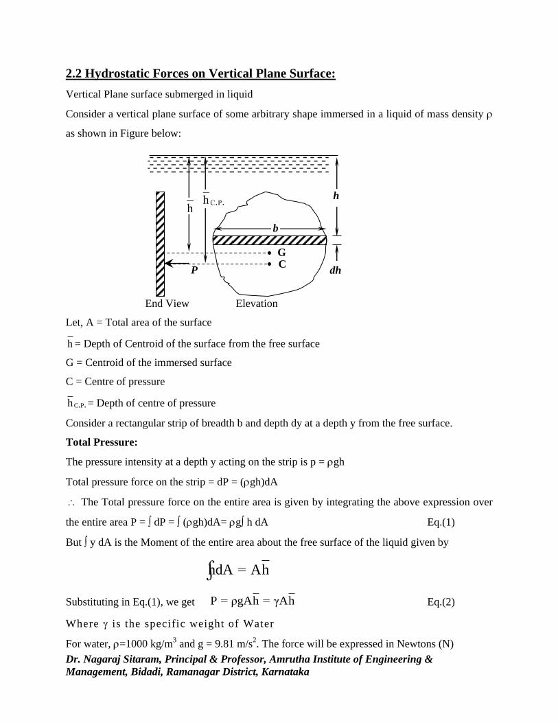
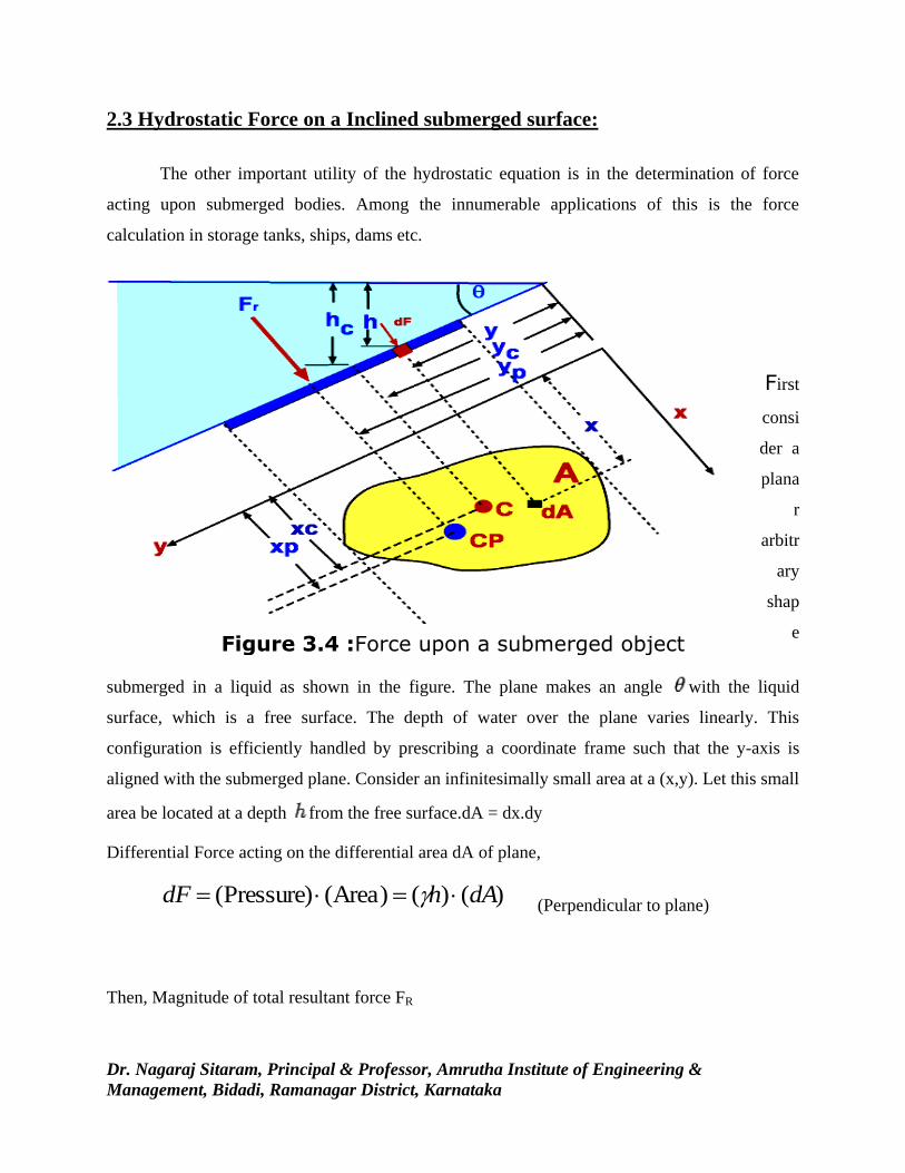
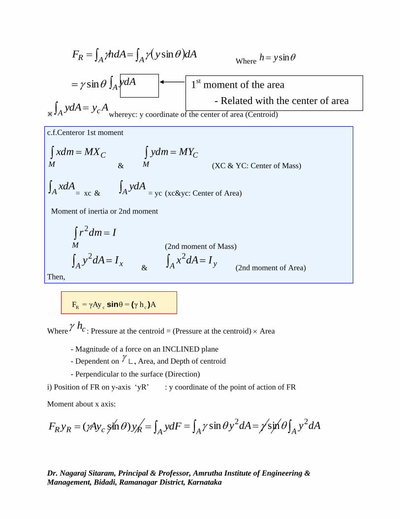
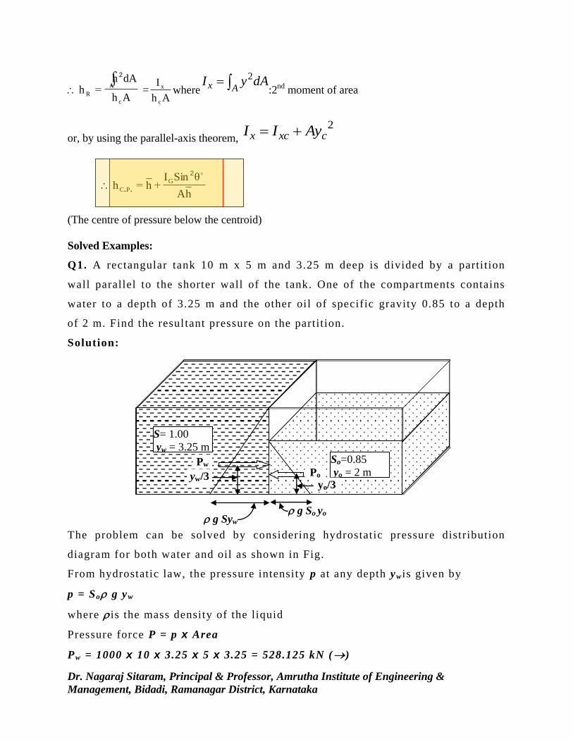


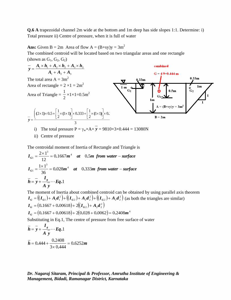
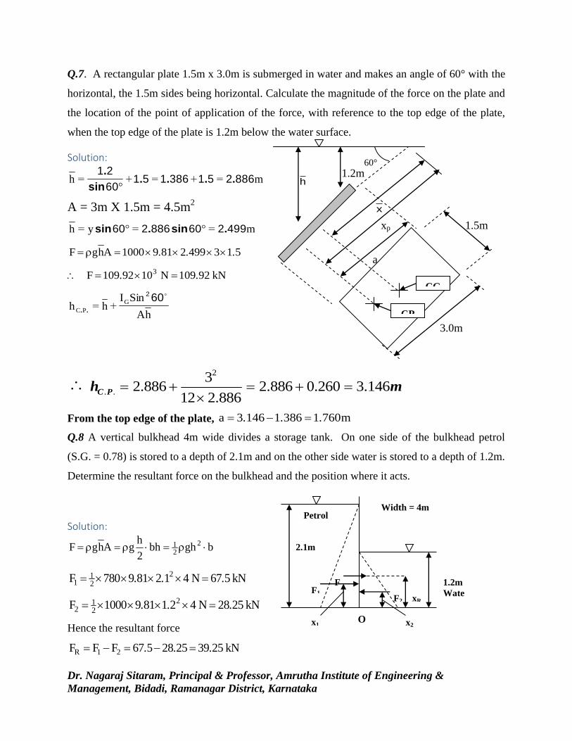
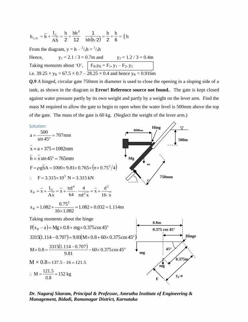


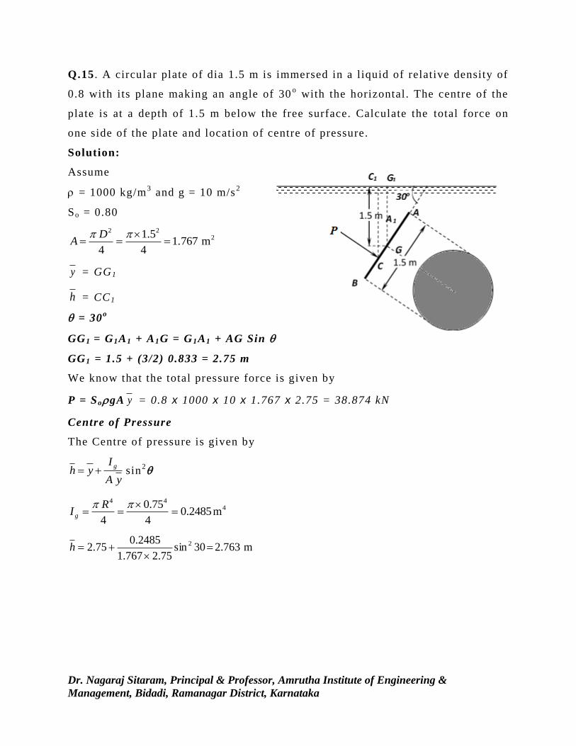


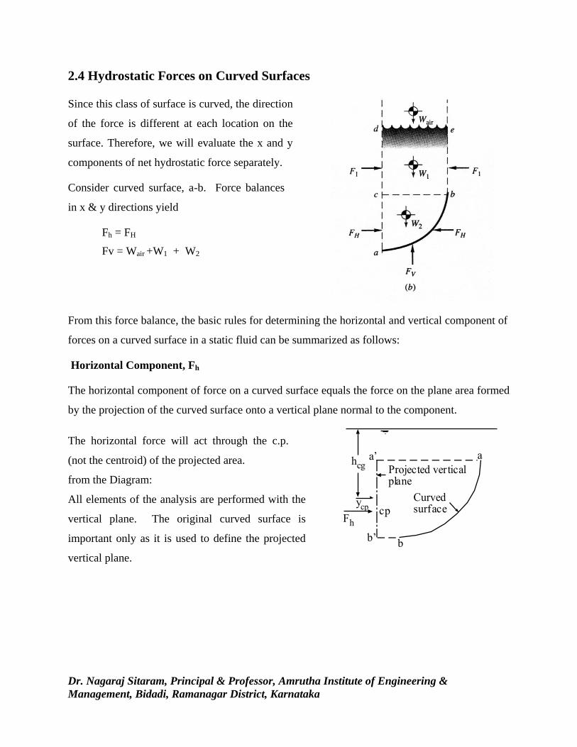


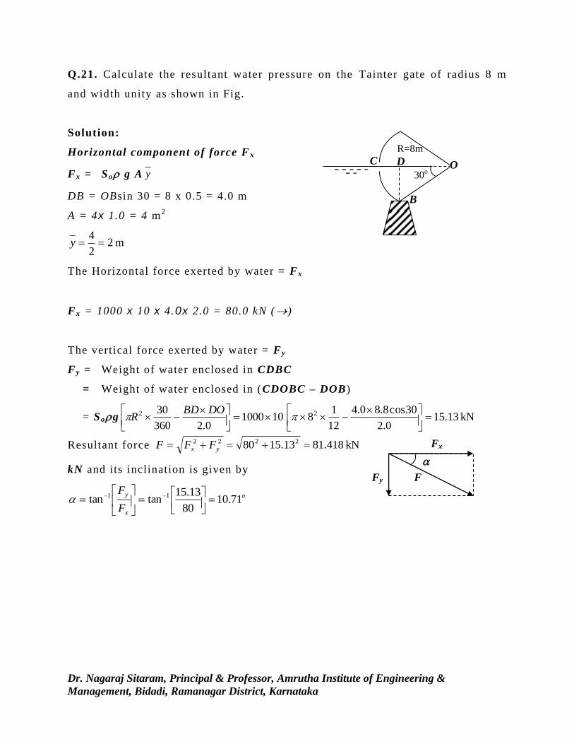
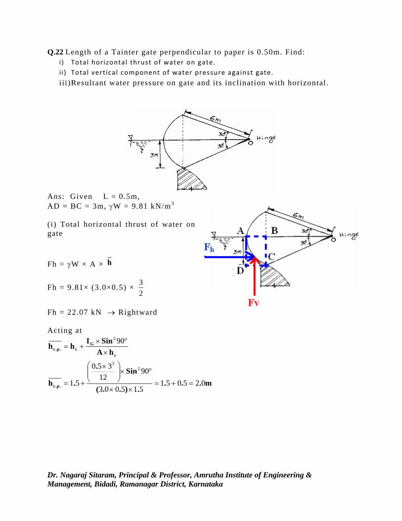


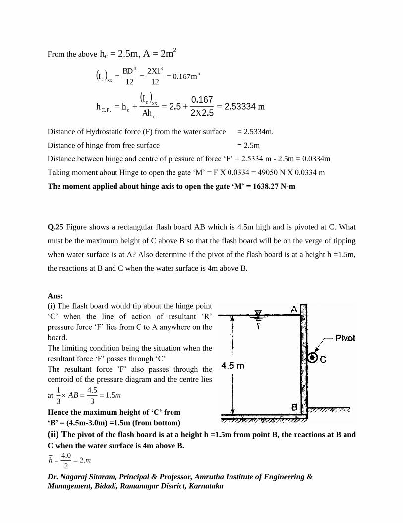

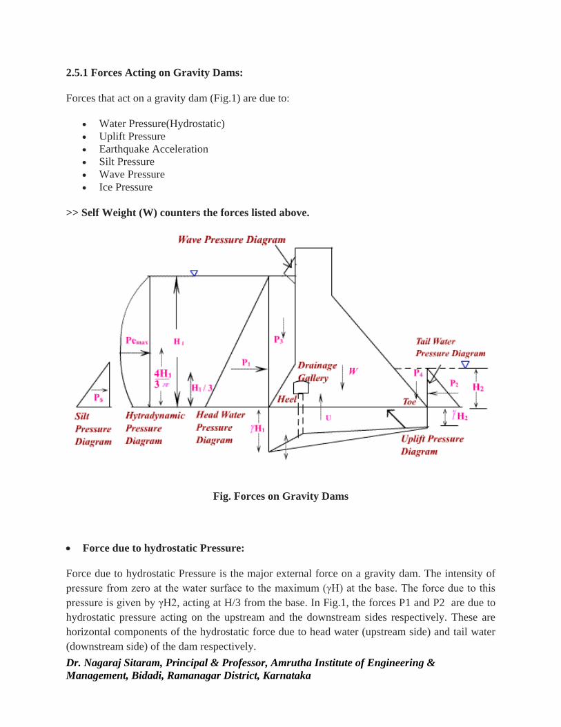


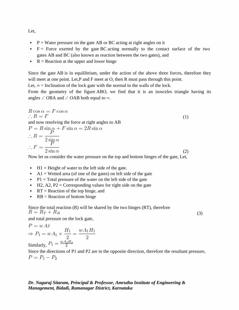

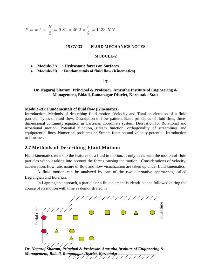


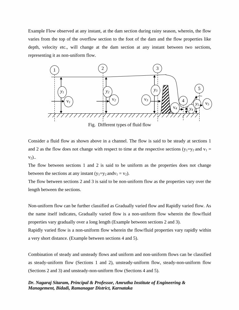


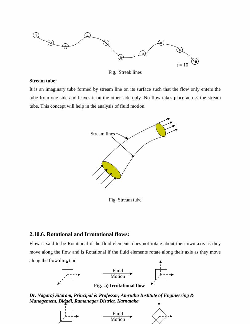


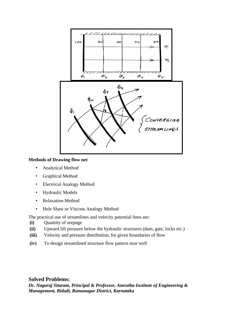
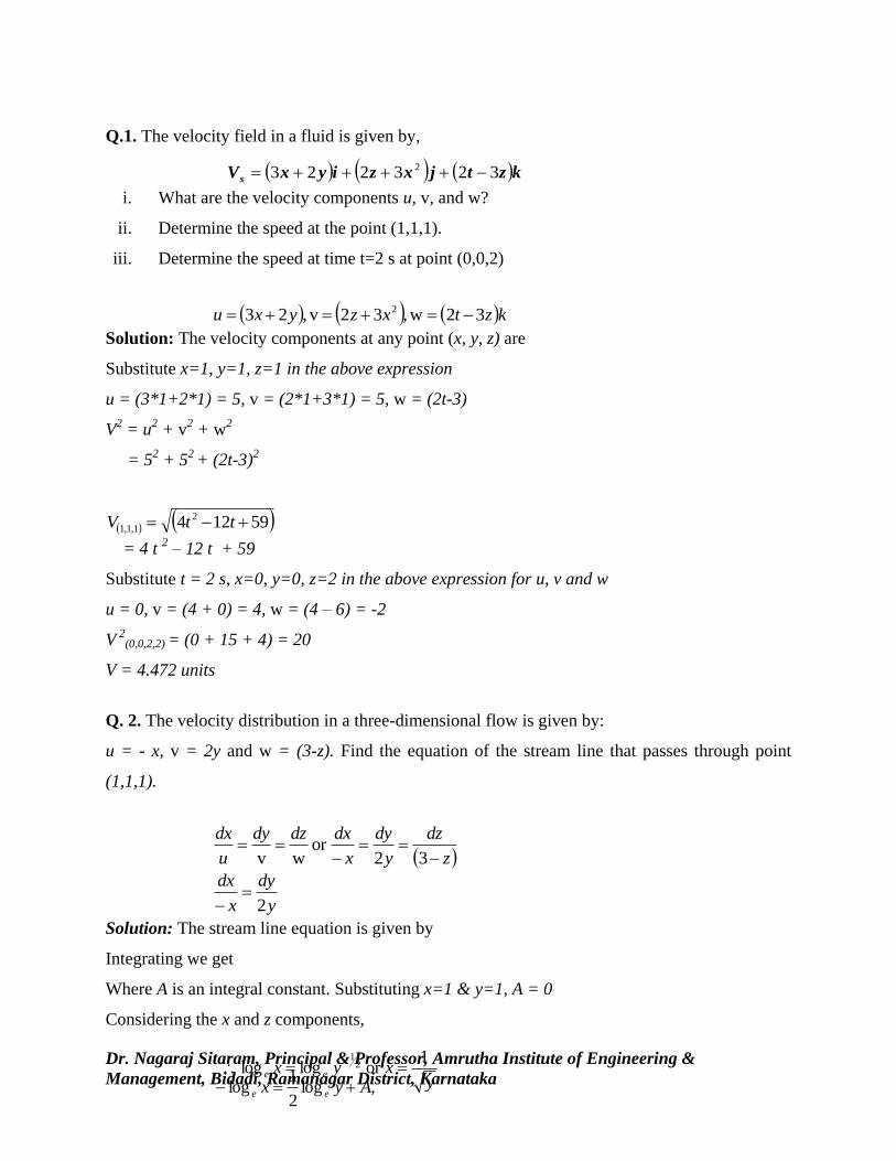

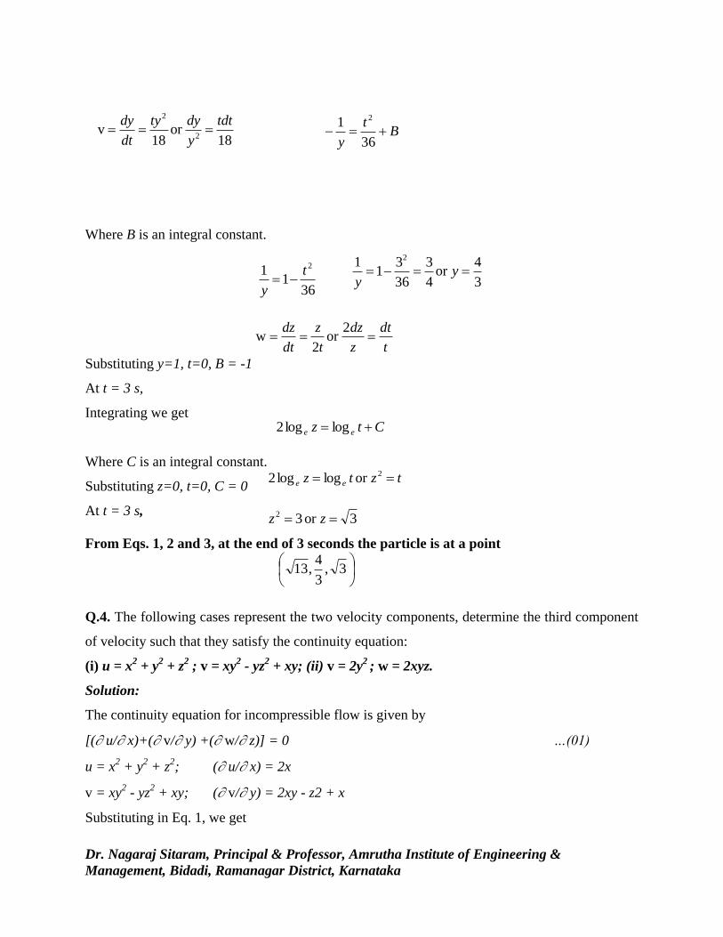

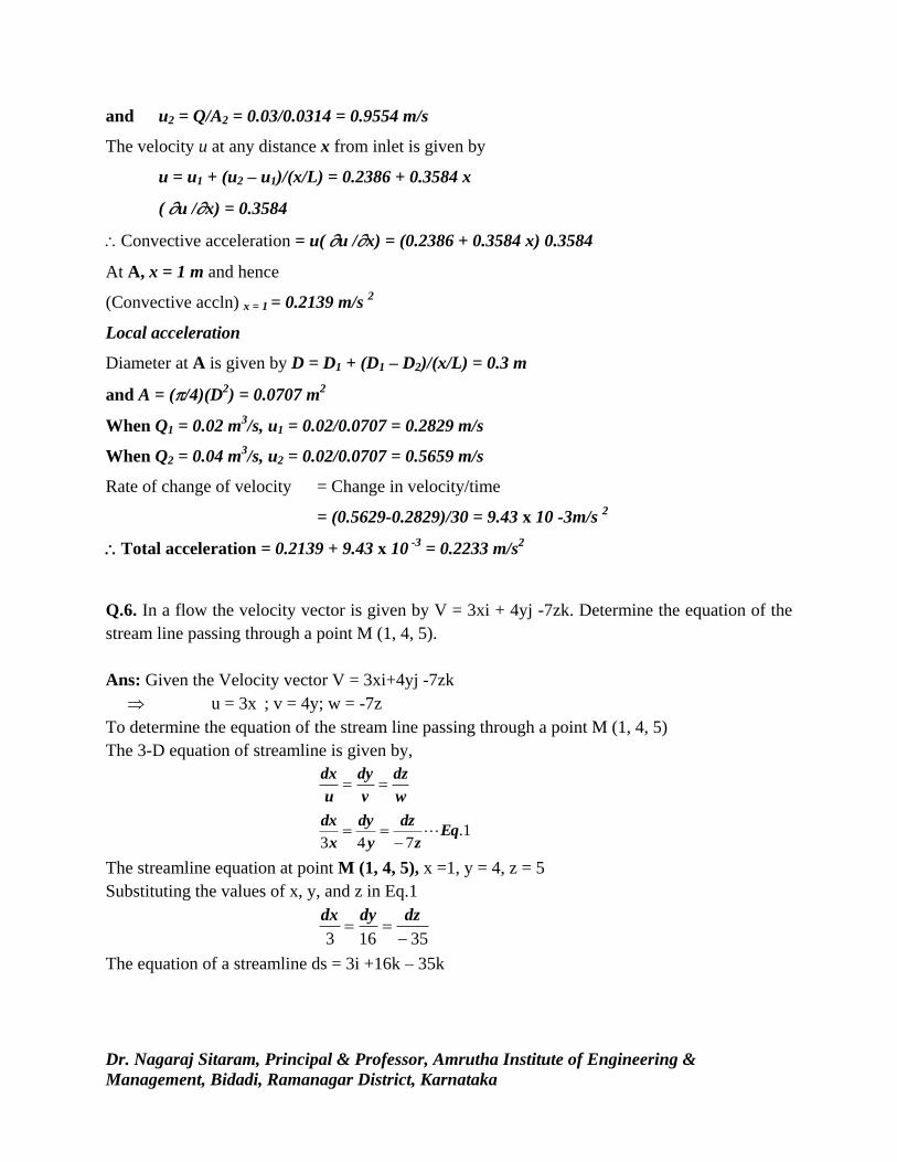

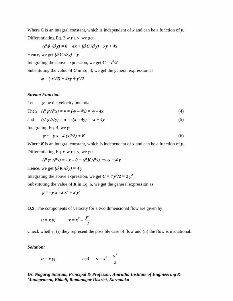
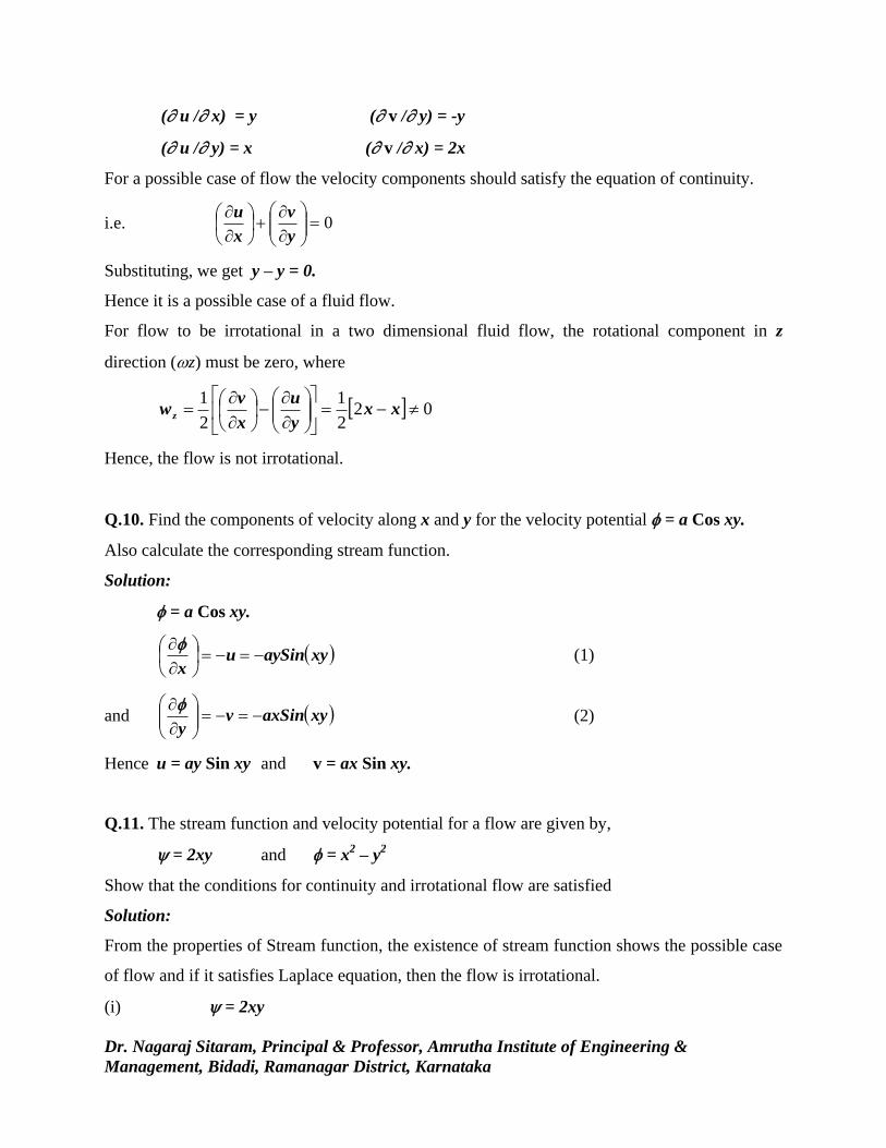
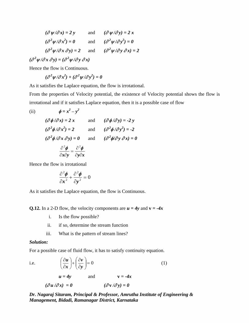
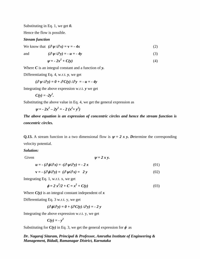

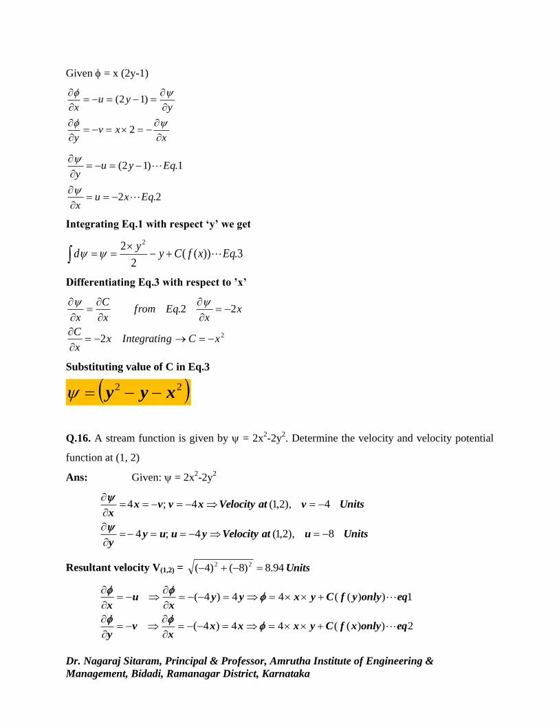

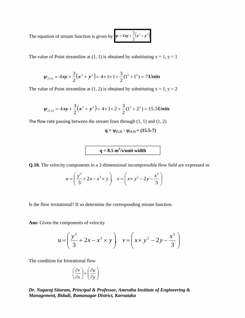
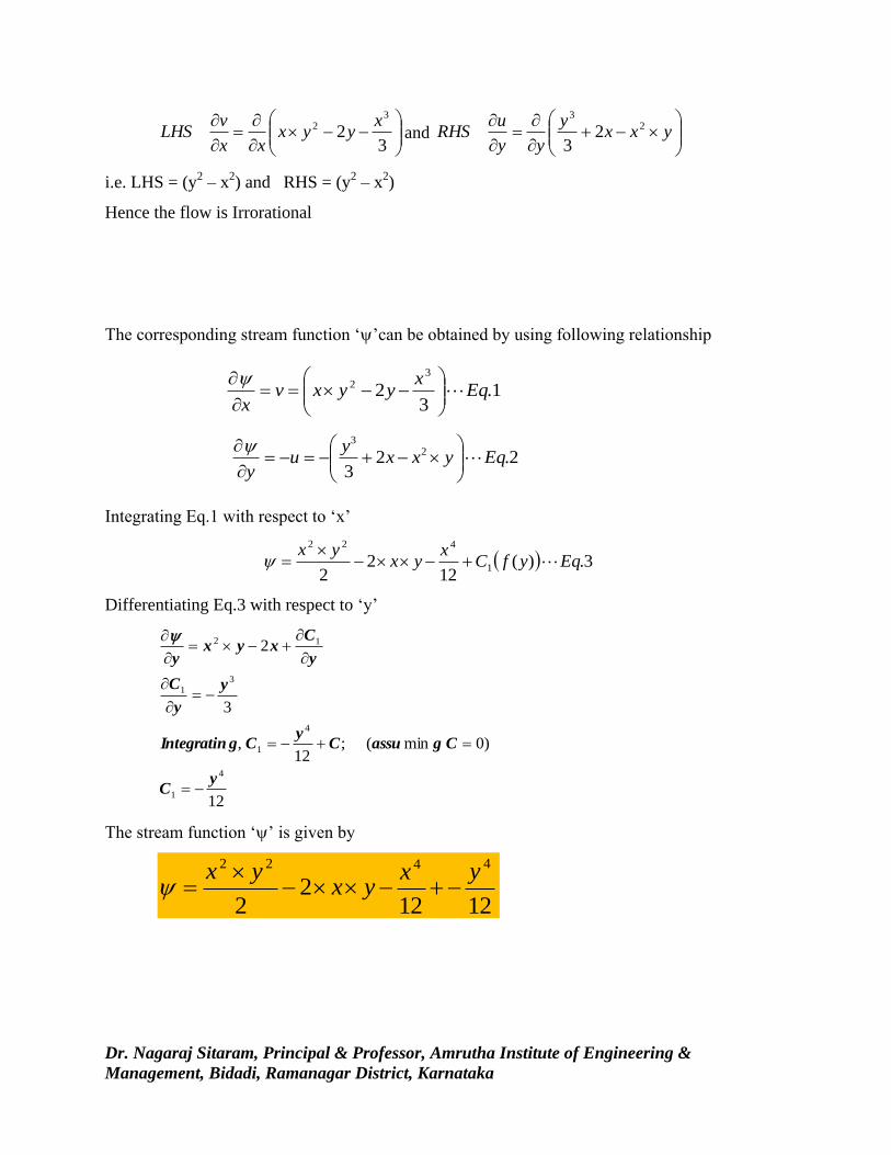


![Fluid Mechanics - Recently Added | An-Najah Videos · PDF file[3] Fall –2010 –Fluid Mechanics Dr. Mohammad N. Almasri [3-2] Fluid Statics Hydrostatic Forces on Submerged Plane](https://static.documents.pub/doc/80x56/5a8724087f8b9a14748d4e65/fluid-mechanics-recently-added-an-najah-videos-3-fall-2010-fluid-mechanics.jpg)


