C L I C C L I C 15 th October2008 CLIC 08 workshop Y. Papaphilippou, L. Rinolfi Injectors and Damping Rings working group summary Y. Papaphilippou (replacing S. Guiducci), L. Rinolfi CLIC 08 workshop
Transcript
C L I CC L I C
15th October2008CLIC 08 workshop Y. Papaphilippou, L. Rinolfi
Injectors and Damping Rings working group summary
Y. Papaphilippou (replacing S. Guiducci), L. Rinolfi
CLIC 08 workshop
C L I CC L I C
15th October2008CLIC 08 workshop Y. Papaphilippou, L. Rinolfi
Injectors and Damping Rings working group
A brief overview of the 2 days:
Number of talks: 26
A common session of 3 talks with “Instrumentation” and “Tests Facilities” working groups
Attendance: ≈ 25 to 30 persons in general for each session
26 speakers coming from 11 laboratories and universities: ANKA (D), ANL, BINP, CERN, Cockcroft Institute, FNAL, IPNL (Lyon), KEK, PSI, Lancaster University, LNF (Frascati),
C L I CC L I C
15th October2008CLIC 08 workshop Y. Papaphilippou, L. Rinolfi
The CLIC Main Beams Injector Complex has 3 studies corresponding to 3 configurations:
1) Base Line configuration:
The study is based on 3 TeV (c.m.) with unpolarized e+ source and with ultra low emittances for the Damping Rings.
2) Compton configuration:
The study is based on 3 TeV (c.m.) with polarized e+ source. The undulator option is considered as an alternative.
3) Low energy configuration:
The study is based on 500 GeV (c.m.) with relaxed beam parameters for the Damping Rings but with a double charge per bunch for the lepton sources.
Preliminary overview
C L I CC L I C
15th October2008CLIC 08 workshop Y. Papaphilippou, L. Rinolfi
The CLIC Injector complex in 2008
e- gun
LaserDC gunPolarized e-
Pre-injector Linac for e-
200 MeV
e-/Target
Pre-injector Linac for e+
200 MeV
Primary beam Linac for e-
5 GeV
Inje
ctor
Lin
ac
2.2
GeV
e+ DR
e+ PDR
Boo
ster
Lin
ac
6.6
GeV 4 GHz
e+ BC1 e- BC1
e+ BC2 e- BC2e+ Main Linac e- Main Linac
2 GHz
e- DR
e- PDR
2 GHz 2 GHz 2 GHz
4 GHz 4 GHz
12 GHz 12 GHz
9 GeV48 km
2.424 GeV 2.424 GeV
e
Target
AMD
2.424 GeV365 m 2.424 GeV
365 m
561 m
228 m
252 m 252 m
50 m 50 m
110 m 110 m
3 TeV
Base line configuration
C L I CC L I C
15th October2008CLIC 08 workshop Y. Papaphilippou, L. Rinolfi
NLC
(1 TeV)
CLIC 2008
(0.5 TeV)
CLIC 2008
(3 TeV)
ILC
(0.5 TeV)
E GeV 8 9 9 15
N 109 7.5 7 3.72 - 4 20
nb - 190 312 312 2625
tb ns 1.4 0.5 0.5 (6 RF periods) 369
tpulse ns 266 156 156 968925
x,y nm, nm 3300, 30 2400, 10 600, 10 8400, 24
z m 90-140 72 43 - 45 300
E 0.68 (3.2 % FW) 2 1.5 - 2 1.5
frep Hz 120 50 50 5
P kW 219 180 90 630
CLIC Main beam parameters
At the entrance of the Main Linac for e- and e+
C L I CC L I C
15th October2008CLIC 08 workshop Y. Papaphilippou, L. Rinolfi
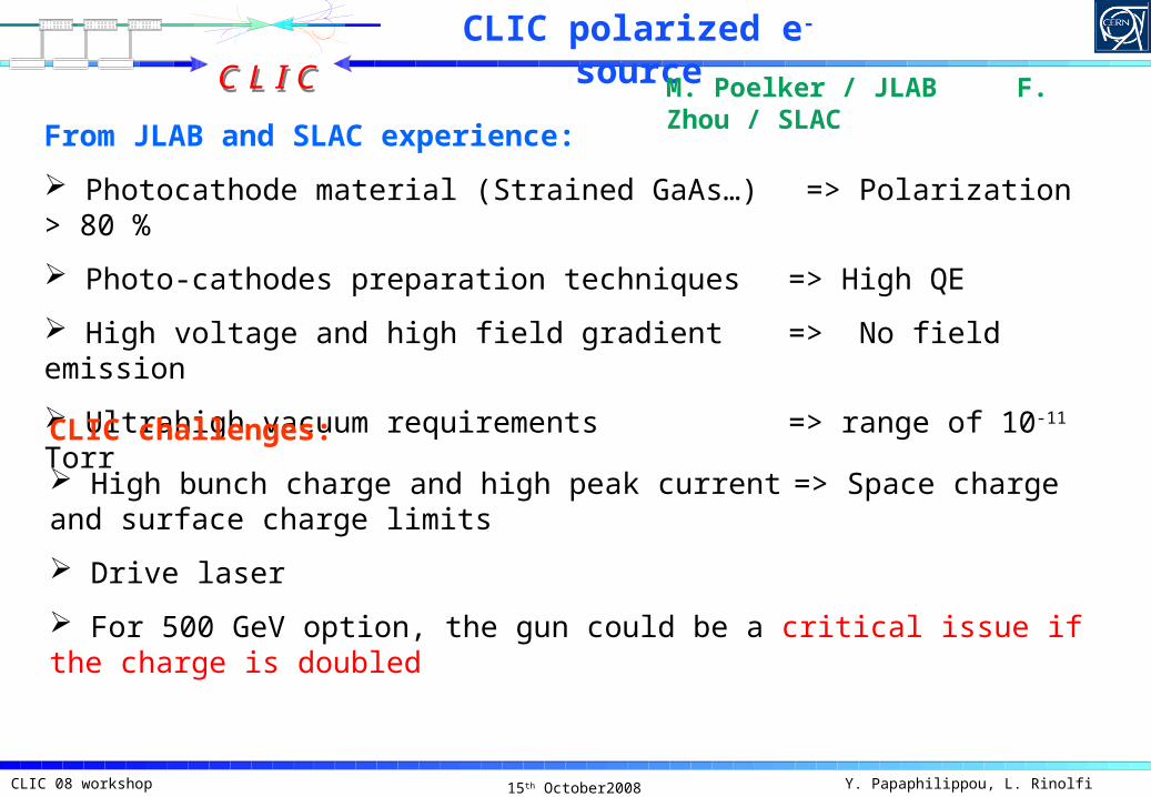
CLIC polarized e- source
From JLAB and SLAC experience:
Photocathode material (Strained GaAs…) => Polarization > 80 %
Photo-cathodes preparation techniques => High QE
High voltage and high field gradient => No field emission
Ultrahigh vacuum requirements => range of 10-11 Torr
CLIC challenges:
High bunch charge and high peak current => Space charge and surface charge limits
Drive laser
For 500 GeV option, the gun could be a critical issue if the charge is doubled
M. Poelker / JLAB F. Zhou / SLAC
C L I CC L I C
15th October2008CLIC 08 workshop Y. Papaphilippou, L. Rinolfi
Beam dynamics simulations in Linacs and TL
Transverse Longitudinal
Bunch length (rms) = 5 mm
Energy spread (rms) = 65 MeV
A. Latina / CERN
Injector Linac output
21 km Transfer Line with different FODO optics
Effects of long range wake fields remains to be studied for the Booster Linac
C L I CC L I C
15th October2008CLIC 08 workshop Y. Papaphilippou, L. Rinolfi
Unusual RF frequencies
a Beam axis
b
c
d
CLIC Injector
CLIC Booster
Units 2 GHz 2.856 GHz 4 GHz
a mm 22 15.4 11
b mm 64.3 45 32
c mm 50 35 25
d mm 42.8 30 21
G (unloaded) MV/m 17 25 36
G (loaded) 1.3 A MV/m 15 22 30
L m 4 4 3
NLC structure
No RF power sources available for these frequencies
C L I CC L I C
15th October2008CLIC 08 workshop Y. Papaphilippou, L. Rinolfi
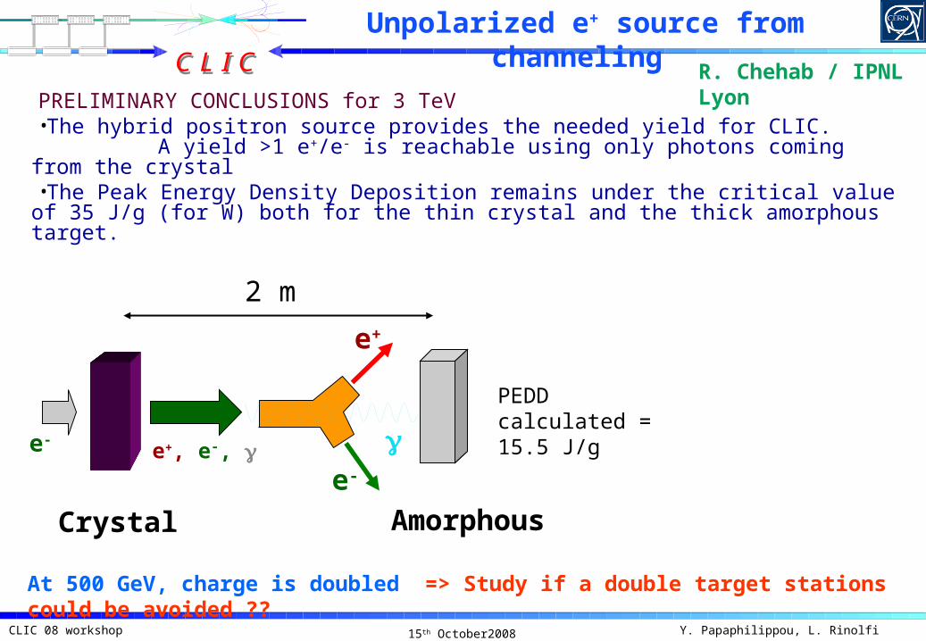
PRELIMINARY CONCLUSIONS for 3 TeV•The hybrid positron source provides the needed yield for CLIC.
A yield >1 e+/e- is reachable using only photons coming from the crystal•The Peak Energy Density Deposition remains under the critical value of
35 J/g (for W) both for the thin crystal and the thick amorphous target.
Unpolarized e+ source from channeling
R. Chehab / IPNL Lyon
e-
Crystal Amorphous
e+, e-, e-
e+
2 m
At 500 GeV, charge is doubled => Study if a double target stations could be avoided ??
PEDD calculated = 15.5 J/g
C L I CC L I C
15th October2008CLIC 08 workshop Y. Papaphilippou, L. Rinolfi
CLIC Compton Scheme
Collaboration on Positron Generation strongly supported by CLIC and ILC managements (J.P. Delahaye@PosiPol08)
J. Urukawa / KEK
ILC/CLIC common issues on Compton:
1) Number of e- (beam stability)
2) Optical cavity
3) High quality and high power laser
4) Choice of ERL parameters
5) Energy compression before (P)DR
6) Short Damping Time for (P)DR
7) e+ stacking
C L I CC L I C
15th October2008CLIC 08 workshop Y. Papaphilippou, L. Rinolfi
2 flat mirrors
2 spherical mirrors
e-
Injection laser
A. Variola / LAL
Optical cavity R&D at LAL
GOAL => store the maximum power with a very short pulse for ComptonAt low power, LAL results: i) finesse = 30000; ii) waists of the order of few tenths of microns;iii) studied the best 4 mirrors cavity configurations due to the polarization effects on modes.
The results will be rescaled and dimensioned for the proposal of the polarized positron source for the CLIC based on Compton scattering
Install the system @ ATF KEK
C L I CC L I C
15th October2008CLIC 08 workshop Y. Papaphilippou, L. Rinolfi
A possible CLIC layout with undulator based e+ source
Following the tunnel back to e+ injector
e- e+
Booster lin
ac
e+ main linac
e- main linac
e+ capturing optics and preaccelerator
undulator
Bending assemblies, 20 of them, each one bends the electron beam by 1/20 of the angle between axis of undulator and the axis of the rest of electron main linac
target
>2m
e+ capturing etc
undulator
W. Gai / ANL
Simulations shows that the undulator will not dilute the emittance of the e- beam.
C L I CC L I C
15th October2008CLIC 08 workshop Y. Papaphilippou, L. Rinolfi
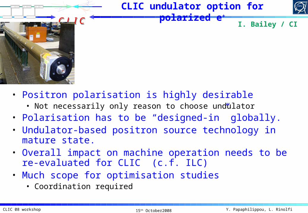
• Positron polarisation is highly desirable• Not necessarily only reason to choose undulator
• Polarisation has to be “designed-in” globally.• Undulator-based positron source technology in mature
state.• Overall impact on machine operation needs to be re-
evaluated for CLIC (c.f. ILC)• Much scope for optimisation studies
• Coordination required
I. Bailey / CI
CLIC undulator option for polarized e+
C L I CC L I C
15th October2008CLIC 08 workshop Y. Papaphilippou, L. Rinolfi
The RTML is not a passive beam transport but an active beam tuning element
Misalignments, Magnetic field errors, wake fields, RF voltage and phase, synchrotron radiations, beam-gas interaction,…
F. Stulle / CERN
Challenges to transport beam from DR to ML
C L I CC L I C
15th October2008CLIC 08 workshop Y. Papaphilippou, L. Rinolfi
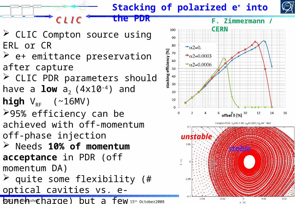
Stacking of polarized e+ into the PDR
CLIC Compton source using ERL or CR e+ emittance preservation after capture CLIC PDR parameters should have a low a2 (4x10⁻⁴) and high VRF (~16MV)95% efficiency can be achieved with off-momentum off-phase injection Needs 10% of momentum acceptance in PDR (off momentum DA) quite some flexibility (# optical cavities vs. e- bunch charge) but a few challenges for PDR design
unstable
stable
F. Zimmermann / CERN
C L I CC L I C
15th October2008CLIC 08 workshop Y. Papaphilippou, L. Rinolfi
For general TME cells the focal lengths (under thin lens approximation) can be written as a function of the drifts and the transverse emittance
Enables optimization of any type of optics parameter
Guide to design optimal CLIC (P)DRs Example: optics design of PDR
F. Antoniou / CERN
Analytical solution for TME cells
C L I CC L I C
15th October2008CLIC 08 workshop Y. Papaphilippou, L. Rinolfi
New arc cell design Increasing space between magnets,
reducing magnet strengths to realistic levels
Reducing chromaticity, increasing DA Even if equilibrium emittance is
Alternative cell based on SUPERB lattice Using 2 dipoles per cell with a
focusing quadrupole in the middle
Good optics properties To be evaluated for performance
when IBS is included
K. Zolotarev / BINP P. Raimondi / LNF
New arc cells optics for the Damping rings
C L I CC L I C
15th October2008CLIC 08 workshop Y. Papaphilippou, L. Rinolfi
Two models (2.8T, 40mm period) Vertical racetrack (WR) Double helix (WH), can
reach 3.2T with Holmium pole tips
Apart from higher field Nb3Sn can sustain higher heat load (10W/m) than NbTi (1W/m)
Between 2009-2010, two short prototypes will be built, tested at CERN and magnetically measured at ANKA
R. Maccaferri / CERN P. Peiffer / ANKA
Nb3Sn Wiggler Design
C L I CC L I C
15th October2008CLIC 08 workshop Y. Papaphilippou, L. Rinolfi
Present design uses NbTi wet wire in separate poles clamped together (2.5T, 5cm period)
Performance tests by the end of the year on short prototype
Magnetic tolerances needed to refine design (e.g. taken from PETRA III wiggler)
Alternative design allows using Nb3Sn dry wire substantially reducing time and cost
P. Vobbly / BINP
NbTi Wiggler Design
C L I CC L I C
15th October2008CLIC 08 workshop Y. Papaphilippou, L. Rinolfi
4 5 6 7 8 9 100
5
10
15
20
25
30
35
40
Vertial colimaor gap size, mm
Load f
or
W4 c
ham
ber,
W
gap 10 mm
gap 11 mmgap 12 mm
gap 13 mm
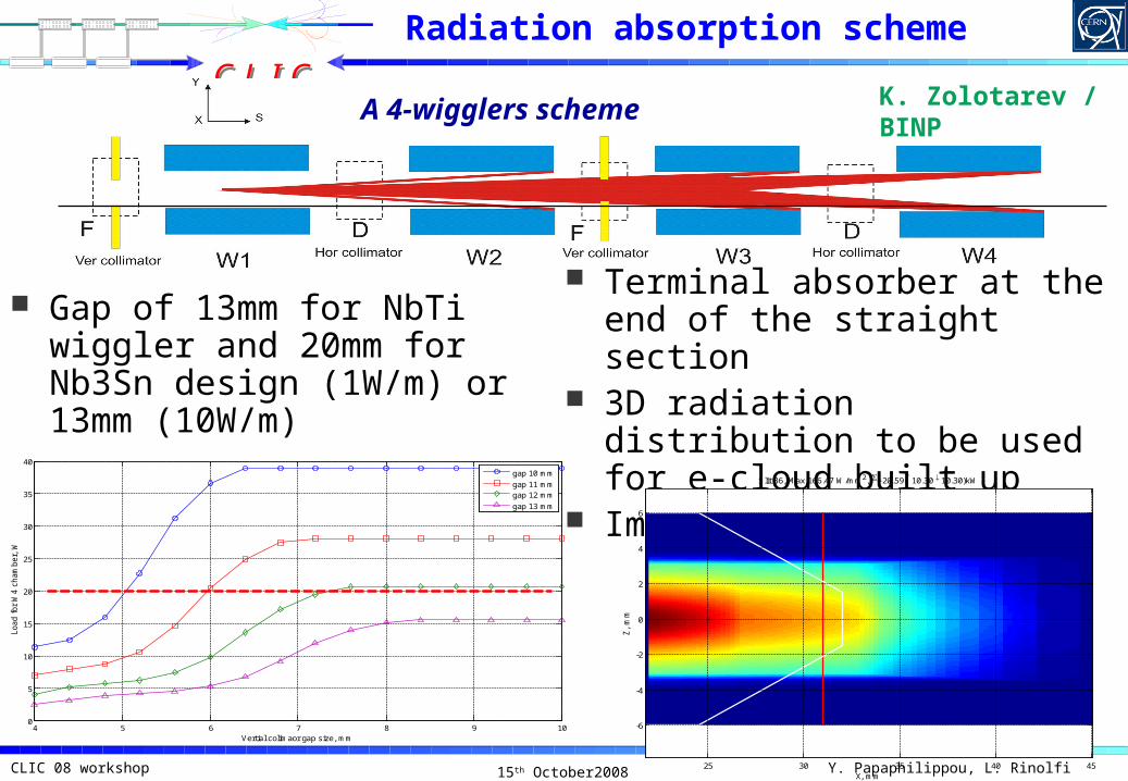
A 4-wigglers scheme
Gap of 13mm for NbTi wiggler and 20mm for Nb3Sn design (1W/m) or 13mm (10W/m)
Terminal absorber at the end of the straight section
3D radiation distribution to be used for e-cloud built up
Impedance estimation
X, mm
Z,
mm
Slit 36, Max 166.47 W/mm2, =20.59( 10.30 10.30)kW
25 30 35 40 45
-6
-4
-2
0
2
4
6
K. Zolotarev / BINP
Radiation absorption scheme
C L I CC L I C
15th October2008CLIC 08 workshop Y. Papaphilippou, L. Rinolfi
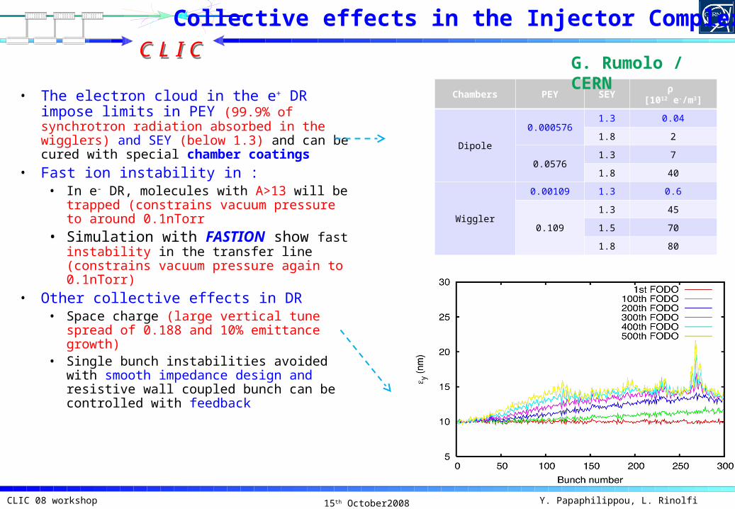
• The electron cloud in the e+ DR impose limits in PEY (99.9% of synchrotron radiation absorbed in the wigglers) and SEY (below 1.3) and can be cured with special chamber coatings
• Fast ion instability in :• In e- DR, molecules with A>13 will be
trapped (constrains vacuum pressure to around 0.1nTorr
• Simulation with FASTION show fast instability in the transfer line (constrains vacuum pressure again to 0.1nTorr)
• Other collective effects in DR• Space charge (large vertical tune spread
of 0.188 and 10% emittance growth)• Single bunch instabilities avoided with
smooth impedance design and resistive wall coupled bunch can be controlled with feedback
Chambers PEY SEYρ
[1012 e-/m3]
Dipole
0.0005761.3 0.04
1.8 2
0.05761.3 7
1.8 40
Wiggler
0.00109 1.3 0.6
0.109
1.3 45
1.5 70
1.8 80
G. Rumolo / CERN
Collective effects in the Injector Complex
C L I CC L I C
15th October2008CLIC 08 workshop Y. Papaphilippou, L. Rinolfi
Bakeable system-NEG gives SEY<1.3 for baking @ > 180C-the evolution after many venting cycles should be studied-NEG provides pumping-it is also conceivable to develop a coating with lower activation T
Non-bakeable system- a-C coating provides SEY< 1 (2h air exposure), SEY<1.3 (1week air exposure)-after 2 months exposure in the SPS vacuum or 15 days air exposure no increase of e-cloud activity-pumpdown curves can be as good as for stainless steel (measurements in progress in lab and ESRF)-no particles and peel-off-to be characterized for impedance and PEY
1.3
Henrist et al. Appl.Surf.Sci,2001
M. Taborelli / CERN
Surface Treatment for e- Cloud Mitigation
C L I CC L I C
15th October2008CLIC 08 workshop Y. Papaphilippou, L. Rinolfi
The Keil-Schnell-Boussard criterion gives an instability threshold of around 170 mW for ILC DR
Calculated effective impedance from 690 BPMs of around 70 mW;
Perturbative approach for analytical computation of wake-fields from moving charge in a circular pipe with planar curvature
M. Korostelev / CI
R. Tucker / Lancaster
BPMs impedance in ILC DR
C L I CC L I C
15th October2008CLIC 08 workshop Y. Papaphilippou, L. Rinolfi
IBS effect evaluated through semi analytical approach (modified Piwinski or Bjorken-Mtingwa formalism)
Derive analytically the optics parameters for reaching minimum IBS dominated emittance in selected lattices (FODO, TME,…)
Numerical or analytical approach for effect of strong IBS producing non-Gaussian tails including radiation damping is missing
Codes for non-Gaussian beams exist (e.g. MOCAC) but not all effects included
Use of stochastic diffusion equation approach may be an alternative (presently used for coasting beams)
0 100 200 300 400 500Time, sec
5.0E-6
7.0E-6
9.0E-6
1.1E-5
x ,
y, m
rad
X plane, AM modelY plane, AM modelX plane, BCM modelY plane, BCM model
Nw wires
M. Martini / CERN
Intrabeam scattering
C L I CC L I C
15th October2008CLIC 08 workshop Y. Papaphilippou, L. Rinolfi
1) Main issues:•Frequency: 2 GHz•Highest peak and average power•Very strong beam loading transient effects (beam power
of ~5 MW during 156 ns, no beam power during the other 1060 ns)
•Small stored energy at 2 GHz•High energy loss per turn at relatively low voltage
results in big sin φs = 0.95 (any examples of operation ?)•Wake-fields•Pulsed heating related problem (fatigue, …)
2) Recommendations:•Reduce energy loss per turn and/or increase RF voltage•Consider 1GHz frequency (RF system becomes
conventional, RF power reduced, but delay loop for recombination is necessary and emittance budget is tight)
A. Grudiev / CERN
CLIC DR RF system
C L I CC L I C
15th October2008CLIC 08 workshop Y. Papaphilippou, L. Rinolfi
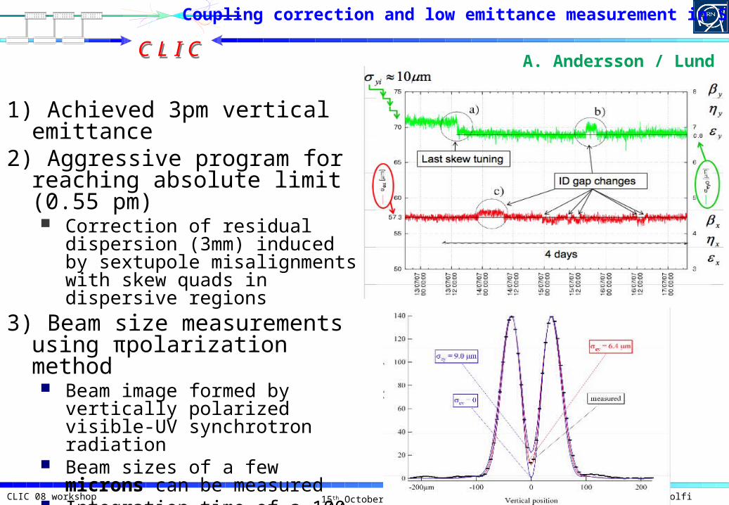
1) Achieved 3pm vertical emittance
2) Aggressive program for reaching absolute limit (0.55 pm) Correction of residual
dispersion (3mm) induced by sextupole misalignments with skew quads in dispersive regions
3) Beam size measurements using πpolarization method Beam image formed by
15th October2008CLIC 08 workshop Y. Papaphilippou, L. Rinolfi
Conclusion
2) Two new ILC/CLIC working groups are in place for:
i) Damping Rings
ii) e+ sources
a) For the Base Line configuration, crucial studies remain to be performed.
3) The CLIC Main Beam Injector Complex is considered as a classical ensemble based on conventional technology which should provide the requested beam parameters at the entrance of the Main Linacs (easily):
BUT
b) For polarized e+, an intense R&D is necessary.
c) For the 500 GeV option, requesting a double charge per bunch, intense studies are necessary to confirm the feasibility (at lower cost).
1) Enormous progress have been made for the CLIC Main Beam Injector Complex since the last CLIC workshop