U.S. Department of Transportation Federal Aviation Administration Advisory Circular Subject: MEASUREMENT, CONSTRUCTION, AND MAINTENANCE OF SKID-RESISTANT AIRPORT PAVEMENT SURFACES Date: 3/18/97 Initiated by: AAS-100 AC No: 150/5320-12C Change: 1. PURPOSE. This advisory circular (AC) contains guidelines and procedures for the design and construction of skid-resistant pavement, pavement evaluation with friction measuring equipment, and maintenance of high skid-resistant pavements. 2. CANCELLATION. AC 150/5320-12B, Measurement, Construction, and Maintenance of Skid- Resistant Airport Pavement Surfaces, dated November 12, 1991, is canceled. 3. RELATED READING MATERIAL. Appendix 2 contains a listing of documents containing supplemental material relating to the subject. Information on ordering these documents is also provided. 4. APPLICATION. The guidelines and standards contained herein are recommended by the Federal Aviation Administration (FAA) for applications involving runway friction measurement, construction, and maintenance. For airport projects funded under Federal grant assistance programs, the standards identified by BOLDFACE CAPITALS in chapter 2, section 4, paragraphs 2-21 and 2-22 and those in appendix 3 are mandatory. 5. BACKGROUND. With the introduction of turbojet aircraft, braking performance on pavement surfaces has become more critical. Under certain conditions, hydroplaning or unacceptable loss of traction can occur, resulting in poor braking performance and possible loss of directional control. To address this concern, a number of research projects were conducted by the National Aeronautics and Space Administration (NASA), FAA, United States Air Force (USAF), and various foreign governments. These efforts concentrated in two major areas: (a) high skid- resistant pavement surface design and evaluation and (b) application of proper maintenance techniques and procedures. In this circular, guidelines are provided to airport operators on how to locate and restore areas on the pavement surface where friction has deteriorated below acceptable levels for aircraft braking performance. The material contained in this circular summarizes the findings of these research efforts. 6. METRIC UNITS. To promote an orderly transition to metric (SI) units, this circular contains both English and metric dimensions. The metric conversions may not be exact equivalents and, until there is an official changeover to the metric system, the English dimensions will govern. DAVID L. BENNETT Director, Office of Airport Safety and Standards
Transcript
U.S. Departmentof Transportation
Federal AviationAdministration
AdvisoryCircular
Subject: MEASUREMENT, CONSTRUCTION, ANDMAINTENANCE OF SKID-RESISTANT AIRPORTPAVEMENT SURFACES
Date: 3/18/97Initiated by: AAS-100
AC No: 150/5320-12CChange:
1. PURPOSE. This advisory circular (AC)contains guidelines and procedures for the design andconstruction of skid-resistant pavement, pavementevaluation with friction measuring equipment, andmaintenance of high skid-resistant pavements.
2. CANCELLATION. AC 150/5320-12B,Measurement, Construction, and Maintenance of Skid-Resistant Airport Pavement Surfaces, dated November12, 1991, is canceled.
3. RELATED READING MATERIAL.Appendix 2 contains a listing of documents containingsupplemental material relating to the subject.Information on ordering these documents is alsoprovided.
4. APPLICATION. The guidelines and standardscontained herein are recommended by the FederalAviation Administration (FAA) for applicationsinvolving runway friction measurement, construction,and maintenance. For airport projects funded underFederal grant assistance programs, the standardsidentified by BOLDFACE CAPITALS in chapter 2,section 4, paragraphs 2-21 and 2-22 and those inappendix 3 are mandatory.
5. BACKGROUND. With the introduction ofturbojet aircraft, braking performance on pavementsurfaces has become more critical. Under certainconditions, hydroplaning or unacceptable loss oftraction can occur, resulting in poor brakingperformance and possible loss of directional control.To address this concern, a number of research projectswere conducted by the National Aeronautics and SpaceAdministration (NASA), FAA, United States Air Force(USAF), and various foreign governments. Theseefforts concentrated in two major areas: (a) high skid-resistant pavement surface design and evaluation and(b) application of proper maintenance techniques andprocedures. In this circular, guidelines are provided toairport operators on how to locate and restore areas onthe pavement surface where friction has deterioratedbelow acceptable levels for aircraft brakingperformance. The material contained in this circularsummarizes the findings of these research efforts.
6. METRIC UNITS. To promote an orderlytransition to metric (SI) units, this circular containsboth English and metric dimensions. The metricconversions may not be exact equivalents and, untilthere is an official changeover to the metric system, theEnglish dimensions will govern.
DAVID L. BENNETTDirector, Office of Airport Safety and Standards
3/18/97 AC 150/5320-12C
iii
CONTENTS
Paragraph Page
CHAPTER 1. OVERVIEW
1-1. Purpose................................................................................................................................................................. 11-2. Background .......................................................................................................................................................... 11-3. Pavement Design Research ................................................................................................................................... 11-4. Pavement Maintenance and Evaluation Research.................................................................................................. 11-5. Friction Measuring Equipment Research .............................................................................................................. 21-6. Additional Background and Information............................................................................................................... 2
CHAPTER 2. DESIGN AND CONSTRUCTION OF SKID-RESISTANT PAVEMENT
Section 1. Basic Design Considerations
2-1. General................................................................................................................................................................. 32-2. Surface Texture and Drainage .............................................................................................................................. 32-3. Painted Areas On Pavement Surfaces.................................................................................................................... 3
2-9. Construction Techniques for PCC Pavement......................................................................................................... 52-10. Timing and Curing............................................................................................................................................... 52-11. Brush or Broom Finish ......................................................................................................................................... 52-12. Burlap Drag Finish............................................................................................................................................... 52-13. Wire Combing...................................................................................................................................................... 52-14. Wire Tined ........................................................................................................................................................... 6
Section 4. Runway Grooving
2-15. General Grooving Techniques .............................................................................................................................. 62-16. Determining Need for Grooving ........................................................................................................................... 62-17. Suitability of Existing Pavements for Grooving..................................................................................................... 62-18. Overlays ............................................................................................................................................................... 72-19. HMA Pavement Grooving .................................................................................................................................... 72-20. PCC Pavement Grooving ...................................................................................................................................... 72-21. FAA Specifications for Runway Grooving ............................................................................................................ 72-22. Grooving Runway Intersections and Angled Exit Taxiways .................................................................................. 8
AC 150/5320-12C 3/18/97
Page
iv
CHAPTER 3. PAVEMENT EVALUATION
Section 1. Need for and Frequency of Evaluation
3-1. Friction Deterioration..........................................................................................................................................193-2. Scheduling Pavement Evaluations.......................................................................................................................193-3. Minimum Friction Survey Frequency ..................................................................................................................193-4. Surveys Without Continuous Friction Measuring Equipment (CFME).................................................................193-5. Groove Deterioration...........................................................................................................................................203-6. Measurement of Pavement Surface Texture.........................................................................................................20
Section 2. CFME - General
3-7. General Requirements for CFME ........................................................................................................................203-8. FAA Performance Standards for CFME ..............................................................................................................203-9. FAA Qualified Product List.................................................................................................................................203-10. Use of Decelerometer ..........................................................................................................................................203-11. Federal Funding of CFME ..................................................................................................................................203-12. Training of Personnel..........................................................................................................................................203-13. Calibration..........................................................................................................................................................20
Section 3. Conducting Friction Evaluation with CFME
3-14. Preliminary Steps................................................................................................................................................213-15. Location of Friction Surveys on the Runway........................................................................................................213-16. Vehicle Speed for Conducting Surveys................................................................................................................213-17. Use of CFME Self-Wetting System .....................................................................................................................213-18. Friction Surveys During Rainfall.........................................................................................................................213-19. Friction Level Classification................................................................................................................................223-20. Evaluation and Maintenance Guidelines .............................................................................................................223-21. Computer Evaluation of Friction Test Data .........................................................................................................23
Section 4. Conducting Texture Depth Measurements
3-22. Recommended Testing ........................................................................................................................................233-23 Recommended Texture Depth .............................................................................................................................233-24. Location Of Measurements..................................................................................................................................233-25. Test Methods ......................................................................................................................................................233-26. Computation .......................................................................................................................................................24
CHAPTER 4. MAINTAINING HIGH SKID-RESISTANCE
Section 1. Maintenance Considerations
4-1. Need for Maintenance .........................................................................................................................................28
Appendix 1. Qualification Process for CFME (1 page)Appendix 2. Related Reading Material (2 pages)Appendix 3. Performance Specifications for CFME (2 pages)Appendix 4. FAA-Approved CFME (1 page)Appendix 5. Training Requirements Outline for CFME (1 page)
FIGURES
Figure 2-1 Edge View of PFC Overlay ....................................................................................................................... 9Figure 2-2 Aggregate Slurry Seal............................................................................................................................. 10Figure 2-3 Heavy Paving Broom Finish ................................................................................................................... 11Figure 2-4 Heavy Burlap Drag Finish ...................................................................................................................... 11Figure 2-5 Wire Comb Technique Constructed at Patrick Henry Airport, Virginia,
Using a 1/8 " x 1/8 " x 1/2" Configuration .............................................................................................. 12Figure 2-6 Sawed Grooves in HMA Pavement ......................................................................................................... 13Figure 2-7 Sawed Grooves in PCC Pavement........................................................................................................... 13Figure 2-8 Plastic Grooving Technique Using a Vibrating Ribbed Plate................................................................... 14Figure 2-9 Plastic Grooving Technique Using a Ribbed Roller Tube ........................................................................ 15Figure 2-10 Grooving Intersections of Primary and Secondary Runways.................................................................... 16Figure 2-11 Grooving High Speed or Angled Exit Taxiways...................................................................................... 17Figure 3-1 Grease-Volume Measuring Tube, Plunger, and Rubber Squeegee............................................................ 25Figure 3-2 Measuring Tube Dimensions to Measure One Cubic Inch or Fifteen Cubic Centimeters.......................... 26Figure 3-3 Measuring Tube Filled with Grease ........................................................................................................ 27Figure 3-4 Illustration of Apparatus Used in Grease Application Technique For
1-1. PURPOSE. This AC provides guidelines fordesigning, constructing, and maintaining skid-resistantairport pavement surfaces and for conductingevaluations and surveys of runway friction forpavement maintenance purposes. It also containsperformance specifications for friction measuringequipment. Guidance on pavement frictionmeasurement for aircraft operational purposes duringwinter weather and performance standards fordecelerometers are found in AC 150/5200-30, AirportWinter Safety and Operations.
1-2. BACKGROUND. Since the advent of turbojetaircraft with their greater weight and high landingspeeds, braking performance on runway surfaces,particularly when wet, has become a significant safetyconsideration. A number of research programs byFAA, NASA, and USAF, as well as those performed byforeign governments, have been directed in two majorareas: original pavement surface design to maximizeskid-resistance with proper materials and constructiontechniques and effective evaluation and maintenancetechniques to detect deterioration of skid-resistance andto restore it to acceptable levels.
1-3. PAVEMENT DESIGN RESEARCH.Pavement grooving was the first major step inachieving safer pavement surfaces for aircraftoperations in wet weather conditions. These studieswere completed by NASA at the Langley ResearchCenter, Langley, Virginia, in 1968. The FAA, throughits Technical Center in Atlantic City, New Jersey,directed a test program on pavement surface treatmentsat the Naval Air Engineering Center, Lakehurst, NewJersey. The study was completed in 1983. Both theNASA Langley and the FAA Technical Center studiesshowed that a high level of friction could be achievedon wet pavement by forming or cutting closely spacedtransverse grooves on the runway surface, which wouldallow rain water to escape from beneath tires oflanding aircraft. Other research conducted both in theUnited Kingdom and the United States determined thatan open graded, thin hot-mix asphalt (HMA) surfacecourse called "porous friction course" (PFC) also couldachieve good results. This permits rain water topermeate through the course and drain off transverselyto the side of the runway, preventing water buildup onthe surface and creating a relatively dry pavement
condition during rainfall. The FAA Technical Centerstudy demonstrated that a high level of friction wasmaintained on PFC overlays for the entire runwaylength.
In addition, a number of studies were carried out, andare continuing, on basic skid-resistant behaviors ofpavement surfaces, both HMA and Portland cementconcrete (PCC). These have led to other noteworthysurface treatments that improve pavement surfacetexture such as asphaltic chip and aggregate slurryseals. For concrete pavements, wire combing thesurface, while the concrete is still in the plasticcondition, notably improves pavement surface texture.
1-4. PAVEMENT MAINTENANCE ANDEVALUATION RESEARCH. Regardless ofpavement type or surface treatment, runway frictioncharacteristics will change over time depending ontype and frequency of aircraft activity, weather,environmental issues, and other factors. In addition toordinary mechanical wear and tear from aircraft tires,contaminants can collect on runway pavement surfacesto decrease their friction properties. Contaminants suchas rubber deposits, dust particles, jet fuel, oil spillage,water, snow, ice, and slush all cause friction loss onrunway pavement surfaces. Rubber deposits occur inthe touchdown areas on runways and can be quiteextensive. Heavy rubber deposits can completely coverthe pavement surface texture thereby causing loss ofaircraft braking capability and directional control whenrunways are wet.
In October 1978, the FAA embarked on a 2-yearprogram to conduct friction and pavement evaluationsurveys at 268 airports (491 runways) within thecontiguous United States. The information obtainedrepresented a very broad collection of data on thefriction characteristics of runways at airports that haveturbojet aircraft operations. Field observations of therunway pavement surface conditions and analysis ofthe friction test data identified those areas on therunway pavement which were below the minimumacceptable friction level. Test data and surfacecondition information obtained during this programwere given to airport owners so that they could takeproper corrective measures to eliminate runwaypavement deficiencies.
AC 150/5320-12C 3/18/97
2
1-5. FRICTION MEASURING EQUIPMENTRESEARCH. Beginning in the early 1970's, NASA,FAA, and USAF conducted runway traction studies todetermine the correlation between various types ofaircraft and friction measuring equipment. Thesestudies showed a fair correlation between some of thefriction measuring devices, but the tests on correlationbetween the friction devices and aircraft wereinconclusive. The tests did show, however, that frictionmeasuring devices were effective when used to evaluatepavement surface friction properties for engineeringand maintenance purposes.
In March of 1990, FAA concluded a test program toevaluate the performance of different tires on approvedfriction measuring devices and to develop correlationdata in order to ensure that devices of differentmanufacture and design would give comparable resultsin field use. Appendix 1 summarizes research onqualification and correlation of friction measuringequipment.
1-6. ADDITIONAL BACKGROUND ANDINFORMATION. Appendix 2 contains a list ofpertinent reading material on design and evaluation ofskid-resistant pavements.
3/18/97 AC 150/5320-12C
3
CHAPTER 2. DESIGN AND CONSTRUCTION OF SKID-RESISTANT PAVEMENT
Section 1. Basic Design Considerations
2-1. GENERAL. In building new runways, majorreconstruction, or adding overlays, the design engineermust choose either HMA or PCC as the basic pavingcomponent. The selection is usually based oneconomics, local preference, and other design factors.These considerations, as well as basic pavementstructural design, are covered in AC 150/5320-6,Airport Pavement Design and Evaluation. This chapteris limited to discussion only of the surface of theairport pavement, literally "where the rubber meets therunway." All of the techniques discussed in thischapter may be applied during original construction (orreconstruction), and some may be applied to existingpavement to restore or create good frictioncharacteristics.
2-2. SURFACE TEXTURE AND DRAINAGE. Indiscussing the effects of pavement texture on frictionand hydroplaning, two terms commonly used todescribe the pavement surface are microtexture andmacrotexture. Microtexture refers to the fine scaleroughness contributed by small individual aggregateparticles on pavement surfaces which are not readilydiscernible to the eye but are apparent to the touch, i.e.,the feel of fine sandpaper. Macrotexture refers tovisible roughness of the pavement surface as a whole.Microtexture provides frictional properties for aircraftoperating at low speeds and macrotexture providesfrictional properties for aircraft operating at highspeeds. Together they provide adequate frictionalproperties for aircraft throughout their landing/takeoffspeed range.
The primary function of macrotexture is to providepaths for water to escape from beneath the aircrafttires. This drainage property becomes more importantas the aircraft speed increases, tire tread depth
decreases, and water depth increases. All three of thesefactors contribute to hydroplaning. Good microtextureprovides a degree of "sharpness" necessary for the tireto break through the residual water film that remainsafter the bulk water has run off. Both properties areessential in providing skid-resistant pavement surfaces.
Textural appearances, however, can be deceiving. Arough looking surface could provide adequate drainagechannels for the water to escape, but the fine aggregatein the pavement may consist of rounded or uncrushedmineral grains that are subject to polishing by traffic,thereby causing the pavement surface to becomeslippery when wet. Likewise, a less rough lookingsurface, that may even have a shiny appearance whenwet, will not necessarily be slippery if it has goodmicrotextural properties.
All paving should, of course, be constructed withappropriate transverse slope for basic drainage andmust have adequate provision for prompt removal ofstorm runoff. AC 150/5300-13, Airport Design,provides guidance in this area.
2-3. PAINTED AREAS ON PAVEMENTSURFACES. Painted areas of wet runway pavementsurfaces can be very slippery. In addition, an aircraftwith one main gear on a painted surface, and the otheron an unpainted surface, may experience differentialbraking. It is important to keep the skid-resistanceproperties of painted surfaces as close to that ofunpainted surfaces as possible. Usually this meansadding a small amount of silica sand to the paint mixto increase the friction properties of the paintedsurface. Glass beads, while used primarily to increaseconspicuity of markings, have been shown to increasefriction levels, also.
Section 2. Hot-Mix Asphalt (HMA) Pavement
2-4. CONSTRUCTION TECHNIQUES FORHMA PAVEMENT. The surface texture of newlyconstructed HMA pavements is usually quite smooth.This is due to the rolling done during construction toachieve the required compaction and density.Nevertheless, several methods are available to improvesurface texture and friction in HMA pavements. Theseinclude proper mix design and the use of PFCs, chipseals, and aggregate slurry seals. Saw cut grooves
made after final compaction are highly effective. Thischapter gives guidance for providing these surfacetreatments. The construction specification for HMApavement is contained in AC 150/5370-10, Standardsfor Specifying Construction of Airports.
2-5. HMA PAVEMENT MIXTURES. Severalfactors concern the pavement designer in selecting theappropriate design mix. These factors include the
AC 150/5320-12C 3/18/97
4
blending of aggregate sources, aggregate size andgradation, the relationship between aggregates andbinder, and the construction methods to obtain therequired surface properties which meet all otherrequirements.
a. Blending Aggregates. When superiorquality aggregates are in limited supply or processingcosts are prohibitive, natural aggregates can becombined with synthetic aggregates.
b. Aggregate Size and Gradation. Themaximum size aggregate, as well as the mix gradation,may be varied by the pavement designer to produce thedesired surface texture and strength. For HMApavement, the size and properties of the coarseaggregate are critical for good macrotexture.Generally, the larger size aggregates in HMApavement mixtures provide greater skid-resistance thanthe smaller ones.
c. Aggregate Characteristics. After size andgradation, the most frequently consideredcharacteristics for skid-resistant aggregates areresistance to polish and wear, texture, and shape ofparticles.
(1) Resistance to Polish and Wear. Theability of an aggregate to resist the polish and wearaction of aircraft traffic has long been recognized asthe most important characteristic. Certain aggregatesin pavements are more susceptible to wear and polisheffects than others, becoming extremely slippery whenwet. The presence of coarse grain sizes and grossdifferences in grain hardness appear to combine andlead to differential wear and breaking off of grainsresulting in a constantly renewed abrasive surface.Rocks high in silica content are the most satisfactoryperformers. Generally, high carbonate rocks are poorperformers. Rocks that are generally acceptable areunweathered crushed quartzite, quartz diorite,granodiorite, and granite.
(2) Texture. The surface textures ofindividual aggregates are governed by the size of theindividual mineral grains and the matrix in which theyare cemented. For an aggregate to exhibit satisfactoryskid-resistant properties, it should contain at least twomineral constituents of different hardness cemented ina matrix that will wear differentially, thus continuallyexposing new surfaces.
(3) Shape. The shape of an aggregateparticle, which is determined by crushing, significantlyaffects its skid-resistant properties. Aggregate shapedepends on many of the same factors that influencetexture. The angularity of an aggregate contributes toits skid-resistant quality. Flat, elongated particles arepoor performers.
d. Asphalt Cement. The characteristics andpercentages of the asphalt cement used should be inaccordance with standard HMA pavement designpractice.
2-6. PFC. One method used to improve runwaypavement skid-resistance and mitigate hydroplaning isa thin HMA surface course overlay that ranges from3/4 inch to 1-1/2 inches (25 mm to 40 mm) thick,characterized by its open graded matrix.
a. Pavement Suitability for PFC. Prior toconstructing this type of surface course, the existingpavement surface should be evaluated to determine itsstructural integrity. Strengthening of the existingpavement, if needed, should be accomplished beforelaying the PFC. Also, the pavement should be in goodcondition; that is, it should have proper longitudinaland transverse grades and a watertight surface that isfree of major cracks, significant depressions, or anyother surface irregularities. For minor cracks, normalmaintenance procedures should be followed as given inAC 150/5380-6, Guidelines and Procedures forMaintenance of Airport Pavements. If there are rubberdeposits on the runway pavement surface, these areasshould be cleaned prior to constructing the PFCoverlay. The PFC should be constructed only on HMApavements. It has been shown that a longer life, aswell as better adhesion and bond, can be achieved byadding rubber particles during the preparation of themix. The specification for the PFC is given in AC150/5370-10. Figure 2-1 shows an edge view of atypical PFC overlay.
b. Restrictions to PFC Construction. On PFCconstructed runway surfaces that have high aircrafttraffic operations, rubber accumulation can become aserious problem if not closely monitored. If the rubberdeposits are not removed before they completely coverthe pavement surface and plug up the void spaces inthe matrix of the overlay, water can no longer draininternally through the structure of the overlay. Whenthis condition occurs, it is impossible to remove therubber deposits without causing serious damage to thestructural integrity of the overlay. Therefore, the FAA
3/18/97 AC 150/5320-12C
5
recommends that PFC overlays not be constructed onairport runways that have high aircraft trafficoperations (over 91 turbojet arrivals per day perrunway end).
2-7. CHIP SEAL. Temporary improvement ofsurface friction can be achieved by constructing a chipseal. Latex added to the chip seal extends its life andprovides better bond and adhesion to the existingpavement surface. A fog seal added on top of the chipseal will help minimize loose chips and prevent aircraftdamage.
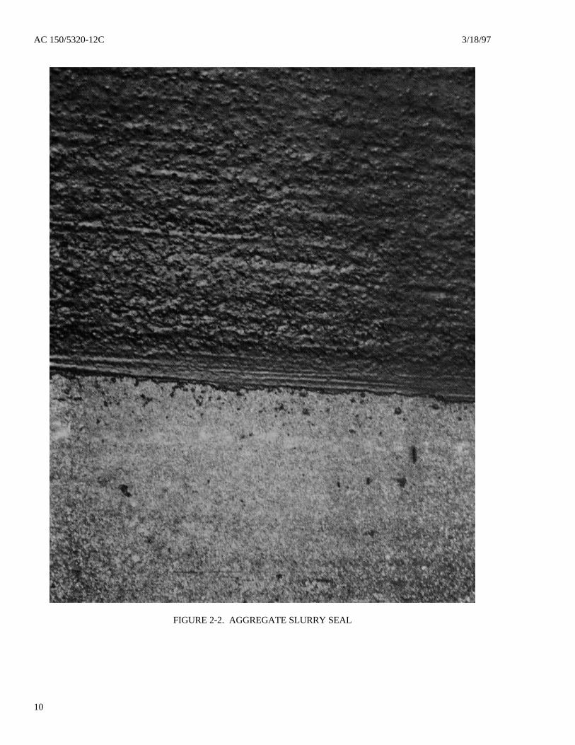
2-8. AGGREGATE SLURRY SEAL. Temporaryimprovement of skid-resistance for pavement surfacescan be gained by constructing an aggregate slurry seal,either gradation type II or type III, as given in thespecification in AC 150/5370-10. Aggregate slurryseats are recommended only as an interim measureuntil an overlay is constructed. This type ofconstruction is usually adequate for 2 to 5 years.Figure 2-2 shows a typical type II aggregate slurry seal.Experience has shown that slurry seals do not hold upwell in cold climates where snow removal occurs. Alife cycle cost analysis should be conducted todetermine the long term benefits.
2-9. CONSTRUCTION TECHNIQUES FOR PCCPAVEMENT. Several methods are available to thepaving contractor for constructing skid-resistant PCCpavement surfaces. When PCC pavement is still in theplastic condition, it is strongly recommended that sometype of textural finish be constructed in the pavementsurface prior to grooving. Such texturing can beaccomplished by using either a brush or broom finishor a heavy burlap drag finish. Wire combed or wiretined construction provides an excellent textural finishto the surface. Also, plastic grooves can be constructedin the pavement before it has hardened. For PCCpavements that have hardened, grooves can be saw cutin the pavement. The textural and groovingconstruction techniques are briefly described in thefollowing paragraphs. The basic constructionspecifications for PCC pavement are given in AC150/5370-10. Quality concrete is a prerequisite to theretention of pavement skid-resistance. The physicalproperties of the fine aggregates and effectiveness ofcuring are important factors in improving wearresistance.
2-10. TIMING AND CURING. Timing in applyingthe curing compound is as important as timing thefinal finishing operations to assure long lasting,nonskid pavement surface texture. The timing of thetexturing operation is critical because PCC pavementsrarely lose surface moisture evenly or set at a uniformrate, especially during warm weather pavingoperations. The best time to texture a PCC pavementduring construction is when the water spots have driedenough to reasonably hold the texture but before thedrier spots have dried too much to texture at all. Thisis one of the toughest decisions for the pavingcontractor. After texturing of the pavement surface hasbeen completed, immediate application of the curing
compound assures that the pavement surface will notlose water and cure too rapidly. If the pavement curestoo quickly, the ridges of mortar left by the finishingtechnique will not set properly and their durability willbe greatly reduced, resulting in a faster rate ofdiminishing skid-resistance. Therefore, extreme caremust be taken in this process to assure an effectivecure.
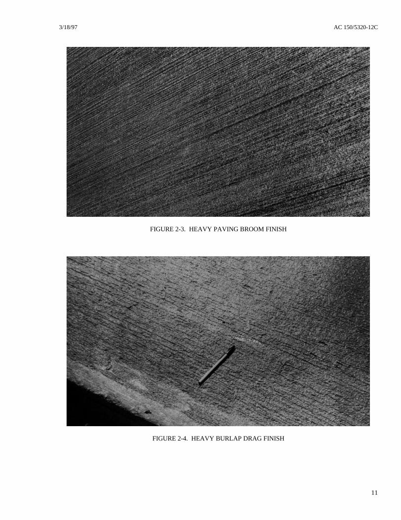
2-11. BRUSH OR BROOM FINISH. If thepavement surface texture is to be a type of brush orbroom finish, it should be applied when the watersheen has practically disappeared. The equipmentshould operate transversely across the pavementsurface, providing corrugations that are uniform inappearance and approximately 1/16 inch (1-1/2 mm)deep. It is important that the texturing equipment nottear or unduly roughen the pavement surface duringthe operation. Any imperfections resulting from thetexturing operation should be corrected immediatelyafter application before the concrete becomes too stiffto work. Figure 2-3 shows the texture formed by thebroom finish.
2-12. BURLAP DRAG FINISH. Burlap used totexture the pavement surface should be at least15 ounces/square yard (355 gm/square m). To producea rough textured surface, the transverse threads of theburlap should be removed from approximately 1 foot(0.3 m) of the trailing edge and grout should beallowed to accumulate and harden on the trailingburlap threads. A heavy buildup of grout on the burlapthreads produces the desired wide sweepinglongitudinal striations on the pavement surface. Theaggregate particles form the corrugations which shouldbe uniform in appearance and approximately 1/16 inch
AC 150/5320-12C 3/18/97
6
(1-1/2 mm) deep. A runway pavement constructedwith a burlap drag finish is shown in Figure 2-4.
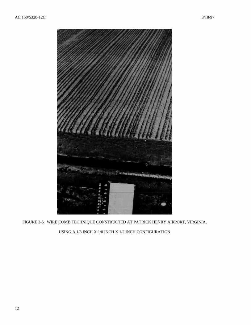
2-13. WIRE COMBING. The wire comb techniqueuses rigid steel wires to form a deep texture in theplastic concrete pavement. An excellent example ofthis method is the runway constructed at Patrick HenryAirport in Virginia, where the spacing of the ridges isapproximately 1/2 inch (13 mm) center to center (seeFigure 2-5). The spring steel wires which were usedhad an exposed length of 4 inches (100 mm), thicknessof 0.03 inch (0.7 mm), and width of 0.08 inch (2 mm).The wire comb equipment should provide grooves thatare approximately 1/8 inch x 1/8 inch (3 mm x 3 mm)spaced 1/2 inch (13 mm) center to center. It is notnecessary to provide preliminary texturing beforeconstructing the wire comb texture. Because of thecloseness of the spaced grooves, the preliminarytexturing of the remaining land areas would not be
effective. The wire comb technique should beconstructed over the full pavement width. Thistechnique is not to be confused with saw cut orplastic grooved runway pavements. Wire combing isa texturing technique and cannot be substituted for sawcut or plastic grooves because it does not preventaircraft from hydroplaning.
2-14. WIRE TINING. Flexible steel wires are used toform deep texture in the plastic concrete pavement.The flexible steel bands are 5 inches (125 mm) long,approximately 1/4 inch (6 mm) wide, and spaced1/2 inch (13 mm) apart. The appearance of thistechnique is quite similar to the wire comb method.This technique is not to be confused with saw cut orplastic grooved runway pavements. Wire tining is atexturing technique and cannot be substituted for sawcut or plastic grooved because it does not preventaircraft from hydroplaning.
Section 4. Runway Grooving
2-15. GENERAL GROOVING TECHNIQUES.Cutting or forming grooves in existing or newpavement is a proven and effective technique forproviding skid-resistance and prevention ofhydroplaning during wet weather. In existingpavement (both HMA and PCC), grooves must be sawcut; in new PCC pavement, grooves may be formedwhile the concrete is still plastic. Grooves in HMApavement must be saw cut whether new or existingpavement is to be treated.
2-16. DETERMINING NEED FOR GROOVING.Grooving of all runways, serving or expected to serveturbojet aircraft, is considered high priority safety workand should be accomplished during initialconstruction. Such existing runways without groovingshould be programmed as soon as practicable. Forother runways, the following factors should beconsidered:
a. Historical review of aircraft accidents andincidents related to hydroplaning at the airport.
b. Wetness frequency (review of annual rainfallrates and intensity).
c. Transverse and longitudinal grades, flatareas, depressions, mounds, or any other surfaceabnormalities that may impede water runoff.
d. Surface texture quality as to slipperinessunder dry or wet conditions. Polishing of aggregate,improper seat coating, inadequate micro-macrotexture,and contaminant buildup are some examples ofconditions that may cause the loss of surface friction.
e. Terrain limitations such as dropoffs at theends of the runway safety areas.
f. Adequacy of number and length of availablerunways.
g. Crosswind effects, particularly when lowfriction factors prevail at the airport.
h. The strength and condition of the runwaypavements at the facility.
2-17. SUITABILITY OF EXISTING PAVEMENTSFOR GROOVING. Existing pavements may havesurfaces that are not suitable for sawing grooves. Asurvey should be conducted to determine if an overlayor rehabilitation of the pavement surface is requiredbefore grooving.
a. Reconnaissance. A thorough survey shouldbe made of the entire width and length of the runway.Bumps, depressed areas, bad or faulted joints, andbadly cracked and/or spalled areas in the pavementshould not be grooved until such areas are adequatelyrepaired or replaced. To verify the structural condition
3/18/97 AC 150/5320-12C
7
of the pavement, tests should be taken in support of thevisual observations.
b. Tests. The strength and condition of therunway pavement should be evaluated and testedaccording to the procedures specified in ACs150/5320-6 and 150/5370-10. Future aircraft loadsand activity levels should be considered when makingthe evaluation. Core samples should be taken in HMApavement to determine stability. The AmericanSociety for Testing and Materials (ASTM) Standard D1559, Standard Test Method for Resistance to PlasticFlow of Bituminous Mixtures Using MarshallApparatus, provides methods for testing the resistanceto plastic flow of HMA pavements. Engineeringjudgment should be exercised when employing thesemethods in determining the stability readings. Thesetests are recommended to be used for guidance only.Other factors should be considered in determining howlong grooves will remain effective in HMA pavements,such as maximum operational pavement surfacetemperature, effective tire pressure, frequency ofbraking action in given areas, mix composition, andaggregate properties. If, in the judgment of the personevaluating the existing pavement, any of the aboveconditions are not met, the pavement should not begrooved.
2-18. OVERLAYS. If the evaluation shows that theexisting pavement is not suitable either because ofsurface defects or from a strength standpoint, anoverlay, flexible or rigid, will be required. The newoverlay may then be grooved according to theinstructions given in the following paragraphs:
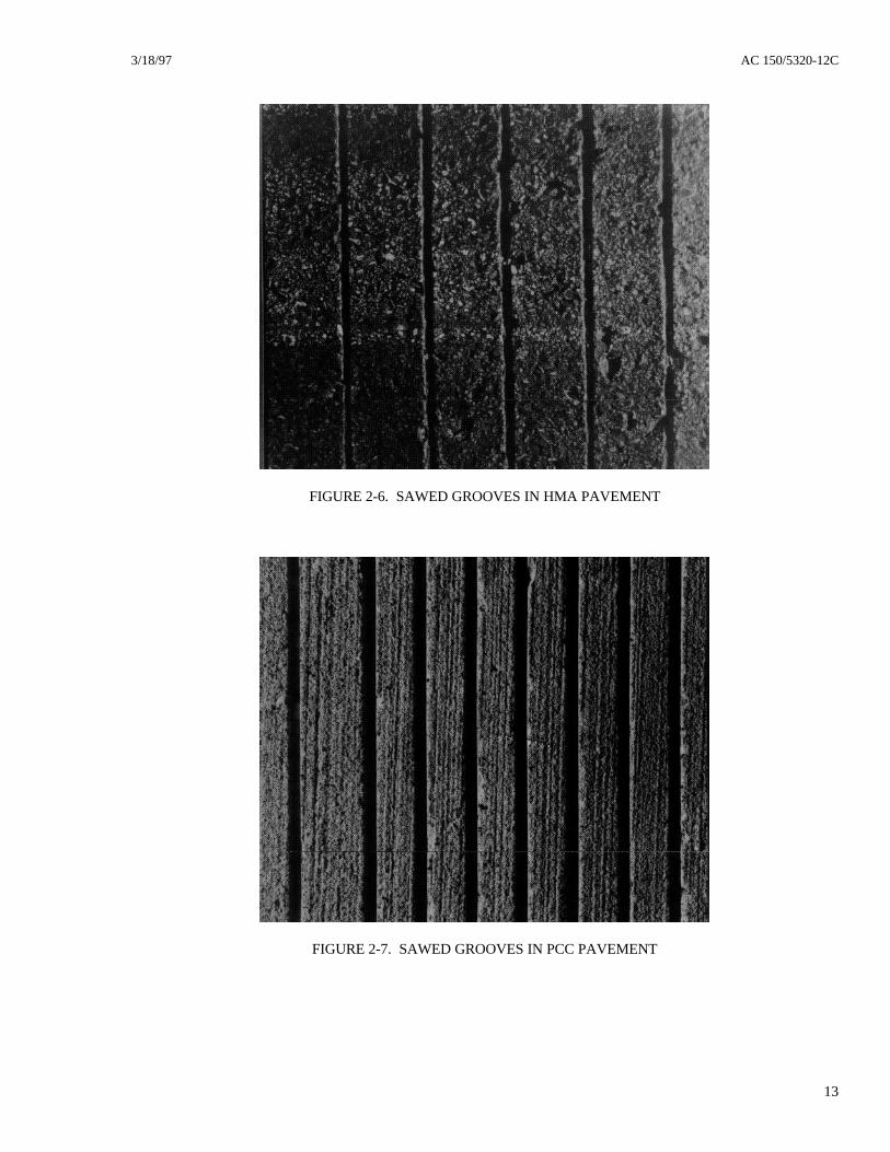
2-19. HMA PAVEMENT GROOVING.Construction specifications for grooving are given inparagraph 2-21. Grooving should not commence untilthe HMA pavement has sufficiently cured to preventdisplacement of the aggregate (usually 30 days).Figure 2-6 shows a saw-grooved HMA pavementsurface.
2-20. PCC Pavement Grooving. There are twoacceptable methods for grooving PCC pavements:plastic grooving and saw cut grooving.
a. Plastic Grooving.
(1) Vibrating Ribbed Plate. One method toform grooves in the concrete while in the plastic stateuses a vibrating ribbed plate attached to the bridge thatspans across the pavement slab. The plate is vibrated
to help redistribute the aggregate in the concrete. Thisprevents tearing and shearing as the plate proceedstransversely across the pavement slab. The groovesformed in the pavement are approximately 1/4 inch x1/4 inch (6 mm x 6 mm) width and depth, spaced1-1/2 inch (40 mm) center to center. Figure 2-8 showsthe grooving operations.
(2) Ribbed Roller. Another method uses aroller with protrusions or ribs which form the groovesin the plastic concrete. This method does not give thesame finish as the method using the vibrating ribbedplate. The roller is not vibrated and, therefore, doesnot consistently penetrate to the required depth of 1/4inch (6 mm). Figure 2-9 shows the results of thistechnique.
b. Saw Grooving. For existing or new PCCpavements that have hardened, transverse grooves canbe saw cut in the pavement. The timing should be asdirected by the engineer. Construction specificationsfor providing saw grooves in PCC pavements are givenin paragraph 2-21. Figure 2-7 shows a saw-groovedPCC pavement surface.
2-21. FAA SPECIFICATIONS FOR RUNWAYGROOVING.
a. THE FAA STANDARD GROOVECONFIGURATION IS 1/4 INCH (±1/16 INCH) INDEPTH BY 1/4 INCH (+1/16 INCH, -0 INCH) INWIDTH BY 1 1/2 INCH (- 1/8 INCH, + 0 INCH)CENTER TO CENTER SPACING).
THE FAA STANDARD GROOVECONFIGURATION IN METRICS IS 6 MM(±1.6 MM) IN DEPTH BY 6 MM (+1.6 MM, -0MM) IN WIDTH BY 38 MM (- 3 MM, + 0 MM)CENTER TO CENTER SPACING).
b. THE DEPTH OF 60 PERCENT ORMORE OF THE GROOVES SHALL NOT BELESS THAN 1/4 INCH (6 MM).
c. THE GROOVES SHALL BECONTINUOUS FOR THE ENTIRE RUNWAYLENGTH AND TRANSVERSE(PERPENDICULAR) TO THE DIRECTION OFAIRCRAFT LANDING AND TAKEOFFOPERATIONS.
d. THE GROOVES SHALL BETERMINATED WITHIN 10 FEET (3 M) OF THE
AC 150/5320-12C 3/18/97
8
RUNWAY PAVEMENT EDGE TO ALLOWADEQUATE SPACE FOR OPERATION OF THEGROOVING EQUIPMENT.
e. THE GROOVES SHALL NOT VARYMORE THAN 3 INCHES (8 CM) IN ALIGNMENTFOR 75 FEET (23 M) ALONG THE RUNWAYLENGTH, ALLOWING FOR REALIGNMENTEVERY 500 FEET (150 M) ALONG THERUNWAY LENGTH.
f. GROOVES SHALL NOT BE CLOSERTHAN 3 INCHES (8 CM) OR MORE THAN9 INCHES (23 CM) FROM TRANSVERSEJOINTS IN CONCRETE PAVEMENTS.
g. WHERE LIGHTING CABLES AREINSTALLED, GROOVING THROUGHLONGITUDINAL OR DIAGONAL SAW KERFSSHALL BE AVOIDED. Grooves may be continuedthrough longitudinal construction joints.
h. Extreme care must be exercised whengrooving near in-pavement light fixtures andsubsurface wiring. GROOVES SHALL BE SAWEDNO LESS THAN 6 INCHES (15 CM) AND NOMORE THAN 18 INCHES (46 CM) FROM IN-PAVEMENT LIGHT FIXTURES.
i. Bidding should be based on the square yardof the grooved area, using the two-dimensional methodof measure with no deduction for areas skipped next tojoints and fixtures as specified.
j. Clean-up is extremely important and shouldbe continuous throughout the grooving operations.
The waste material collected during the groovingoperation must be disposed of by flushing with water,by sweeping, or by vacuuming. If waste material isflushed, the specifications should stipulate thefollowing:
(1) Whether or not the airport owner orcontractor is responsible for furnishing water for clean-up operations.
(2) That the waste material should not beflushed into the storm or sanitary sewer system.
(3) That the waste material should not beallowed to drain onto the grass shoulders adjacent tothe runway or left on the runway surface. Failure toremove the material from all paved and shoulder areascan create conditions hazardous to aircraft operations.
a. IN ALL CASES, THE ENTIRE LENGTHOF THE PRIMARY RUNWAY WILL BEGROOVED. THE SECONDARY RUNWAYINTERSECTING THE PRIMARY RUNWAYSHALL BE SAW CUT IN A STEP PATTERN ASSHOWN IN FIGURE 2-10.
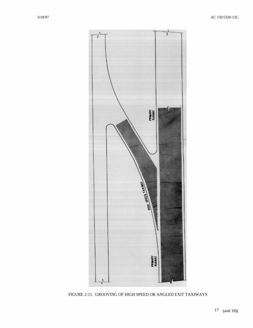
b. HIGH SPEED OR ANGLED EXITTAXIWAYS SHALL BE SAW CUT IN A STEPPATTERN AS SHOWN IN FIGURE 2-11. Sincegrooving machines vary in cutting width, it issuggested that the step pattern width start at theprojecting pavement edge, not exceeding 40 inches(102 cm) in width.
3/18/97 AC 150/5320-12C
9
FIGURE 2-1. EDGE VIEW OF PFC OVERLAY
AC 150/5320-12C 3/18/97
10
FIGURE 2-2. AGGREGATE SLURRY SEAL
3/18/97 AC 150/5320-12C
11
FIGURE 2-3. HEAVY PAVING BROOM FINISH
FIGURE 2-4. HEAVY BURLAP DRAG FINISH
AC 150/5320-12C 3/18/97
12
FIGURE 2-5. WIRE COMB TECHNIQUE CONSTRUCTED AT PATRICK HENRY AIRPORT, VIRGINIA,
USING A 1/8 INCH X 1/8 INCH X 1/2 INCH CONFIGURATION
3/18/97 AC 150/5320-12C
13
FIGURE 2-6. SAWED GROOVES IN HMA PAVEMENT
FIGURE 2-7. SAWED GROOVES IN PCC PAVEMENT
AC 150/5320-12C 3/18/97
14
FIGURE 2-8. PLASTIC GROOVING TECHNIQUE USING A VIBRATING RIBBED PLATE
3/18/97 AC 150/5320-12C
15
FIGURE 2-9. PLASTIC GROOVING TECHNIQUE USING A RIBBED ROLLER TUBE
AC 150/5320-12C 3/18/97
16
FIGURE 2-10. GROOVING INTERSECTIONS OF PRIMARY AND SECONDARY RUNWAYS
3/18/97 AC 150/5320-12C
(and 18)(17
FIGURE 2-11. GROOVING OF HIGH SPEED OR ANGLED EXIT TAXIWAYS
3/18/97 AC 150/5320-12C
19
CHAPTER 3. PAVEMENT EVALUATION
Section 1. Need for and Frequency of Evaluation
3-1. FRICTION DETERIORATION. Over time,the skid-resistance of runway pavement deterioratesdue to a number of factors, the primary ones beingmechanical wear and polishing action from aircrafttires rolling or braking on the pavement and theaccumulation of contaminants, chiefly rubber, on thepavement surface. The effect of these two factors isdirectly dependent upon the volume and type of aircrafttraffic. Other influences on the rate of deteriorationare local weather conditions, the type of pavement(HMA or PCC), the materials used in originalconstruction, any subsequent surface treatment, andairport maintenance practices.
Structural pavement failure such as rutting, raveling,cracking, joint failure, settling, or other indicators ofdistressed pavement can also contribute to runwayfriction losses. Prompt repair of these problems shouldbe undertaken as appropriate. Guidance on correctiveaction may be found in chapter 2 and AC 150/5380-6.
Contaminants, such as rubber deposits, dust particles,jet fuel, oil spillage, water, snow, ice, and slush, allcause friction loss on runway pavement surfaces.Removal and runway treatment for snow, ice, andslush are covered in AC 150/5200-30. The mostpersistent contaminant problem is deposit of rubberfrom tires of landing jet aircraft. Rubber depositsoccur at the touchdown areas on runways and can bequite extensive. Heavy rubber deposits can completelycover the pavement surface texture causing loss ofaircraft braking capability and directional control,particularly when runways are wet.
3-2. SCHEDULING PAVEMENTEVALUATIONS. The operator of any airport withsignificant jet aircraft traffic should schedule periodicfriction evaluations of each runway that accommodatesjet aircraft. These evaluations should be carried out inaccordance with the procedures outlined in eitherSection 2 or 3 of this chapter, depending upon theavailability to the airport operator of continuousfriction measuring equipment (CFME). Every runwayfor jet aircraft should be evaluated at least once eachyear. Depending on the volume and type (weight) oftraffic on the runways, evaluations will be needed morefrequently, with the most heavily used runwaysneeding evaluation as often as weekly, as rubberdeposits build up. Runway friction measurements take
time, and while tests are being conducted, the runwaywill be unusable by aircraft. Since this testing is nottime critical, a period should be selected whichminimizes disruption of air traffic. Airport operationsmanagement should work closely with air trafficcontrol, fixed base operations, and/or airlines.
3-3. MINIMUM FRICTION SURVEYFREQUENCY. Table 3-1 should be used as guidancefor scheduling runway friction surveys. This table isbased on an average mix of turbojet aircraft operatingon any particular runway. Most aircraft landing on therunway are narrow body, such as the DC-9, BAC-111,B-727, B-737, etc. A few wide body aircraft wereincluded in the mix. When any runway end has20 percent or more wide body aircraft (L-1011, B-747,DC- 10, MD-11, C-5, etc.) of the total aircraft mix, itis recommended that the airport operator should selectthe next higher level of aircraft operations in Table 3-1to determine the minimum survey frequency. Asairport operators accumulate data on the rate of changeof runway friction under various traffic conditions, thescheduling of friction surveys may be adjusted toensure that evaluators will detect and predict marginalfriction conditions in time to take corrective actions.
TABLE 3-1. FRICTION SURVEY FREQUENCY
NUMBER OF DAILYMINIMUM TURBOJETAIRCRAFT LANDINGS
PER RUNWAY END
MINIMUMFRICTION SURVEY
FREQUENCY
LESS THAN 15 1 YEAR16 TO 30 6 MONTHS31 TO 90 3 MONTHS91 TO 150 1 MONTH
151 TO 210 2 WEEKSGREATER THAN 210 1 WEEK
NOTE: Each runway end should be evaluatedseparately, e.g., Runway 18 and Runway 36.
3-4. SURVEYS WITHOUT CFME. Research hasshown that visual evaluations of pavement friction arenot reliable. An operator of an airport that does notsupport turbojet operations who suspects that a runwaymay have inadequate friction characteristics shouldarrange for testing by CFME. Visual inspections areessential, however, to note other surface condition
AC 150/5320-12C 3/18/97
20
inadequacies such as drainage problems, includingponding and groove deterioration, and structuraldeficiencies.
3-5. GROOVE DETERIORATION. Periodically,the airport operator should measure the depth andwidth of a runway's grooves to check for wear anddamage. When 40 percent of the grooves in therunway are equal to or less than 1/8 inch (3 mm) indepth and/or width for a distance of 1,500 feet (457 m),the grooves’ effectiveness for preventing hydroplaninghas been considerably reduced. The airport operatorshould take immediate corrective action to reinstate the1/4 inch (6 mm) groove depth and/or width.
3-6. MEASUREMENT OF PAVEMENTSURFACE TEXTURE. When a friction test
identifies a pavement surface with inadequate frictioncharacteristics, the cause, such as rubber accumulation,is often obvious. When the cause is not obvious, thefollowing guidance may be helpful in determining ifthe deficiency is a result of a deterioration in surfacetexture depth. Such deterioration may be caused byweather influences, wear/polishing effects of aircrafttraffic, and contaminants including but not limited torubber deposits. Visual inspections cannot be reliedupon to identify pavement surfaces with poor texture.Pavement texture depths can only be determined bydirect measurements. Even direct measurements maybe affected by the operator of the equipment, so theyshould be used as only part of an overall pavementfriction evaluation.
Section 2. CFME - General
3-7. GENERAL REQUIREMENTS FOR CFME.All airports with turbojet traffic should own or haveaccess to use of CFME. Not only is it an effective toolfor scheduling runway maintenance, it can also be usedin winter weather to enhance operational safety (seeAC 150/5200-30). Airports that have few turbojettraffic operations may be able to borrow the CFMEfrom nearby airports for maintenance use, shareownership with a pool of neighboring airports, or hirea qualified contractor.
3-8. FAA PERFORMANCE STANDARDS FORCFME. Appendix 3 contains the performancespecifications for CFME. These standards should beused by airport operators in procuring CFME andreplacement tires for the equipment.
3-9. FAA QUALIFIED PRODUCT LIST. Theequipment listed in Appendix 4 has been tested andmeets the FAA standards for CFME for use inconducting maintenance friction tests.
3-10. USE OF DECELEROMETER. Sincedecelerometers are not capable of providing continuousfriction measurements and do not give reliable resultson wet pavement surfaces, they are not approved forconducting runway maintenance surveys as discussedin this AC. However, the devices are approved forconducting friction surveys on runways during winteroperations (reference AC 150/5200-30).
3-11. FEDERAL FUNDING OF CFME. The Airportand Airway Improvement Act of 1982 (AAIA) includes
friction measuring equipment as an eligible item forairport development. However, before programming orprocuring this equipment, airport operators shouldcontact their FAA Regional or Airports District Officefor guidance.
3-12. TRAINING OF PERSONNEL. The success offriction measurement in delivering reliable frictiondata depends heavily on the personnel who areresponsible for operating the equipment. Adequateprofessional training on the operation, maintenance,and procedures for conducting friction measurementshould be provided either as part of the procurementpackage or as a separate contract with themanufacturer. Also, recurrent training is necessary forreview and update to ensure that the operatormaintains a high level of proficiency. Experience hasshown that unless this is done, personnel lose touchwith new developments on equipment calibration,maintenance, and operating techniques. A suggestedtraining outline for the manufacturers is given inAppendix 5. Airport personnel should be trained notonly in the operation and maintenance of the CFMEbut also on the procedures for conducting frictionsurveys. These procedures are provided in Section 4below. At airports where friction tests are performedless frequently than quarterly, and CFME is not usedfor winter operations, consideration should be given tohiring a qualified contractor to perform tests.
3-13. CALIBRATION. All CFME should be checkedfor calibration within tolerances given by themanufacturer before conducting friction surveys.
3/18/97 AC 150/5320-12C
21
CFME furnished with self-wetting systems should becalibrated periodically to assure that the water flow rateis correct and that the amount of water produced for
the required water depth is consistent and appliedevenly in front of the friction measuring wheel(s) forall test speeds.
Section 3. Conducting Friction Evaluations with CFME
3-14. PRELIMINARY STEPS. Frictionmeasurement operations should be preceded by athorough visual inspection of the pavement to identifydeficiencies as outlined in paragraph 3-4. Careful andcomplete notes should be taken not only of the CFMEdata but of the visual inspection as well. The airportoperator should assure that appropriatecommunications equipment and frequencies areprovided on all vehicles used in conducting frictionsurveys and that all personnel are fully cognizant ofairport safety procedures. Personnel operating theequipment should be fully trained and current in allprocedures. The CFME should be checked for accuratecalibration and the vehicle checked for adequatebraking ability.
3-15. LOCATION OF FRICTION SURVEYS ONTHE RUNWAY. The airport operator, whenconducting friction surveys on runways at 40 mph(65 km/h), should begin recording the data 500 feet(152 m) from the threshold end to allow for adequateacceleration distance. The friction survey should beterminated approximately 500 feet (152 m) from theopposite end of the runway to allow for adequatedistance to safely decelerate the vehicle. Whenconducting friction surveys at 60 mph (95 km/h), theairport operator should start recording the survey1,000 feet (305 km) from the threshold end andterminate the survey approximately 1,000 feet from theopposite end of the runway. Where travel beyond theend of the runway could result in equipment damage orpersonal injury, additional runway length should beallowed for stopping. The lateral location on therunway for performing the test is based on the type ofaircraft operating on the runway. Unless surfaceconditions are noticeably different on either side of therunway centerline, a test on one side of the centerlinein the same direction the aircraft lands should besufficient. However, when both runway ends are to beevaluated, vehicle runs can be made to record data onthe return trip (both ways).
The lateral location on the runway for performingfriction surveys is based on the type and/or mix ofaircraft operating on the runway:
a. Runways Serving Only Narrow BodyAircraft. Friction surveys should be conducted 10 feet(3 m) to the right of the runway centerline
b. Runways Serving Narrow Body and WideBody Aircraft. Friction surveys should be conducted10 and 20 feet (3 and 6 m) to the right of the runwaycenterline to determine the worst case condition. If theworst case condition is found to be consistently limitedto one track, future surveys may be limited to thistrack. Care should be exercised, however, to accountfor any future and/or seasonal changes in aircraft mix.
3-16. VEHICLE SPEED FOR CONDUCTINGSURVEYS. All of the approved CFME in Appendix 4can be used at either 40 mph (65 km/h) or 60 mph(95 km/h). The lower speed determines the overallmacrotexture/contaminant/drainage condition of thepavement surface. The higher speed provides anindication of the condition of the surface'smicrotexture. A complete survey should include testsat both speeds.
3-17. USE OF CFME SELF-WETTING SYSTEM.Since wet pavement always yields the lowest frictionmeasurements, CFME should routinely be used on wetpavement which gives the "worst case" condition.CFME is equipped with a self-wetting system tosimulate rain wet pavement surface conditions andprovide the operator with a continuous record offriction values along the length of the runway. Theattached nozzle(s) are designed to provide a uniformwater depth of 1 mm (0.04 inch) in front of the frictionmeasuring tire(s). This wetted surface producesfriction values that are most meaningful in determiningwhether or not corrective action is required.
3-18. FRICTION SURVEYS DURING RAINFALL.One limitation in using the self-wetting system on afriction measuring device is that it cannot by itselfindicate the potential for hydroplaning. Some runwayshave depressed areas which pond during periods ofmoderate to heavy rainfall. These areas may exceedconsiderably the water depth used by the self-wettingsystem of the friction measuring device. Therefore, it
AC 150/5320-12C 3/18/97
22
is recommended that the airport owner periodicallyconduct visual checks of the runway surface duringrainfall, noting the location, average water depth, andapproximate dimensions of the ponded areas. If theaverage water depth exceeds 1/8 inch (3 mm) over alongitudinal distance of 500 feet (152 m), thedepressed area should be corrected to the standardtransverse slope. If possible, the airport owner shouldconduct periodic friction surveys during rainfallthrough the ponded areas.
3-19. FRICTION LEVEL CLASSIFICATION. Munumbers (friction values) measured by CFME can beused as guidelines for evaluating the surface frictiondeterioration of runway pavements and for identifyingappropriate corrective actions required for safe aircraftoperations. Table 3-2 depicts the friction values forthree classification levels for FAA qualified CFMEoperated at 40 and 60 mph (65 and 95 km/h) testspeeds. This table was developed from qualificationand correlation tests conducted at NASA’s WallopsFlight Facility in 1989.
TABLE 3-2. FRICTION LEVEL CLASSIFICATION FOR RUNWAY PAVEMENT SURFACES
3-20. EVALUATION AND MAINTENANCEGUIDELINES. The following evaluation andmaintenance guidelines are recommended based on thefriction levels classified in Table 3-2. These guidelinestake into account that poor friction conditions for shortdistances on the runway do not pose a safety problemto aircraft, but long stretches of slippery pavement areof serious concern and require prompt remedial action.
a. Friction Deterioration Below theMaintenance Planning Friction Level (500 ft).When the average Mu value on the wet runway
pavement surface is less than the MaintenancePlanning Friction Level but above the MinimumFriction Level in Table 3-2 for a distance of 500 feet(152 m), and the adjacent 500 foot (152 m) segmentsare at or above the Maintenance Planning FrictionLevel, no corrective action is required. These readingsindicate that the pavement friction is deteriorating butthe situation is still within an acceptable overallcondition. The airport operator should monitor thesituation closely by conducting periodic frictionsurveys to establish the rate and extent of the frictiondeterioration.
3/18/97 AC 150/5320-12C
23
b. Friction Deterioration Below theMaintenance Planning Friction Level (1000 ft).When the averaged Mu value on the wet runwaypavement surface is less than the MaintenancePlanning Friction Level in Table 3-2 for a distance of1000 feet (305 m) or more, the airport operator shouldconduct extensive evaluation into the cause(s) andextent of the friction deterioration and take appropriatecorrective action.
c. Friction Deterioration Below theMinimum Friction Level. When the averaged Muvalue on the wet pavement surface is below theMinimum Friction Level in Table 3-2 for a distance of500 feet (152 m), and the adjacent 500 foot (152 m)segments are below the Maintenance Planning FrictionLevel, corrective action should be taken immediatelyafter determining the cause(s) of the frictiondeterioration. Before undertaking corrective measures,the airport operator should investigate the overallcondition of the entire runway pavement surface to
determine if other deficiencies exist that may requireadditional corrective action.
d. New Design/Construction Friction Levelfor Runways. For newly constructed runwaypavement surfaces (that are either saw cut grooved orhave a PFC overlay) serving turbojet aircraftoperations, the averaged Mu value on the wet runwaypavement surface for each 500 foot (152 m) segmentshould be no less than the New Design/ConstructionFriction Level in Table 3-2.
3-21. COMPUTER EVALUATION OF FRICTIONTEST DATA. A manual evaluation of friction testdata as required by the criteria above can be tediousand prone to human error. An IBM PC-compatiblecomputer program which performs this evaluation isavailable free of charge. The computer program maybe downloaded from the FAA Airports Internet website at http://www.faa.gov/arp/software.htm.
Section 4. Conducting Texture Depth Measurements
3-22. RECOMMENDED TESTING. When frictionvalues meet the criteria in paragraphs 3-20.(a), 3-20.(b), and 3-20.(c), no texture depth measurementsare necessary. When friction values do not meet thecriteria in paragraphs 3-20.(a), 3-20.(b), or 3-20.(c),and the cause is not obvious (e.g. rubber deposits), theairport operator should perform texture depthmeasurements.
3-23 RECOMMENDED TEXTURE DEPTHS.
a. Newly Constructed Pavements. Therecommended average texture depth to provide goodskid-resistance for newly constructed concrete andasphalt pavements is 0.045 inch (1.14 mm). A lowervalue indicates a deficiency in macrotexture that willrequire correction as the surface deteriorates.
b. Existing Pavements.
(1) When the average texture depthmeasurement in a runway zone (i.e., touchdown,midpoint, and rollout) falls below 0.045 inch(1.14 mm), the airport operator should conduct texturedepth measurements each time a runway frictionsurvey is conducted.
(2) When the average texture depthmeasurement in a runway zone is below 0.030 inch(0.76 mm) but above 0.016 inch (0.40 mm), the airportoperator should initiate plans to correct the pavementtexture deficiency within a year.
(3) When the average texture depthmeasurement in a runway zone (i.e., touchdown,midpoint, and rollout) falls below 0.010 inch(0.25 mm), the airport operator should correct thepavement texture deficiency within 2 months.
c. Retexturing. Retexturing of the pavementsurface should improve the average texture depth to aminimum of 0.030 inch (0.76 mm).
3-24. LOCATION OF MEASUREMENTS. Groovedepths are never included in texture depthmeasurements. For grooved runway pavements,texture depth measurements should always be locatedin nongrooved areas, such as near transverse joints orlight fixtures, but as close as possible to heavilytrafficked areas.
3-25. TEST METHODS. A minimum of three texturedepth measurements should be taken in any area notedas deficient. More measurements should be takenwhen obvious textural changes in the pavement surface
AC 150/5320-12C 3/18/97
24
are observed. An average texture depth should becomputed for each area. Descriptions of the equipmentand methods used and the computations involved indetermining texture depths are as follows:
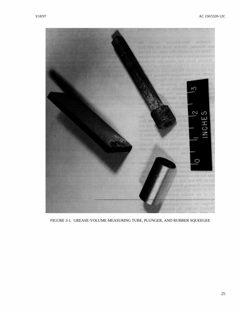
a. Equipment. The NASA Grease SmearMethod is used to determine the macrotexture of thepavement surface by measuring the average distancebetween the peaks and valleys in the pavement texture.This method cannot be used to evaluate the pavementmicrotexture. On the left in Figure 3-1 is shown thetube which is used to measure the 1 cubic inch (15 cc)volume of grease. On the right is shown the tight-fitting plunger which is used to expel the grease fromthe tube, and in the center is shown the rubbersqueegee which is used to work the grease into thevoids in the runway surface.
The sheet rubber on the squeegee is cemented to apiece of aluminum for ease in use. Any generalpurpose grease can be used. As a convenience in theselection of the length of the measuring tube, Figure 3-2 gives the relation between the tube inside diameterand tube length for an internal tube volume of onecubic inch (15 cu cm). The plunger can be made ofcork or other resilient material to achieve a tight fit inthe measuring tube.
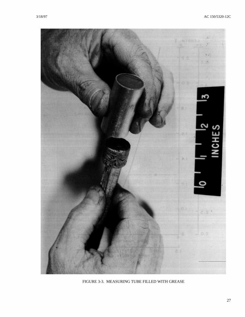
b. Measurement. The tube for measuring theknown volume of grease is packed full with a simpletool, such as a putty knife, with care to avoid entrappedair, and the ends are squared off as shown inFigure 3-3. A general view of the texture measurementprocedure is shown in Figure 3-4. The lines of maskingtape are placed on the pavement surface about 4 inches(10 cm) apart. The grease is then expelled from themeasuring tube with the plunger and depositedbetween the previously placed lines of masking tape. Itis then worked into the voids of the runway pavementsurface with the rubber squeegee, with care that nogrease is left on the masking tape or the squeegee. Thedistance along the lines of masking tape is thenmeasured and the area that is covered by the grease iscomputed.
3-26. COMPUTATION. After the area is completed,the following equations are used to calculate theaverage texture depth of the pavement surface:
Texture depth (inches) =Volume of Grease (cu. in.) Area Covered by Grease (sq. in.)
Average Texture Depth = Sum of individual TestsTotal Number of Tests
3/18/97 AC 150/5320-12C
25
FIGURE 3-1. GREASE-VOLUME MEASURING TUBE, PLUNGER, AND RUBBER SQUEEGEE
AC 150/5320-12C 3/18/97
26
FIGURE 3-2. MEASURING TUBE DIMENSIONS TO MEASURE
ONE CUBIC INCH OR FIFTEEN CUBIC CENTIMETERS
3/18/97 AC 150/5320-12C
27
FIGURE 3-3. MEASURING TUBE FILLED WITH GREASE
AC 150/5320-12C 3/18/97
28
FIGURE 3-4. ILLUSTRATION OF APPARATUS USED IN GREASE APPLICATION TECHNIQUE FORMEASURING PAVEMENT SURFACE TEXTURE DEPTH
3/18/97 AC 150/5320-12C
29
CHAPTER 4. MAINTAINING HIGH SKID-RESISTANCE
Section 1. Maintenance Considerations
4-1. NEED FOR MAINTENANCE. As trafficmechanically wears down microtexture andmacrotexture and as contaminants build up on runwaypavements, friction will decrease to a point wheresafety may be diminished. At joint use airports, wherehigh numbers of military aircraft operations occur, theventing of excess fuel can lead to serious loss offriction by either causing contaminant buildup or an oilfilm on the pavement surface. Also, fog seal treatmentof HMA surfaces can substantially reduce thepavement's coefficient of friction during the first yearafter application. Surfaces which already havemarginally acceptable friction can becomeunacceptable when given this type of surface treatment.
When the measured coefficient of friction valuesapproach or drop below the Maintenance PlanningLevel as shown in Table 3-2 in chapter 3. Table 4-1may be used as a tool for budgeting for and schedulingappropriate and timely maintenance for removal ofcontaminants and restoration of good frictioncharacteristics. As stated in chapter 3, the averageaircraft mix was based on mostly narrow body aircraftwith a few wide body aircraft operations included.Rubber accumulation is dependent on the type andfrequency of aircraft landing operations; e.g., weight of
aircraft, the number of wheels that touchdown on thesurface, climate, runway length, and runwaycomposition. When more than 20 percent of the totalaircraft mix landing on any one runway end are widebody aircraft, it is recommended that the airportoperator select the next higher level of aircraftoperations in Table 4-1 to determine the rubberremoval frequency. Experience and the use of CFMEwill allow the airport operator to develop a schedulespecific to each runway.
TABLE 4-1. RUBBER DEPOSITREMOVAL FREQUENCY
NUMBER OR DAILYTURBOJET AIRCRAFT
LANDING PER RUNWAYEND
SUGGESTEDRUBBER DEPOSIT
REMOVALFREQUENCY
LESS THAN 15 2 YEARS16 TO 30 1 YEAR31 TO 90 6 MONTHS91 TO 150 4 MONTHS
151 TO 210 3 MONTHSGREATER THAN 210 2 MONTHS
Note: Each runway end should be evaluatedseparately, e.g. Runway 18 and Runway 36.
Section 2. Methods for Removing Contaminants
4-2. RECOMMENDED CONTAMINANTREMOVAL TECHNIQUES. Several methods areavailable for cleaning rubber deposits, othercontaminants, and paint markings from runwaysurfaces. They include high pressure water, chemical,high velocity impact, and mechanical grinding. Afterthe contaminants have been removed from the runwaysurface by any of these methods, the airport operatorshould conduct friction measurements to assure thatthe Mu values have been restored to within 10 percentof those on the uncontaminated center portion of therunway and that both measurements are well withinthe acceptable friction levels for safe aircraftoperations. The effectiveness of rubber depositremoval procedures cannot be evaluated by visualinspection. It is highly recommended that rubberdeposit removal contracts base payments on final testsby CFME. A brief description follows for each of the
contaminant removal techniques. None of thetechniques should be used unless the runway is free ofstanding water, snow, slush, and/or ice. Also,chemical or water impact removal methods should notbe used if there is a danger of the fluids freezing.
The ultimate success of any method will depend on theexpertise of the equipment operator. Results can varyfrom completely ineffective to a situation where allrubber deposits are removed, but the underlyingpavement is significantly damaged. It is recommendedthat airport operators require that a test section becleaned by the contractor to demonstrate that rubberdeposits will be removed without damage to theunderlying pavement.
a. Removal by High Pressure Water. Aseries of high pressure water jets is aimed at the
AC 150/5320-12C 3/18/97
30
pavement to blast the contaminants from the surface,allowing the water to transport the rubber particles tothe edge of the runway. The technique is economical,environmentally clean, and effectively removesdeposits from the pavement surface with minimaldowntime to the airport operator. High-pressure waterblasting also may be used to improve the surfacetexture of smooth pavements. Water pressures usedvary significantly. There are so many other parametersthat vary from one contractor's equipment to another,however, that the pressure of the water used is not agood indication of the potential for either effectivenessor pavement damage. The airport operator should relyon the contractor's experience, demonstrated expertise,and references.
b. Removal by Chemicals. Chemical solventshave been used successfully for removal ofcontaminants on both PCC and HMA runways. Anychemicals used on runways must meet Federal, state,and local environmental requirements. For removal ofrubber deposits on PCC runways, chemicals are usedwhich have a base of cresylic acid and a blend ofbenzene, with a synthetic detergent for a wetting agent.For removal of rubber deposits on HMA runways,alkaline chemicals are generally used. Because of thevolatile and toxic nature of such chemicals, extremecare must be exercised during and after application. Ifthe chemicals remain on the pavement too long, thepainted areas on the runway and possibly the surfaceitself could be damaged. It is also very important todilute the chemical solvent that is washed off thepavement surface so that the effluent will not harmsurrounding vegetation or drainage systems or pollutenearby streams and wildlife habitats. Detergents madeof metasilicate and resin soap can be used effectively to
remove oil and grease from PCC runway surfaces. ForHMA pavements, an absorbent or blotting materialsuch as sawdust or sand combined with a rubberalkaline degreaser may be used.
c. High Velocity Impact Removal. Thismethod employs the principle of throwing abrasiveparticles at a very high velocity at the runwaypavement surface, thus blasting the contaminants fromthe surface. Additionally, the machine that performsthis operation can be adjusted to produce the desiredsurface texture, if so required. The abrasive ispropelled mechanically from the peripheral tips ofradial blades in a high speed, fan like wheel. Theentire operation is environmentally clean in that it isself-contained; it collects the abrasive particles, loosecontaminants, and dust from the runway surface; itseparates and removes the contaminants and dust fromthe abrasive; and it recycles the abrasive particles forrepetitive use. The machine is very mobile and can beremoved rapidly from the runway if required by aircraftoperations.
d. Mechanical Removal. Mechanical grindingthat employs the corrugating technique has beensuccessfully used to remove heavy rubber deposits fromboth PCC and HMA runways. It has also been used toremove high areas such as bumps on pavementsurfaces or at joints where slabs have shifted or faulted.This method greatly improves the pavement surfacefriction characteristics. Pavement surfaces that areeither contaminated (rubber buildup or bleeding) orworn can have their surface friction coefficient greatlyincreased by a thin milling operation. This techniqueremoves a surface layer between 1/8 and 3/16 inch(3.2 and 4.8 mm) in depth.
3/18/97 AC 150/5320-12CAppendix 1
1 (and 2)
APPENDIX 1. QUALIFICATION PROCESS FOR CFME
1. FRICTION EQUIPMENT CORRELATIONPROGRAM. From 1982 through 1985, the FAAconducted a series of tests to determine the correlationof the Mu Meter with the Saab Friction Tester,Skiddometer, and the Runway Friction Tester, usingthe equipments' self-wetting systems on dry pavementsurfaces at NASA's Wallops Right Facility.Correlation values were established for the SaabFriction Tester, the Runway Friction Tester, theSkiddometer, and the Mu Meter. Reference Appendix2, Report No. DOT/FAA/AS-90-1, which shows theresults of the correlation trials conducted at NASA’sWallops Flight Facility in August 1989. Additionaldevices have since been found to meet FAAspecifications. All devices found to meet FAAspecifications are listed in appendix 4.
2. FRICTION/SPEED RELATIONSHIPS FORPAVEMENT SURFACES. The relationship of speedto friction has a profound influence on aircraft brakingperformance when pavements have little or nomicrotextural properties. According to the UnifiedMechanism of Rubber/Pavement Friction, the adhesioncomponent of friction, which is governed mainly by theshear force between the tire and the pavement surface,is high at lower speeds of up to about 100 mph. Therubber couples well with a good microtextured surfaceto provide high friction at the lower speeds. At speedsover 100 mph, the hysteresis component of frictiongoverns. This component is the effect of damping orreacting elastic pressure of rubber when deformedaround aggregate particles. The deformation isproduced best by good macrotextured surfaces. Inessence, the Unified Mechanism simply states that agood macro/microtexture surface will provide relativelyhigh friction and flat friction speed gradient on wetpavement surfaces. As speed increases, macrotexturedsurfaces will provide good drainage to keep thehydrodynamic pressure low and the tire in contact withthe pavement surface for a low friction/speed gradient.However, a poor macrotextured pavement surfacecannot provide sufficient drainage for goodtire/pavement contact. Thus, the friction speedgradient decreases rapidly.
The relationship of the friction/speed gradient wasdetermined at NASA's Wallops Flight Facility byconducting friction surveys on several types ofpavement surfaces that represented a wide range of
friction values at speeds of 20, 40, 60, and 80 mph.Testing operational runways at 20 mph is notpracticable, since a test of a 10.000' runway would takeapproximately 6 minutes. Likewise, the distancerequired to accelerate to and decelerate from 80 mphwould preclude testing most of a typical touchdownzone. Therefore, a compromise is made and tests areconducted at only two speeds, 40 and 60 mph. Thesetwo speeds will provide an adequate representation ofthe friction/speed gradient for the various texturedpavement surfaces encountered.
3. DEVELOPMENT OF PERFORMANCESPECIFICATION FOR FRICTION EQUIPMENT.The following paragraphs discuss the qualificationprocess used to develop the performance specificationfor the friction equipment and friction measuring tires.
a. Development of the Friction EquipmentPerformance Specification. To qualify for Federalfunds, friction equipment performance standards hadto be developed. Friction tests were conducted atNASA's Wallops Flight Facility to develop theperformance specification for friction measuringequipment. The specification was developed to assurethe airport operator that the friction measuringequipment would perform with reliability andconsistency on all types of pavement surfaceconditions.
b. Development of the Tire PerformanceSpecification. Prior to 1989, only one frictionmeasuring tire was available for friction measuringdevices. During 1988, the E-17 committee of ASTMrequested the FAA to conduct tire performance tests ontwo tires manufactured according to ASTMspecifications E-524, Specification for StandardSmooth Tire for Pavement Skid-resistance Tests, andE-670, Standard Test Method for Side Force Frictionon Paved Surfaces Using the Mu-Meter, and comparethese tires with the performance of the then FAAstandard tire. A tire performance specification wasdeveloped for the test program. The tests wereconducted at NASA's Wallops Flight Facility inAugust 1989. The tires are manufactured in the UnitedStates by the McCreary Tire & Rubber Company ofIndiana, Pennsylvania and Dico Tire, Inc. of Clinton,Tennessee.
3/18/97 AC 150/5320-12CAppendix 2
1
APPENDIX 2. RELATED READING MATERIAL
1. The latest issues of the following free publicationsmay be obtained from the U.S. Department ofTransportation, Warehousing and SubsequentDistribution Section, SVC-121.23, Washington, DC20590. AC 00-2, Advisory Circular Checklist, currentedition, contains the listing of all current issues ofcirculars and changes thereto.
a. AC 150/5200-28, Notices to Airman(NOTAMS) for Airport Operators.
b. AC 150/5200-30, Airport Winter Safety andOperation.
c. AC 150/5320-6, Airport Pavement Designand Evaluation.
2. Copies of the following publications may beobtained from the Superintendent of Documents, U.S.Government Printing Office, Washington, DC 20402.Send check or money order with your request madepayable to the Superintendent of Documents in theamount stated. No C.O.D. orders are accepted.
a. AC 150/5300-13, Airport Design ($15.00).
b. AC 150/5370-10, Standards for SpecifyingConstruction of Airports, current edition ($18.00).
c. AC 150/5380-6, Guidelines and Proceduresfor Maintenance of Airport Pavements ($7.00).
3. Copies of Part 15, Road, Paving, BituminousMaterials, Skid-resistance, and Skid-resistance ofHighway Pavements, STP 530, may be obtained fromthe American Society For Testing and Materials, 1916Race Street, Philadelphia, Pennsylvania 19103.
4. Copies of the following publications may beobtained from the National Technical InformationService, Springfield, Virginia 22151.
a. Pavement Grooving and Traction Studies,Report No. NASA SP-5073, 1969.
b. A Comparison of Aircraft and GroundVehicle Stopping Performance on Dry, Wet, Flooded,Slush, and Ice-covered Runways, Report No. NASATN D-6098, November 1970.
c. Runway Friction Data for 10 Civil Airportsas Measured with a Mu Meter and Diagonal BrakedVehicle, Report No. FAA-RD-72-61, July 1972.
d. Effects of Pavement Texture on Wet RunwayBraking Performance, Report No. NASA TN D-4323,January 1969.
e. Porous Friction Surface Courses, ReportNo. FAA-RD-73-197, February 1975.
f. Laboratory Method for Evaluating Effect ofRunway Grooving on Aircraft Tires, Report No. FAA-RD-74-12, March 1974.
g. Investigation of the Effects of RunwayGrooves on Wheel Spin-up and Tire Degradation,Report No. FAA-RD-71-2, April 1971.
h. Environmental Effects on Airport PavementGroove Patterns, Report No. FAA-RD-69-37, June1969.
i. The Braking Performance of an Aircraft Tireon Grooved Portland Cement Concrete Surfaces,Report No. FAA-RD-80-78, January 1981.
j. Braking of an Aircraft Tire on Grooved andPorous Asphaltic Concrete, Report No. DOT-FAA-RD-82-77, January 1983.
k. Analytical and Experimental Study ofGrooved Pavement Runoff, Report No. DOT-FAA-PM-83/84, August 1983.
l. Surveys of Grooves in Nineteen BituminousRunways, Report No. FAA-RD-79-28, February 1979.
m. Modified Reflex-Percussive Grooves forRunways, Report No. DOT-FAA-PM-82-8, March1984.
n. Reliability and Performance of FrictionMeasuring Tires and Friction Equipment Correlation,Report No. DOT/FAA/AS-90-1, March 1990.
5. Copies of MS-16, Asphalt in PavementMaintenance, may be obtained from the AsphaltInstitute Building, College Park, Maryland 20740.
AC 150/5320-12C 3/18/97Appendix 2
2
6. Copies of Maintenance Practices for ConcretePavements, may be obtained from the Portland CementAssociation, Old Orchard Road, Skokie, Illinois 60076.
7. Copies of the following publications may beobtained from the Highway Research Board, NationalAcademy of Sciences, 2101 Constitution Avenue,Washington, D.C. 20418.
a. Skid-resistance, National CooperativeHighway Research Program (NCHRP) Synthesis ofHighway Practice 14, 1972.
b. Pavement Rehabilitation - Materials andTechniques, National Cooperative Highway ResearchProgram (NCHRP) Synthesis of Highway Practice 9,1972.
c. Factors Affecting Skid-resistance and Safetyof Concrete Pavements, Special Report No. 101, 1969.
d. Road Surface Texture and the Slipperiness ofWet Roads, Record No. 214, 1968.
e. Pilot Field Study of Concrete PavementTexturing Methods, Record No. 389, 1972.
f. Prediction of Skid-resistance Gradient andDrainage Characteristics of Pavements, RecordNo. 131, 1966.
g. Standard Nomenclature and Definitions forPavement Components and Deficiencies, SpecialReport No. 113, 1970.
h. Development of Specifications for Skid-Resistant Asphalt Concrete, Record No. 396, 1972.
i. Skid-resistance of Screenings for Seal Coats,Record No. 296, 1968.
8. Copies of the following technical bulletins may bepurchased from the American Concrete PavingAssociation, Suite 490, 3800 N. Wilke Rd., ArlingtonHeights, Illinois, 60004-1268.
a. Texturing of Concrete Pavements, BulletinNo. 1.
b. Interim Recommendations for theConstruction of Skid-Resistant Concrete Pavement,Bulletin No. 6.
c. Guideline for Texturing of Portland CementConcrete Highway Pavements, Bulletin No. 19.
9. Copies of Evaluation of Two Transport Aircraftand Several Ground Test Vehicle FrictionMeasurements Obtained for Various Runway SurfaceTypes and Conditions, NASA Technical Paper 2917,February 1990, may be obtained from NASA, underthe Code NTT-4, Washington, DC 20546-0001.
10. Copies of ASTM Specifications can be obtainedfrom ASTM, 1916 Race Street, Philadelphia,Pennsylvania 19103.
3/18/97 AC 150/5320-12CAppendix 3
1
APPENDIX 3. PERFORMANCE SPECIFICATIONS FOR CFME
1. FRICTION EQUIPMENT PERFORMANCESTANDARD. The friction measuring equipment maybe self-contained or towed. If towed, the tow vehiclewill be considered an integral part of the device. Thevehicles and/or trailers shall meet all applicableFederal and state laws and/or regulations for vehiclesand/or trailers for use on public highways. The sideforce friction measuring device, the Mu Meter, shallmeet the Standard Test Method given in ASTM E 670.The Standard Test Method for the fixed brake slipdevices is under preparation by the ASTM Committee.
a. The Friction Measuring Equipment shalldo the following:
(1) provide fast, continuous, accurate, andreliable friction measurements for the entire length ofthe runway, less the differences required foraccelerating and decelerating the vehicle at the runwayends.
(2) be designed to sustain rough usage andstill function properly and provide efficient and reliablemethods of equipment calibration.
(3) be capable of automatically providingthe operator with a selection of average friction valuesfor both a 500 foot (150 m) and one-third segment ofrunway length. In addition, it shall be capable ofproviding data, whereby, the average friction value forany length of runway can be manually calculated.
(4) be capable of producing a permanenttrace of friction measurements versus pavement lengthat a scale of at least one inch (25 mm) equals 300 feet(90 m).
(5) be capable of consistently repeatingfriction averages throughout the friction range on alltypes of pavement surfaces. Friction averages for each500 foot (150 m) segment located on the pavementsurface must be within a confidence level of95.5 percent, or two standard deviations of ±.06 Munumbers.
(6) contain a self-wetting system thatdistributes water in front of the friction measuringwheel(s) at a uniform depth of 0.04 inch (1 mm). Themanufacturer shall provide documentation to show thatthe flow rate is within a tolerance of ±10 percent forboth test speeds.
(7) be able to conduct friction surveys atspeeds of 40 and 60 mph (65 and 95 km/hr), within atolerance of ±3 mph (±5 km/hr).
(8) include a complete set of the latestoperation and maintenance manuals includingguidelines for training airport personnel. The trainingmanuals shall include the current copy of this AC.
(9) have electronic instrumentation (solid-state electronics), including a keyboard for data entry,that will enhance the information gathering andanalysis capability of the equipment, and provide theoperator more convenience in equipment operation andperformance. The information gathered during afriction survey should be stored in an internalmicroprocessor memory and be readily visible to theoperator of the vehicle. This will allow for theexamination of data, printouts, and calculation ofaverage friction values over all or any portion of thetest run. Each printout of the chart produced by themicroprocessor unit shall include the followingrecorded information: runway designation and date;time of friction survey; a continuous trace of thefriction values obtained for the entire runway lengthminus the acceleration/deceleration distances; printedmarks depicting each 100 foot (30 m) increment of therunway length so easy reference can be made by theoperator in identifying specific areas on the runwaypavement surface; average friction value for 500 foot(150 m) and one-third segments of the runway lengthas preselected by the operator; and average vehiclespeed for that segment.
b. The vehicle shall:
(1) be able to conduct friction surveys atspeeds of 40 and 60 mph (65 and 95 km/hr), within atolerance of ±3 mph (±5 km/hr). The vehicle, whenfully loaded with water, shall be capable of acceleratingto these speeds within 500 and 1000 feet (150 and300 m) from the starting position, respectively.
(2) be equipped with electronic speedcontrol.
(3) conform to the requirements of AC150/5210-5, Painting, Marking, and Lighting ofVehicles Used on an Airport, for airfield servicevehicles.
AC 150/5320-12C 3/18/97Appendix 3
2
(4) be equipped with transceiver(s)necessary for communication with airport operationsand air traffic control.
(5) be equipped with a water tankconstructed of strong lightweight material, of sufficientcapacity to complete a friction survey on a 14,000 foot(4,267 m) runway in one direction and all necessaryappurtenances to deliver the required water flow rate tothe friction measuring wheel(s).
(6) be equipped with appropriate heavy dutyshock absorbers and heavy duty suspension toadequately handle imposed loads.
(7) be equipped with a device that willregulate the water flow within the confines of thevehicle near the driver's position. Where flowregulation is automatic, no device is required in thevehicle.
(8) be equipped with internally controlledspot lights on each side of the vehicle. For trailer
mounted equipment, the tow vehicle shall also beequipped with at least two floodlights mounted suchthat the friction measuring device and rear portion ofthe tow vehicle is illuminated to a level of at least20 foot-candles within an area bounded by lines 5 feet(2 m) on either side of the friction measuring deviceand 5 feet (2 m) in front of and behind the frictionmeasuring device.
(9) be equipped with an air conditionerwhen specified by the purchaser.
2. TIRE PERFORMANCE STANDARD. Thefriction measuring equipment shall be furnished withmeasuring tires which are designed for use inconducting friction surveys and which meet ASTMstandard E670, E-5551, or E-1844, as appropriate.Nonribbed (blank) tire(s) shall be used to eliminate theeffect of tire tread wear and provide greater sensitivityto variations in pavement surface texture. The tiresshall be furnished with split rims and the tubes shallhave curved valve stems. The manufacturer of thefriction equipment shall provide the airport user with acalibrated pressure dial gauge.
NORSEMETERP.O. Box 42Olav Ingstads vei 31351 RudNORWAY
RUNAR RUNWAY ANALYSER AND RECORDER+47 67 15 17 00
FAX +47 67 15 17 01
3/18/97 AC 150/5320-12CAppendix 5
1 (and 2)
APPENDIX 5. TRAINING REQUIREMENTS OUTLINE FOR CFME
1. GENERAL DISCUSSION. The followingparagraph lists the major items which should beconsidered in developing a training program for airportpersonnel responsible for operating and maintainingCFME. Whenever a major change in equipmentdesign occurs, the training and instruction manualsshould be revised. A document titled Training andInstruction Manual should always be provided to theairport personnel by the manufacturer and keptupdated.
2. TRAINING REQUIREMENTS OUTLINE.
a. Classroom Instruction.
(1) Purpose of Training Program.
(2) General Discussion on Pertinent FederalAviation Regulations.
(3) General Discussion on Pertinent ACs.
(4) General Discussion on Pertinent ASTMStandards.
(5) General Overview of Program.
(6) Review of Requirements inAC 150/5320-12.
(i) Coefficient of Friction Definition.
(ii) Factors Affecting FrictionConditions.
(iii) ASTM Standards for CFME.
(iv) ASTM Standards for FrictionMeasuring Tires.
(v) Operation of CFME.
(vi) Programming the Computer forFAA and ICAO Formats.
(vii) Maintenance of CFME.
(viii) Procedures for Reporting FrictionNumbers.
(ix) Preparation and Dissemination ofNOTAMS.
(7) Orientation to the Calibration, Operation,and Maintenance of CFME.
b. Field Experience. Operation andMaintenance of CFME.
c. Testing. Solo Test and Written Examinationon All Items Covered in Course.