20
GE Oil & Gas 1566 & 1566-2 Models Consolidated* Hydroset Testing Device for Setting Safety Valves Maintenance Manual GE Data Classification : Public
GE Oil & Gas
1566 & 1566-2 ModelsConsolidated* Hydroset Testing Device for Setting Safety Valves Maintenance Manual
GE Data Classification : Public

2 | GE Oil & Gas © 2015 General Electric Company. All rights reserved.
THESE INSTRUCTIONS PROVIDE THE CUSTOMER/OPERATOR WITH IMPORTANT PROJECT-SPECIFIC REFERENCE INFORMATION IN ADDITION TO THE CUSTOMER/OPERATOR’S NORMAL OPERATION AND MAINTENANCE PROCEDURES. SINCE OPERATION AND MAINTENANCE PHILOSOPHIES VARY, GE (GENERAL ELECTRIC COMPANY AND ITS SUBSIDIARIES AND AFFILIATES) DOES NOT ATTEMPT TO DICTATE SPECIFIC PROCEDURES, BUT TO PROVIDE BASIC LIMITATIONS AND REQUIREMENTS CREATED BY THE TYPE OF EQUIPMENT PROVIDED.
THESE INSTRUCTIONS ASSUME THAT OPERATORS ALREADY HAVE A GENERAL UNDERSTANDING OF THE REQUIREMENTS FOR SAFE OPERATION OF MECHANICAL AND ELECTRICAL EQUIPMENT IN POTENTIALLY HAZARDOUS ENVIRONMENTS. THEREFORE, THESE INSTRUCTIONS SHOULD BE INTERPRETED AND APPLIED IN CONJUNCTION WITH THE SAFETY RULES AND REGULATIONS APPLICABLE AT THE SITE AND THE PARTICULAR REQUIREMENTS FOR OPERATION OF OTHER EQUIPMENT AT THE SITE.
THESE INSTRUCTIONS DO NOT PURPORT TO COVER ALL DETAILS OR VARIATIONS IN EQUIPMENT NOR TO PROVIDE FOR EVERY POSSIBLE CONTINGENCY TO BE MET IN CONNECTION WITH INSTALLATION, OPERATION OR MAINTENANCE. SHOULD FURTHER INFORMATION BE DESIRED OR SHOULD PARTICULAR PROBLEMS ARISE WHICH ARE NOT COVERED SUFFICIENTLY FOR THE CUSTOMER/OPERATOR'S PURPOSES THE MATTER SHOULD BE REFERRED TO GE.
THE RIGHTS, OBLIGATIONS AND LIABILITIES OF GE AND THE CUSTOMER/OPERATOR ARE STRICTLY LIMITED TO THOSE EXPRESSLY PROVIDED IN THE CONTRACT RELATING TO THE SUPPLY OF THE EQUIPMENT. NO ADDITIONAL REPRESENTATIONS OR WARRANTIES BY GE REGARDING THE EQUIPMENT OR ITS USE ARE GIVEN OR IMPLIED BY THE ISSUE OF THESE INSTRUCTIONS.
THESE INSTRUCTIONS ARE FURNISHED TO THE CUSTOMER/OPERATOR SOLELY TO ASSIST IN THE INSTALLATION, TESTING, OPERATION, AND/OR MAINTENANCE OF THE EQUIPMENT DESCRIBED. THIS DOCUMENT SHALL NOT BE REPRODUCED IN WHOLE OR IN PART WITHOUT THE WRITTEN APPROVAL OF GE.
Consolidated 1566 & 1566-2 Hydroset Devices Manual | 3© 2015 General Electric Company. All rights reserved.
NOTICE!
For valve configurations not listed in this manual, please contact your local Green Tag* Center for assistance.
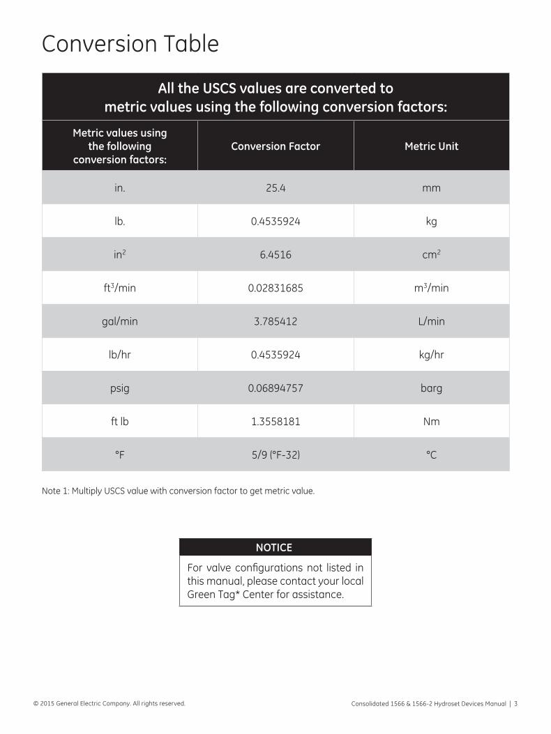
All the USCS values are converted to metric values using the following conversion factors:
Metric values using the following
conversion factors:Conversion Factor Metric Unit
in. 25.4 mm
lb. 0.4535924 kg
in2 6.4516 cm2
ft3/min 0.02831685 m3/min
gal/min 3.785412 L/min
lb/hr 0.4535924 kg/hr
psig 0.06894757 barg
ft lb 1.3558181 Nm
°F 5/9 (°F-32) °C
Conversion Table
Note 1: Multiply USCS value with conversion factor to get metric value.

4 | GE Oil & Gas © 2015 General Electric Company. All rights reserved.
Table of Contents
I. Product Safety Sign and Label System ......................................................................................................................... 5
II. Safety Alerts .............................................................................................................................................................................. 6
III. Safety Notice ............................................................................................................................................................................. 7
IV. Warranty Information .......................................................................................................................................................... 8
V. Introduction ............................................................................................................................................................................... 9
VI. Use of Applicable Valve Manuals .................................................................................................................................... 9
VII. Codes and Standards ........................................................................................................................................................ 10
VIII. Operating Principles ........................................................................................................................................................... 10
IX. Description of the Hydroset Test System ................................................................................................................. 11
X. Calibration of the Hydroset Test System .................................................................................................................. 13
XI. Pressure Test Gauges ........................................................................................................................................................ 14
A. Types of Guides to be Used ..................................................................................................................................... 14
B. Calibration of Pressure Test Gauges ................................................................................................................... 14
C. Location of Pressure Gauges .................................................................................................................................. 14
XII. Pretest Planning, Formulas and Sample Calculation .......................................................................................... 14
A. Pretest Planning ............................................................................................................................................................ 14
B. Formula ............................................................................................................................................................................. 15
C. Sample Calculation ..................................................................................................................................................... 15
XIII. Set Pressure Testing ........................................................................................................................................................... 16
A. General Information ................................................................................................................................................... 16
B. Specific Steps ................................................................................................................................................................. 16
XIV. Turnbuckle Selection Charts ........................................................................................................................................... 17
XV. Manufacturer’s Field Service and Repair Program .............................................................................................. 18
A. Field Service .................................................................................................................................................................... 18
B. Repair Facilities ............................................................................................................................................................. 18
C. Maintenance Training ................................................................................................................................................ 18
XVI. Factory Refurbishing .......................................................................................................................................................... 18
XVII. Hydroset Extended Service Plan ................................................................................................................................... 18
Consolidated 1566 & 1566-2 Hydroset Devices Manual | 5© 2015 General Electric Company. All rights reserved.
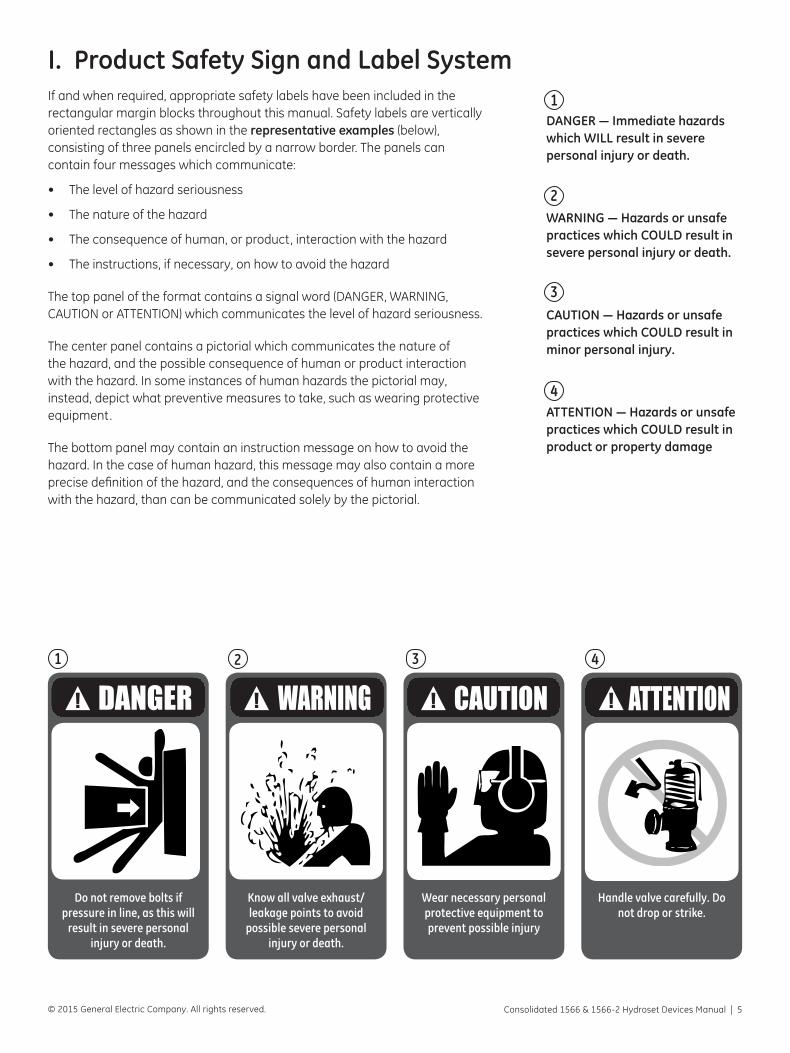
DANGER — Immediate hazards which WILL result in severe personal injury or death.
WARNING — Hazards or unsafe practices which COULD result in severe personal injury or death.
CAUTION — Hazards or unsafe practices which COULD result in minor personal injury.
ATTENTION — Hazards or unsafe practices which COULD result in product or property damage
If and when required, appropriate safety labels have been included in the rectangular margin blocks throughout this manual. Safety labels are vertically oriented rectangles as shown in the representative examples (below), consisting of three panels encircled by a narrow border. The panels can contain four messages which communicate:
• The level of hazard seriousness
• The nature of the hazard
• The consequence of human, or product, interaction with the hazard
• The instructions, if necessary, on how to avoid the hazard
The top panel of the format contains a signal word (DANGER, WARNING, CAUTION or ATTENTION) which communicates the level of hazard seriousness.
The center panel contains a pictorial which communicates the nature of the hazard, and the possible consequence of human or product interaction with the hazard. In some instances of human hazards the pictorial may, instead, depict what preventive measures to take, such as wearing protective equipment.
The bottom panel may contain an instruction message on how to avoid the hazard. In the case of human hazard, this message may also contain a more precise definition of the hazard, and the consequences of human interaction with the hazard, than can be communicated solely by the pictorial.
I. Product Safety Sign and Label System
2
3
4
1
Do not remove bolts if pressure in line, as this will
result in severe personal injury or death.
1
Know all valve exhaust/leakage points to avoid
possible severe personal injury or death.
2
Wear necessary personal protective equipment to prevent possible injury
3
Handle valve carefully. Do not drop or strike.
4
6 | GE Oil & Gas © 2015 General Electric Company. All rights reserved.
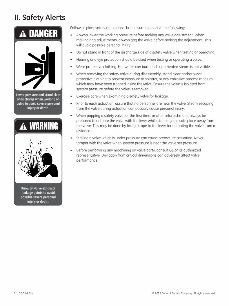
Follow all plant safety regulations, but be sure to observe the following:
• Always lower the working pressure before making any valve adjustment. When making ring adjustments, always gag the valve before making the adjustment. This will avoid possible personal injury.
• Do not stand in front of the discharge side of a safety valve when testing or operating.
• Hearing and eye protection should be used when testing or operating a valve.
• Wear protective clothing. Hot water can burn and superheated steam is not visible.
• When removing the safety valve during disassembly, stand clear and/or wear protective clothing to prevent exposure to splatter, or any corrosive process medium, which may have been trapped inside the valve. Ensure the valve is isolated from system pressure before the valve is removed.
• Exercise care when examining a safety valve for leakage.
• Prior to each actuation, assure that no personnel are near the valve. Steam escaping from the valve during actuation can possibly cause personal injury.
• When popping a safety valve for the first time, or after refurbishment, always be prepared to actuate the valve with the lever while standing in a safe place away from the valve. This may be done by fixing a rope to the lever for actuating the valve from a distance.
• Striking a valve which is under pressure can cause premature actuation. Never tamper with the valve when system pressure is near the valve set pressure.
• Before performing any machining on valve parts, consult GE or its authorized representative. Deviation from critical dimensions can adversely affect valve performance.
Lower pressure and stand clear of discharge when working on valve to avoid severe personal
injury or death.
Know all valve exhaust/leakage points to avoid
possible severe personal injury or death.
II. Safety Alerts
Consolidated 1566 & 1566-2 Hydroset Devices Manual | 7© 2015 General Electric Company. All rights reserved.
Wear necessary personal protective
equipment to prevent possible injury
Know nuclear “health physics” procedures, if applicable, to avoid
possible severe injury or death.
Proper installation and start-up is essential to the safe and reliable operation of all valve products. The relevant procedures recommended by GE, and described in these instructions, are effective methods of performing the required tasks.
It is important to note that these instructions contain various “safety messages” which should be carefully read in order to minimize the risk of personal injury, or the possibility that improper procedures will be followed which may damage the involved GE product, or render it unsafe. It is also important to understand that these “safety messages” are not exhaustive. GE can not possibly know, evaluate, and advise any customer of all of the conceivable ways in which tasks might be performed, or of the possible hazardous consequences of each way. Consequently, GE has not undertaken any such broad evaluation and, thus, anyone who uses a procedure and/or tool, which is not recommended by GE, or deviates from GE recommendations, must be thoroughly satisfied that neither personal safety, nor valve safety, will be jeopardized by the method and/or tools selected. Contact GE if there are any questions relative to tools/methods.
The installation and start-up of valves and/or valve products may involve proximity to fluids at extremely high-pressure and/or temperature. Consequently, every precaution should be taken to prevent injury to personnel during the performance of any procedure. These precautions should consist of, but are not limited to, ear drum protection, eye protection, and the use of protective clothing, (i.e., gloves, etc.) when personnel are in, or around, a valve work area. Due to the circumstances and conditions in which these operations may be performed on Consolidated products, and the possible hazardous consequences of each way, GE can not possibly evaluate all conditions that might injure personnel or equipment. Nevertheless, GE does offer certain Safety Allerts, listed in Section II, for customer information only.
It is the responsibility of the purchaser or user of GE valves/equipment to adequately train all personnel who will be working with the involved valves/equipment. For more information on training schedules, call (281) 542-3646. Further, prior to working with the involved valves/equipment, personnel who are to perform such work should become thoroughly familiar with the contents of these instructions.
III. Safety Notice
8 | GE Oil & Gas © 2015 General Electric Company. All rights reserved.
IV. Warranty InformationWarranty Statement – GE warrants that its products and work will meet all applicable specifications and other specific product and work requirements (including those of performance), if any, and will be free from defects in material and workmanship. Refer to GE’s Standard Terms of Sale, or specific contract for complete details on warranty and limitation of remedy and liability.
Defective and nonconforming items must be held for GE’s inspection and returned to the original F.O.B. point upon request.
Incorrect Selection or Misapplication of Products – GE cannot be responsible for customer’s incorrect selection or misapplication of our products.
Unauthorized Repair Work – GE has not authorized any non-affiliated repair companies, contractors or individuals to perform warranty repair service on new products or field repaired products of its manufacture. Therefore, customers contracting such repair services from unauthorized sources must do so at their own risk.
Unauthorized Removal of Seals – All new valves and valves repaired in the field by Field Service are sealed to assure the customer of our guarantee against defective workmanship. Unauthorized removal and/or breakage of this seal will negate our warranty.
Consolidated 1566 & 1566-2 Hydroset Devices Manual | 9© 2015 General Electric Company. All rights reserved.
V. IntroductionThe procedure for ensuring that a safety valve is operable, properly adjusted and provides overpressure protection, normally requires that the system be overpressurized to actuate (pop) the safety valve. Intentional overpressurization confirms valve set pressure, valve lift , valve reseat pressure, discharge stack (piping) design adequacy, and inlet piping (nozzle) design adequacy.
In many cases it is not possible, or desirable, to intentionally overpressurize a system. Therefore, some alternate technique is required and, in such cases, the 1566/1566-2 Hydroset valve tester may be used. The Hydroset is a test device that permits
verification of the set pressure of a safety valve without overpressurization. However, the Hydroset will not provide other assurances that may be obtained through a system overpressure test. The Hydroset will only open the valve slightly and, thus, valve lift is not verified. Since full lift and full flow are not obtained when testing with the Hydroset, blowdown (reseat pressure) is not accurately verified.
It is recommended that the Hydroset be used only for confirming valve set pressure, once the valve has been adjusted by the use of full system overpressure. Establishing the initial set pressure of a valve with the Hydroset is not recommended, especially if the capability exists in the system to overpressurize and adjust the safety valve. Conversely, the use of the Hydroset for “in-service” testing may be more desirable than overpressurization, since it eliminates excessive noise, reduces test and outage times, and allows for better system control.
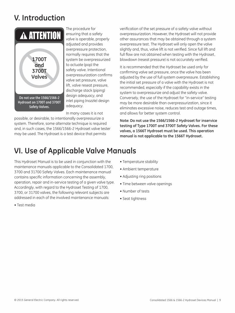
Note: Do not use the 1566/1566-2 Hydroset for inservice testing of Type 1700T and 3700T Safety Valves. For these valves, a 1566T Hydroset must be used. This operation manual is not applicable to the 1566T Hydroset.
VI. Use of Applicable Valve ManualsThis Hydroset Manual is to be used in conjunction with the maintenance manuals applicable to the Consolidated 1700, 3700 and 31700 Safety Valves. Each maintenance manual contains specific information concerning the assembly, operation, repair and in-service testing of a given valve type. Accordingly, with regard to the Hydroset Testing of 1700, 3700, or 31700 valves, the following relevant subjects are addressed in each of the involved maintenance manuals:
• Test media
• Temperature stability
• Ambient temperature
• Adjusting ring positions
• Time between valve openings
• Number of tests
• Seat tightness
1700Tand
3700TValves
Do not use the 1566/1566-2 Hydroset on 1700T and 3700T
Safety Valves.
10 | GE Oil & Gas © 2015 General Electric Company. All rights reserved.
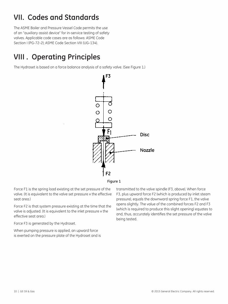
VIII . Operating PrinciplesThe Hydroset is based on a force balance analysis of a safety valve. (See Figure 1.)
Force F1 is the spring load existing at the set pressure of the valve. (It is equivalent to the valve set pressure x the effective seat area.)
Force F2 is that system pressure existing at the time that the valve is adjusted. (It is equivalent to the inlet pressure x the effective seat area.)
Force F3 is generated by the Hydroset.
When pumping pressure is applied, an upward force is exerted on the pressure plate of the Hydroset and is
transmitted to the valve spindle (F3, above). When force F3, plus upward force F2 (which is produced by inlet steam pressure), equals the downward spring force F1, the valve opens slightly. The value of the combined forces F2 and F3 (which is required to produce this slight opening) equates to and, thus, accurately identifies the set pressure of the valve being tested.
VII. Codes and StandardsThe ASME Boiler and Pressure Vessel Code permits the use of an “auxiliary assist device” for in-service testing of safety valves. Applicable code cases are as follows: ASME Code Section I (PG-72-2); ASME Code Section VIII (UG-134).
Figure 1

Consolidated 1566 & 1566-2 Hydroset Devices Manual | 11© 2015 General Electric Company. All rights reserved.
IX. Description of the Hydroset Test SystemThe Hydroset shown in Figure 2 (below) is a portable hydraulic lifting device specifically designed to determine the set pressure of Consolidated Maxiflow 1700, 3700 and 31700 safety valves. Its primary use, therefore, is not to determine the set pressure of other Consolidated safety valves or other manufacturers’ safety valves. For convenience, the Hydroset is furnished in a carrying case, together with a yoke and turnbuckle.
It should be noted that, currently, there are two Hydroset models: the 1566 and 1566-2, with the 1566-2 being the latest model. Whereas the 1566 is designed for hydraulic pressures not less than 500 psig, the 1566-2 is designed for hydraulic pressures not less than 50 psig. Maximum hydraulic pressure for both models is 2000 psig.
Figure 2
(This picture is for illustration only, Do not use for Hydroset assembly and/or repair.)
Equipment List
Part No. Nomenclature
1. Port 1/2 NPT (Plugged)
2. Brass Bushing 3/4 x 1/2 NPT
3. L.H. Threaded (Plugged)
4. Top of Pressure Plate
5. Bottom of Bevel Upper Flange
6. Port 3/8 NPT (Attach Hydraulic Hose Here)
7. Brass Bushing 1/2 x 3/8 NPT
8. Hydroset
9. Yoke
10. Hydroset Spindle
11. Turnbuckle
12. Valve Spindle
13. Equal Clearance Between Yoke and Spindle
14. Compression Screw
12 | GE Oil & Gas © 2015 General Electric Company. All rights reserved.
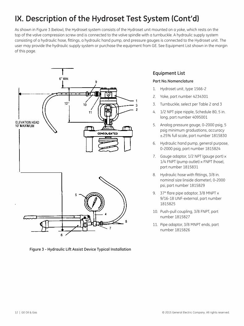
IX. Description of the Hydroset Test System (Cont’d)
Figure 3 - Hydraulic Lift Assist Device Typical Installation
As shown in Figure 3 (below), the Hydroset system consists of the Hydroset unit mounted on a yoke, which rests on the top of the valve compression screw and is connected to the valve spindle with a turnbuckle. A hydraulic supply system consisting of a hydraulic hose, fittings, a hydraulic hand pump, and pressure gauges is connected to the Hydroset unit. The user may provide the hydraulic supply system or purchase the equipment from GE. See Equipment List shown in the margin of this page.
Equipment List
Part No. Nomenclature
1. Hydroset unit, type 1566-2
2. Yoke, part number 4234301
3. Turnbuckle, select per Table 2 and 3
4. 1/2 NPT pipe nipple, Schedule 80, 5 in. long, part number 4095001
5. Analog pressure gauge, 0-2000 psig, 5 psig minimum graduations, accuracy ±.25% full scale, part number 1815830
6. Hydraulic hand pump, general purpose, 0-2000 psig, part number 1815824
7. Gauge adaptor, 1/2 NPT (gauge port) x 1/4 FNPT (pump outlet) x FNPT (hose), part number 1815831
8. Hydraulic hose with fittings, 3/8 in. nominal size (inside diameter), 0-2000 psi, part number 1815829
9. 37° flare pipe adaptor, 3/8 MNPT x 9/16-18 UNF-external, part number 1815825
10. Push-pull coupling, 3/8 FNPT, part number 1815827
11. Pipe adaptor, 3/8 MNPT ends, part number 1815826
Consolidated 1566 & 1566-2 Hydroset Devices Manual | 13© 2015 General Electric Company. All rights reserved.
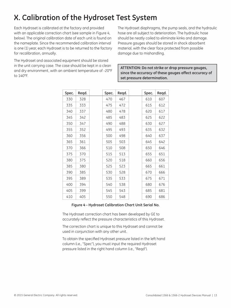
X. Calibration of the Hydroset Test SystemEach Hydroset is calibrated at the factory and provided with an applicable correction chart (see sample in Figure 4, below). The original calibration date of each unit is found on the nameplate. Since the recommended calibration interval is one (1) year, each Hydroset is to be returned to the factory for recalibration, annually.
The Hydroset and associated equipment should be stored in the unit carrying case. The case should be kept in a clean and dry environment, with an ambient temperature of -20°F to 140°F.
The Hydroset diaphragms, the pump seals, and the hydraulic hose are all subject to deterioration. The hydraulic hose should be neatly coiled to eliminate kinks and damage. Pressure gauges should be stored in shock absorbent material, with the clear face protected from possible damage due to mishandling.
ATTENTION: Do not strike or drop pressure gauges, since the accuracy of these gauges affect accuracy of set pressure determination.
Figure 4 - Hydroset Calibration Chart Unit Serial No.
Spec. Reqd. Spec. Reqd. Spec. Reqd.
330 328 470 467 610 607
335 333 475 472 615 612
340 337 480 478 620 617
345 342 485 483 625 622
350 347 490 488 630 627
355 352 495 493 635 632
360 356 500 498 640 637
365 361 505 503 645 642
370 366 510 508 650 646
375 370 515 513 655 651
380 375 520 518 660 656
385 380 525 523 665 661
390 385 530 528 670 666
395 389 535 533 675 671
400 394 540 538 680 676
405 399 545 543 685 681
410 405 550 548 690 686
The Hydroset correction chart has been developed by GE to accurately reflect the pressure characteristics of this Hydroset.
The correction chart is unique to this Hydroset and cannot be used in conjunction with any other unit.
To obtain the specified Hydroset pressure listed in the left hand column (i.e., “Spec”), you must input the required Hydroset pressure listed in the right hand column (i.e., “Reqd”).

14 | GE Oil & Gas © 2015 General Electric Company. All rights reserved.
XI. Pressure Test GaugesA. Types of Gauges to be UsedIndicating pressure gauges used in pressure testing shall be connected directly to the Hydroset. If the indicating gauge is not readily visible to the operator controlling the pressure being applied, an additional indicating gauge shall be provided where it will be visible to the operator for the duration of the test.
Either analog type or digital type pressure gauges may be used. For the Hydroset hydraulic system, analog gauges having an accuracy or ±0.25% full scale are to be used. Gauges should be selected so that test pressure is in the middle 1/3 section of the gauge. Digital gauges shall have an accuracy of ±0.1% of span. Failure to provide proper gauges may result in set pressures outside ASME Code tolerance.
B. Calibration of Pressure Test GaugesAll test gauges shall be calibrated against a standard dead weight tester or a calibrated master gauge. The test gauges shall be calibrated before each test or series of tests.
ATTENTION: Do not use uncalibrated gauges.
A series of tests is that group of tests using the same pressure test gauge or gauges, which is conducted at the same site, within a period not exceeding two weeks.
C. Location of Pressure GaugesPressure gauges measuring steam pressure upstream of the safety valve should be connected to the pipe nozzle to which the valve is mounted. If pressure measurements are taken at any other location, then the pressure differential between the gauge location and the valve location should be established. This correction should be used in the calculations of the official set pressure of the safety valve.
A pressure gauge should be located on the Hydroset pump as shown in Figure 3. An elevation head not exceeding 10 feet is recommended.
XII. Pretest Planning, Formulas and Sample CalculationA. Pretest PlanningPretest planning is essential, and consists of:
1. Definition of inlet steam test pressure,
2. Calculation of Hydroset hydraulic test pressure by using formula (below)
3. Determination of required Hydroset pressure using correction chart,
4. Testing of pressure gauges at required test pressures to determine gauge error,
5. Identification and definition of other test variables, and
6. Definition of post testing calculations.
Inlet steam test pressure must be defined and controlled within a specified tolerance. A steam test pressure of 70% to 80% of the valve set pressure is recommended. Steam test pressure must be maintained within 5 psi of the defined value. Further, hydraulic test pressure must be maintained within 5 psi of the calculated value.
Consolidated 1566 & 1566-2 Hydroset Devices Manual | 15© 2015 General Electric Company. All rights reserved.
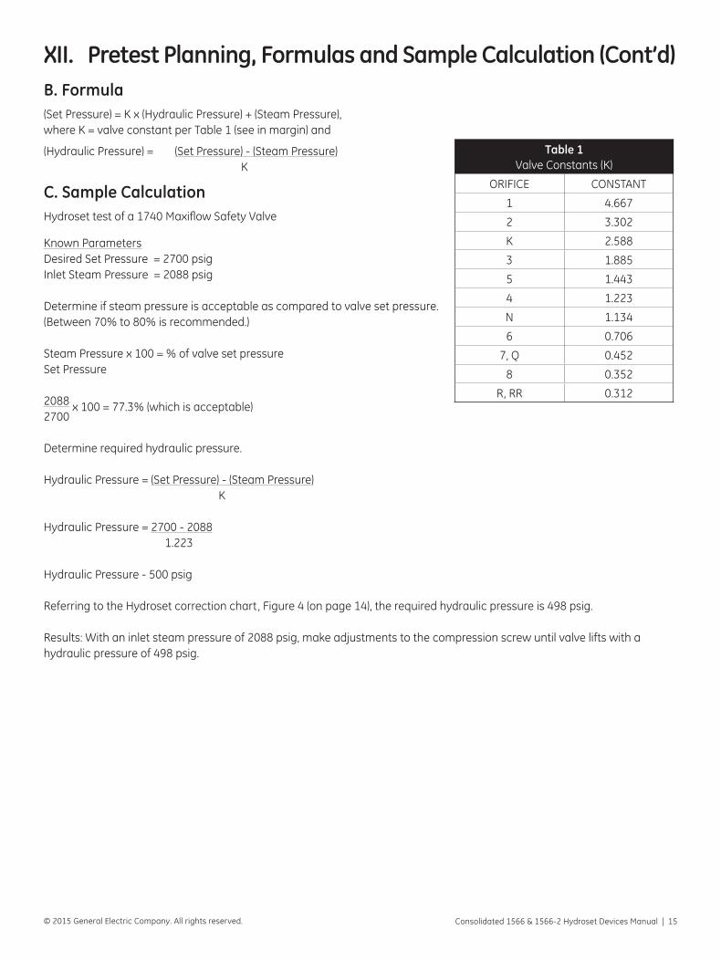
B. Formula(Set Pressure) = K x (Hydraulic Pressure) + (Steam Pressure), where K = valve constant per Table 1 (see in margin) and
(Hydraulic Pressure) = (Set Pressure) - (Steam Pressure) K
C. Sample CalculationHydroset test of a 1740 Maxiflow Safety Valve
Known ParametersDesired Set Pressure = 2700 psigInlet Steam Pressure = 2088 psig
Determine if steam pressure is acceptable as compared to valve set pressure. (Between 70% to 80% is recommended.)
Steam Pressure x 100 = % of valve set pressureSet Pressure
2088 x 100 = 77.3% (which is acceptable)2700
Determine required hydraulic pressure.
Hydraulic Pressure = (Set Pressure) - (Steam Pressure) K
Hydraulic Pressure = 2700 - 2088 1.223
Hydraulic Pressure - 500 psig
Referring to the Hydroset correction chart, Figure 4 (on page 14), the required hydraulic pressure is 498 psig.
Results: With an inlet steam pressure of 2088 psig, make adjustments to the compression screw until valve lifts with a hydraulic pressure of 498 psig.
Table 1Valve Constants (K)
ORIFICE CONSTANT
1 4.667
2 3.302
K 2.588
3 1.885
5 1.443
4 1.223
N 1.134
6 0.706
7, Q 0.452
8 0.352
R, RR 0.312
XII. Pretest Planning, Formulas and Sample Calculation (Cont’d)

16 | GE Oil & Gas © 2015 General Electric Company. All rights reserved.
XIII. Set Pressure TestingA. General InformationSet pressure testing of a safety valve can be efficiently accomplished by following the specific steps identified below.
B. Specific Steps1. Pressure the valve inlet and heat up to required
temperature profile.
ATTENTION: The Hydroset unit is not to be mounted to the valve during the heatup period.
The Hydroset unit and pump should not be used if the temperature of the unit and/or pump exceed 120°F (48.9° C). If that temperature is exceeded during usage, these components should be cooled prior to further usage.
2. To prepare the unit for use, the pump, hose, gauge and Hydroset must be assembled and filled with hydraulic oil.
Remove the Hydroset plug which is located on the side opposite the hose connection, and then lay Hydroset on its side with the open plug hole up.
Fill pump with oil and pump system full. The open hole in the Hydroset must be filled completely to the top. Stroke the Hydroset unit by grasping the spindle and pushing/pulling on the spindle. This action will remove trapped air. Upon completion of the stroking, install the plug once again.
ATTENTION: During the filling operation, the pump must be refilled to prevent air from entering system. After filling, pump reservoir must not be more than 3/4 full. All air must be removed from the pump prior to beginning a setting operation.
Before testing, be sure the Hydroset piston is located at the bottom of its travel.
3. Remove cap and release nut from top of spindle per applicable valve Installation and Maintenance Manual, if not done previously. Scrap cotter pin.
4. Clean the top of compression screw, and remove any burrs with a file.
5. Place the Hydroset yoke on top of the valve compression screw, and then place the turnbuckle on the valve spindle. See Tables 2 and 3, on page 13, for the turnbuckle applicable to the valve being tested.
6. Rotate the turnbuckle 1/2 turn on the spindle.
7. Place the Hydroset unit over the turnbuckle and engage the Hydroset spindle threads in the left hand threads of the turnbuckle.
Rotate the turnbuckle clockwise until the Hydroset unit is resting on the Hydroset yoke. The turnbuckle should be hand tightened only, and then backed off approximately one-half turn. Be sure that the valve spindle does not bind against the Hydroset yoke.
8. Prior to testing, insure that the hydraulic hose is not pinched, since this can be a possible source of error in gauge readings.
9. Pressurize the Hydroset to a value of 80% of the “expected” Hydroset test pressure value.
From the 80% value, increase the Hydroset pressure at a slow rate until the valve lifts.
Immediately upon valve lift , the Hydroset pressure should be relieved by utilizing the pump exhaust valve. If pressure is not immediately relieved, the valve may possibly chatter.
10. Record test data.
11. In order to verify test results, the procedure identified in Steps 9 and 10, above, should be repeated two (2) additional times, in order to provide three consecutive tests within ASME Code tolerances.
Consolidated 1566 & 1566-2 Hydroset Devices Manual | 17© 2015 General Electric Company. All rights reserved.
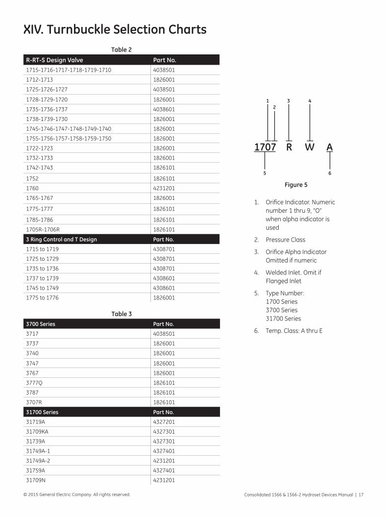
XIV. Turnbuckle Selection ChartsTable 2
R-RT-S Design Valve Part No.1715-1716-1717-1718-1719-1710 4038501
1712-1713 1826001
1725-1726-1727 4038501
1728-1729-1720 1826001
1735-1736-1737 4038601
1738-1739-1730 1826001
1745-1746-1747-1748-1749-1740 1826001
1755-1756-1757-1758-1759-1750 1826001
1722-1723 1826001
1732-1733 1826001
1742-1743 1826101
1752 1826101
1760 4231201
1765-1767 1826001
1775-1777 1826101
1785-1786 1826101
1705R-1706R 1826101
3 Ring Control and T Design Part No.
1715 to 1719 4308701
1725 to 1729 4308701
1735 to 1736 4308701
1737 to 1739 4308601
1745 to 1749 4308601
1775 to 1776 1826001
Table 33700 Series Part No.
3717 4038501
3737 1826001
3740 1826001
3747 1826001
3767 1826001
3777Q 1826101
3787 1826101
3707R 1826101
31700 Series Part No.
31719A 4327201
31709KA 4327301
31739A 4327301
31749A-1 4327401
31749A-2 4231201
31759A 4327401
31709N 4231201
1707 R W A
12
3 4
5 6
1. Orifice Indicator. Numeric number 1 thru 9, “O” when alpha indicator is used
2. Pressure Class
3. Orifice Alpha Indicator Omitted if numeric
4. Welded Inlet. Omit if Flanged Inlet
5. Type Number: 1700 Series 3700 Series 31700 Series
6. Temp. Class: A thru E
Figure 5
18 | GE Oil & Gas © 2015 General Electric Company. All rights reserved.
A. Field ServiceGE maintains the largest and most competent field service technicians in the industry. Service technicians are located at strategic points throughout the United States to respond to customer’s requirements for service, even in the event of extreme off-hour emergency situations. Each service technician is factory trained and experienced in servicing Consolidated products.
It is highly recommended that the professional expertise of a field service technician be employed to make final field adjustments during the initial setting of all Consolidated valves.
For further information, please contact your local Green Tag Center.
B. Repair FacilitiesThe GE Consolidated repair department, in conjunction with the manufacturing facilities, are equipped to perform specialized repairs and product modifications, e.g. bushing replacements, hydroset calibrations, electromatic relief valve repairs, code welding, pilot replacement, etc.
For further information, please contact your local Green Tag Center.
C. Maintenance TrainingRising costs of maintenance and repair in the utility and process industries indicate the need for trained maintenance personnel. GE conducts service seminars that can help your maintenance and engineering personnel to reduce these costs.
Seminars, conducted either at your site, or at the GE Consolidated training facility, provide participants with an introduction to the basics of preventative maintenance. These seminars help to reduce downtime, reduce unplanned repairs and increase valve safety. While they do not make “instant” experts, they do provide the participants with “Hands On” experience with Consolidated Valves. The seminar also includes valve terminology and nomenclature, component inspection, troubleshooting, setting and testing, with emphasis on the ASME Boiler and Pressure Vessel Code.
For further information, Please contact your local Green Tag Center or the GE Consolidated Training Manager at (281) 542-3646.
XV. Manufacturer’s Field Service and Repair Program
XVI. Factory RefurbishingMany customers find it desirable to return their Hydroset to GE for restoration and calibration. Consolidated products returned to the Consolidated valve renewal center are restored to original specifications and returned with a
warranty. An inventory of Consolidated service parts is available, enabling the return of refurbished Hydrosets within a short time after receipt.
XVII. Hydroset Extended Service PlanYour purchase of the Model 1566-2 Hydroset includes the following FIVE (5) Year Extended Service Plan:
1. Annual calibration for FIVE (5) years from the date of purchase.
2. One set of replacement belloframs, lower and upper, if needed, to be installed during the FIVE (5) year service period. Any other parts, or service, required will be billed at the price in effect at the time of invoicing.
3. The Hydroset unit should be returned ANNUALLY to GE’s Consolidated plant for service and calibration. All repairs and recalibration are performed by GE specialized testing equipment for optimum reliability. Shipment to and from GE is at the customer’s expense.
For more details concerning the extended service plan, please contact your local Green Tag Center.

Consolidated 1566 & 1566-2 Hydroset Devices Manual | 19© 2015 General Electric Company. All rights reserved.
GEA31927 09/2015
* Denotes a trademark of General Electric Company.
Other company names and product names used in this document are registered trademarks or trade-marks of their respective owners.
© 2015 General Electric Company. All rights reserved.
Visit us online at:
www.geoilandgas.com/valves
AUSTRALIABrisbane:Phone: +61-7-3001-4319Fax: +61-7-3001-4399
Perth:Phone: +61-8-6595-7018Fax: +61 8 6595-7299
Melbourne:Phone: +61-3-8807-6002Fax : +61-3-8807-6577
BELGIUMPhone: +32-2-344-0970Fax: +32-2-344-1123
BRAZILPhone: +55-11-2146-3600Fax: +55-11-2146-3610
CHINAPhone: +86-10-5689-3600Fax: +86-10-5689-3800
FRANCECourbevoiePhone: +33-1-4904-9000Fax: +33-1-4904-9010
GERMANYRatingenPhone: +49-2102-108-0Fax: +49-2102-108-111
INDIAMumbaiPhone: +91-22-8354790Fax: +91-22-8354791
New DelhiPhone: +91-11-2-6164175Fax: +91-11-5-1659635
ITALYPhone: +39-081-7892-111Fax: +39-081-7892-208
JAPANTokyo Phone: +81-03-6871-9008Fax: +81-03-6890-4620
KOREAPhone: +82-2-2274-0748Fax: +82-2-2274-0794
MALAYSIAPhone: +60-3-2161-0322Fax: +60-3-2163-6312
MEXICOPhone: +52-55-3640-5060
THE NETHERLANDSPhone: +31-15-3808666Fax: +31-18-1641438
RUSSIAVeliky NovgorodPhone: +7-8162-55-7898Fax: +7-8162-55-7921
MoscowPhone: +7 495-585-1276Fax: +7 495-585-1279
SAUDI ARABIAPhone: +966-3-341-0278Fax: +966-3-341-7624
SINGAPOREPhone: +65-6861-6100Fax: +65-6861-7172
SOUTH AFRICAPhone: +27-11-452-1550Fax: +27-11-452-6542
SOUTH & CENTRAL AMERICA AND THE CARIBBEANPhone: +55-12-2134-1201Fax: +55-12-2134-1238
SPAINPhone: +34-93-652-6430Fax: +34-93-652-6444
UNITED ARAB EMIRATESPhone: +971-4-8991-777Fax: +971-4-8991-778
UNITED KINGDOMBracknellPhone: +1-1344-460-500Fax: +1-1344-460-537
SkelmersdalePhone: +1-1695-526-00Fax: +1-1695-526-01
UNITED STATESMassachusettsPhone: +1-508-586-4600Fax: +1-508-427-8971
Corpus Christi, Texas Phone: +1-361-881-8182Fax: +1-361-881-8246
Deer Park, TexasPhone: +1-281-884-1000Fax: +1-281-884-1010
Houston, TexasPhone: +1-281-671-1640Fax: +1-281-671-1735
DIRECT SALES OFFICE LOCATIONS


