The foot brake operates on all four wheels.Solid or ventilated disc brakes are fitted at thefront, and self-adjusting drum or solid discbrakes are fitted at the rear, depending onmodel. Actuation is hydraulic, with vacuumservo assistance. The handbrake is cable-operated, and acts on the rear wheels only.
The hydraulic system is split into twocircuits. On non-ABS models, the system issplit diagonally, and on ABS models, thesystem is split front and rear. If there is ahydraulic fluid leak in one circuit, theremaining circuit will still function, so thatsome braking capability remains.
The hydraulic fluid supply to the rear brakesis regulated so that the front brakes always
lock first under heavy braking. The fluidpressure to the rear brakes is controlled bytwo valves, one for each brake, which areeither screwed into the master cylinder ormounted on the rear underbody of the vehicle,depending on model.
The brake servo is of the direct-acting type,fitted between the pedal and the mastercylinder. The servo is powered by vacuumdeveloped in the inlet manifold. Should theservo fail, the brakes will still operate, butincreased pedal pressure will be required.
2 Anti-lock braking system(ABS) - general
1 ABS is available as an option for all models.When the ignition is switched on, an ‘ABS’symbol illuminates in the instrument panel fora short time.
2 The system comprises an electronic controlunit, roadwheel sensors, hydraulic modulator,and the necessary valves and relays. Discbrakes are fitted to all four wheels. Thepurpose of the system is to stop wheel(s)locking during heavy brake applications. Thisis achieved by automatic release of the brakeon the locked wheel, followed by re-application of the brake. This procedure iscarried out several times a second by thehydraulic modulator. 3 The modulator is controlled by theelectronic control unit, which itself receivessignals from the wheel sensors, which monitorthe locked or unlocked state of the wheels.The two front brakes are modulatedseparately, but the two rear brakes aremodulated together.4 The ABS unit is fitted between the brakemaster cylinder and the brakes, the vacuumservo and master cylinder being of similartype for both non-ABS and ABS models.
9•2 Braking system
5 If the ‘ABS’ symbol, in the instrument panelstays lit after approximately 4 seconds, or if itcomes on sporadically or stays on whilstdriving, there is a fault in the system. Shouldthis occur, it is recommended that a completetest is carried out by a Vauxhall dealer, whowill have the necessary specialist diagnosticequipment. Due to the special equipmentrequired, it is not practical for the DIYmechanic to carry out the test procedure.6 To prevent possible damage to theelectronic control unit, always disconnect thecontrol unit wiring plug before carrying outelectrical welding work.7 It is recommended that the control unit isremoved if the vehicle is being subjected tohigh temperatures, like for instance, duringcertain paint-drying processes.8 If using steam cleaning equipment, do notaim the water/steam jet directly at the controlunit.9 Do not disconnect the control unit wiringplug with the ignition switched on.10 Do not use a battery booster to start theengine.11 After working on the ABS components,ensure that all wiring plugs are correctlyreconnected, and have the complete systemtested by a Vauxhall dealer, at the earliestopportunity.12 All models up to 1991 that were fitted withABS, used the ABS-2E system. From 1992onwards an ABS-2EH system was fitted,which can be identified by the location of theelectronic control module, which is bolted tothe hydraulic modulator.13 The main differences between the twosystems are in the electrical components andcircuits, the most obvious of these beingomission of the surge arrester relay on the2EH system.
3 Hydraulic system - bleeding 2
General1 If any of the hydraulic components in thebraking system have been removed ordisconnected, or if the fluid level in thereservoir has been allowed to fall appreciably,it is certain that air will have entered into thesystem. The removal of all this air from thehydraulic system is essential if the brakes areto function correctly, and the process ofremoving it is known as bleeding.2 Where an operation has only affected onecircuit of the hydraulic system (the system is
split diagonally on non-ABS models, and frontand rear on ABS models), then it will only benecessary to bleed the relevant circuit. If themaster cylinder has been disconnected andreconnected, or the fluid level has beenallowed to fall appreciably, then the completesystem must be bled.3 One of three methods can be used to bleedthe system, although Vauxhall recommendthe use of a pressure bleeding kit.
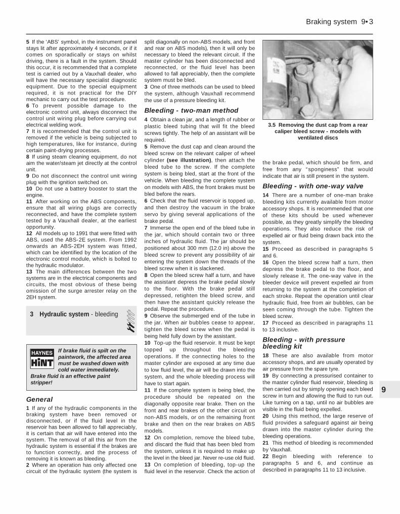
Bleeding - two-man method4 Obtain a clean jar, and a length of rubber orplastic bleed tubing that will fit the bleedscrews tightly. The help of an assistant will berequired.5 Remove the dust cap and clean around thebleed screw on the relevant caliper of wheelcylinder (see illustration), then attach thebleed tube to the screw. If the completesystem is being bled, start at the front of thevehicle. When bleeding the complete systemon models with ABS, the front brakes must bebled before the rears.6 Check that the fluid reservoir is topped up,and then destroy the vacuum in the brakeservo by giving several applications of thebrake pedal.7 Immerse the open end of the bleed tube inthe jar, which should contain two or threeinches of hydraulic fluid. The jar should bepositioned about 300 mm (12.0 in) above thebleed screw to prevent any possibility of airentering the system down the threads of thebleed screw when it is slackened.8 Open the bleed screw half a turn, and havethe assistant depress the brake pedal slowlyto the floor. With the brake pedal stilldepressed, retighten the bleed screw, andthen have the assistant quickly release thepedal. Repeat the procedure.9 Observe the submerged end of the tube inthe jar. When air bubbles cease to appear,tighten the bleed screw when the pedal isbeing held fully down by the assistant.10 Top-up the fluid reservoir. It must be kepttopped up throughout the bleedingoperations. If the connecting holes to themaster cylinder are exposed at any time dueto low fluid level, the air will be drawn into thesystem, and the whole bleeding process willhave to start again.11 If the complete system is being bled, theprocedure should be repeated on thediagonally opposite rear brake. Then on thefront and rear brakes of the other circuit onnon-ABS models, or on the remaining frontbrake and then on the rear brakes on ABSmodels.12 On completion, remove the bleed tube,and discard the fluid that has been bled fromthe system, unless it is required to make upthe level in the bleed jar. Never re-use old fluid.13 On completion of bleeding, top-up thefluid level in the reservoir. Check the action of
the brake pedal, which should be firm, andfree from any “sponginess” that wouldindicate that air is still present in the system.
Bleeding - with one-way valve14 There are a number of one-man brakebleeding kits currently available from motoraccessory shops. It is recommended that oneof these kits should be used wheneverpossible, as they greatly simplify the bleedingoperations. They also reduce the risk ofexpelled air or fluid being drawn back into thesystem.15 Proceed as described in paragraphs 5and 6.16 Open the bleed screw half a turn, thendepress the brake pedal to the floor, andslowly release it. The one-way valve in thebleeder device will prevent expelled air fromreturning to the system at the completion ofeach stroke. Repeat the operation until clearhydraulic fluid, free from air bubbles, can beseen coming through the tube. Tighten thebleed screw.17 Proceed as described in paragraphs 11to 13 inclusive.
Bleeding - with pressurebleeding kit18 These are also available from motoraccessory shops, and are usually operated byair pressure from the spare tyre.19 By connecting a pressurised container tothe master cylinder fluid reservoir, bleeding isthen carried out by simply opening each bleedscrew in turn and allowing the fluid to run out.Like turning on a tap, until no air bubbles arevisible in the fluid being expelled.20 Using this method, the large reserve offluid provides a safeguard against air beingdrawn into the master cylinder during thebleeding operations.21 This method of bleeding is recommendedby Vauxhall.22 Begin bleeding with reference toparagraphs 5 and 6, and continue asdescribed in paragraphs 11 to 13 inclusive.
Braking system 9•3
3.5 Removing the dust cap from a rearcaliper bleed screw - models with
ventilated discs
9
If brake fluid is spilt on thepaintwork, the affected areamust be washed down withcold water immediately.
Brake fluid is an effective paintstripper!
4 Front disc pads - inspection,removal and refitting 3
Note: When working on the brakecomponents, take care not to disperse brakedust into the air, or to inhale it, since it maycontain asbestos, which can damage yourhealth.
Inspection1 Where applicable, remove the wheel trims,then loosen the front roadwheel bolts andapply the handbrake. Jack up the front of thevehicle, and support on axle stands (see“Jacking and Vehicle Support”) positionedunder the body side members.2 Remove the roadwheels. Turn the steering tofull right-hand lock, and check the wear of thefriction material on the right-hand brake pads.Check that the thickness of the friction material(including the backing plate) is not less than theminimum given in the Specifications.3 Turn the steering to full left-hand lock, andcheck the left-hand brake pads in the sameway.4 If any brake pad is worn below the specifiedminimum thickness, renew all the front padsas a set.5 If the pads require renewal, continue asfollows according to model.
Removal
1.4, 1.6 and 1.8 litre models6 Note how the anti-rattle springs are located(see illustration), then drive the upper andlower pad retaining pins out from the inboardside of the caliper, using a pin punch.7 Remove the anti-rattle springs (seeillustration).8 Push the pads away from the disc slightly,then using a pair of pliers, withdraw theoutboard pad (see illustration).9 Withdraw the inboard pad, and the shimthat fits between the pad and the caliperpiston (see illustration).
Refitting10 Brush the dust and dirt from the caliper,but take care not to inhale it. Carefully removeany rust from the edge of the brake disc.
11 To accommodate the new thicker pads,the caliper piston must be depressed fully intoits cylinder bore, using a flat bar of metal suchas a tyre lever. The action of depressing thepiston will cause the fluid level in the reservoirto rise, so to avoid spillage, syphon out somefluid using an old hydrometer or a teat pipette.Refer to the note at the beginning of Section 3.Do not lever between the piston and disc todepress the piston.12 Check that the cutaway recesses in thepiston are positioned vertically. If necessary,carefully turn the piston to its correct position.13 Apply a little brake grease to the top andbottom edges of the backplates on the newbrake pads.14 Locate the new pads in the caliper,ensuring that the shim is in place between theinboard pad and the piston. Ensure that thefriction material faces the disc, and check thatthe pads are free to move slightly. 15 Locate the anti-rattle springs on the pads,then insert the pad retaining pins from theoutboard side of the caliper, while depressingthe springs. Tap the pins firmly into the caliper(see illustration).16 Repeat the operations on the remainingside of the vehicle.17 Refit the roadwheels and lower the vehicleto the ground. Do not fully tighten theroadwheel bolts until the vehicle is resting onits wheels.18 Apply the footbrake hard several times toposition the pads against the discs.19 Check and if necessary top-up the brakefluid level.
20 New brake pads should be carefullybedded in and, where possible, heavy brakingshould be avoided during the first 100 miles(160 km) or so after fitting new pads.
2.0 litre models
Removal21 Where applicable, pull the pad wearsensor from the inboard pad, and disconnectthe wiring at the connector under the wheelarch, next to the suspension strut (seeillustration). Note the wire routing.22 Using a screwdriver, prise the padretaining clip from the outboard edge of thecaliper, noting how it is located (seeillustration).23 Prise out the two guide bolt dust capsfrom the inboard edge of the caliper, thenusing a Allen key or hexagon bit, unscrew the
9•4 Braking system
4.6 Front disc pad anti-rattle springs(arrowed) - models with solid discs
4.8 Withdrawing the outboard disc pad -models with solid discs
4.21 Withdrawing the pad wear sensorfrom the inboard pad - DOHC model
4.15 Fitting a disc pad retaining pin -models with solid discs
4.9 Withdrawing the inboard disc pad andshim - models with solid discs
4.7 Removing an anti-rattle spring -models with solid discs
guide bolts, and lift the caliper and inboardpad from the bracket. Recover the outboardbrake pad (see illustrations). Suspend thecaliper body with wire or string, to avoidstraining the brake fluid hose.24 Pull the inboard pad from the caliperpiston, noting that it is retained by a clipattached to the pad backing plate (seeillustration).
Refitting25 Proceed as described in paragraphs 10to 12 inclusive (see illustration).26 Apply a little brake grease to the contactsurfaces of the new brake pads.27 Fit the new inboard pad to the caliperpiston, ensuring that the piston is correctlylocated. 28 Locate the outboard pad on the caliperbracket, with the friction material facing thedisc. 29 Refit the caliper to the bracket, andtighten the guide bolts to the specified torque(see illustration). 30 Refit the guide bolt dust caps. 31 Refit the pad retaining clip, locating it asnoted before removal. 32 Where applicable, fit a new pad wearsensor to the inboard pad, and connect thewiring at the connector under the wheel arch.Route the wiring as noted during removal. 33 Repeat the operations on the remainingside of the vehicle. 34 Proceed as described in paragraphs 17to 20 inclusive.
5 Rear disc pads - inspection,removal and refitting 3
Note: When working on the brakecomponents, take care not to disperse brakedust into the air, or to inhale it, since it maycontain asbestos, which can damage yourhealth.
Inspection1 Where applicable, remove the wheel trims,then loosen the rear roadwheel bolts andchock the front wheels. Jack up the rear of thevehicle, and support on axle stands (see“Jacking and Vehicle Support”) positionedunder the body side members. Remove theroadwheels.
2 Check the wear of the friction material onthe brake pads, on both sides of the vehicle.Check that the thickness of the frictionmaterial (including the backing plate) is notless than the minimum given in the Specifica-tions.3 If any brake pad is worn below the specifiedminimum thickness, renew all the rear pads asa set as follows.
Removal4 Note how the anti-rattle spring is located,then drive out the upper and lower padretaining pins from the outside of the caliperusing a pin punch (see illustration).5 Remove the anti-rattle spring (seeillustration).6 Push the pads away from the disc slightly,then using a pair of pliers, withdraw the
Braking system 9•5
4.23B Withdrawing the caliper, inboard andoutboard pad - models with ventilated discs
5.5 Removing a rear disc pad retaining pinanti-rattle spring
5.4 Driving out a rear disc pad retainingpin
4.29 Tightening a caliper guide bolt -models with ventilated discs
4.24 Removing the inboard pad from thecaliper piston - models with ventilated
discs
4.23A Removing a caliper guide bolt dustcap - models with ventilated discs
4.22 Prising out the disc pad retaining clip- models with ventilated discs
9
outboard pad and anti-squeal shim that fitsbetween the pad and the caliper body.7 Withdraw the inboard pad and anti-squealshim.
Refitting8 Proceed as described in Section 4,paragraphs 10 and 11.9 Check that the cutaway recesses in thepistons are positioned downwards, atapproximately 23° to the horizontal. Atemplate made of card may be used to checkthe setting (see illustration). If necessary,carefully turn the pistons to their correctpositions.10 Apply a little brake grease to the top andbottom edges of the backplates on the newbrake pads.11 Locate the new pads and the anti-squealshims in the caliper. Ensure that the frictionmaterial faces the disc, and check that thepads are free to move slightly.12 Locate the anti-rattle spring on the pads,then insert the pad retaining pins from theinside edge of the caliper, while depressingthe spring. Tap the pins firmly into the caliper.13 Repeat the operations on the remainingside of the vehicle. 14 Proceed as described in Section 4,paragraphs 17 to 20 inclusive.
3Note: When working on the brakecomponents, take care not to disperse brakedust into the air, or to inhale it, since it maycontain asbestos, which can damage yourhealth.
Inspection1 It is recommended that the brake shoes areinspected when necessary by removing thedrums. This will enable a proper inspection ofthe linings to be made, and additionally, thewheel cylinders can be inspected for leaks. Ifpreferred, however, a provisional inspection ofthe state of wear of the rear shoe linings canbe made by removing the plugs from theinspection holes in the brake backplates.
2 Use a torch or inspection lamp, and ifnecessary a mirror, to check that the frictionmaterial has not worn down to less than thespecified minimum.3 If any one of the shoes has worn below thespecified limit, all four rear brake shoes mustbe renewed as a set, as follows.
Removal4 Where applicable, remove the wheel trims,then loosen the rear roadwheel bolts andchock the front wheels. Jack up the rear of thevehicle, and support on axle stands (see“Jacking and Vehicle Support”) positionedunder the body side members. Remove theroadwheels.5 Fully release the handbrake.6 Extract the drum securing screw andremove the drum. If the drum is tight, removethe plug from the inspection hole in the brakebackplate, and push the handbrake operatinglever towards the brake shoe to move theshoes away from the drum. If necessary,slacken the handbrake cable adjuster (seeillustrations).7 Note the location and orientation of allcomponents before dismantling, as an aid toreassembly.8 Clean the dust and dirt from the drum andshoes, but take care not to inhale it.9 Remove the shoe hold-down pins, springsand cups by depressing the cups and turningthem through 90° using a pair of pliers (seeillustrations). Note that the hold-down pinsare removed through the rear of the brakebackplate.10 Disconnect the handbrake cable from theoperating lever.
11 The upper and lower return springs maynow be unhooked and the shoes removedseparately, or the assembly of shoes, adjusterstrut and springs may be removed together.Remove the hub, refer to Chapter 10, ifnecessary. Take care not to damage thewheel cylinder rubber boots. Before removingthe return springs, note the position andorientation of the springs and adjuster strut.12 If the shoes are to be removed for sometime, fit a stout rubber band or a spring clip tothe wheel cylinder, to prevent the pistons frombeing pushed out of their bores. In any event,do not press the brake pedal while the drum isremoved.
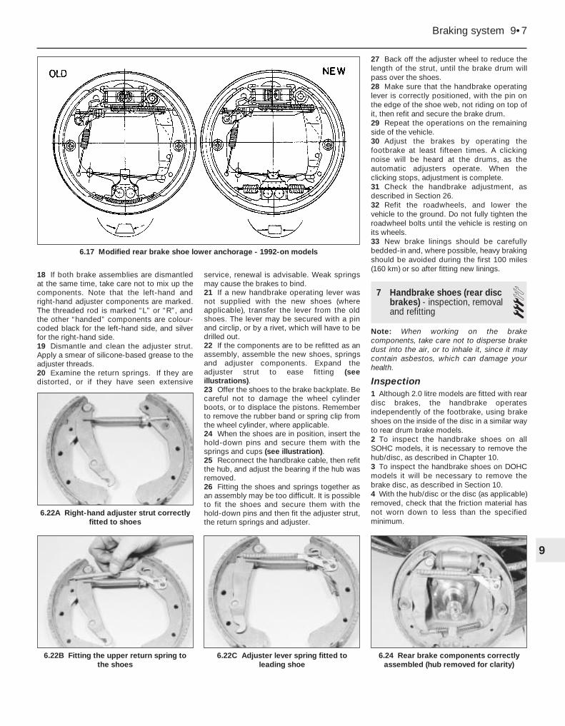
Refitting13 Clean the dust and dirt from the brakebackplate, but take care not to inhale it.14 Apply a small amount of brake grease tothe shoe rubbing areas on the backplate.15 Investigate and rectify any source ofcontamination of the linings (wheel cylinder orhub bearing oil seal leaking).16 Although linings are available separately(without shoes), renewal of the shoescomplete with linings is to be preferred,unless the reader has the necessary skills andequipment to fit new linings to the old shoes.17 If not already done, dismantle the shoes,strut and springs. Note the position andorientation of the components. On latermodels (1992-on), the brake shoe loweranchorage has been modified so that it is nowrectangular, necessitating modified brakeshoes and a modified lower return spring (seeillustration).
9•6 Braking system
5.9 Checking a rear caliper piston cutaway recess angle with a card template
6.6B Push the handbrake operating leverto move the shoes away from the drum
6.9B . . . then withdraw the cup and spring6.9A Release the shoe hold-down cup . . .
6.6A Extracting a brake drum securingscrew
18 If both brake assemblies are dismantledat the same time, take care not to mix up thecomponents. Note that the left-hand andright-hand adjuster components are marked.The threaded rod is marked “L” or “R”, andthe other “handed” components are colour-coded black for the left-hand side, and silverfor the right-hand side.19 Dismantle and clean the adjuster strut.Apply a smear of silicone-based grease to theadjuster threads.20 Examine the return springs. If they aredistorted, or if they have seen extensive
service, renewal is advisable. Weak springsmay cause the brakes to bind.21 If a new handbrake operating lever wasnot supplied with the new shoes (whereapplicable), transfer the lever from the oldshoes. The lever may be secured with a pinand circlip, or by a rivet, which will have to bedrilled out.22 If the components are to be refitted as anassembly, assemble the new shoes, springsand adjuster components. Expand theadjuster strut to ease fitting (seeillustrations).23 Offer the shoes to the brake backplate. Becareful not to damage the wheel cylinderboots, or to displace the pistons. Rememberto remove the rubber band or spring clip fromthe wheel cylinder, where applicable.24 When the shoes are in position, insert thehold-down pins and secure them with thesprings and cups (see illustration).25 Reconnect the handbrake cable, then refitthe hub, and adjust the bearing if the hub wasremoved.26 Fitting the shoes and springs together asan assembly may be too difficult. It is possibleto fit the shoes and secure them with thehold-down pins and then fit the adjuster strut,the return springs and adjuster.
27 Back off the adjuster wheel to reduce thelength of the strut, until the brake drum willpass over the shoes.28 Make sure that the handbrake operatinglever is correctly positioned, with the pin onthe edge of the shoe web, not riding on top ofit, then refit and secure the brake drum.29 Repeat the operations on the remainingside of the vehicle.30 Adjust the brakes by operating thefootbrake at least fifteen times. A clickingnoise will be heard at the drums, as theautomatic adjusters operate. When theclicking stops, adjustment is complete.31 Check the handbrake adjustment, asdescribed in Section 26.32 Refit the roadwheels, and lower thevehicle to the ground. Do not fully tighten theroadwheel bolts until the vehicle is resting onits wheels.33 New brake linings should be carefullybedded-in and, where possible, heavy brakingshould be avoided during the first 100 miles(160 km) or so after fitting new linings.
3Note: When working on the brakecomponents, take care not to disperse brakedust into the air, or to inhale it, since it maycontain asbestos, which can damage yourhealth.
Inspection1 Although 2.0 litre models are fitted with reardisc brakes, the handbrake operatesindependently of the footbrake, using brakeshoes on the inside of the disc in a similar wayto rear drum brake models. 2 To inspect the handbrake shoes on allSOHC models, it is necessary to remove thehub/disc, as described in Chapter 10. 3 To inspect the handbrake shoes on DOHCmodels it will be necessary to remove thebrake disc, as described in Section 10.4 With the hub/disc or the disc (as applicable)removed, check that the friction material hasnot worn down to less than the specifiedminimum.
Braking system 9•7
6.22A Right-hand adjuster strut correctlyfitted to shoes
6.24 Rear brake components correctlyassembled (hub removed for clarity)
5 If any one of the shoes has worn below thespecified limit, all four handbrake shoes mustbe renewed as a set, as follows.
SOHC models
Removal6 Clean the dust and dirt from the variouscomponents, but take care not to inhale it.7 Disconnect the handbrake cable and thereturn spring from the handbrake operatinglever at the brake backplate. If necessary,slacken the handbrake cable adjustment, withreference to Section 26.8 Remove the shoe hold-down pins, springsand cups by depressing the cups and turningthem through 90° using a pair of pliers. Notethat the hold-down pins are removed throughthe rear of the brake backplate.9 The shoes, adjuster, handbrake operatinglever and return springs can now be removedtogether as an assembly.10 Note the position and orientation of allcomponents, then unhook the upper andlower return springs from the shoes, andrecover the handbrake operating lever and theadjuster.
Refitting11 Apply a little brake grease to the threadsof the adjuster, then screw it together to itsminimum length. Also apply a little brakegrease to the shoe rubbing areas on thelockplate.12 Fit one of the new brake shoes, andsecure it to the backplate with the hold-downpin, spring and cup.13 Fit the handbrake operating lever inposition.14 Fit the remaining brake shoe, and securewith the hold-down pin, spring and cup.15 Hook the upper return spring onto theshoes.16 Fit the adjuster between the lower ends ofthe shoes, as noted before dismantling, thenfit the lower return spring (see illustrations).17 Reconnect the handbrake cable and thereturn spring to the handbrake operatinglever.18 Refit the hub/disc, and adjust the wheelbearing play, as described in Chapter 10, butdo not refit the roadwheel at this stage.19 Repeat the operations on the remainingside of the vehicle.
20 Check the handbrake cable adjustment,as described in Section 26. 21 Refit the roadwheels and lower the vehicleto the ground. Do not fully tighten theroadwheel bolts until the vehicle is resting onits wheels.
DOHC models
Removal22 Proceed as described in paragraphs 6and 7.23 Remove the shoe hold-down pins, springsand cups by turning the cups through using ascrewdriver. Note that the hold-down pins areremoved through the rear of the brakebackplate. Note also the position andorientation of all components, then unhookthe upper and lower return springs from theshoes, and recover the handbrake operatinglever and the adjuster.
Refitting24 Proceed as described in paragraphs 11 to14 inclusive. 25 Hook the lower return spring onto theshoes.26 Fit the adjuster between the upper ends ofthe shoes, as noted before dismantling, thenfit the upper return spring (see illustration).27 Reconnect the handbrake cable and thereturn spring to the handbrake operatinglever.28 Refit the brake disc as described inSection 10, but do not refit the roadwheel atthis stage.29 Proceed as described in paragraphs 19to 21 inclusive.
8 Front disc caliper - removal,overhaul and refitting 3
Note: Refer to the note at the beginning ofSection 3 before proceeding. Beforedismantling a caliper, check that replacementparts can be obtained, and retain the oldcomponents to compare them with the newones. New sealing rings must be used on thefluid hose union bolt on refitting
Models with solid discs
Removal1 Where applicable, remove the wheel trims,then loosen the relevant front roadwheel boltsand apply the handbrake. Jack up the front ofthe vehicle, and support securely on axlestands (see “Jacking and Vehicle Support”)positioned under the body side members.Remove the roadwheel.2 Remove the brake disc pads, as describedin Section 4.3 Working under the bonnet, remove thebrake fluid reservoir cap, and secure a pieceof polythene over the filler neck with a rubberband, or by refitting the cap. This will reducethe loss of fluid during the followingprocedure.4 Unscrew the brake fluid hose union boltfrom the rear of the caliper, and disconnectthe hose. Recover the two sealing rings fromthe union bolt (one either side of the hose endfitting). Be prepared for fluid spillage, and plugthe open ends to prevent dirt ingress andfurther fluid loss.5 Prise out the two caliper bracket mountingbolt dust caps from the inboard edge of thecaliper bracket, then using an Allen key orhexagon bit, unscrew the mounting bolts, andwithdraw the caliper assembly from thevehicle.
Overhaul6 If desired, the caliper can be overhauled asfollows. Otherwise, go on to paragraph 24 fordetails of refitting.7 Brush the dirt and dust from the caliper, buttake care not to inhale it. 8 Mount the caliper bracket in a soft-jawedvice. Then separate the caliper body from themounting bracket by pressing the front face ofthe caliper body downwards and simultane-ously sliding the caliper body from thelocating pins on the bracket. Recover theguide springs from the bracket, noting theirorientation.9 Using a screwdriver, prise the dust sealretaining clip from the piston dust seal, thencarefully prise off the dust seal.10 Place a thin piece of wood in front of thepiston to prevent it from falling out of its boreand sustaining damage. Then apply low airpressure - e.g. from a foot pump - to thehydraulic fluid union hole in the rear of thecaliper body, to eject the piston from its bore.
9•8 Braking system
7.16A Fitting the lower shoe return spring- SOHC models
7.26 Handbrake shoe adjuster and upperreturn spring correctly fitted - DOHC models
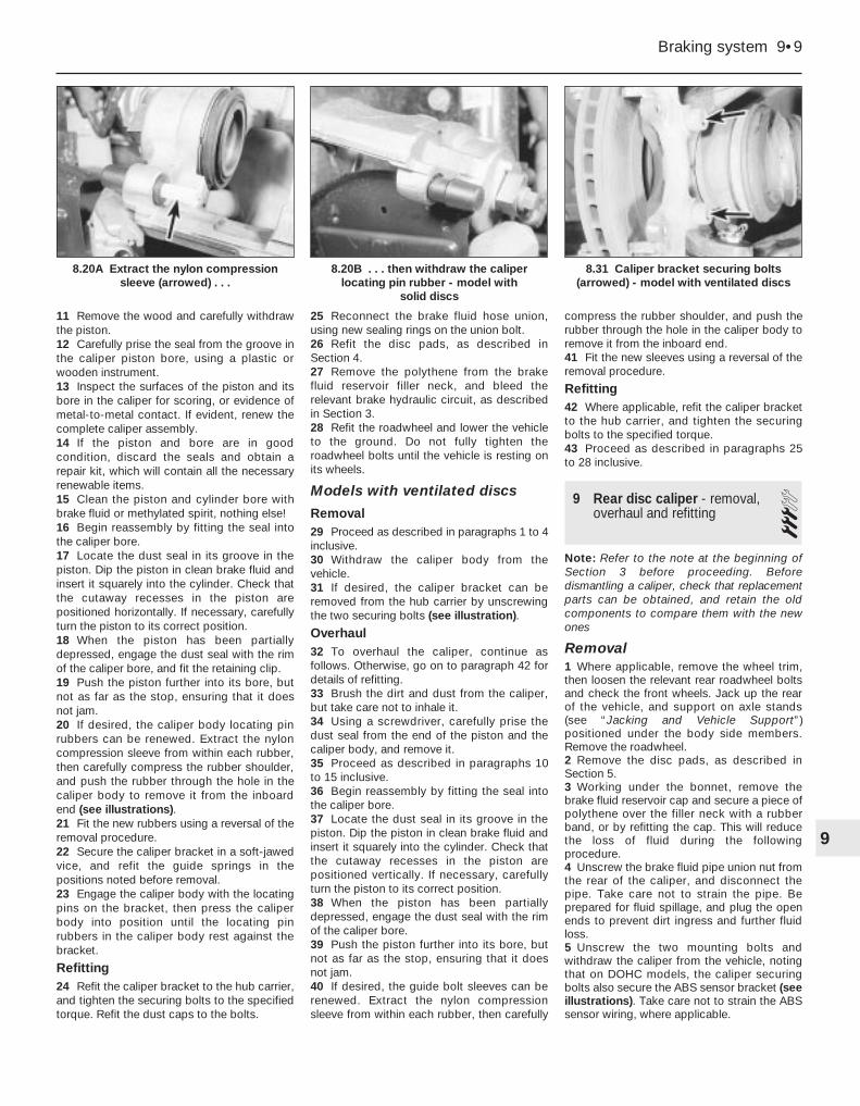
11 Remove the wood and carefully withdrawthe piston.12 Carefully prise the seal from the groove inthe caliper piston bore, using a plastic orwooden instrument.13 Inspect the surfaces of the piston and itsbore in the caliper for scoring, or evidence ofmetal-to-metal contact. If evident, renew thecomplete caliper assembly.14 If the piston and bore are in goodcondition, discard the seals and obtain arepair kit, which will contain all the necessaryrenewable items. 15 Clean the piston and cylinder bore withbrake fluid or methylated spirit, nothing else!16 Begin reassembly by fitting the seal intothe caliper bore.17 Locate the dust seal in its groove in thepiston. Dip the piston in clean brake fluid andinsert it squarely into the cylinder. Check thatthe cutaway recesses in the piston arepositioned horizontally. If necessary, carefullyturn the piston to its correct position.18 When the piston has been partiallydepressed, engage the dust seal with the rimof the caliper bore, and fit the retaining clip.19 Push the piston further into its bore, butnot as far as the stop, ensuring that it doesnot jam.20 If desired, the caliper body locating pinrubbers can be renewed. Extract the nyloncompression sleeve from within each rubber,then carefully compress the rubber shoulder,and push the rubber through the hole in thecaliper body to remove it from the inboardend (see illustrations). 21 Fit the new rubbers using a reversal of theremoval procedure.22 Secure the caliper bracket in a soft-jawedvice, and refit the guide springs in thepositions noted before removal.23 Engage the caliper body with the locatingpins on the bracket, then press the caliperbody into position until the locating pinrubbers in the caliper body rest against thebracket.
Refitting24 Refit the caliper bracket to the hub carrier,and tighten the securing bolts to the specifiedtorque. Refit the dust caps to the bolts.
25 Reconnect the brake fluid hose union,using new sealing rings on the union bolt.26 Refit the disc pads, as described inSection 4.27 Remove the polythene from the brakefluid reservoir filler neck, and bleed therelevant brake hydraulic circuit, as describedin Section 3.28 Refit the roadwheel and lower the vehicleto the ground. Do not fully tighten theroadwheel bolts until the vehicle is resting onits wheels.
Models with ventilated discs
Removal29 Proceed as described in paragraphs 1 to 4inclusive. 30 Withdraw the caliper body from thevehicle.31 If desired, the caliper bracket can beremoved from the hub carrier by unscrewingthe two securing bolts (see illustration).
Overhaul32 To overhaul the caliper, continue asfollows. Otherwise, go on to paragraph 42 fordetails of refitting.33 Brush the dirt and dust from the caliper,but take care not to inhale it.34 Using a screwdriver, carefully prise thedust seal from the end of the piston and thecaliper body, and remove it.35 Proceed as described in paragraphs 10to 15 inclusive.36 Begin reassembly by fitting the seal intothe caliper bore.37 Locate the dust seal in its groove in thepiston. Dip the piston in clean brake fluid andinsert it squarely into the cylinder. Check thatthe cutaway recesses in the piston arepositioned vertically. If necessary, carefullyturn the piston to its correct position.38 When the piston has been partiallydepressed, engage the dust seal with the rimof the caliper bore.39 Push the piston further into its bore, butnot as far as the stop, ensuring that it doesnot jam.40 If desired, the guide bolt sleeves can berenewed. Extract the nylon compressionsleeve from within each rubber, then carefully
compress the rubber shoulder, and push therubber through the hole in the caliper body toremove it from the inboard end.41 Fit the new sleeves using a reversal of theremoval procedure.
Refitting42 Where applicable, refit the caliper bracketto the hub carrier, and tighten the securingbolts to the specified torque.43 Proceed as described in paragraphs 25to 28 inclusive.
9 Rear disc caliper - removal,overhaul and refitting 3
Note: Refer to the note at the beginning ofSection 3 before proceeding. Beforedismantling a caliper, check that replacementparts can be obtained, and retain the oldcomponents to compare them with the newones
Removal1 Where applicable, remove the wheel trim,then loosen the relevant rear roadwheel boltsand check the front wheels. Jack up the rearof the vehicle, and support on axle stands(see “Jacking and Vehicle Support”)positioned under the body side members.Remove the roadwheel.2 Remove the disc pads, as described inSection 5.3 Working under the bonnet, remove thebrake fluid reservoir cap and secure a piece ofpolythene over the filler neck with a rubberband, or by refitting the cap. This will reducethe loss of fluid during the followingprocedure.4 Unscrew the brake fluid pipe union nut fromthe rear of the caliper, and disconnect thepipe. Take care not to strain the pipe. Beprepared for fluid spillage, and plug the openends to prevent dirt ingress and further fluidloss.5 Unscrew the two mounting bolts andwithdraw the caliper from the vehicle, notingthat on DOHC models, the caliper securingbolts also secure the ABS sensor bracket (seeillustrations). Take care not to strain the ABSsensor wiring, where applicable.
Braking system 9•9
8.31 Caliper bracket securing bolts(arrowed) - model with ventilated discs
8.20B . . . then withdraw the caliperlocating pin rubber - model with
solid discs
8.20A Extract the nylon compressionsleeve (arrowed) . . .
9
Overhaul6 If desired, the caliper can be overhauled asfollows. Otherwise, go on to paragraph 20 fordetails of refitting.7 Brush the dirt and dust from the caliper, buttake care not to inhale it. 8 Note that no attempt must be made toseparate the two halves of the caliper.9 Using a screwdriver, prise the dust sealretaining clips from the piston dust seals, thencarefully prise off the dust seals.10 Using a clamp, secure one of the pistonsin its fully retracted position. Then apply lowair pressure (e.g. from a foot pump), to thehydraulic fluid union hole in the rear of thecaliper body, to eject the remaining pistonfrom its bore. Take care not to drop thepiston, which may result in damage.11 Temporarily close off the bore of theremoved piston, using a flat piece of wood orsimilar improvised tool. Then remove theclamp from the remaining piston, and againapply air pressure to the caliper union to ejectthe piston.12 Carefully prise the seals from the groovesin the caliper piston bores, using a plastic orwooden instrument.13 Inspect the surfaces of the pistons andtheir bores in the caliper for scoring, orevidence of metal-to-metal contact. If evident,renew the complete caliper assembly.14 If the pistons and bores are in goodcondition, discard the seals and obtain arepair kit, which will contain all the necessaryrenewable items. Also obtain a tube of brakecylinder paste.15 Clean the piston and cylinder bore withbrake fluid or methylated spirit - nothing else!16 Apply a little brake cylinder paste to thepistons, cylinder bores and piston seals.17 Begin reassembly by fitting the seals tothe grooves in the caliper bores.18 Locate the dust seals in their grooves inthe pistons, then insert the pistons carefullyinto their bores until they enter the seals. Itmay be necessary to rotate the pistons toprevent them from jamming in the seals.19 When the pistons have been partiallydepressed, engage the dust seals with therims of the caliper bores, and fit the retainingclips.
Refitting20 Refit the caliper and tighten the securingbolts to the specified torque, ensuring that theABS sensor bracket is in position, whereapplicable.21 Reconnect the brake fluid pipe to thecaliper, and tighten the union nut.22 Refit the disc pads, as described inSection 5.23 Remove the polythene from the brakefluid reservoir filler neck and bleed therelevant brake hydraulic circuit, as describedin Section 3. 24 Refit the roadwheel and lower the vehicleto the ground. Do not fully tighten theroadwheel bolts until the vehicle is resting onits wheels.
10 Brake disc - inspection,removal and refitting 3
Inspection1 Where applicable, remove the wheel trim,then loosen the relevant roadwheel bolts. Ifchecking a front disc, apply the handbrake,and if checking a rear disc, chock the frontwheels, then jack up the relevant end of thevehicle and support on axle stands (see“Jacking and Vehicle Support”) positionedunder the body side members. Remove theroadwheel.2 Where applicable, check that the brake discsecuring screw is tight. Then fit a spacerapproximately 10.0 mm (0.4 in) thick to one ofthe roadwheel bolts, and refit and tighten thebolt in the hole opposite the disc securingscrew (see illustration).3 Rotate the brake disc, and examine it fordeep scoring or grooving. Light scoring isnormal, but if excessive, the disc should beremoved and either renewed or machined(within the specified limits) by an engineeringworks.4 Using a dial gauge, or a flat metal block andfeeler blades, check that the disc run-out doesnot exceed the figure given in the Specifications.Measure the run-out 10.0 mm (0.4 in) in from theouter edge of the disc.
5 On all SOHC models, if the rear disc run-out is excessive, check the rear wheel bearingadjustment, as described in Chapter 10.6 If the front disc run-out (all models), or therear disc run-out (DOHC models), isexcessive, remove the disc as described laterin this Section. Check that the disc-to-hubsurfaces are perfectly clean. Refit the disc andcheck the run-out again.7 If the run-out is still excessive, the discshould be renewed.8 To remove a disc, continue as follows.
Front disc
Removal9 Where applicable, remove the roadwheelbolt and spacer used when checking the disc.10 Remove the disc pads, (Section 4).11 On 2.0 litre models, unscrew the twosecuring bolts and remove the caliperbracket.12 Remove the securing screw and withdrawthe disc from the hub, where applicable tiltingit to clear the brake caliper (see illustration).
Refitting13 Refitting is a reversal of removal, butmake sure that the mating faces of the discand hub are perfectly clean, and apply a littlelocking fluid to the threads of the securingscrew. Refit the disc pads, (Section 4).
Rear disc - SOHC models14 On these models, the disc is integral withthe rear hub, and removal and refitting isdescribed in Chapter 10.
9•10 Braking system
9.5A Withdrawing a rear caliper mountingbolt . . .
10.2 Refit a wheel bolt and spacer(arrowed) opposite the disc securing screw
(A) before checking brake disc run-out
10.12 Removing a disc securing screw -SOHC model
9.5B . . . which also secures the ABSsensor bracket - DOHC model
Rear disc - DOHC models
Removal15 Where applicable, remove the roadwheelbolt and spacer used when checking the disc.16 Remove the disc pads, as described inSection 5.17 Remove the brake caliper with referenceto Section 9, but leave the hydraulic fluid pipeconnected. Move the caliper to one side, andsuspend it using wire or string to avoidstraining the pipe.18 Remove the securing screw and withdrawthe disc from the hub (see illustration). If thedisc is tight, collapse the handbrake shoes byinserting a screwdriver through the adjusterhole in the disc and turning the adjusterwheel.
Refitting19 Refitting is a reversal of removal, butmake sure that the mating faces of the discand hub are perfectly clean, and apply a littlelocking fluid to the threads of the securingscrew. Refit the disc pads, as described inSection 5.
11 Brake drum - removal,inspection and refitting 3
Note: When working on the brakecomponents, take care not to disperse brakedust into the air, or to inhale it, since it maycontain asbestos, which can damage yourhealth.
Removal1 Where applicable, remove the wheel trim,then loosen the relevant rear roadwheel boltsand chock the front wheels. Jack up the rearof the vehicle, and support on axle stands(see “Jacking and Vehicle Support”)positioned under the body side members.Remove the roadwheel.2 Fully release the handbrake.3 Extract the drum securing screw andremove the drum. If the drum is tight, removethe plug from the inspection hole in the brakebackplate, and push the handbrake operatinglever towards the brake shoe to move the
shoes away from the drums. If necessary,slacken the handbrake cable adjuster.
Inspection4 Brush the dirt and dust from the drum,taking care not to inhale it.5 Examine the internal friction surface of thedrum. If they are deeply scored, or so wornthat the drum has become ridged to the widthof the shoes, then both drums must berenewed.6 Regrinding of the friction surface is notrecommended, since the internal diameter ofthe drum will no longer be compatible with theshoe friction material contact diameter.
Refitting7 Refit the brake drum and tighten thesecuring screw. If necessary, back off theadjuster wheel until the drum will pass overthe shoes.8 Adjust the brakes by operating thefootbrake a number of times. A clicking noisewill be heard at the drum as the automaticadjuster operates. When the clicking stops,adjustment is complete.9 Refit the roadwheel and lower the vehicle tothe ground. Do not fully tighten the roadwheelbolts until the vehicle is resting on its wheels.
3Note: Refer to the notes at the beginning ofSections 3 and 11 before proceeding. Beforedismantling a wheel cylinder, check thatreplacement parts can be obtained, and retainthe old components to compare them with thenew ones
Removal1 Where applicable, remove the wheel trim,then loosen the relevant rear roadwheel boltsand chock the front wheels. Jack up the rearof the vehicle and support on axle stands (see“Jacking and Vehicle Support”) positionedunder the body side members. Remove theroadwheel.2 Fully release the handbrake.
3 Extract the drum securing screw andremove the drum. If the drum is tight, removethe plug from the inspection hole in the brakebackplate, and push the handbrake operatinglever towards the brake shoe to move theshoes away from the drum. If necessary,slacken the handbrake cable adjuster.4 Using a pair of pliers, unhook the upperreturn spring from the brake shoes, noting itsorientation, then push the upper ends of theshoes apart until they are clear of the wheelcylinder (see illustration).5 Working under the bonnet, remove thebrake fluid reservoir cap and secure a piece ofpolythene over the filler neck with a rubberband, or by refitting the cap. This will reducethe loss of fluid during the followingprocedure.6 Unscrew the brake fluid pipe union nut fromthe rear of the wheel cylinder, and disconnectthe pipe (see illustration). Take care not tostrain the pipe. Be prepared for fluid spillage,and plug the open ends to prevent dirt ingressand further fluid loss.7 Unscrew the two securing bolts from therear of the brake backplate, and withdraw thewheel cylinder.
Overhaul8 If desired, the wheel cylinder can beoverhauled as follows. Otherwise, go on toparagraph 17 for details of refitting.9 Brush the dirt and dust from the wheelcylinder, but take care not to inhale it.10 Pull the rubber dust seals from the ends ofthe cylinder body.11 The pistons will normally be ejected bythe pressure of the coil spring. If they are not,tap the end of the cylinder body on a piece ofwood, or apply low air pressure (e.g. from afoot pump), to the hydraulic fluid union hole inthe rear of the cylinder body, to eject thepistons from their bores.12 Inspect the surfaces of the pistons andtheir bores in the cylinder body for scoring, orevidence of metal-to-metal contact. If evident,renew the complete wheel cylinder assembly.Note that the later type of wheel cylinder canbe used to replace the early type as acomplete unit.
Braking system 9•11
12.6 Unscrewing rear wheel cylinder brakefluid pipe union
13 If the pistons and bores are in goodcondition, discard the seals and obtain arepair kit, which will contain all the necessaryrenewable items. Later models (1992-on), arefitted with L-shaped piston seals (seeillustrations). Ensure that the correct repairkit is obtained when overhauling a wheelcylinder, as the early and later componentsare not interchangeable.14 Lubricate the piston seals with cleanbrake fluid, and insert them into the cylinderbores with the spring between them, usingfinger pressure only.15 Dip the pistons in clean brake fluid, andinsert them into the cylinder bores.16 Fit the dust seals, and check that thepistons can move freely in their bores.
Refitting17 Refit the wheel cylinder to the backplate,and tighten the securing bolts.18 Reconnect the brake fluid pipe to thecylinder, and tighten the union nut.19 Push the brake shoes against the pistons,then refit the upper return spring as notedbefore removal.20 Refit the brake drum and tighten thesecuring screw. If necessary, back off theadjuster wheel until the drum will pass overthe shoes.21 Remove the polythene from the brakefluid reservoir filler neck, and bleed therelevant brake hydraulic circuit, as describedin Section 3. 22 Adjust the brakes by operating thefootbrake a number of times. A clicking noisewill be heard at the drum as the automaticadjuster operates. When the clicking stops,adjustment is complete.23 Refit the roadwheel and lower the vehicleto the ground. Do not fully tighten theroadwheel bolts until the vehicle is resting onits wheels.
13 Rear brake backplate -removal and refitting 3
Models with rear drum brakes
Removal1 Where applicable, remove the wheel trim,then loosen the relevant rear roadwheel boltsand chock the front wheels. Jack up the rearof the vehicle, and support on axle stands(see “Jacking and Vehicle Support”)positioned under the body side members.Remove the roadwheel.2 Remove the brake drum with reference toSection 11.3 Remove the rear hub, (Chapter 10). 4 Remove the brake shoes, (Section 6).5 Remove the brake wheel cylinder, asdescribed in Section 12.6 Using a screwdriver, prise out the lockplatethat secures the handbrake cable in thebackplate.7 Unscrew the four securing bolts, andwithdraw the stub axle and backplate.
Refitting8 Refitting is a reversal of removal,remembering the following points.9 Coat the rear face of the stub axle flangewith a little lithium-based grease.10 Tighten the brake backplate/stub axlesecuring bolts to the specified torque, in thethree stages given in the Specifications.11 Refit the brake wheel cylinder, asdescribed in Section 12. 12 Refit the brake shoes, as described inSection 6.13 Refit the rear hub, as described inChapter 10. 14 Refit the brake drum with reference toSection 11.15 Before refitting the roadwheel andlowering the vehicle to the ground, check andif necessary adjust the handbrake, asdescribed in Section 26.
Models with rear disc brakes(SOHC models)
Removal16 Proceed as described in paragraphs 1to 7.17 Remove the rear hub/disc, (Chapter 10). 18 Remove the handbrake shoes, (Section 7).19 Unscrew the four securing bolts, andwithdraw the stub axle and lockplate.
Refitting20 Refitting is a reversal of removal,remembering the following points.21 Coat the rear face of the stub axle flangewith a little lithium-based grease.22 Tighten the brake backplate/stub axlesecuring bolts to the specified torque, in thethree stages given in the Specifications.23 Refit the handbrake shoes, as describedin Section 7.24 Refit the rear hub/disc, (Chapter 10).25 Before refitting the roadwheel andlowering the vehicle to the ground, check andif necessary adjust the handbrake, asdescribed in Section 26.
DOHC models
Removal26 Proceed as described in paragraphs 1to 7.27 Remove the brake disc (Section 10).28 Remove the rear hub, (Chapter 10). 29 Remove the handbrake shoes, (Section 7).30 Using a splined key, unscrew the foursecuring bolts and withdraw the backplate.
Refitting31 Refitting is a reversal of removal,remembering the following points.32 Refit the handbrake shoes, (Section 7).33 Refit the rear hub, (Chapter 10). 34 Refit the brake disc (Section 10).35 Before refitting the roadwheel andlowering the vehicle to the ground, check andif necessary adjust the handbrake, asdescribed in Section 26.
9•12 Braking system
12.13A Exploded view of a rear brakewheel cylinder
14 Front brake disc shield -removal and refitting 3
Removal1 Where applicable, remove the wheel trim,then loosen the relevant front roadwheel boltsand apply the handbrake. Jack up the front ofthe vehicle, and support on axle stands (see“Jacking and Vehicle Support”) positionedunder the body side members. Remove theroadwheel.2 Remove the brake disc, as described inSection 10.3 Using a screwdriver inserted through theholes in the hub flange, extract the threescrews securing the disc shield to the hubcarrier.4 Using plate shears or an alternative tool, cuta section of metal from the rear edge of theshield to enable the shield to be withdrawnover the hub, then remove the shield (seeillustration).
Refitting5 If a new shield is to be fitted, cut out asection of metal, as during removal of the oldshield, to enable the shield to be fitted.Smooth the cut edges, and coat them withanti-corrosion paint.6 Further refitting is a reversal of removal,remembering the following points.7 Refit the brake disc, as described inSection 10.8 Do not fully tighten the roadwheel bolts untilthe vehicle is resting on its wheels.
15 Master cylinder - removal andrefitting 4
Note: Refer to the note at the beginning ofSection 3 before proceeding
Removal1 Disconnect the battery negative lead.2 Depress the footbrake pedal several timesto dissipate the vacuum in the servo unit.
3 Disconnect the wiring plug from the brakefluid level sensor in the reservoir filler cap.4 If possible, use a teat pipette or an oldhydrometer to remove the brake fluid from thereservoir. This will reduce the loss of fluid laterin the procedure.5 Locate a container beneath the mastercylinder, to catch the brake fluid that will bereleased.6 Identify the brake fluid pipes for position,then unscrew the union nuts and disconnectthe pipes from the master cylinder.7 Unscrew the two securing nuts, andwithdraw the master cylinder from the studson the vacuum servo unit (see illustration).8 Clean the external surfaces of the cylinder,then using a screwdriver carefully prise thefluid reservoir and its seals from the top of thecylinder.9 If desired, on models without ABS, themaster cylinder can be overhauled, asdescribed in Section 16.10 No overhaul of the master cylinder ispossible on models with ABS, see Section 17.
Refitting11 Refitting is a reversal of removal, but usenew seals when fitting the brake fluidreservoir, and on completion, bleed thecomplete brake hydraulic system, asdescribed in Section 3.
16 Master cylinder (non-ABS) -overhaul 4
Note: Before dismantling the master cylinder,check that replacement parts can be obtainedand retain the old components to comparethem with the new ones1 With the master cylinder removed asdescribed in Section 15, continue as follows,according to type.
GMF type master cylinder2 Clamp the master cylinder in a soft-jawedvice.3 Where applicable, unscrew the pressure-proportioning valves from the base of thecylinder.
4 Carefully prise out the sealing ring from theend of the cylinder bore. 5 Depress the primary piston slightly using apiece of wood or plastic. Then hold the pistonin the depressed position by inserting asmooth pin or rod of 3.0 mm (0.12 in) diameterthrough the primary fluid reservoir port in thecylinder (see illustration).6 Extract the circlip from the end of thecylinder bore using a screwdriver. Take carenot to damage the piston or cylinder bore.7 Withdraw the pin or rod retaining the piston.8 Withdraw the primary piston assembly fromthe cylinder, if necessary tapping the cylinderon a wooden block to free the piston from thebore.9 Apply low air pressure - e.g. from a footpump - to the front fluid reservoir port in thecylinder, to eject the secondary pistonassembly.10 Clean all the components, in clean brakefluid or methylated spirit only, and examinethem for wear and damage. In particular,check the surfaces of the pistons and cylinderbore for scoring and corrosion. If the boreshows signs of wear, renew the completemaster cylinder assembly (see illustration).11 If the cylinder bore is in good condition,obtain a repair kit, which will contain all thenecessary renewable items. A Vauxhall dealerwill supply a pre-assembled kit of parts, whichshould be fitted as follows.12 Lubricate the cylinder bore with cleanbrake fluid or brake grease, then clamp thecylinder in a soft-jawed vice, with the borehorizontal.13 Remove the plug from the end of theassembly tube, and insert the short part of thetube into the cylinder bore as far as theshoulder on the tube.14 Use a piece of wood or plastic to push thecomponents out of the tube and into thecylinder bore. Then hold the primary piston inthe depressed position by inserting the pin orrod used during dismantling through thecylinder primary fluid reservoir port.15 Fit a new circlip to the end of the cylinderbore, ensuring that it seats correctly, and thatthe piston is free to move.16 Depress the primary piston, and withdrawthe pin or rod from the fluid reservoir port.
Braking system 9•13
16.5 Holding the primary piston depressedwhile extracting the circlip from the
cylinder body - GMF type master cylinder
15.7 Master cylinder securing nut(arrowed)
14.4 Cutting a section of metal from a newfront brake disc shield prior to fitting
9
17 Fit a new sealing ring to the end of thecylinder bore.18 Where applicable, screw the pressure-proportioning valves into the base of thecylinder.19 Refit the master cylinder, as described inSection 15.
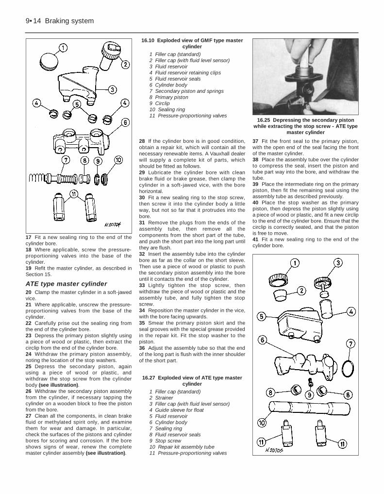
ATE type master cylinder20 Clamp the master cylinder in a soft-jawedvice.21 Where applicable, unscrew the pressure-proportioning valves from the base of thecylinder.22 Carefully prise out the sealing ring fromthe end of the cylinder bore.23 Depress the primary piston slightly usinga piece of wood or plastic, then extract thecirclip from the end of the cylinder bore.24 Withdraw the primary piston assembly,noting the location of the stop washers.25 Depress the secondary piston, againusing a piece of wood or plastic, andwithdraw the stop screw from the cylinderbody (see illustration). 26 Withdraw the secondary piston assemblyfrom the cylinder, if necessary tapping thecylinder on a wooden block to free the pistonfrom the bore.27 Clean all the components, in clean brakefluid or methylated spirit only, and examinethem for wear and damage. In particular,check the surfaces of the pistons and cylinderbores for scoring and corrosion. If the boreshows signs of wear, renew the completemaster cylinder assembly (see illustration).
28 If the cylinder bore is in good condition,obtain a repair kit, which will contain all thenecessary renewable items. A Vauxhall dealerwill supply a complete kit of parts, whichshould be fitted as follows.29 Lubricate the cylinder bore with cleanbrake fluid or brake grease, then clamp thecylinder in a soft-jawed vice, with the borehorizontal.30 Fit a new sealing ring to the stop screw,then screw it into the cylinder body a littleway, but not so far that it protrudes into thebore.31 Remove the plugs from the ends of theassembly tube, then remove all thecomponents from the short part of the tube,and push the short part into the long part untilthey are flush.32 Insert the assembly tube into the cylinderbore as far as the collar on the short sleeve.Then use a piece of wood or plastic to pushthe secondary piston assembly into the boreuntil it contacts the end of the cylinder.33 Lightly tighten the stop screw, thenwithdraw the piece of wood or plastic and theassembly tube, and fully tighten the stopscrew.34 Reposition the master cylinder in the vice,with the bore facing upwards.35 Smear the primary piston skirt and theseal grooves with the special grease providedin the repair kit. Fit the stop washer to thepiston.36 Adjust the assembly tube so that the endof the long part is flush with the inner shoulderof the short part.
37 Fit the front seal to the primary piston,with the open end of the seal facing the frontof the master cylinder.38 Place the assembly tube over the cylinderto compress the seal, insert the piston andtube part way into the bore, and withdraw thetube.39 Place the intermediate ring on the primarypiston, then fit the remaining seal using theassembly tube as described previously.40 Place the stop washer as the primarypiston, then depress the piston slightly usinga piece of wood or plastic, and fit a new circlipto the end of the cylinder bore. Ensure that thecirclip is correctly seated, and that the pistonis free to move.41 Fit a new sealing ring to the end of thecylinder bore.
9•14 Braking system
16.25 Depressing the secondary pistonwhile extracting the stop screw - ATE type
42 Where applicable, screw the pressure-proportioning valves into the base of thecylinder.43 Refit the master cylinder, as described inSection 15.
17 Master cylinder (ABS) -general
The master cylinder fitted to models withABS cannot be dismantled, and no attemptshould be made at overhaul.
If faulty, the complete unit must berenewed, as described in Section 15.
18 Vacuum servo - descriptionand testing
Description1 The vacuum servo is fitted between thebrake pedal and the master cylinder, andprovides assistance to the driver when thepedal is depressed, reducing the effort requiredto operate the brakes. The unit is operated byvacuum from the inlet manifold. With the brakepedal released, vacuum is channelled to bothsides of the internal diaphragm. However,when the pedal is depressed, one side of thediaphragm is opened to atmosphere, resultingin assistance to the pedal effort. Should thevacuum servo develop a fault, the hydraulicsystem is not affected, but greater effort will berequired at the pedal.
Testing2 The operation of the servo can be checkedas follows.3 With the engine stopped, destroy thevacuum in the servo by depressing the brakepedal several times.4 Hold the brake pedal depressed and startthe engine. The pedal should sink slightly asthe engine is started.5 If the pedal does not sink, check the servovacuum hose for leaks.6 If no defects are found in the vacuum hose,the fault must lie in the servo itself.
7 No overhaul of the servo is possible, and iffaulty, the complete unit must be renewed.
19 Vacuum servo - removal andrefitting 4
Note: During the 1989 model year, somevehicles were produced with the brake pedalheight incorrectly set, resulting in the brakepedal resting approximately 15.0 mm (0.6 in)above the clutch pedal instead of 4.0 mm(0.16 in below). The correct pedal height canbe set by adjusting the vacuum servooperating fork dimension, as described inparagraphs 15 and 16
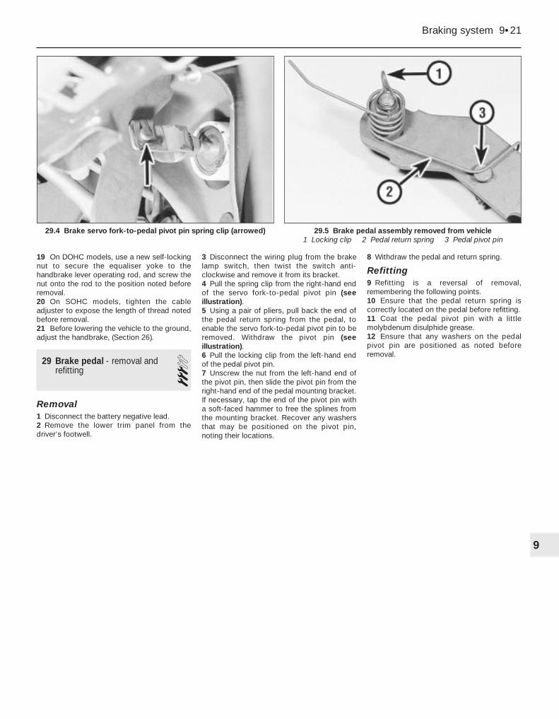
Removal1 Disconnect the battery negative lead.2 Working inside the vehicle, remove thelower trim panel from the driver’s footwell.3 Disconnect the wiring plug from the brakelamp switch, then twist the switch anti-clockwise and remove it from its bracket.4 Pull the spring clip from the right-hand endof the servo fork-to-pedal pivot pin.5 Using a pair of pliers, pull back the end ofthe pedal return spring from the pedal, toenable the servo fork-to-pedal pivot pin to beremoved. Withdraw the pivot pin.6 Remove the windscreen cowl panel, asdescribed in Chapter 11, then remove thewindscreen wiper motor and linkage asdescribed in Chapter 12.
7 Remove the coolant expansion tank asdescribed in Chapter 3.8 Pull the vacuum pipe from the brake servo.9 Unscrew the two securing nuts, andcarefully withdraw the brake master cylinderfrom the studs on the servo. Move the mastercylinder forwards slightly, taking care not tostrain the brake pipes.10 Remove the two plugs covering the servosecuring bolts from the cowl panel (seeillustrations).11 Using a Allen key or hexagon bit, unscrewthe servo securing bolts and remove themcompletely, then lift the servo from thebulkhead (see illustrations).12 If desired, the mounting bracket can beremoved from the servo by unscrewing thefour securing nuts. Note that the bracket willstick to the servo, as it is fitted with sealingcompound.13 The servo cannot be overhauled, and iffaulty, the complete unit must be renewed.
Refitting14 Before refitting the servo, check that theoperating fork dimension is correct as follows.15 Measure the distance from the end face ofthe servo casing to the centre of the pivot pinhole in the end of the operating fork. Thedistance should be 144.0 mm (5.6 in). Tomake accurate measurement easier, insert abolt or bar of similar diameter through thepivot pin hole, and measure to the centre ofthe bolt or bar (see illustration).
Braking system 9•15
19.11A Unscrew the securing bolts . . . 19.15 Measuring the servo operating forkdimension using a bolt inserted through
the pivot pin hole
19.11B . . . and withdraw the servo
19.10B . . . to expose the servo securingbolts
19.10A Remove the plugs . . .
9
16 If adjustment is necessary, slacken thelocknut, turn the fork to give the specifieddimension, then tighten the locknut.17 Where applicable, coat the contact facesof the servo and the mounting bracket withsealing compound, then refit the bracket tothe servo, and tighten the securing nuts to thespecified torque.18 Coat the threads of the servo securingbolts with locking fluid, then fit the servo tothe bulkhead and tighten the securing bolts.19 Refit the securing bolt cover plugs to thecowl panel.20 Refit the master cylinder to the servo, andtighten the securing nuts to the specifiedtorque.21 Reconnect the vacuum pipe to the servo.22 Refit the coolant expansion tank, asdescribed in Chapter 3.23 Refit the windscreen wiper motor andlinkage as described in Chapter 12, then refitthe windscreen cowl panel.24 Further refitting is a reversal of removal.On completion, test the operation of theservo, as described in Section 18.
20 ABS hydraulic modulator -removal and refitting 4
Note: Refer to Section 2, and the note at thebeginning of Section 3, before proceeding
Removal1 Disconnect the battery negative lead.2 Remove the brake fluid reservoir cap, andsecure a piece of polythene over the fillerneck with a rubber band, or by refitting thecap. This will reduce the loss of fluid duringthe following procedure.3 Remove the securing screw, and withdrawthe plastic cover from the hydraulicmodulator.4 Remove the two clamp screws, and lift offthe modulator wiring harness clamp (seeillustration).5 Disconnect the modulator wiring plug,levering it from the socket with a screwdriver ifnecessary.
6 Unscrew the brake fluid pipe union nuts,and disconnect the pipes from the modulator.Be prepared for fluid spillage, and plug theopen ends to prevent dirt ingress and furtherfluid loss. Move the pipes just clear of themodulator, taking care not to strain them.7 Unscrew the three modulator securing nuts(see illustration), then tilt the modulatorslightly, and withdraw it upwards from itsbracket, sufficiently to gain access to theearth lead securing nut at the front lower edgeof the modulator.8 Unscrew the securing nut and disconnectthe earth lead, then withdraw the modulatorfrom the vehicle, taking care not to spill brakefluid on the vehicle paintwork.9 If a new modulator is to be fitted, pull thetwo relays from the top of the old modulator,and transfer them to the new unit. No attemptmust be made to dismantle the modulator.
Refitting10 Before refitting the modulator, check thatthe bolts securing the mounting bracket to thebody panel are tight, and that the modulatorrubber mountings are in good condition.Renew the rubber mountings if necessary.11 Refitting is a reversal of removal,remembering the following points.12 Make sure that the earth lead isreconnected before fitting the modulator to itsmounting bracket.
13 On completion, remove the polythenesheet from the brake fluid reservoir filler neck,and bleed the complete brake hydraulicsystem, as described in Section 3.14 Check that the ABS warning lampextinguishes when first starting the engineafter the modulator has been removed. At theearliest opportunity, take the vehicle to aVauxhall dealer, and have the completesystem tested, using the dedicated ABS testequipment.
21 ABS wheel sensors - removaland refitting 3
Note: Refer to Section 2 before proceeding
Front wheel sensor
Removal1 Disconnect the battery negative lead.2 Where applicable, remove the wheel trim,then loosen the relevant front roadwheel boltsand apply the handbrake. Jack up the front ofthe vehicle, and support on axle stands (see“Jacking and Vehicle Support”) positionedunder the body side members. Remove theroadwheel.3 Unclip the sensor wiring connector from theretaining clip under the wheel arch, thenseparate the two halves of the wiringconnector, prising them apart with ascrewdriver if necessary (see illustration).4 Using a Allen key or hexagon bit, unscrewthe bolt securing the wheel sensor to itsmounting bracket, then carefully lever thesensor from the bracket using a screwdriver(see illustration). Recover the seal ring.
Refitting5 Examine the condition of the seal ring, andrenew if necessary.6 Refitting is a reversal of removal,remembering the following points.7 Smear a little grease on the sensor casingbefore fitting it to the bracket.8 Do not fully tighten the roadwheel bolts untilthe vehicle is resting on its wheels.9 Check that the ABS warning lampextinguishes when first starting the engineafter a wheel sensor has been removed. At
9•16 Braking system
20.4 ABS hydraulic modulator (coverremoved)
1 Wiring harnessclamp screws
2 Earth lead3 Relays
21.3 Front wheel sensor wiring underwheelarch - DOHC model
1 ABS sensor connector2 Disc pad wear sensor wiring connector
21.4 ABS front wheel sensor securing bolt(arrowed) - DOHC model
the earliest opportunity, take the vehicle to aVauxhall dealer, and have the completesystem tested, using the dedicated ABS testequipment.
Rear wheel sensor
Removal10 Disconnect the battery negative lead.11 Where applicable, remove the wheel trim,then loosen the relevant rear roadwheel boltsand chock the front wheels. Jack up the rearof the vehicle, and support on axle stands(see “Jacking and Vehicle Support”)positioned under the body side members.Remove the roadwheel.12 Unclip the sensor wiring connector fromthe retaining clip on the rear underbody, thenseparate the two halves of the wiringconnector, prising them apart with ascrewdriver if necessary (see illustration).13 Note the routing of the sensor wiring, and,where applicable, release it from the clips onthe underbody.14 Using a Allen key or hexagon bit, unscrewthe bolt securing the wheel sensor to thetrailing arm (or the mounting bracket onDOHC models), then carefully lever the sensorfrom its location using a screwdriver (seeillustration). Recover the seal ring.
Refitting15 Proceed as described in paragraphs 5 to 9inclusive.
22 ABS electronic controlmodule - removal and refitting 3
Note: Refer to Section 2 before proceeding
ABS-2E systems
Removal1 Ensure that the ignition is switched off, thendisconnect the battery negative lead.2 The control module is located under acover in the passenger sill, to the left-handside of the seat.3 Extract the three securing screws, and liftthe cover from the control module. Note thattwo of the screws are covered by plastic trimplugs.
4 Lift the control module from its recess, thenrelease the retaining clip and disconnect themodule wiring plug. Withdraw the module(see illustrations).
Refitting5 Refitting is a reversal of removal.6 Check that the ABS warning lampextinguishes when first starting the engineafter the module has been removed. At theearliest opportunity, take the vehicle to aVauxhall dealer, and have the completesystem tested, using the dedicated ABS testequipment.
ABS-2EH systems
Removal7 Ensure that the ignition is switched off, thendisconnect the battery negative lead.8 Remove the cover from the hydraulicmodulator.9 Disconnect both the wiring harness andsolenoid valve connectors.10 Relays can only be removed from controlunits that have slanted covers (seeillustration). The relays for the solenoid valveand pump motor, if removable, can now beremoved. If the unit has a flat cover, and isfaulty, the whole unit will have to be replaced.11 Undo fixing bolts and remove the controlunit.
Refitting12 Refitting is a reversal of removal. Referalso to paragraph 6.
23 ABS relays (ABS-2E systemsonly) - removal and refitting 2
Note: Refer to Section 2 before proceeding.For ABS-2EH system relays, refer toparagraphs 7 to 12, in Section 22.
Solenoid valve and pump motorrelays
Removal1 The solenoid valve and pump motor relaysare mounted on the hydraulic modulator.2 Disconnect the battery negative lead.3 Remove the securing screw and withdrawthe plastic cover from the hydraulicmodulator.4 Pull out the appropriate relay. The smallrelay is for the solenoid valve, and the largerelay is for the pump motor.
Refitting5 Refitting is a reversal of removal.6 Check that the ABS warning lampextinguishes when first starting the engineafter a relay has been removed. At the earliestopportunity, take the vehicle to a Vauxhalldealer, and have the complete system tested,using the dedicated ABS test equipment.
Surge arrester relay
Removal7 The surge arrester relay is located in therelay box at the left rear of the enginecompartment.
Braking system 9•17
22.4A Lift out the ABS control module . . . 22.10 ABS-2EH control unit1 Slanted cover type 2 Flat cover type
22.4B . . . and release the wiring plugretaining clip - ABS-2E system
8 Disconnect the battery negative lead.9 Unclip the lid and open the relay box, thenpull out the relay (see illustration).
Refitting10 Refitting is a reversal of removal, withreference to paragraph 6.
24 Rear brake pressure-proportioning valves -removal and refitting
4Note: Refer to the note at the beginning ofSection 3 before proceeding. Note also thatthe valve must only be renewed in pairs, andboth valves must be of the same calibration.Ensure that correct type of valves are fitted.The bodies have been stamped for easieridentification.
Master cylinder-mounted valves
Removal1 Remove the brake fluid reservoir cap, andsecure a piece of polythene over the fillerneck with a rubber band, or by refitting thecap. This will reduce the loss of fluid duringthe following procedure.2 Locate a container beneath the mastercylinder, to catch the brake fluid that will bereleased.3 Identify the two lower brake pipes forposition, then unscrew the union nuts anddisconnect the pipes from the proportioningvalves in the base of the master cylinder. Plugthe open ends of the pipes to prevent dirtingress.4 Unscrew the proportioning valves from themaster cylinder, and plug the open ends ofthe cylinder to prevent dirt ingress.
Refitting5 Refitting is a reversal of removal, but oncompletion, remove the polythene from thebrake fluid reservoir filler neck, and bleed thecomplete hydraulic system, as described inSection 3.
Rear underbody-mounted valves
Removal6 Proceed as described in paragraph 1.7 Chock the front wheels, then jack up therear of the vehicle, and support securely onaxle stands (see “Jacking and VehicleSupport”) positioned under the body sidemembers.8 Working under the rear of the vehicle,unscrew the union nut and disconnect thebrake pipe from one of the valves. Beprepared for fluid spillage, and plug the openend of the pipe to prevent dirt ingress andfurther fluid spillage.9 Similarly, disconnect the flexible hose fromthe valve.10 Pull the valve retaining clip from thebracket on the underbody, noting that oncertain models, the retaining clip also securesthe ABS sensor wiring, and withdraw the valve(see illustration).11 Repeat the procedure for the other valve.
Refitting12 Proceed as described in paragraph 5.
25 Brake fluid pipes and hoses- general, removal and refitting 4
Note: Refer to the note at the beginning ofSection 3, before proceeding.
General1 When checking the condition of thesystem’s pipes and/or hoses, carefully checkthat they do not foul other components suchas the power steering gear pipes (whereapplicable), so that there is no risk of thepipes chafing. If necessary use clips or ties tosecure braking system pipes and hoses wellclear of other components.
Rigid pipes
Removal2 Some of the commonly used brake pipescan be obtained from Vauxhall parts dealers,ready-formed and complete with unions, butother brake pipes must be prepared using4.75 mm (0.19 in) diameter brake pipe. Kits formaking the brake pipes can be obtained fromcertain motor accessory shops.3 Before removing a brake pipe, remove thebrake fluid reservoir cap, and secure a pieceof polythene over the filler neck with a rubberband, or by refitting the cap. This will reducethe loss of fluid when the pipe isdisconnected.
4 Jack up the vehicle, and support securelyon axle stands (see “Jacking and VehicleSupport”) positioned under the body sidemembers.5 To remove a brake pipe, unscrew theunions at each end, and release the pipe fromthe retaining clips.
Refitting6 Refitting is a reversal of removal, takingcare not to overtighten the unions.7 On completion, remove the polythene fromthe brake fluid reservoir filler neck, and bleedthe relevant hydraulic circuit(s), as describedin Section 3.
Flexible hoses
Removal8 Proceed as described previously for therigid pipes, but note that a flexible pipe mustnever be installed twisted, although a slight“set” is permissible to give it clearance fromadjacent components.
Refitting9 When reconnecting a flexible hose to afront brake caliper, note that the sealing ringson the union bolt must be renewed.
26 Handbrake - adjustment 2Models with rear drum brakes1 The handbrake will normally be kept incorrect adjustment by the self-adjustingaction of the rear brake shoes. However, dueto cable stretch over a period of time, thetravel of the handbrake lever may becomeexcessive, in which case the followingoperations should be carried out.2 Chock the front wheels, jack up the rear ofthe vehicle, and support securely on axlestands (see “Jacking and Vehicle Support”)positioned under the body side members.3 Fully release the handbrake.4 Turn the knurled nut on the cable adjuster(mounted on the torsion beam), until the brakeshoes can just be heard to rub when the rearwheels are turned by hand in the normaldirection of rotation (see illustration).
9•18 Braking system
23.9 ABS surge arrester relay (arrowed)
26.4 Handbrake cable adjuster. Knurlednut arrowed - all SOHC models
24.10 Brake pressure-proportioning valveon rear underbody - DOHC model
1 Valve 2 Retaining clip
5 Loosen the adjuster nut until the wheels arejust free to turn.6 The handbrake must start to operate withthe lever on the second notch of the ratchet.7 On completion of adjustment, check thehandbrake cables for free movement, andapply a little grease to the adjuster threads toprevent corrosion.8 Lower the vehicle to the ground.
Models with rear disc brakes9 Where applicable, remove the wheel trims,then loosen the rear roadwheel bolts andchock the front wheels. Jack up the rear of thevehicle, and support securely on axle stands(see “Jacking and Vehicle Support”)positioned under the body side members.Remove the roadwheels.10 Pull the handbrake lever as far as thesecond notch on the ratchet. 11 On DOHC models fitted with a catalyticconverter, unscrew the four securing nuts andwithdraw the exhaust centre box heat shieldby carefully sliding it round the centre box.12 On all SOHC models, loosen the knurlednut on the cable adjuster (mounted on thetorsion beam).13 On DOHC models, loosen the nutsecuring the cable equaliser yoke to thehandbrake lever operating rod.14 Using a screwdriver inserted through theadjuster hole in one of the discs/hubs (seeillustration), turn the adjuster wheel until thebrake shoes can just be heard to rub when thedisc/hub is turned by hand in the normaldirection of rotation.15 Turn the adjuster wheel back until thedisc/hub is just free to turn. 16 Repeat paragraphs 14 and 15 on theremaining side of the vehicle. 17 Tighten the nut on the cable adjuster orthe equaliser, as applicable, until the brake
shoes just begin to operate. Check that theshoes operate equally on both wheels.18 Fully release the handbrake, then apply itagain.19 The discs/hubs must lock when thehandbrake lever reaches the sixth notch onthe ratchet. If necessary, turn the nut on thecable adjuster or equaliser, as applicable, toachieve this.20 Where applicable, refit the exhaust heatshield.21 Refit the roadwheels and lower the vehicleto the ground. Do not fully tighten theroadwheel bolts until the vehicle is resting onits wheels.
27 Handbrake cable - removaland refitting 3
Models with rear drum brakes
Removal1 The handbrake cable is in two sections. Thelonger section runs from the handbrakeoperating rod, through the adjuster, to theright-hand brake assembly. The shortersection runs from the adjuster to the left-handbrake assembly. The two sections of the cablecan be renewed independently.2 Where applicable, remove the wheel trim(s),then loosen the relevant rear roadwheel bolts.Chock the front wheels, jack up the rear of thevehicle, and support securely on axle stands(see “Jacking and Vehicle Support”)positioned under the body side members.Remove the roadwheel(s).3 Note the routing of the handbrake cable(s),as an aid to refitting.4 Remove the relevant brake drum(s), withreference to Section 11.
Longer cable
Removal5 Note the length of exposed thread at thehandbrake cable adjuster on the torsionbeam, then unscrew the adjuster nut from thethreaded rod.6 Disconnect the cable from the handbrakelever operating rod on the vehicle underbody(see illustration).7 Detach the cable from the guides on theunderbody. Note that the cable can be fedthrough certain guides, but in some cases, theguide brackets must be bent away from theunderbody to allow the cable to be withdrawn.8 Detach the cable from the adjuster on thetorsion beam.9 Unhook the cable end from the lever on thebrake shoe, then using a screwdriver, priseout the lockplate that secures the handbrakecable in the backplate.10 Withdraw the cable from the vehicle,releasing it from the guide on the torsionbeam.
Refitting11 Refitting is a reversal of removal,remembering the following points.12 Screw the adjuster nut onto the threadedrod to the position noted before removal. 13 Ensure that the handbrake cable is routedas noted before removal. 14 Refit the brake drum, (Section 11). 15 Before refitting the roadwheel(s) andlowering the vehicle to the ground, adjust thehandbrake, as described in Section 26.
Shorter cable
Removal16 Note the length of exposed thread at thehandbrake cable adjuster on the torsionbeam, then unscrew the adjuster nut from thethreaded rod. Continue as described inparagraphs 8 to 10.
Braking system 9•19
27.6 Handbrake cable connection to handbrake lever operatingrod
1 Handbrake cable2 Connecting link
3 Handbrake lever operating rod
26.14 Using a screwdriver to turn the handbrake adjuster wheel -model with rear disc brakes
9
Refitting17 Proceed as described in paragraphs 11to 15 inclusive.
Models with rear disc brakes(SOHC)
General18 The procedure is as described for modelswith rear drum brakes, remembering thefollowing points.19 Ignore the references to removal andrefitting of the brake drum.20 Note that there is no lockplate securingthe handbrake cable to the brake backplate,but the return spring must be unhooked fromthe cable end.21 On models with a catalytic converter,when removing the longer cable, unscrew thefour securing nuts and withdraw the exhaustcentre box heat shield by carefully sliding itround the centre box.
DOHC models
Removal22 The left and right-hand handbrake cables,and the equaliser yoke, are removed as anassembly on DOHC models.23 Loosen the rear roadwheel bolts, thenchock the front wheels, jack up the rear of thevehicle, and support securely on axle stands(see “Jacking and Vehicle Support”)positioned under the body side members.Remove the roadwheels.24 Note the routing of the handbrake cables,as an aid to refitting.25 On models with a catalytic converter,unscrew the four securing nuts and withdrawthe exhaust centre box heat shield bycarefully sliding it round the centre box.26 Note the length of exposed thread at thecable equaliser yoke, then unscrew thesecuring nut and disconnect the equaliseryoke from the handbrake lever operating rod.27 Unhook the cable ends from the brakeshoe operating levers and the return springs(see illustration).28 Detach the cable from the guides on theunderbody and the semi-trailing arms. Notethat the cables can be fed through certain
guides, but in some cases, the guide bracketsmay have to be bent away from theunderbody to allow the cables to bewithdrawn.29 Withdraw the cables and equaliserassembly from the vehicle.
Refitting30 Refitting is a reversal of removal,remembering the following points.31 Use a new self-locking nut to secure theequaliser yoke to the handbrake leveroperating rod, and screw the nut onto the rodto the position noted before removal.32 Ensure that the cables are routed asnoted before removal.33 Before refitting the roadwheels andlowering the vehicle to the ground, adjust thehandbrake, as described in Section 26.
28 Handbrake lever - removaland refitting 3
Removal1 Disconnect the battery negative lead.2 Jack up the vehicle, and support on axlestands (see “Jacking and Vehicle Support”)positioned securely under the body sidemembers.3 On models with a catalytic converter,unscrew the four securing nuts and withdrawthe exhaust centre box heat shield bycarefully sliding it round the centre box.4 On all SOHC models, note the length ofexposed thread at the handbrake cable adjusteron the torsion beam, then slacken the adjusterto enable the cable to be disconnected from thehandbrake lever operating rod. Disconnect thecable from the operating rod and slide therubber sealing grommet from the underbodyand operating rod.5 On DOHC models, note the length ofexposed thread at the handbrake cableequaliser yoke, then unscrew the securing nutand disconnect the equaliser yoke from thehandbrake lever operating rod. Slide therubber sealing grommet from the underbodyand operating rod.6 Remove the front passenger seat, asdescribed in Chapter 11.
7 Remove the rear section of the centreconsole, as described in Chapter 11.8 Access to the handbrake lever-to-floormounting bolts is provided by slits in thecarpet. If no slits are provided, either carefullycut some, or release and fold back the carpet.9 Unscrew the mounting bolts, and withdrawthe handbrake lever sufficiently to disconnectthe handbrake “on” warning lamp switchwiring (see illustration).10 Disconnect the wiring and withdraw thehandbrake lever and operating rod from thevehicle.11 A worn ratchet segment can be renewedby driving the securing sleeve from thehandbrake lever, using a metal rod or a bolt ofsimilar diameter (see illustration).12 Drive the new sleeve supplied with thenew segment into the lever to permit a littleplay between the segment and lever.13 If desired, a new pawl can be fitted if theoriginal pivot rivet is drilled out (seeillustration).14 Rivet the new pawl so that the pawl is stillfree to move.15 The handbrake “on” warning lamp switchcan be removed from the lever assembly afterunscrewing the securing bolt.
Refitting16 Refitting is a reversal of removal,remembering the following points.17 Refit the rear section of the centreconsole, as described in Chapter 11.18 Refit the front passenger seat, asdescribed in Chapter 11.
9•20 Braking system
28.13 Drilling out the handbrake lever pawlpivot pin
28.11 Driving out the handbrake leverratchet segment securing sleeve
28.9 Handbrake lever securing bolts(arrowed)
27.27 Handbrake cable end fitting at brakeshoe - DOHC model
1 Operating lever2 Cable bracket on semi-trailing arm
19 On DOHC models, use a new self-lockingnut to secure the equaliser yoke to thehandbrake lever operating rod, and screw thenut onto the rod to the position noted beforeremoval.20 On SOHC models, tighten the cableadjuster to expose the length of thread notedbefore removal.21 Before lowering the vehicle to the ground,adjust the handbrake, (Section 26).
29 Brake pedal - removal andrefitting 3
Removal1 Disconnect the battery negative lead.2 Remove the lower trim panel from thedriver’s footwell.
3 Disconnect the wiring plug from the brakelamp switch, then twist the switch anti-clockwise and remove it from its bracket.4 Pull the spring clip from the right-hand endof the servo fork-to-pedal pivot pin (seeillustration).5 Using a pair of pliers, pull back the end ofthe pedal return spring from the pedal, toenable the servo fork-to-pedal pivot pin to beremoved. Withdraw the pivot pin (seeillustration).6 Pull the locking clip from the left-hand endof the pedal pivot pin.7 Unscrew the nut from the left-hand end ofthe pivot pin, then slide the pivot pin from theright-hand end of the pedal mounting bracket.If necessary, tap the end of the pivot pin witha soft-faced hammer to free the splines fromthe mounting bracket. Recover any washersthat may be positioned on the pivot pin,noting their locations.
8 Withdraw the pedal and return spring.
Refitting9 Refitting is a reversal of removal,remembering the following points.10 Ensure that the pedal return spring iscorrectly located on the pedal before refitting.11 Coat the pedal pivot pin with a littlemolybdenum disulphide grease.12 Ensure that any washers on the pedalpivot pin are positioned as noted beforeremoval.
Braking system 9•21
29.5 Brake pedal assembly removed from vehicle1 Locking clip 2 Pedal return spring 3 Pedal pivot pin
29.4 Brake servo fork-to-pedal pivot pin spring clip (arrowed)