41
1.6 Layers of 1.6 Layers of Protection in Process Protection in Process Plant Plant Dr. AA
| Date post: | 16-Dec-2015 |
| Category: |
Documents |
| Upload: | houston-billups |
| View: | 218 times |
| Download: | 2 times |

1.6 Layers of Protection in 1.6 Layers of Protection in Process PlantProcess Plant
Dr. AA
2
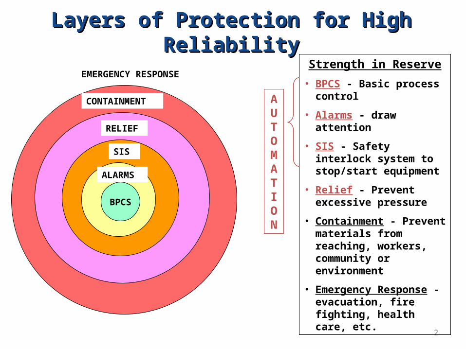
ALARMS
SIS
RELIEF
CONTAINMENT
EMERGENCY RESPONSE
BPCS
Strength in Reserve
• BPCS - Basic process control
• Alarms - draw attention
• SIS - Safety interlock system to stop/start equipment
• Relief - Prevent excessive pressure
• Containment - Prevent materials from reaching, workers, community or environment
• Emergency Response - evacuation, fire fighting, health care, etc.
AUTOMATION
Layers of Protection for High ReliabilityLayers of Protection for High Reliability

3
SAFETY STRENGTH IN DEPTH !
PROCESS
RELIEF SYSTEM
SAFETY INTERLOCK SYSTEM
ALARM SYSTEM
BASIC PROCESSCONTROL SYSTEM
Closed-loop control to maintain processwithin acceptable operating region
Bring unusual situation to attentionof a person in the plant
Stop the operation of part of process
Divert material safely
Seriousness of event
Four independent protection layers (IPL)
In automation
Key Concept in process Safety: REDUNDANCYKey Concept in process Safety: REDUNDANCY
4
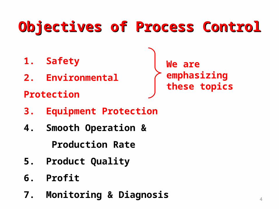
1. Safety
2. Environmental Protection
3. Equipment Protection
4. Smooth Operation &
Production Rate
5. Product Quality
6. Profit
7. Monitoring & Diagnosis
We are emphasizing these topics
Objectives of Process ControlObjectives of Process Control

5
• First line of defense
• Process control maintains variables at set points, which are fixed at some desired values
• Technology - Multiple PIDs, cascade, feedforward, etc.
• Guidelines
• Always control unstable variables (Examples in flash?)
• Always control “quick” safety related variables
Stable variables that tend to change quickly (Examples?)
• Monitor variables that change very slowly
Corrosion, erosion, build up of materials
• Provide safe response to critical instrumentation failures
- But, we use instrumentation in the BPCS?
Basic Process Control System (BPCS)Basic Process Control System (BPCS)
6
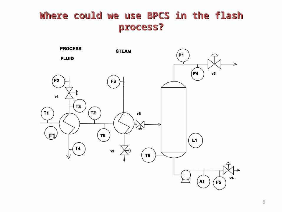
F1
Where could we use BPCS in the flash process?Where could we use BPCS in the flash process?

7
The level is unstable; it must be controlled.
The pressure will change quickly and affect safety; it must be controlled.
F1

8
• Alarm has an anunciator and visual indication
- No action is automated!
- require analysis by a person - A plant operator must decide.
• Digital computer stores a record of recent alarms
• Alarms should catch sensor failures
- But, sensors are used to measure variables for alarm checking?
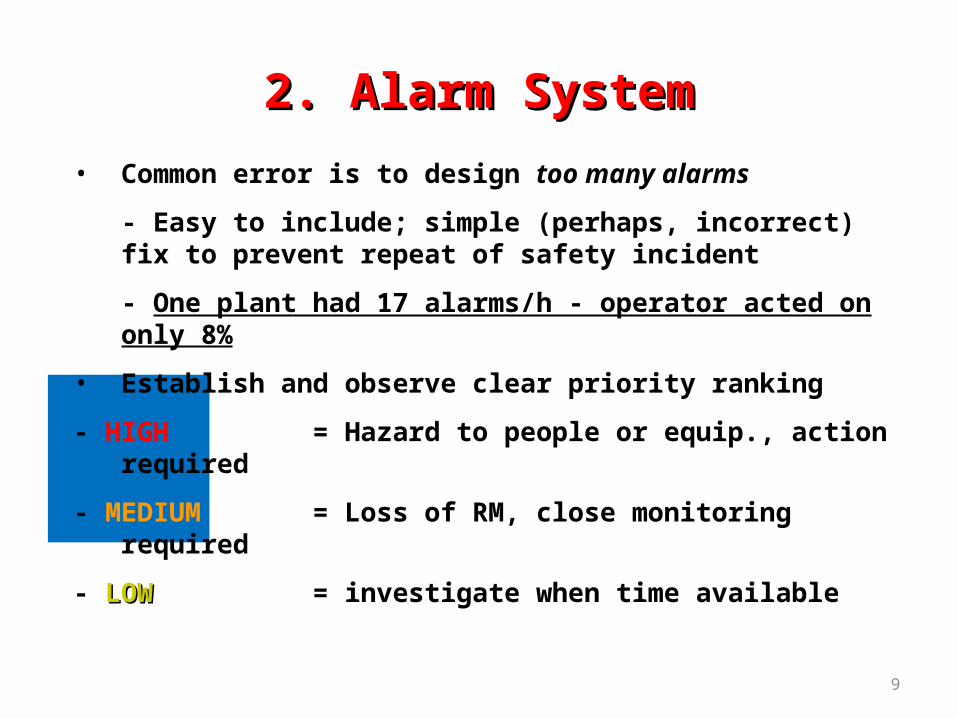
2. Alarm System2. Alarm System
9
• Common error is to design too many alarms
- Easy to include; simple (perhaps, incorrect) fix to prevent repeat of safety incident
- One plant had 17 alarms/h - operator acted on only 8%
• Establish and observe clear priority ranking
- HIGH = Hazard to people or equip., action required
- MEDIUM = Loss of RM, close monitoring required
- LOWLOW = investigate when time available
2. Alarm System2. Alarm System

10
F1
Where could we use alarm in the Flash Where could we use alarm in the Flash Process ?Process ?
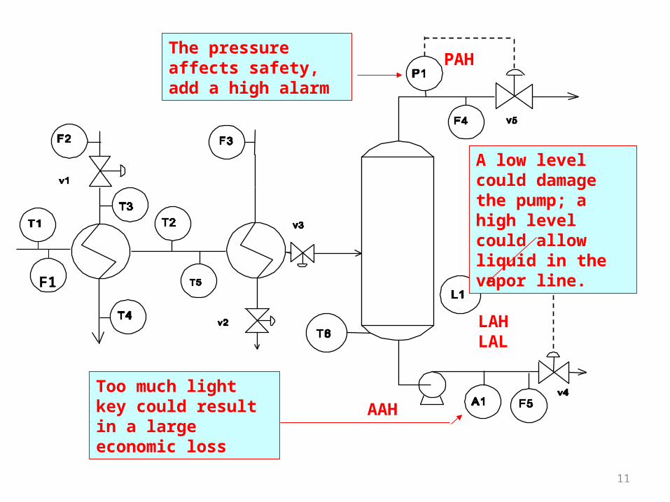
11
A low level could damage the pump; a high level could allow liquid in the vapor line.
The pressure affects safety, add a high alarm
F1
PAH
LAHLAL
Too much light key could result in a large economic loss
AAH
12
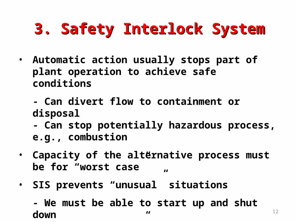
• Automatic action usually stops part of plant operation to achieve safe conditions
- Can divert flow to containment or disposal- Can stop potentially hazardous process, e.g., combustion
• Capacity of the alternative process must be for “worst case”
• SIS prevents “unusual” situations
- We must be able to start up and shut down- Very fast “blips” might not be significant
3. Safety Interlock System3. Safety Interlock System

13
• Also called emergency shutdown system (ESS)
• SIS should respond properly to instrumentation failures
- But, instrumentation is required for SIS?
• Extreme corrective action is required and automated
- More aggressive than process control (BPCS)
• Alarm to operator when an SIS takes action
3. Safety Interlock System3. Safety Interlock System
14
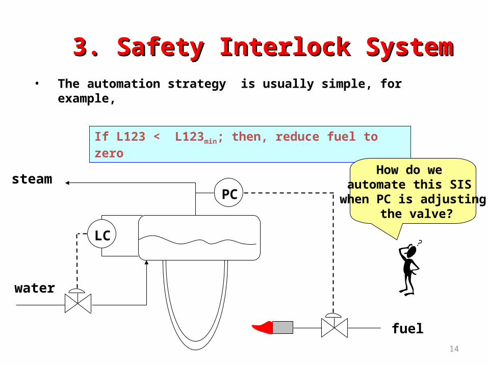
• The automation strategy is usually simple, for example,
If L123 < L123min; then, reduce fuel to zero
steam
water
LC
PC
fuel
How do we automate this SIS
when PC is adjusting the valve?
3. Safety Interlock System3. Safety Interlock System

15
If L123 < L123min; then, reduce fuel to zero
steam
water
LC
PC
fuel
LS s s
fc fc
15 psig
LS = level switch, note that separate sensor is used
s = solenoid valve (open/closed) fc = fail closed
Extra valve with tight shutoff

16
• The automation strategy may involve several variables, any one of which could activate the SIS
If L123 < L123min; orIf T105 > T105max
…….then, reduce fuel to zero
SIS100
L123T105…..
s
Shown as “box” in drawing with details elsewhere
3. Interlock System3. Interlock System
17
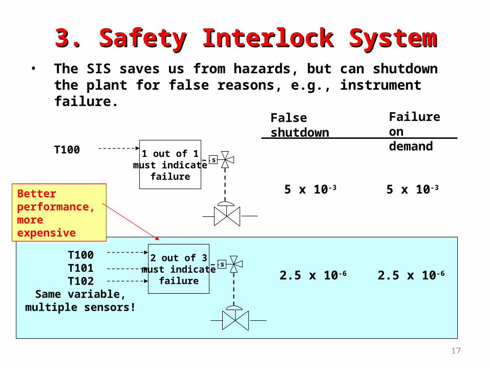
• The SIS saves us from hazards, but can shutdown the plant for false reasons, e.g., instrument failure.
1 out of 1 must indicate
failure
T100s
2 out of 3 must indicate
failure
T100T101T102
Same variable,multiple sensors!
s
Falseshutdown
Failure on demand
5 x 10-35 x 10-3
2.5 x 10⁻⁶ 2.5 x 10⁻⁶
Better performance,more expensive
3. Safety Interlock System3. Safety Interlock System

18
• We desire independent protection layers, without common-cause failures - Separate systems
sensors
SIS system
i/o i/o………….
sensors
Digital control system
i/o i/o………….
BPCS and Alarms SIS and Alarms associated with SIS
3. Safety Interlock System3. Safety Interlock System
19
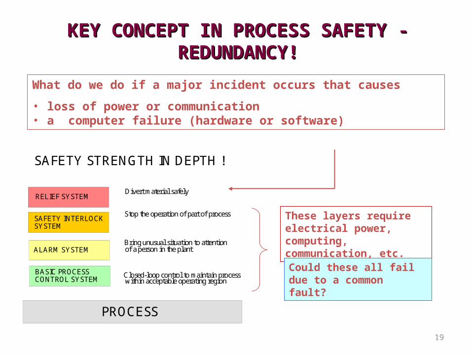
SAFETY STRENGTH IN DEPTH !
PROCESS
RELIEF SYSTEM
SAFETY INTERLOCK SYSTEM
ALARM SYSTEM
BASIC PROCESSCONTROL SYSTEM
Closed-loop control to maintain processwithin acceptable operating region
Bring unusual situation to attentionof a person in the plant
Stop the operation of part of process
Divert material safely
These layers require electrical power, computing, communication, etc.
KEY CONCEPT IN PROCESS SAFETY - KEY CONCEPT IN PROCESS SAFETY - REDUNDANCY!REDUNDANCY!
What do we do if a major incident occurs that causes
• loss of power or communication• a computer failure (hardware or software)
Could these all fail due to a common fault?

20
• Entirely self-contained, no external power required
• The action is automatic - does not require a person
• Usually, goal is to achieve reasonable pressure
- Prevent high (over-) pressure- Prevent low (under-) pressure
• The capacity should be for the “worst case” scenario
4. Safety Relief System4. Safety Relief System

21
• Increase in pressure can lead to rupture of vessel or pipe and release of toxic or flammable material
•• - Also, we must protect against unexpected vacuum!
• Naturally, best to prevent the pressure increase
• - large disturbances, equipment failure, human error, power failure, ...
• Relief systems provide an exit path for fluid
• Benefits: safety, environmental protection, equipment protection, reduced insurance, compliance with governmental code
RELIEF SYSTEMS IN PROCESS PLANTSRELIEF SYSTEMS IN PROCESS PLANTS
22
Identify potential for damage due to high (or low) pressure (HAZOP Study)
In general, closed volume with ANY potential for pressure increase
- may have exit path that should not be closed but could be- hand valve, control valve (even fail open), blockage of line
Remember, this is the last resort, when all other safety systems have not been adequate and a fast response is required!
Location of Relief SystemLocation of Relief System
23
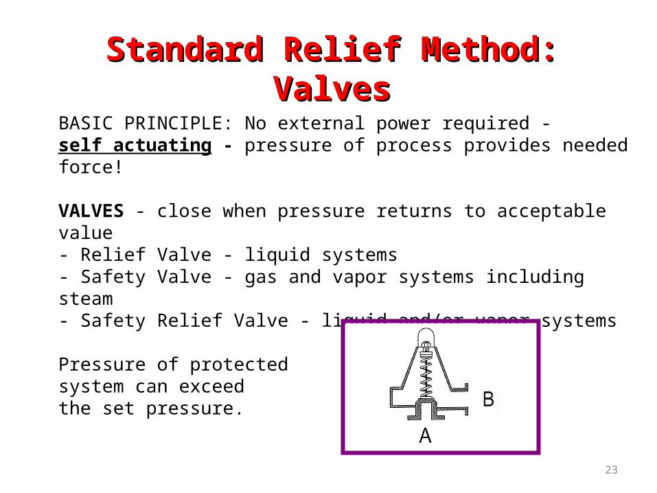
BASIC PRINCIPLE: No external power required - self actuating - pressure of process provides needed force!
VALVES - close when pressure returns to acceptable value- Relief Valve - liquid systems- Safety Valve - gas and vapor systems including steam- Safety Relief Valve - liquid and/or vapor systems
Pressure of protected system can exceed the set pressure.
Standard Relief Method: ValvesStandard Relief Method: Valves

24
BASIC PRINCIPLE: No external power required - self acting
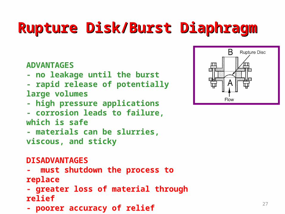
RUPTURE DISKS OR BURST DIAPHRAGMS - must be replaced after opening
.
Standard Relief Method: Rupture DiskStandard Relief Method: Rupture Disk

25
Two types of designs determine influence of pressure immediately after the valve
- Conventional Valve -pressure after the valve affects the valve lift and opening- Balanced Valve - pressure after the valve does not affect the valve lift and opening
Conventional Balanced
Relief ValvesRelief Valves
26
ADVANTAGES
- simple, low cost and many commercial designs available- regain normal process operation rapidly because the valve closes when pressure decreases below set value
DISADVANTAGES
- can leak after once being open (O-ring reduces)- not for very high pressures (20,000 psi)- if oversized, can lead to damage and failure (do not be too conservative; the very large valve is not the safest!)
Some Information about Relief Valves Some Information about Relief Valves
27
ADVANTAGES- no leakage until the burst- rapid release of potentially large volumes - high pressure applications- corrosion leads to failure, which is safe- materials can be slurries, viscous, and sticky
DISADVANTAGES- must shutdown the process to replace- greater loss of material through relief- poorer accuracy of relief pressure the valve
Rupture Disk/Burst DiaphragmRupture Disk/Burst Diaphragm

28
• Spring-loaded safety relief valve
Process
To effluent handling
• Rupture disc
Process To effluent handling
Symbols used in P&I DSymbols used in P&I D
29
F1
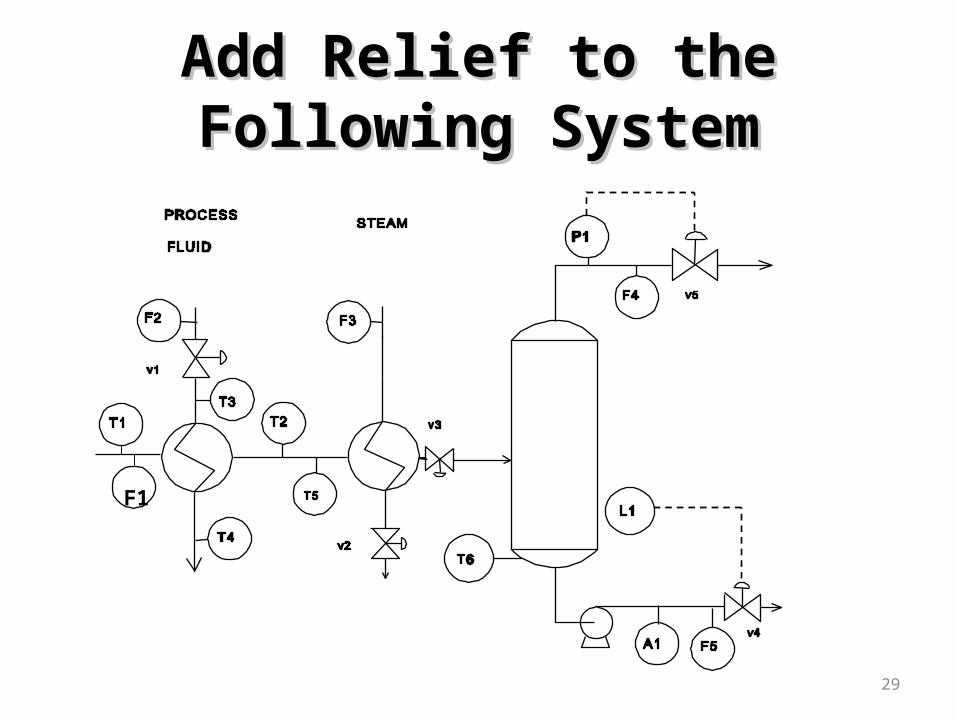
Add Relief to the Following Add Relief to the Following SystemSystem

30
F1
The drum can be isolated with the control valves; pressure relief is required.
We would like to recover without shutdown; we select a relief valve.
Add Relief to the Following Add Relief to the Following SystemSystem
31
Positive displacement pump
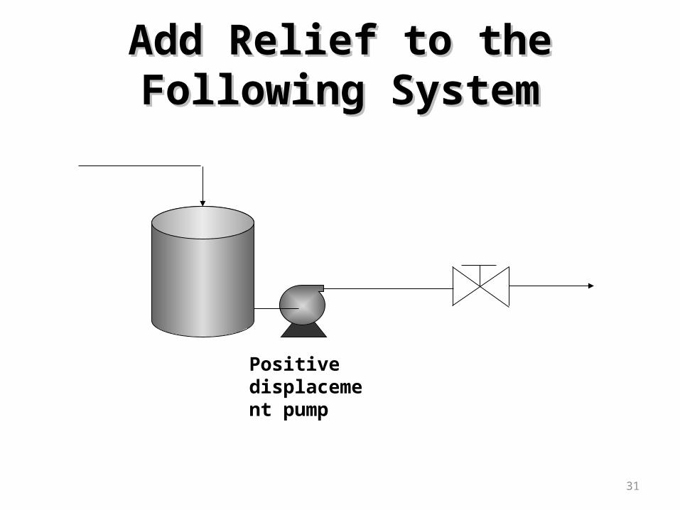
Add Relief to the Following Add Relief to the Following SystemSystem
32
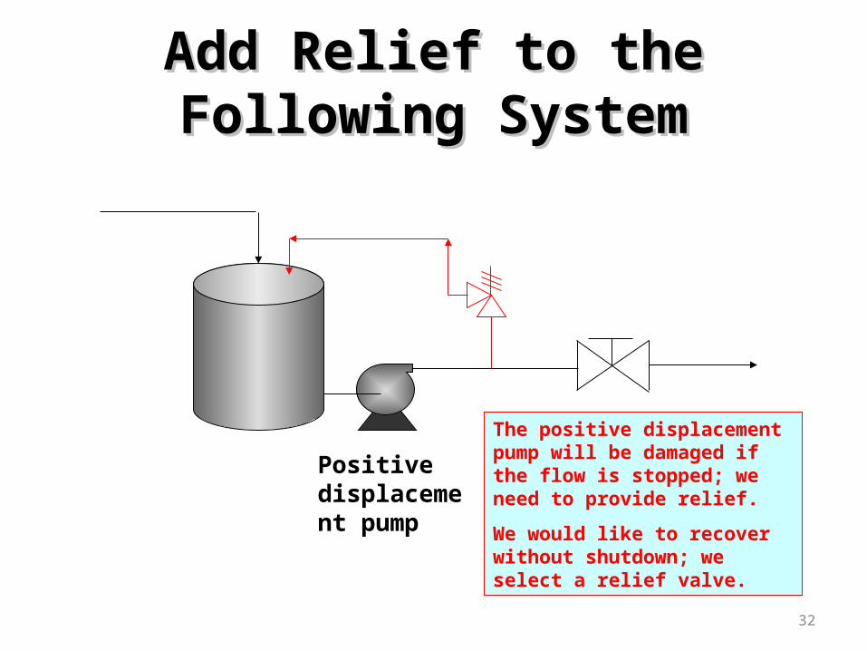
Positive displacement pump
The positive displacement pump will be damaged if the flow is stopped; we need to provide relief.
We would like to recover without shutdown; we select a relief valve.
Add Relief to the Following Add Relief to the Following SystemSystem

33
Why are all those valves
in the process?
Add Relief to the Following SystemAdd Relief to the Following System
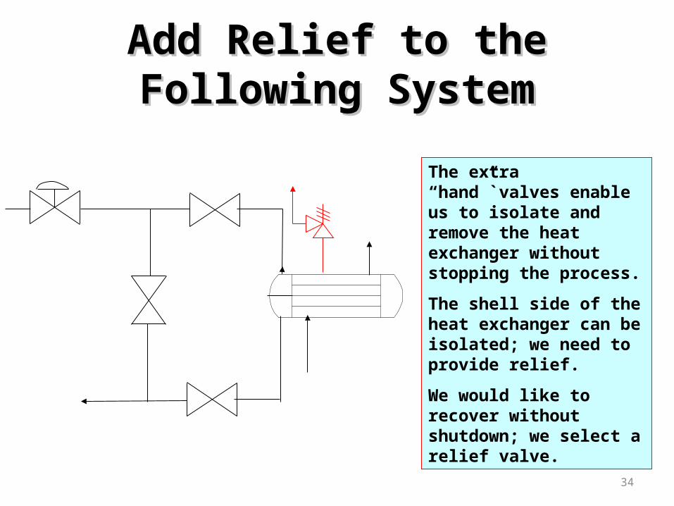
34
The extra “hand”`valves enable us to isolate and remove the heat exchanger without stopping the process.
The shell side of the heat exchanger can be isolated; we need to provide relief.
We would like to recover without shutdown; we select a relief valve.
Add Relief to the Following Add Relief to the Following SystemSystem

35
Why is the pressure indicator provided?
Is it local or remotely displayed? Why?
• What is the advantage of two in series?
• Why not have two relief valves (diaphragms) in series?
In some cases, relief and diaphragm are used In some cases, relief and diaphragm are used in series – WHY?in series – WHY?
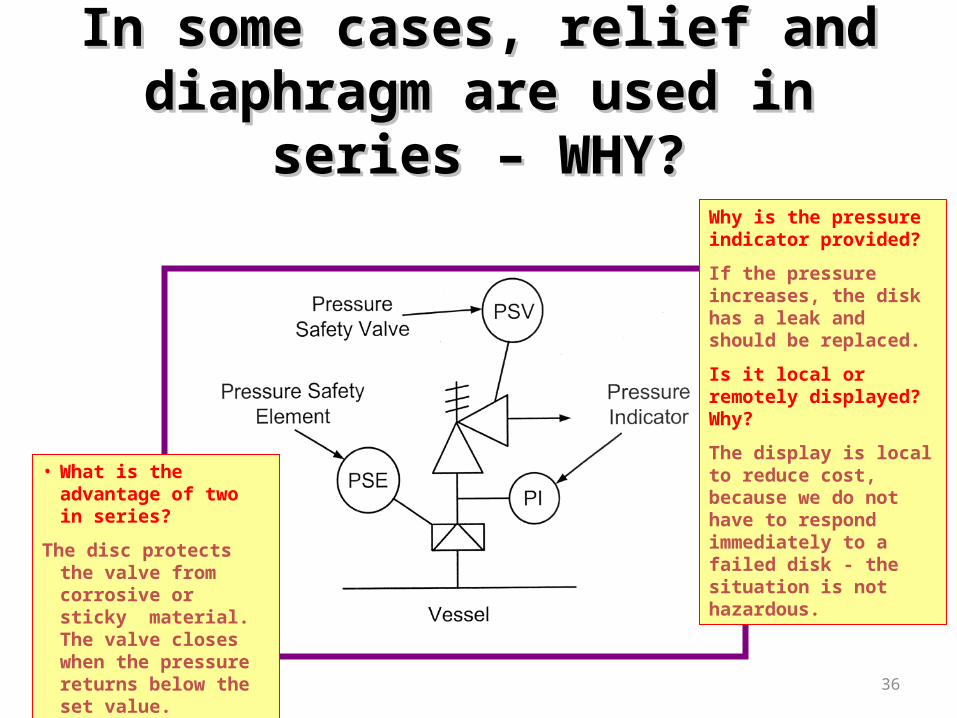
36
Why is the pressure indicator provided?
If the pressure increases, the disk has a leak and should be replaced.
Is it local or remotely displayed? Why?
The display is local to reduce cost, because we do not have to respond immediately to a failed disk - the situation is not hazardous.
• What is the advantage of two in series?
The disc protects the valve from corrosive or sticky material. The valve closes when the pressure returns below the set value.
In some cases, relief and diaphragm In some cases, relief and diaphragm are used in series – WHY?are used in series – WHY?

37
Structure vent closed
Structure
explosion
Vents required to control or direct Vents required to control or direct vapour/dust explosion effectvapour/dust explosion effect

38
From relief
To environment Vent steam, air
Holding for later processing Waste water treating
Recycle to process Fuel gas, fuel oil, solvent
Recover part to process
Immediate neutralization Flare, toxic materials
Materials from relief must be Materials from relief must be process or dispose safelyprocess or dispose safely
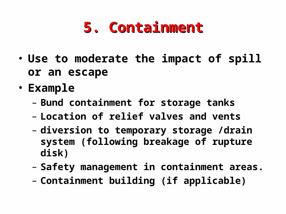
5. Containment5. Containment
• Use to moderate the impact of spill or an escape
• Example– Bund containment for storage tanks– Location of relief valves and vents – diversion to temporary storage /drain system
(following breakage of rupture disk)– Safety management in containment areas.– Containment building (if applicable)

6. Emergency Response 6. Emergency Response Management Management
• Also used to moderate impact on incidents• All plants should ERP (emergency response
plan)– Assembly, head-counts, evacuation etc…
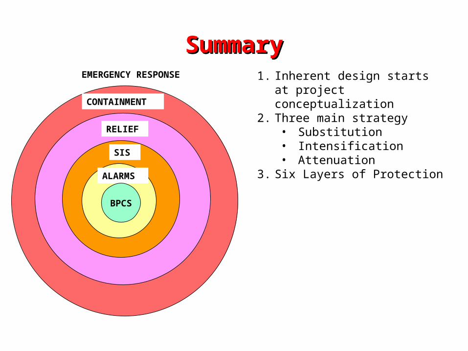
SummarySummary
ALARMS
SIS
RELIEF
CONTAINMENT
EMERGENCY RESPONSE
BPCS
1. Inherent design starts at project conceptualization
2. Three main strategy• Substitution• Intensification• Attenuation
3. Six Layers of Protection


