39
31 October 2013 Instrument Transformer - Technology & Design Conference on Electrical Power Equipment Diagnostics Bali, Indonesia Thomas Prevost
31 October 2013
Instrument Transformer - Technology & Design Conference on Electrical Power Equipment Diagnostics Bali, Indonesia Thomas Prevost
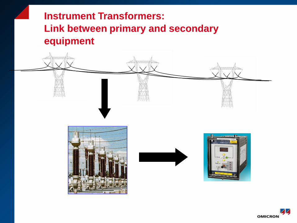
Instrument Transformers: Link between primary and secondary equipment
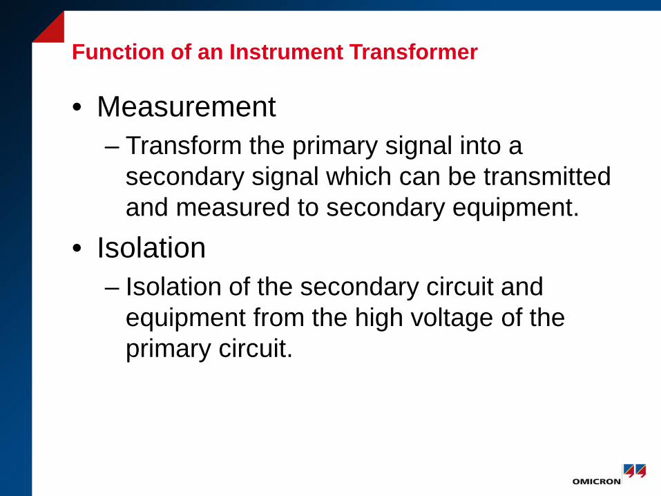
Function of an Instrument Transformer
• Measurement – Transform the primary signal into a
secondary signal which can be transmitted and measured to secondary equipment.
• Isolation – Isolation of the secondary circuit and
equipment from the high voltage of the primary circuit.
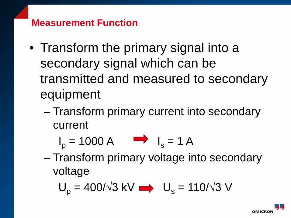
Measurement Function • Transform the primary signal into a
secondary signal which can be transmitted and measured to secondary equipment – Transform primary current into secondary
current Ip = 1000 A Is = 1 A – Transform primary voltage into secondary
voltage Up = 400/√3 kV Us = 110/√3 V
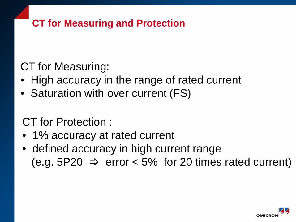
CT for Measuring and Protection
CT for Measuring: • High accuracy in the range of rated current • Saturation with over current (FS)
CT for Protection : • 1% accuracy at rated current • defined accuracy in high current range (e.g. 5P20 error < 5% for 20 times rated current)
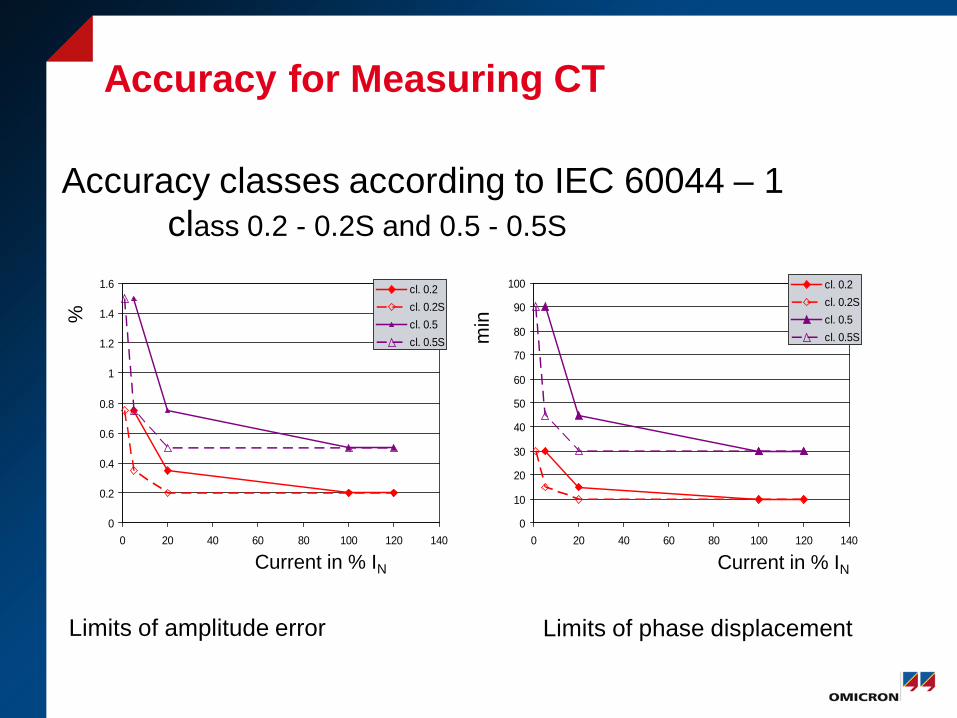
Accuracy for Measuring CT
0
0.2
0.4
0.6
0.8
1
1.2
1.4
1.6
0 20 40 60 80 100 120 140
cl. 0.2cl. 0.2Scl. 0.5cl. 0.5S
Accuracy classes according to IEC 60044 – 1 class 0.2 - 0.2S and 0.5 - 0.5S
Limits of amplitude error
Limits of phase displacement
Current in % IN Current in % IN
%
min
0
10
20
30
40
50
60
70
80
90
100
0 20 40 60 80 100 120 140
cl. 0.2cl. 0.2Scl. 0.5cl. 0.5S
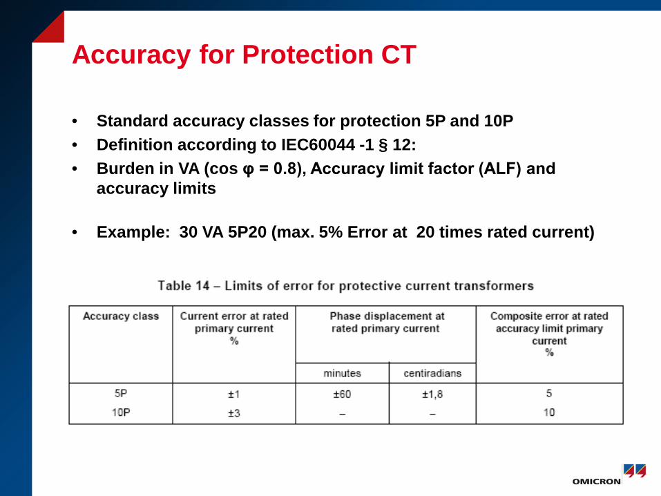
Accuracy for Protection CT
• Standard accuracy classes for protection 5P and 10P • Definition according to IEC60044 -1 § 12: • Burden in VA (cos φ = 0.8), Accuracy limit factor (ALF) and
accuracy limits
• Example: 30 VA 5P20 (max. 5% Error at 20 times rated current)
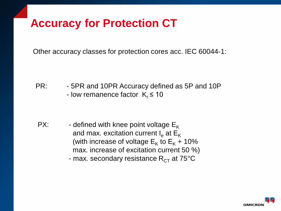
Accuracy for Protection CT
Other accuracy classes for protection cores acc. IEC 60044-1:
PR: - 5PR and 10PR Accuracy defined as 5P and 10P - low remanence factor Kr ≤ 10
PX: - defined with knee point voltage EK and max. excitation current Ie at EK (with increase of voltage EK to EK + 10% max. increase of excitation current 50 %) - max. secondary resistance RCT at 75°C
Accuracy for Protection CT
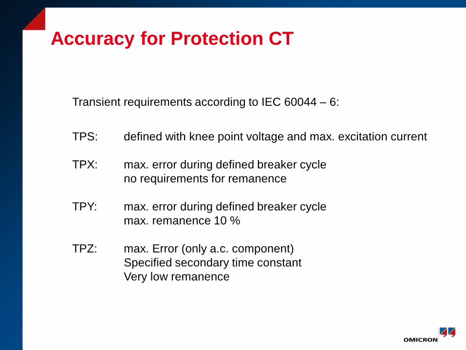
Transient requirements according to IEC 60044 – 6:
TPS: defined with knee point voltage and max. excitation current TPX: max. error during defined breaker cycle no requirements for remanence TPY: max. error during defined breaker cycle max. remanence 10 % TPZ: max. Error (only a.c. component) Specified secondary time constant Very low remanence
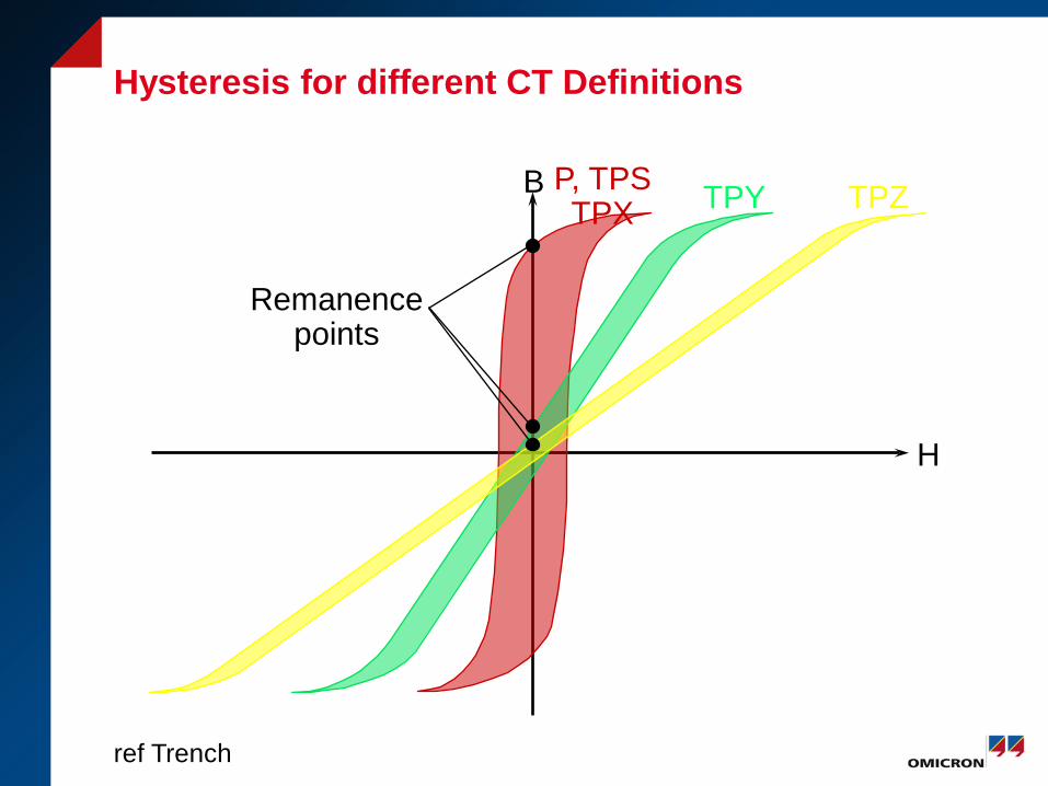
Hysteresis for different CT Definitions
B
H
P, TPS TPX TPY TPZ
Remanence points
ref Trench
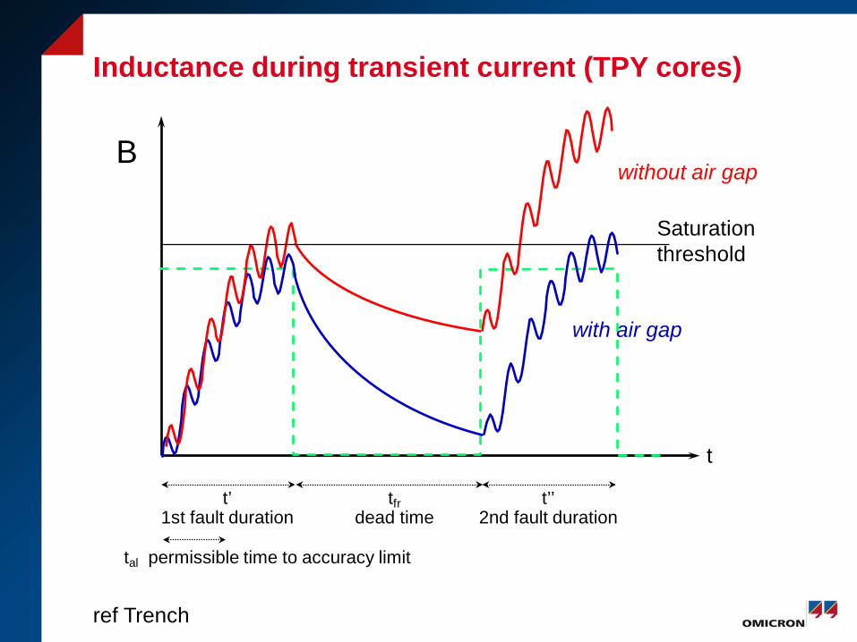
Inductance during transient current (TPY cores)
t
t’ 1st fault duration
t’’ 2nd fault duration
tfr dead time
tal permissible time to accuracy limit
with air gap
without air gap B
Saturation threshold
ref Trench
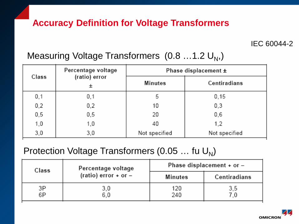
Accuracy Definition for Voltage Transformers
IEC 60044-2
Measuring Voltage Transformers (0.8 …1.2 UN,)
Protection Voltage Transformers (0.05 … fu UN)
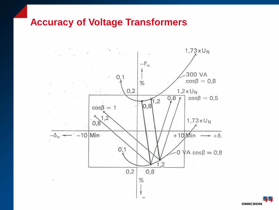
Accuracy of Voltage Transformers
Function of an Instrument Transformer
• Measurement – Transform the primary signal into a
secondary signal which can be transmitted and measured to secondary equipment.
• Isolation – Isolation of the secondary circuit and
equipment from the high voltage of the primary circuit.
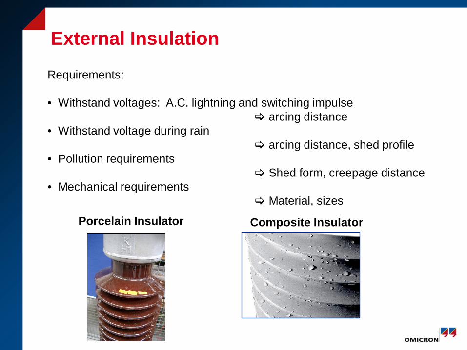
External Insulation
Requirements: • Withstand voltages: A.C. lightning and switching impulse arcing distance • Withstand voltage during rain arcing distance, shed profile • Pollution requirements Shed form, creepage distance • Mechanical requirements
Material, sizes
Porcelain Insulator Composite Insulator
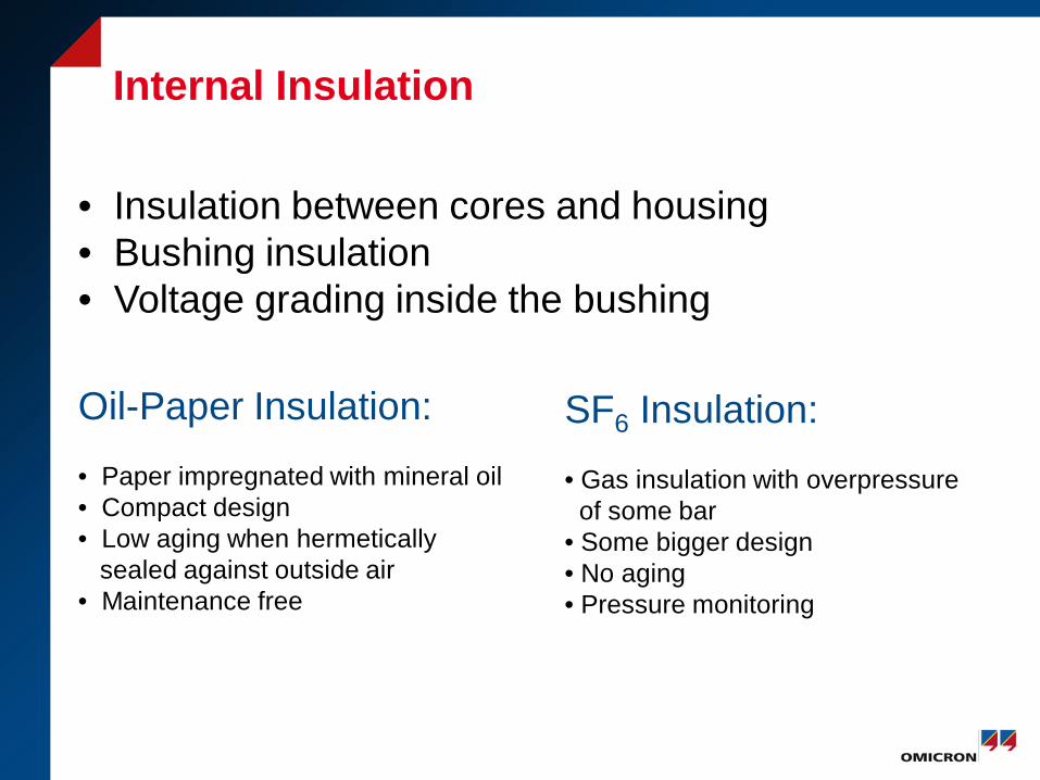
Internal Insulation
• Insulation between cores and housing • Bushing insulation • Voltage grading inside the bushing
Oil-Paper Insulation: • Paper impregnated with mineral oil • Compact design • Low aging when hermetically sealed against outside air • Maintenance free
SF6 Insulation: • Gas insulation with overpressure of some bar • Some bigger design • No aging • Pressure monitoring
Conventional Instrument Transformers Inductive principle

Current Transformer
Oil-Paper Insulation 72.5 kV … 550 kV
SF6 Insulation 72.5 kV … 800 kV
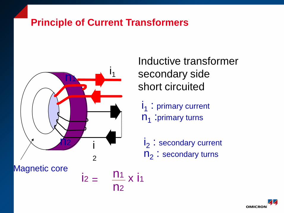
Principle of Current Transformers
i2 = x i1 n1
n2
n1
n2
Magnetic core
i1
i2
Inductive transformer secondary side short circuited
i1 : primary current n1 :primary turns
i2 : secondary current n2 : secondary turns
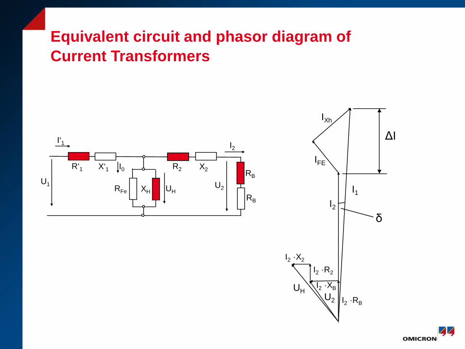
Equivalent circuit and phasor diagram of Current Transformers
R‘1 X‘1
RFe
R2 X2 RB
RB
XH
U1 UH U2
I0
I2 I‘1
IXh
I1
IFE
I2
UH U2 I2 ·RB
I2 ·XB
I2 ·R2
I2 ·X2
δ
ΔI
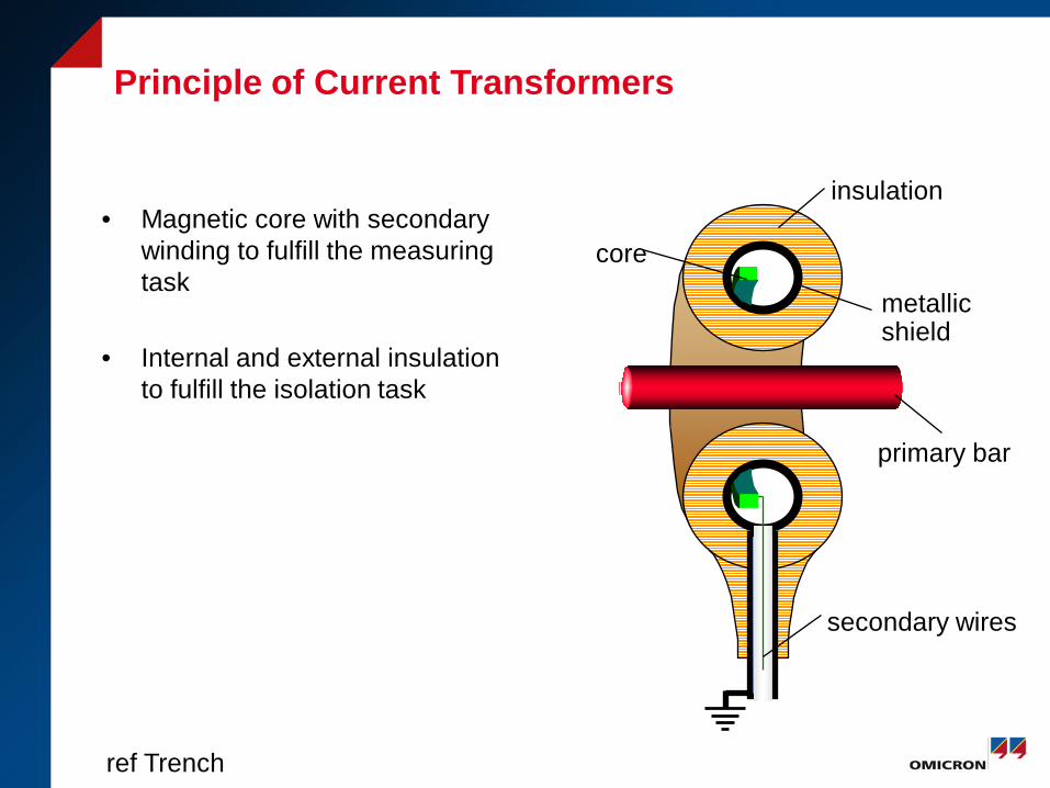
Principle of Current Transformers
• Magnetic core with secondary winding to fulfill the measuring task
• Internal and external insulation to fulfill the isolation task
primary bar
insulation
metallic shield
secondary wires
core
ref Trench
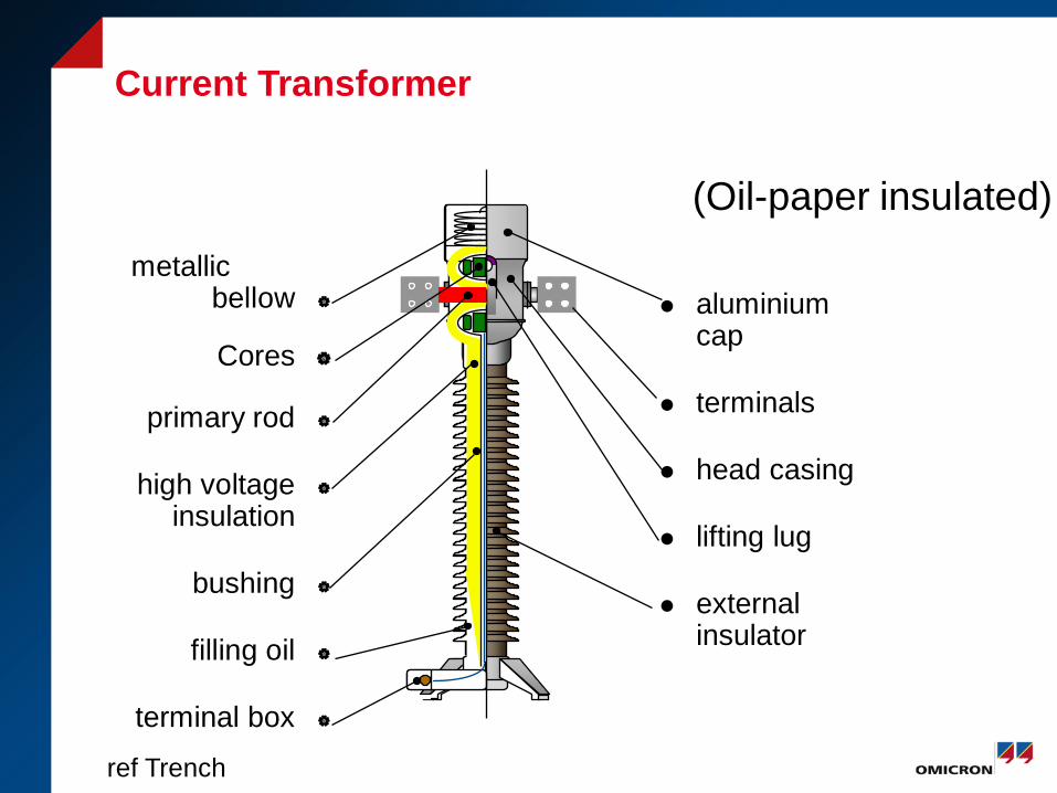
Current Transformer
aluminium cap
terminals
head casing
lifting lug
external insulator
metallic bellow
Cores
primary rod
high voltage
insulation
bushing
filling oil
terminal box
(Oil-paper insulated)
ref Trench
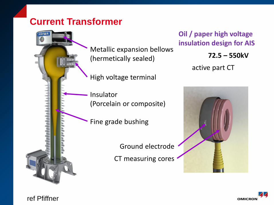
72.5 – 550kV
High voltage terminal
Insulator (Porcelain or composite)
Metallic expansion bellows (hermetically sealed)
Fine grade bushing
active part CT
Ground electrode
CT measuring cores
Oil / paper high voltage insulation design for AIS
Current Transformer
ref Pfiffner
Current Transformer
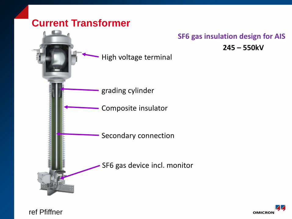
245 – 550kV High voltage terminal
Composite insulator
grading cylinder
Secondary connection
SF6 gas device incl. monitor
SF6 gas insulation design for AIS Current Transformer
ref Pfiffner
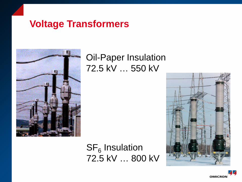
Voltage Transformers
Oil-Paper Insulation 72.5 kV … 550 kV
SF6 Insulation 72.5 kV … 800 kV

Principle Voltage Transformers
u1, n1
u2, n2
u2 = x u1 n2
n1
insulation
Secondary windings
iron core
Primary winding
bushing
high voltage
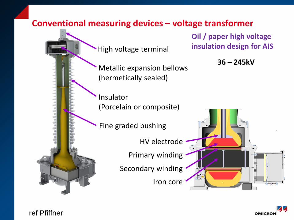
High voltage terminal
Metallic expansion bellows (hermetically sealed)
Insulator (Porcelain or composite)
Fine graded bushing
HV electrode
Primary winding
Secondary winding
Iron core
Oil / paper high voltage insulation design for AIS
36 – 245kV
Conventional measuring devices – voltage transformer
ref Pfiffner

Equivalent Circuit and phasor diagram of Voltage Transformers
R‘1 X‘1
RFe
R2 X2 RB
XB
XH
U1 UH U2
I0
I2 I‘1 U1
U2
UH
IFe
IXh
I2 I‘1
I2·RB
I2·XB
I2·R2
I2·X2
I‘1·R’1
I‘1·X’1
δ
ΔU
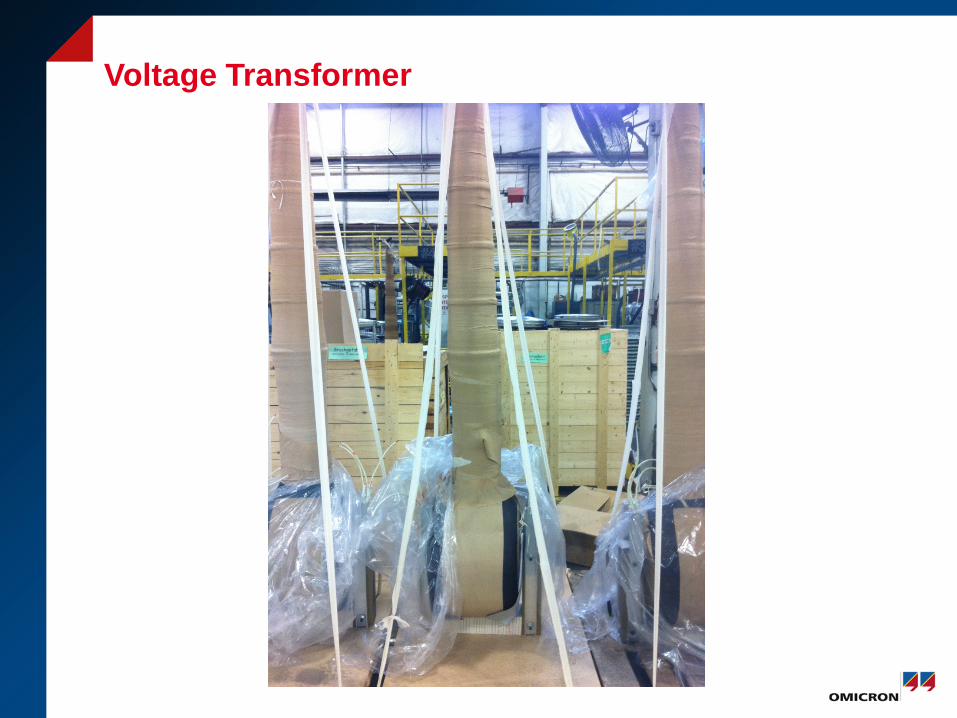
Voltage Transformer
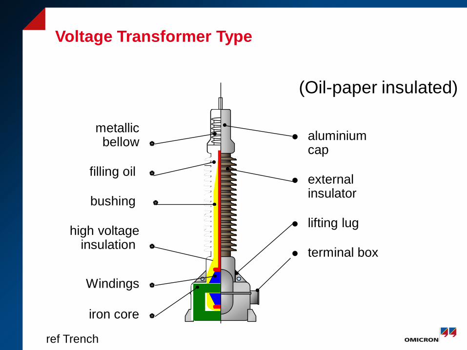
Voltage Transformer Type
aluminium cap
external insulator
lifting lug
terminal box
metallic bellow
filling oil
bushing
high voltage insulation
Windings
iron core
(Oil-paper insulated)
ref Trench

Gas insulated Voltage Transformers
GIF-outdoor voltage transformer
HV-electrode
GIS-voltage transformer
HV-spacer
pressure vessel
rupture disk
LV - winding
ref Trench
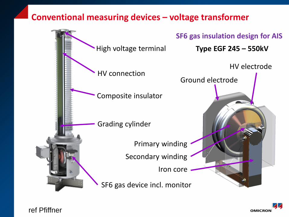
Conventional measuring devices – voltage transformer
High voltage terminal
Composite insulator
Grading cylinder
HV connection
SF6 gas insulation design for AIS
Primary winding
Secondary winding
Iron core
Ground electrode
HV electrode
Type EGF 245 – 550kV
SF6 gas device incl. monitor
ref Pfiffner
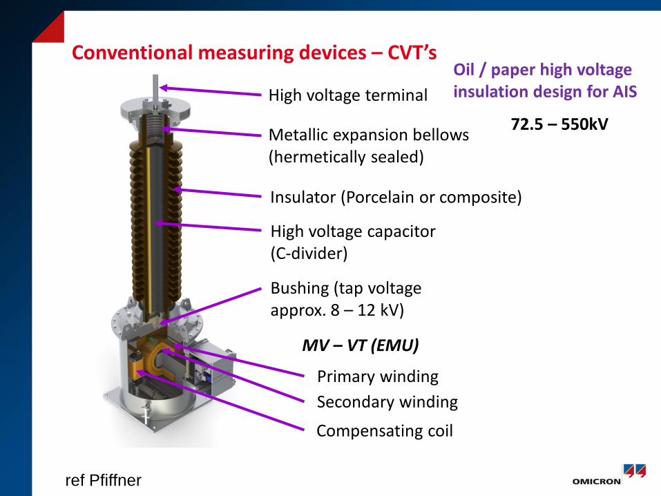
High voltage terminal
Metallic expansion bellows (hermetically sealed)
Insulator (Porcelain or composite)
High voltage capacitor (C-divider)
Bushing (tap voltage approx. 8 – 12 kV)
MV – VT (EMU)
Secondary winding Primary winding
Compensating coil
72.5 – 550kV
Oil / paper high voltage insulation design for AIS
Conventional measuring devices – CVT’s
ref Pfiffner

primary terminal
lifting lug
head
porcelain insulator
housing
terminal box
Housing
metallic bellow
capacitor
intermediate transformer + compensating coil
Active part
Capacitive Voltage Transformer
ref Trench
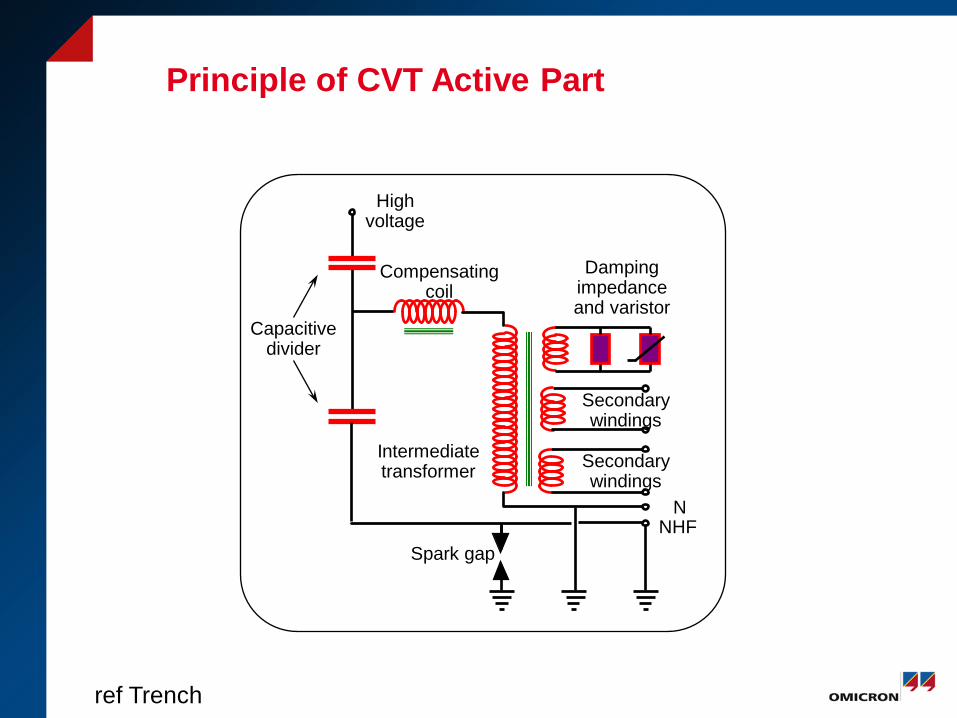
Principle of CVT Active Part
Intermediate transformer
Compensating coil
Secondary windings
Secondary windings
N
Damping impedance and varistor
Spark gap NHF
High voltage
Capacitive divider
ref Trench
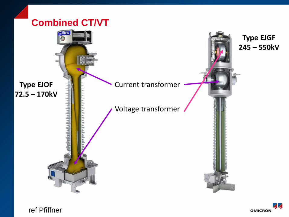
Combined CT/VT Type EJGF
245 – 550kV
Type EJOF 72.5 – 170kV
Current transformer
Voltage transformer
ref Pfiffner
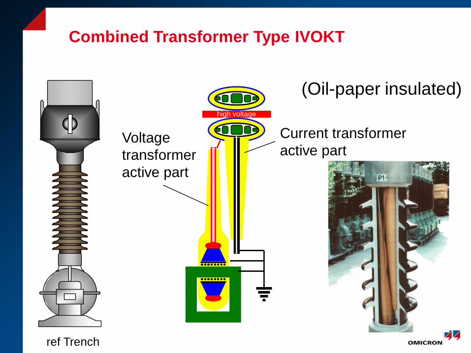
Combined Transformer Type IVOKT
high voltage
Current transformer active part
Voltage transformer active part
(Oil-paper insulated)
ref Trench

Questions


