16 th HAPL Meeting Princeton, New Jersey December 12, 2006 Naval Research Laboratory Plasma Physics Division Washington, DC Presented by M. Wolford Work supported by DOE/NNSA/DP Electra (KrF) Laser Development NRL J. Sethian M. Myers J. Giuliani M. Wolford S. Obenschain Commonwealth Tech F. Hegeler M. Friedman T. Albert J. Parrish K. Gunlicks RSI P. Burns R. Lehmberg S. Searles SAIC R. Jaynes
Transcript
16th HAPL MeetingPrinceton, New Jersey
December 12, 2006
Naval Research LaboratoryPlasma Physics Division
Washington, DC
Presented by M. Wolford
Work supported by DOE/NNSA/DP
Electra (KrF) Laser Development
NRLJ. SethianM. MyersJ. GiulianiM. Wolford S. Obenschain
Commonwealth Tech
F. HegelerM. Friedman
T. Albert J. Parrish K. Gunlicks
RSIP. Burns
R. Lehmberg S. Searles
SAIC R. Jaynes
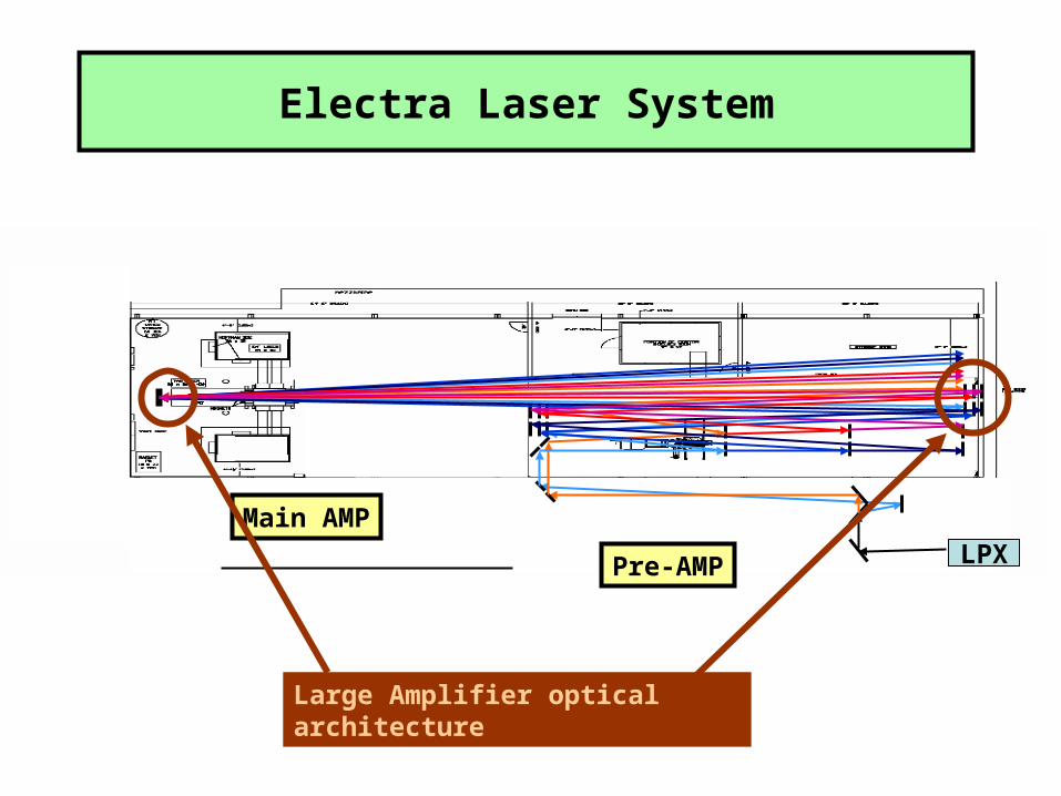
• Starting Integration of Electra Laser System– First Stages of Construction
• Pre-Amplifier Laser Energy Measurements– Increased laser yield to 25 J– Time-Dependent characterization of laser pulse– Near-Field Profile
• Foil failure due to debris and/or plasma arcs in A-K gap
Previous Limits to Laser Durability(< 10 k shots)
March 2006 HAPL meeting
Hibachi
Solved with new all-carbon emitter.As much as 25 k shots
(reported at Aug 2006 meeting)Foil
MAY have been solved withhigh transparency anode screen
Screen
One Possible mechanism limiting foil durabilityElectron emission from Anode
Hypothesis Rationale
Micro particles can stick to the foil Emission is an explosive process.See marks on foil
Voltage reverses in diode Seen on Voltage monitorsafter the main pulse
Voltage reversal causes micro See what may be "cathode spots" onparticles to emit electrons pressure foil
Emission can be an explosive process Known fact.
Can puncture hole in highly stressed Experiments with an anode foil showpressure foil evolution of this process
First experiments with mesh, (90%-95% effective transmission) showa) Minimal degradation in laser energy (i.e. transmission OK)b) First Implementation lasted several multi-thousand shot runs
• Starting Integration of Electra Laser System– First Stages of Construction
• Pre-Amplifier Laser Energy Measurements– Increased laser yield to 25 J– Time-Dependent characterization of laser pulse– Near-Field Profile