Encore r HD Pump Control Unit and Power Supply Customer Product Manual Part 1606783-06 Issued 6/19 NORDSON CORPORATION • AMHERST, OHIO • USA For parts and technical support, call the Industrial Coating Systems Customer Support Center at (800) 433-9319 or contact your local Nordson representative. This document is subject to change without notice. Check http://emanuals.nordson.com for the latest version and available local languages.
Transcript
Encore� HD Pump Control Unit andPower Supply
Customer Product ManualPart 1606783-06
Issued 6/19
NORDSON CORPORATION • AMHERST, OHIO • USA
For parts and technical support, call the Industrial CoatingSystems Customer Support Center at (800) 433-9319 or
contact your local Nordson representative.
This document is subject to change without notice.Check http://emanuals.nordson.com for the latest version
and available local languages.
Part 1606783−06 � 2019 Nordson Corporation
Contact UsNordson Corporation welcomes requests for information, comments, andinquiries about its products. General information about Nordson can befound on the Internet using the following address:http://www.nordson.com.Address all correspondence to:
Nordson CorporationAttn: Customer Service555 Jackson StreetAmherst, OH 44001
NoticeThis is a Nordson Corporation publication which is protected by copyright.Original copyright date 2015. No part of this document may bephotocopied, reproduced, or translated to another language without theprior written consent of Nordson Corporation. The information containedin this publication is subject to change without notice.
Trademarks
Encore, iFlow, Nordson and the Nordson logo are registered trademarksof Nordson Corporation.
All other trademarks are the property of their respective owners.
04 1/18 Updated for new Encore HD pump information.
05 11/18 Replacing part number 1606690 with 1615026
06 6/19 Update part lists for pump control, panel assembly, manifold assembly,pump, spare parts, powder hose and air tubing.
Change Recordii
Part 1606783−06 � 2019 Nordson Corporation
Safety 1-1
Part 1606783−06� 2019 Nordson Corporation
Section 1Safety
Introduction Read and follow these safety instructions. Task- and equipment-specificwarnings, cautions, and instructions are included in equipmentdocumentation where appropriate.
Make sure all equipment documentation, including these instructions, isaccessible to all persons operating or servicing equipment.
Qualified Personnel Equipment owners are responsible for making sure that Nordson equipmentis installed, operated, and serviced by qualified personnel. Qualifiedpersonnel are those employees or contractors who are trained to safelyperform their assigned tasks. They are familiar with all relevant safety rulesand regulations and are physically capable of performing their assignedtasks.
Intended Use Use of Nordson equipment in ways other than those described in thedocumentation supplied with the equipment may result in injury to personsor damage to property.
Some examples of unintended use of equipment include
� using incompatible materials
� making unauthorized modifications
� removing or bypassing safety guards or interlocks
� using incompatible or damaged parts
� using unapproved auxiliary equipment
� operating equipment in excess of maximum ratings
Regulations and Approvals Make sure all equipment is rated and approved for the environment in whichit is used. Any approvals obtained for Nordson equipment will be voided ifinstructions for installation, operation, and service are not followed.
All phases of equipment installation must comply with all federal, state, andlocal codes.
Safety1-2
Part 1606783−06 � 2019 Nordson Corporation
Personal Safety To prevent injury follow these instructions.
� Do not operate or service equipment unless you are qualified.
� Do not operate equipment unless safety guards, doors, or covers areintact and automatic interlocks are operating properly. Do not bypass ordisarm any safety devices.
� Keep clear of moving equipment. Before adjusting or servicing anymoving equipment, shut off the power supply and wait until theequipment comes to a complete stop. Lock out power and secure theequipment to prevent unexpected movement.
� Relieve (bleed off) hydraulic and pneumatic pressure before adjusting orservicing pressurized systems or components. Disconnect, lock out,and tag switches before servicing electrical equipment.
� Obtain and read Safety Data Sheets (SDS) for all materials used.Follow the manufacturer’s instructions for safe handling and use ofmaterials, and use recommended personal protection devices.
� To prevent injury, be aware of less-obvious dangers in the workplacethat often cannot be completely eliminated, such as hot surfaces, sharpedges, energized electrical circuits, and moving parts that cannot beenclosed or otherwise guarded for practical reasons.
Fire Safety To avoid a fire or explosion, follow these instructions.
� Do not smoke, weld, grind, or use open flames where flammablematerials are being used or stored.
� Provide adequate ventilation to prevent dangerous concentrations ofvolatile materials or vapors. Refer to local codes or your material SDSfor guidance.
� Do not disconnect live electrical circuits while working with flammablematerials. Shut off power at a disconnect switch first to preventsparking.
� Know where emergency stop buttons, shutoff valves, and fireextinguishers are located. If a fire starts in a spray booth, immediatelyshut off the spray system and exhaust fans.
� Clean, maintain, test, and repair equipment according to the instructionsin your equipment documentation.
� Use only replacement parts that are designed for use with originalequipment. Contact your Nordson representative for parts informationand advice.
Safety 1-3
Part 1606783−06� 2019 Nordson Corporation
Grounding WARNING: Operating faulty electrostatic equipment is hazardous and cancause electrocution, fire, or explosion. Make resistance checks part of yourperiodic maintenance program. If you receive even a slight electrical shockor notice static sparking or arcing, shut down all electrical or electrostaticequipment immediately. Do not restart the equipment until the problem hasbeen identified and corrected.
Grounding inside and around the booth openings must comply with NFPArequirements for Class II, Division 1 or 2 Hazardous Locations. Refer toNFPA 33, NFPA 70 (NEC articles 500, 502, and 516), and NFPA 77, latestconditions.
� All electrically conductive objects in the spray areas shall be electricallyconnected to ground with a resistance of not more than 1 megohm asmeasured with an instrument that applies at least 500 volts to the circuitbeing evaluated.
� Equipment to be grounded includes, but is not limited to, the floor of thespray area, operator platforms, hoppers, photoeye supports, andblow-off nozzles. Personnel working in the spray area must begrounded.
� There is a possible ignition potential from the charged human body.Personnel standing on a painted surface, such as an operator platform,or wearing non-conductive shoes, are not grounded. Personnel mustwear shoes with conductive soles or use a ground strap to maintain aconnection to ground when working with or around electrostaticequipment.
� Operators must maintain skin-to-handle contact between their hand andthe gun handle to prevent shocks while operating manual electrostaticspray guns. If gloves must be worn, cut away the palm or fingers, wearelectrically conductive gloves, or wear a grounding strap connected tothe gun handle or other true earth ground.
� Shut off electrostatic power supplies and ground gun electrodes beforemaking adjustments or cleaning powder spray guns.
� Connect all disconnected equipment, ground cables, and wires afterservicing equipment.
Action in the Event of a Malfunction If a system or any equipment in a system malfunctions, shut off the systemimmediately and perform the following steps:
� Disconnect and lock out electrical power. Close pneumatic shutoffvalves and relieve pressures.
� Identify the reason for the malfunction and correct it before restarting theequipment.
Disposal Dispose of equipment and materials used in operation and servicingaccording to local codes.
Safety1-4
Part 1606783−06 � 2019 Nordson Corporation
Description 2-1
Part 1606783−06� 2019 Nordson Corporation
Section 2Description
Introduction See Figure 2-1. This manual covers the Encore� HD pump control unit,which is used to supply power and to operate Encore HD manual powderspray systems.
The pump control unit comes equipped with a Encore HD powder feedpump. The unit contains the pneumatic circuit, which controls all pump,color change, and vibratory box feed (VBF) functions.
Encore HD Encore HD+, XD
Figure 2-1 Encore HD Pump Control Unit
Description2-2
Part 1606783−06 � 2019 Nordson Corporation
Specifications
Model: Encore HD Controller Power Unit
Input Rating: 100−240 VAC, 50/60 Hz, 125 VA
Output Rating: 24 VDC, 2.5 A
Input Air: 6.0−7.6 bar (87−110 psi), <5μ particulates, dew point <10 �C (50 �F)
Max Relative Humidity: 95% non-Condensing
Ambient Temperature Rating: +15 to +40 �C
(59−104 �F)
Hazardous Location Rating forControls:
Zone 22 or Class II, Division 2
Dust Ingress Protection: IP6X
Dimensions − See Figure 2-2 and -3.
Model: Encore HD, HD+, XD Pump
Maximum Output HD: 80 lb/hour (600 g/min.)
Maximum Output HD+, XD: 100 lb/hour (750 g/min.)
Air Consumption
Conveying Air: 12.5−31 l/min(0.438−1.1 scfm)
Gun Pattern Air 6−57 l/min (0.2−2.0 scfm)
Total Consumption 85−170 l/min (3−6 scfm)
Operating Air Pressures
Pinch Valves: 35 psi (2.4 bar) Do Not Adjust
Flow Control (to pattern air/pumpassist):
85 psi (5.9 bar) Do Not Adjust
Vacuum Generator: 50 psi (3.5 bar) Do Not Adjust
Powder Tubing
Size: 8 mm OD x 6 mm ID
Length: Output: 20 m (60 ft)Input 1−3 m (3.5−12 ft)
Dimensions − See Figure 2-4.
Description 2-3
Part 1606783−06� 2019 Nordson Corporation
179 mm(7.0 in.)
296 mm(11.6 in.)
318 mm(12.9 in.)
375 mm(14.8 in.)304 mm
(11.9 in.)
217 mm(8.6 in.)
Figure 2-2 Encore HD Controller Power Unit Dimensions
304 mm(11.9 in.)
375 mm(14.8 in.)
179 mm(7.0 in.)
296 mm(11.6 in.)
217 mm(8.6 in.)
370 mm(14.5 in.)
Figure 2-3 Encore HD+, XD Controller Power Unit Dimensions
Description2-4
Part 1606783−06 � 2019 Nordson Corporation
70mm(2.75 in.)
189mm(7.44 in)
25mm(0.97 in.)
233mm(9.19 in.)
79mm(3.10 in.)
79mm(3.10 in.)
282mm(11.10 in.)
70mm(2.75 in.)
74mm(2.89 in.)
79mm(3.11 in.)
77mm(3.03 in.)
237mm(9.34 in.)
Encore HD Encore HD+ and XD(HD+ Stamped on Encore HD+)
Figure 2-4 Encore Pump dimensions
Pump Control Unit Certification Label
1606121_02
Description 2-5
Part 1606783−06� 2019 Nordson Corporation
Encore HD Pump See Figure 2-1. The Encore HD (High-Density powder, Low-Velocity air)powder feed pump transports precise amounts of powder from a feedsource to a powder spray gun.
The design of the pump and the small diameter powder tubing used allowpowder to be purged quickly and thoroughly for fast color changes.
The pump is more efficient than traditional venturi-style pumps in that a verylittle amount of air is used to operate the pump and carry the powder to thespray gun.
The standard-flow pump is designed to deliver approximately 550 grams/minute (72 lb/hour). For applications requiring higher flow rates, install ahigh flow pump for additional capacity up to 750 grams/minute (100lb/hour). Refer to Parts section for kit part number.
NOTE: The total powder output may vary depending on fluidized densityand powder specific gravity.
Encore HD+ Encore HD Encore XD
Figure 2-1 Encore HD Pump
Description2-6
Part 1606783−06 � 2019 Nordson Corporation
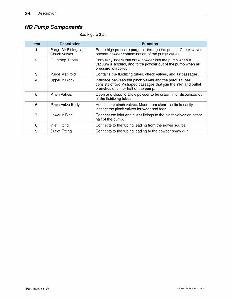
HD Pump Components See Figure 2-2.
Item Description Function
1 Purge Air Fittings andCheck Valves
Route high pressure purge air through the pump. Check valvesprevent powder contamination of the purge valves.
2 Fluidizing Tubes Porous cylinders that draw powder into the pump when avacuum is applied, and force powder out of the pump when airpressure is applied.
3 Purge Manifold Contains the fluidizing tubes, check valves, and air passages.
4 Upper Y Block Interface between the pinch valves and the porous tubes;consists of two Y-shaped passages that join the inlet and outletbranches of either half of the pump.
5 Pinch Valves Open and close to allow powder to be drawn in or dispensed outof the fluidizing tubes.
6 Pinch Valve Body Houses the pinch valves. Made from clear plastic to easilyinspect the pinch valves for wear and tear.
7 Lower Y Block Connect the inlet and outlet fittings to the pinch valves on eitherhalf of the pump.
8 Inlet Fitting Connects to the tubing leading from the power source
9 Outlet Fitting Connects to the tubing leading to the powder spray gun
Description 2-7
Part 1606783−06� 2019 Nordson Corporation
1
5
3
9
4
8
2
7
6
Encore HD Pump
1
2
3
4
7
9
Encore HD+, XD Pump
5
6
8
Figure 2-2 Encore Pump Components
Description2-8
Part 1606783−06 � 2019 Nordson Corporation
Theory of Operation
Pumping The Encore HD pump consists of two halves that function identically. Thehalves alternately draw powder in and dispense powder out of the pump;while one half is drawing powder in, the other half is dispensing powder out.
Left Half Drawing Powder In
See Figure 2-3 View A.
The left suction pinch valve is open, while the left delivery pinch valve isclosed. Negative air pressure is applied to the left porous fluidizing tube,which draws powder in the inlet fitting, up the left side of the inletmanifold wear block, through the left suction pinch valve, and into the leftfluidizing tube.
After the negative air pressure has been on for the specified time, thefluidizing tube’s negative air pressure shuts off and the left suction pinchvalve closes.
Right Half Dispensing Powder Out
See Figure 2-3 View B.
The right suction pinch valve is closed, while the right delivery pinchvalve is open. Positive air pressure is applied to the right porousfluidizing tube, which dispenses the powder out of the fluidizing tube,down the right delivery pinch valve, down the right side of the outletmanifold wear block, out the delivery fitting, and out to the tubing thatleads to the powder spray gun.
As the sides complete these processes, they alternate. In the exampleexplained above, the left half would now dispense powder out while the righthalf would draw powder in.
As each half dispenses powder out, the powder in the tubing blendstogether, resulting in a consistent flow of powder from the spray gun.
Description 2-9
Part 1606783−06� 2019 Nordson Corporation
View A View B
Left Side Drawing InRight Side Dispensing
Left Side DispensingRight Side Drawing In
L R
R
L
Left halfsuctionvalveopen
Right halfdeliveryvalveopen
Air
PowderOut
PowderIn
Air
PowderOut
PowderIn
L
R
RL
Right halfsuctionvalveopen
Left halfdeliveryvalveopen
Figure 2-3 Operation of Pump (Shown as rear, right view of the pump)
Description2-10
Part 1606783−06 � 2019 Nordson Corporation
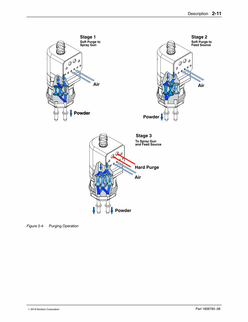
Purging See Figure 2-4. When the operator initiates a color change, the pump goesthrough a three-stage purge process.
Stage 1:Soft Purge to Spray Gun
The suction pinch valves close, while the delivery pinch valves remain open.Pump assist air pressure turns on, starting at a low pressure and building upto maximum pump assist pressure. The air dispenses powder out of bothfluidizing tubes, through the powder delivery tubing and spray gun and outinto the booth.
Stage 2: Soft Purge to Feed Source
The suction pinch valves are open, while the delivery pinch valves close.Pump assist air pressure turns on, starting at a low pressure and building upto maximum pump assist pressure. The air dispenses powder out of bothfluidizing tubes, through the powder suction tubing, and back into thepowder feed source.
Stage 3: Hard Purge to Spray Gun and Feed Source
The delivery pinch valves open. Pump assist air pressure turns on atmaximum pressure, while pulses of line air pressure are sent down thepurge air fittings at the tops of the fluidizing tubes. The pulses of air removeany powder that remains in the pump, spray gun, and suction and deliverytubing.
After the delivery side is purged, the delivery pinch valves close and thesuction pinch valves open. The suction side is purged in the same way asthe delivery side.
Description 2-11
Part 1606783−06� 2019 Nordson Corporation
Air
Powder
Stage 1Soft Purge to
PowderPowder
Stage 2Soft Purge toFeed SourceSpray Gun
Air
Powder
Stage 3To Spray Gunand Feed Source
Air
Hard Purge
Figure 2-4 Purging Operation
Description2-12
Part 1606783−06 � 2019 Nordson Corporation
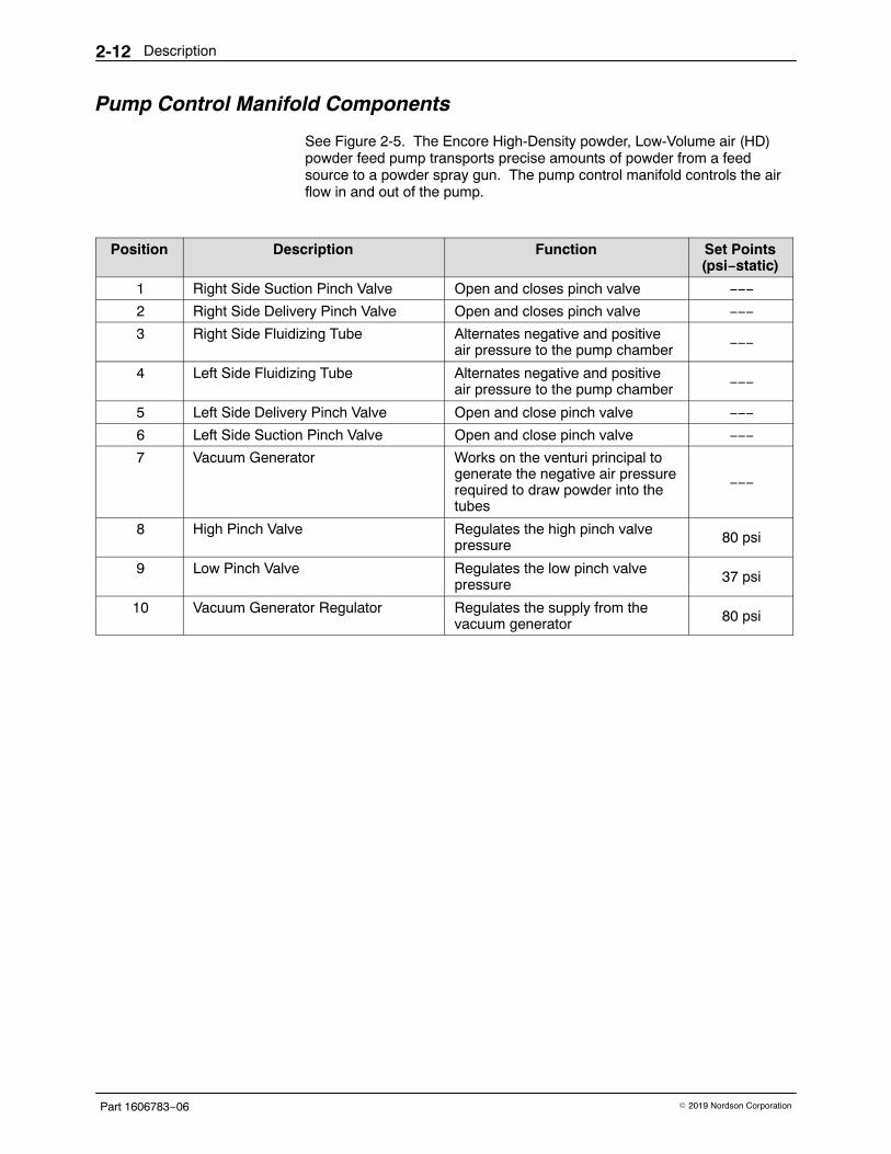
Pump Control Manifold Components
See Figure 2-5. The Encore High-Density powder, Low-Volume air (HD)powder feed pump transports precise amounts of powder from a feedsource to a powder spray gun. The pump control manifold controls the airflow in and out of the pump.
Position Description Function Set Points(psi−static)
1 Right Side Suction Pinch Valve Open and closes pinch valve −−−
2 Right Side Delivery Pinch Valve Open and closes pinch valve −−−
3 Right Side Fluidizing Tube Alternates negative and positiveair pressure to the pump chamber −−−
4 Left Side Fluidizing Tube Alternates negative and positiveair pressure to the pump chamber −−−
5 Left Side Delivery Pinch Valve Open and close pinch valve −−−
6 Left Side Suction Pinch Valve Open and close pinch valve −−−
7 Vacuum Generator Works on the venturi principal togenerate the negative air pressurerequired to draw powder into thetubes
−−−
8 High Pinch Valve Regulates the high pinch valvepressure 80 psi
10 Vacuum Generator Regulator Regulates the supply from thevacuum generator 80 psi
Description 2-13
Part 1606783−06� 2019 Nordson Corporation
5
21
7
10
4
3
6
9
8
Figure 2-5 Pump Control Manifold
Description2-14
Part 1606783−06 � 2019 Nordson Corporation
Installation 3-1
Part 1606783−06� 2019 Nordson Corporation
Section 3Installation
WARNING: Allow only qualified personnel to perform the following tasks.Follow the safety instructions in this document and all other relateddocumentation.
Wall/Rail Mount Systems
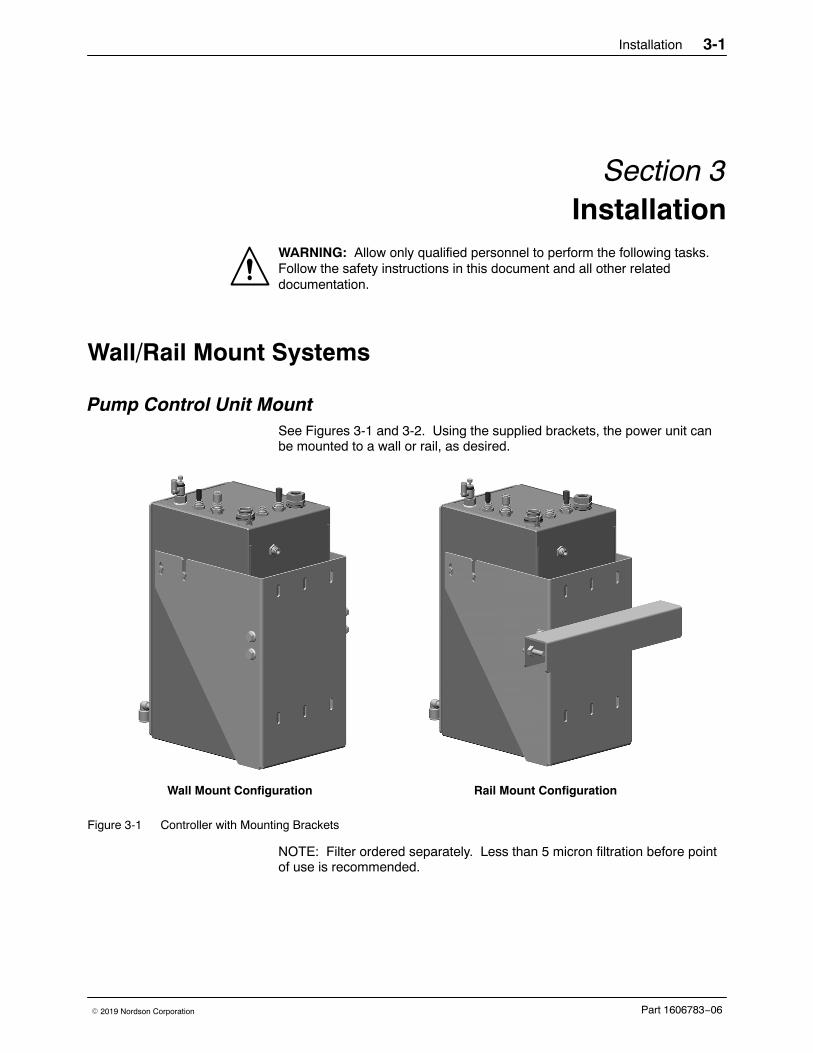
Pump Control Unit Mount See Figures 3-1 and 3-2. Using the supplied brackets, the power unit canbe mounted to a wall or rail, as desired.
Wall Mount Configuration Rail Mount Configuration
Figure 3-1 Controller with Mounting Brackets
NOTE: Filter ordered separately. Less than 5 micron filtration before pointof use is recommended.
Installation3-2
Part 1606783−06 � 2019 Nordson Corporation
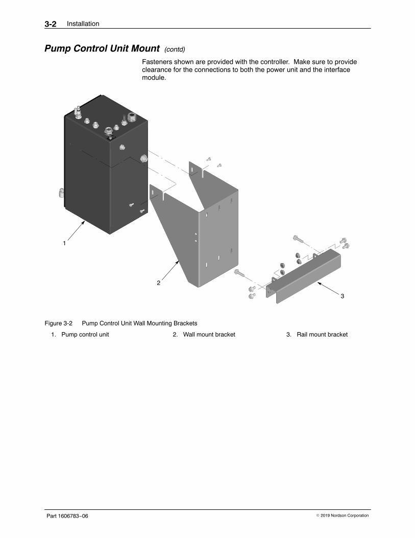
Pump Control Unit Mount (contd)
Fasteners shown are provided with the controller. Make sure to provideclearance for the connections to both the power unit and the interfacemodule.
1
2
3
Figure 3-2 Pump Control Unit Wall Mounting Brackets
1. Pump control unit 2. Wall mount bracket 3. Rail mount bracket
Installation 3-3
Part 1606783−06� 2019 Nordson Corporation
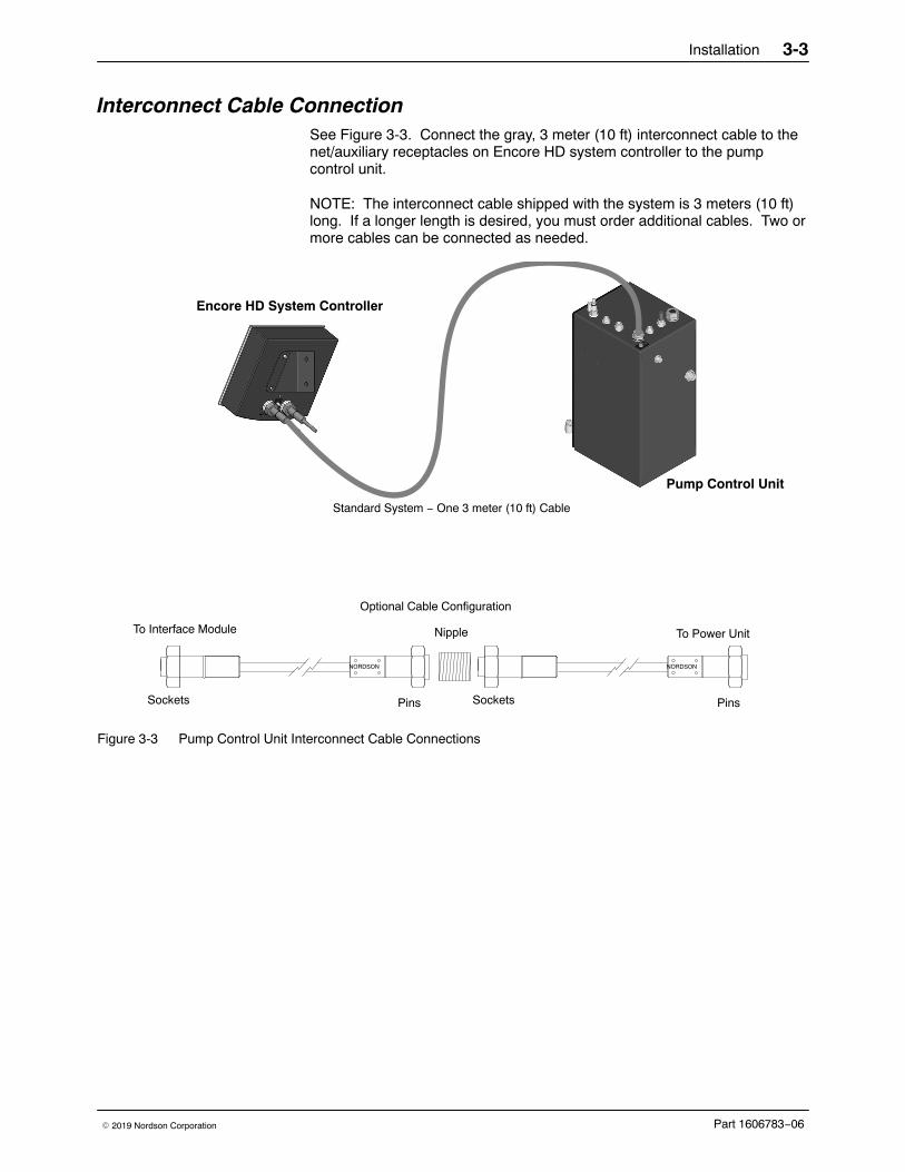
Interconnect Cable Connection See Figure 3-3. Connect the gray, 3 meter (10 ft) interconnect cable to thenet/auxiliary receptacles on Encore HD system controller to the pumpcontrol unit.
NOTE: The interconnect cable shipped with the system is 3 meters (10 ft)long. If a longer length is desired, you must order additional cables. Two ormore cables can be connected as needed.
NORDSON
PinsSockets
NORDSON
SocketsPins
Nipple To Power UnitTo Interface Module
Standard System − One 3 meter (10 ft) Cable
Optional Cable Configuration
Encore HD System Controller
Pump Control Unit
Figure 3-3 Pump Control Unit Interconnect Cable Connections
Installation3-4
Part 1606783−06 � 2019 Nordson Corporation
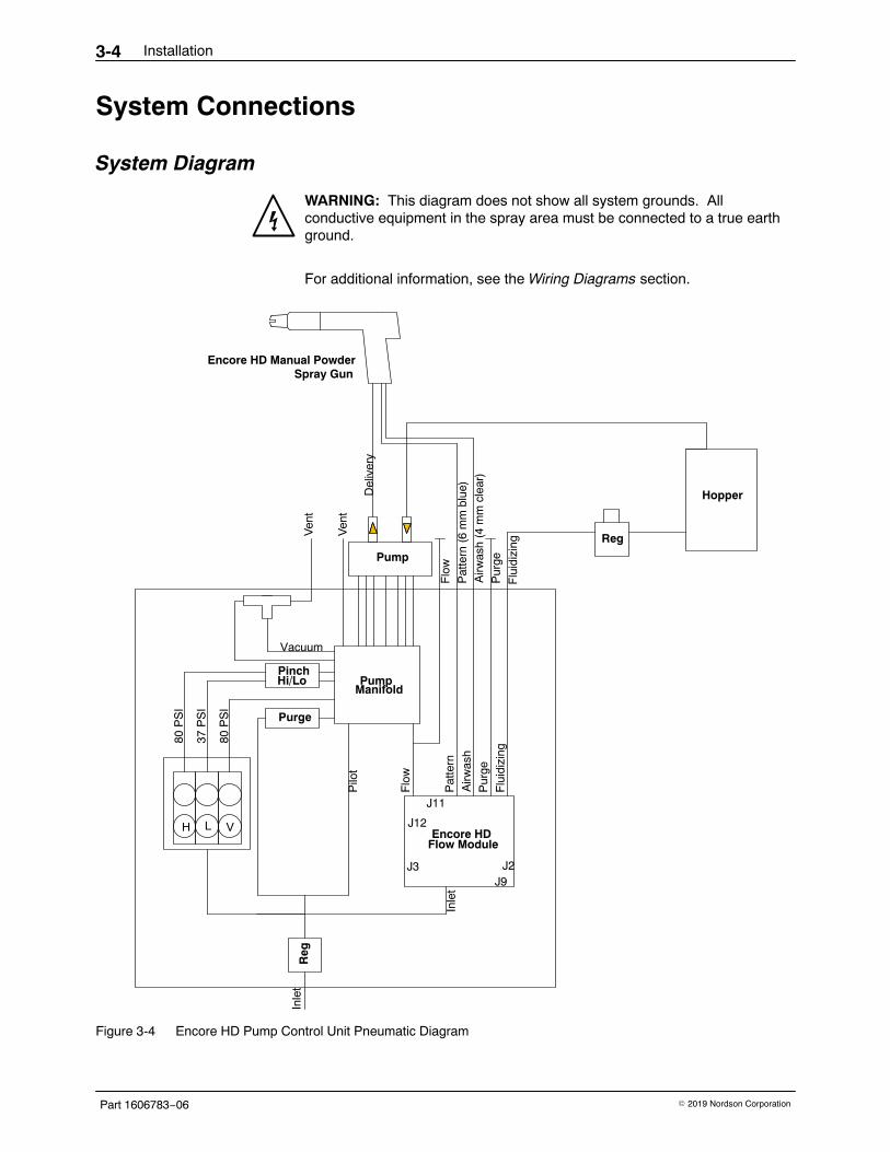
System Connections
System Diagram
WARNING: This diagram does not show all system grounds. Allconductive equipment in the spray area must be connected to a true earthground.
For additional information, see the Wiring Diagrams section.
Encore HD
J11
J12
J2J3J9
Flu
idiz
ing
Pur
ge
Airw
ash
Pat
tern
Flo
w
Inle
t
PumpManifold
Reg
Purge
PinchHi/Lo
Vacuum
Pump
Flu
idiz
ing
Pur
ge
Airw
ash
(4 m
m c
lear
)
Pat
tern
(6
mm
blu
e)
Flo
w
80 P
SI
37 P
SI
80 P
SI
Ven
t
Ven
t
Reg
Hopper
Pilo
t
Inle
t
Del
iver
y
Flow ModuleH L V
Encore HD Manual PowderSpray Gun
Figure 3-4 Encore HD Pump Control Unit Pneumatic Diagram
Installation 3-5
Part 1606783−06� 2019 Nordson Corporation
Power SupplyRelay/Fuses
VBF Motor
Encore HD Flow Module
PumpManifold
Blue LED
Pinch Hi/Low Valve
Pump Purge Valve
AC Power
Filter
6 54 3
2 17
98
10
J11
J12
J2J3
J9
J1
VBF
NET
Encore HDEncore HD Manual PowderSystem ControllerSpray Gun
Figure 3-5 Encore HD Pump Control Unit Electrical Diagram
Installation3-6
Part 1606783−06 � 2019 Nordson Corporation
Pump Control Unit Connections The Encore HD spray gun is controlled by the system controller and pumpcontrol unit connected by a network/power cable.
The pump control unit houses a 24Vdc power supply, circuit board, andiFlow� air controller and valves used to control the Encore HD pump.
The system controller houses the controller interface panel, which containsthe displays and controls used to set and adjust electrostatic and flowsettings delivered to the spray gun.
Electrode Air Wash
Pump Control UnitTop View
System ControllerBottom View
Pump Control ViewFront View
Needle Valve
ElectrodeAir Wash(4 mm)
Purge Air (Not Used in HD Systems)
Pattern Air (6 mm)
Net orAuxiliary
Vibrator MotorPower Cord
Ground(To Dolly)
Fluidizing Air Check Valve(8 mm to 6 mm)
Flow Air (8 mm)
Ground
Network/Power
Spray Gun Cable
Interconnect Cable
(To Gun)
Power Cord(15 ft.)
L1
L1
L1
(Brown)
(Blue)
(Green/Yellow)
Figure 3-6 Encore HD System Controller Connections
Installation 3-7
Part 1606783−06� 2019 Nordson Corporation
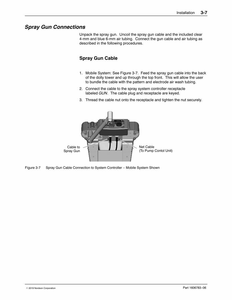
Spray Gun Connections Unpack the spray gun. Uncoil the spray gun cable and the included clear4-mm and blue 6-mm air tubing. Connect the gun cable and air tubing asdescribed in the following procedures.
Spray Gun Cable
1. Mobile System: See Figure 3-7. Feed the spray gun cable into the backof the dolly tower and up through the top front. This will allow the userto bundle the cable with the pattern and electrode air wash tubing.
2. Connect the cable to the spray system controller receptaclelabeled GUN. The cable plug and receptacle are keyed.
3. Thread the cable nut onto the receptacle and tighten the nut securely.
Net Cable(To Pump Contol Unit)
Cable toSpray Gun
Figure 3-7 Spray Gun Cable Connection to System Controller − Mobile System Shown
Installation3-8
Part 1606783−06 � 2019 Nordson Corporation
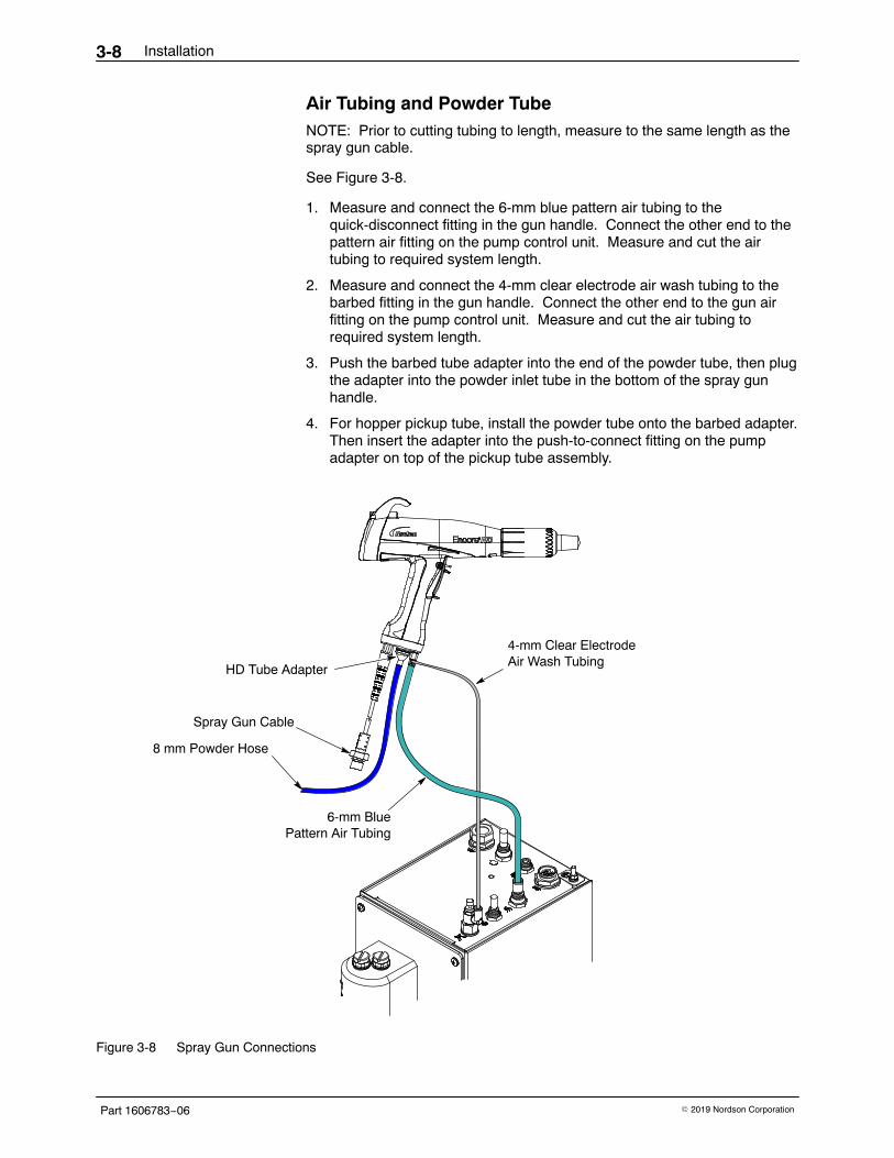
Air Tubing and Powder Tube NOTE: Prior to cutting tubing to length, measure to the same length as thespray gun cable.
See Figure 3-8.
1. Measure and connect the 6-mm blue pattern air tubing to thequick-disconnect fitting in the gun handle. Connect the other end to thepattern air fitting on the pump control unit. Measure and cut the airtubing to required system length.
2. Measure and connect the 4-mm clear electrode air wash tubing to thebarbed fitting in the gun handle. Connect the other end to the gun airfitting on the pump control unit. Measure and cut the air tubing torequired system length.
3. Push the barbed tube adapter into the end of the powder tube, then plugthe adapter into the powder inlet tube in the bottom of the spray gunhandle.
4. For hopper pickup tube, install the powder tube onto the barbed adapter.Then insert the adapter into the push-to-connect fitting on the pumpadapter on top of the pickup tube assembly.
4-mm Clear ElectrodeAir Wash Tubing
HD Tube Adapter
Spray Gun Cable
8 mm Powder Hose
6-mm BluePattern Air Tubing
Figure 3-8 Spray Gun Connections
Installation 3-9
Part 1606783−06� 2019 Nordson Corporation
Bundling Tubing and Cable See Figure 3-9. Use the sections of black spiral wrap supplied with thesystem to bundle together the spray gun cable, air tubing, and powder hose.
AdjustableCable Ties
BlackSpiral Wrap
Figure 3-9 Bundling Tubing (Shown with Mobile System)
NOTE: See Figure 3-9. The minimum powder hose length is 60 ft. For the Mobile Systems: The tubing is coiled under the dolly platform fromthe factory. If additional distance from dolly is required, open the tubeholders and uncoil to the required length. Close the tube holders, beingcareful not to over tighten.
Spiral wrap is used to protect the tubing from the swivel castors.
For Standalone and Rail/Wall systems: The tubing must be coiled in a 3 ftdiameter in a horizontal orientation.
Installation3-10
Part 1606783−06 � 2019 Nordson Corporation
Main System Air and Electrical Connections
Main System Air Supply See Figure 3-10. The air supply pressure should be6.0−7.6 bar (87−110 psi).
For rail/wall mount systems, an optional input air kit with connectors,couplings, and 20 ft of 10 mm tubing is available. Refer to the Parts sectionfor the kit contents and ordering information.
NOTE: Compressed air should be supplied from an air drop equipped witha self-relieving shutoff valve. The air must be clean and dry. A refrigerantor desiccant-type air drier and air filters are recommended.
10-mm Air TubingOutput to Pump Control Unit
Air Filter
10-mm Air TubingMain Supply Air Input
Figure 3-10 System Air Supply Connection (Shown with Mobile System)
Installation 3-11
Part 1606783−06� 2019 Nordson Corporation
Standalone, Rail Mount, and Wall Mount System AirSupply See Figure 3-11.
1. Note the orientation of the flow indicator (5) on the top of the filter.
1
12
2
3
4
6
5
7
FROM MAIN SUPPLY
TO PUMPCONTROL
UNIT
AIR IN
AIR OUT
Figure 3-11 Air Filter Installation − Standalone and Rail/Wall Mount Systems
1. 10-mm air tubing (blue)2. 10-mm tube x 1/2 male connectors3. M5 screws
4. Bracket5. Flow indicator
6. Release latch7. Customer-supplied fasteners
Installation3-12
Part 1606783−06 � 2019 Nordson Corporation
Encore HD Powder Pump Hose See Figure 3-12
Standard 8-mm OD Poly Tubing 1. Cut the poly tubing with a tubing cutter. Powder cross-contamination
may result if the powder tubing is cut unevenly.
2. Install the poly tubing (3) into the lower Y block (1) and push to internalconnector fitting (not shown)
Flexible 8-mm OD Tubing 1. The barbed adapters used to connect flexible tubing to the pump are
shipped with the pump.
2. Install the end of the adapter (2) into the lower Y block (1). Push tointernal connect fitting.
3. Push the flexible powder tubing (4) over the barbed ending of theadapter (2).
1
3
1
2
4
Flexible TubingPoly Tubing
Figure 3-12 Encore HD Pump Tubing Installation
1. Lower Y block2. Barbed tubing adapter
3. Poly tubing4. Flexible tubing
Installation 3-13
Part 1606783−06� 2019 Nordson Corporation
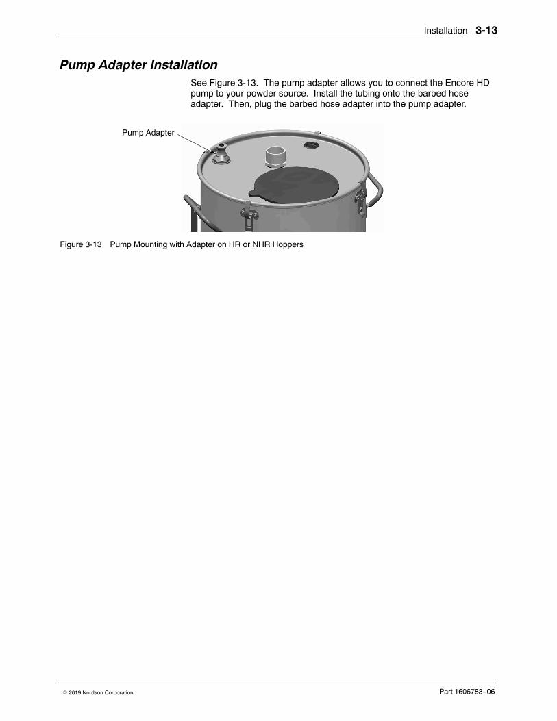
Pump Adapter Installation See Figure 3-13. The pump adapter allows you to connect the Encore HDpump to your powder source. Install the tubing onto the barbed hoseadapter. Then, plug the barbed hose adapter into the pump adapter.
Pump Adapter
Figure 3-13 Pump Mounting with Adapter on HR or NHR Hoppers
Installation3-14
Part 1606783−06 � 2019 Nordson Corporation
Electrical Connections
CAUTION: If you are setting up a vibratory box feeder system, check thesystem identification plate for the correct voltage. Connecting a system witha 115 Vac vibrator motor to 230 Vac could damage the vibrator motor.
NOTE: The spray gun controller is rated for 100−240 Vac at 50/60 Hz,single phase, and is marked as such, but the power supplied to the systemmust match the vibrator motor rating.
Wire the system power cord to a customer-supplied three-prong plug.Connect the plug to a receptacle that will supply the system with the correctvoltage.
Wire Color Function
Blue N (neutral)
Brown L (hot)
Green/Yellow GND (ground)
System Ground WARNING: All conductive system components in the spray area must beconnected to a true earth ground. Failure to observe this warning couldresult in an electrostatic discharge strong enough to cause a fire orexplosion.
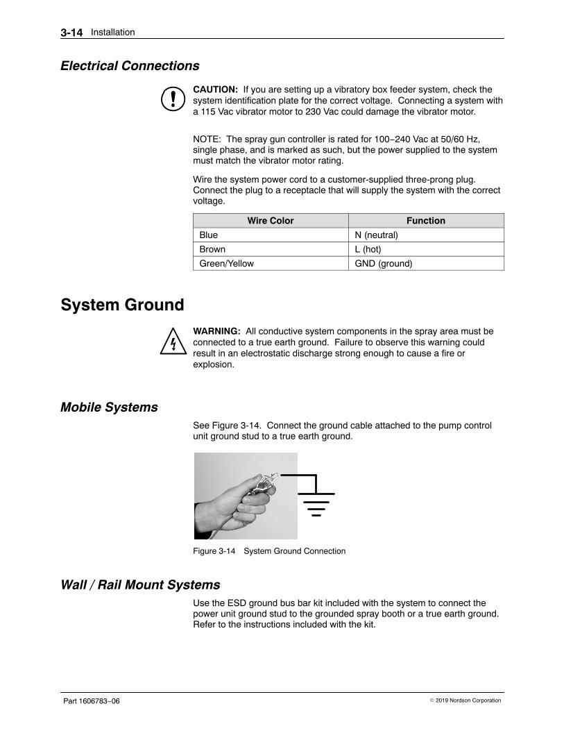
Mobile Systems See Figure 3-14. Connect the ground cable attached to the pump controlunit ground stud to a true earth ground.
Figure 3-14 System Ground Connection
Wall / Rail Mount Systems Use the ESD ground bus bar kit included with the system to connect thepower unit ground stud to the grounded spray booth or a true earth ground.Refer to the instructions included with the kit.
Operation 4-1
Part 1606783−06� 2019 Nordson Corporation
Section 4Operation
WARNING: Allow only qualified personnel to perform the following tasks.Follow the safety instructions in this document and all other relateddocumentation.
WARNING: This equipment can be dangerous unless it is used accordancewith the rules laid down in this manual.
WARNING: All electrically conductive equipment in the spray area must begrounded. Ungrounded or poorly grounded equipment can store anelectrostatic charge which can give personnel a severe shock or arc andcause a fire or explosion.
European Union, ATEX, Special Conditions for Safe Use1. The Encore HD manual applicator shall only be used with the associated
Encore HD system controller and Encore HD pump control unit, over theambient temperature range of +15 �C to +40 �C.
2. Equipment may only be used in areas of low impact risk.
3. Caution should be taken when cleaning plastic surfaces of theEncore HD controller and interface. There is a potential for staticelectricity build up on these components.
Operation4-2
Part 1606783−06 � 2019 Nordson Corporation
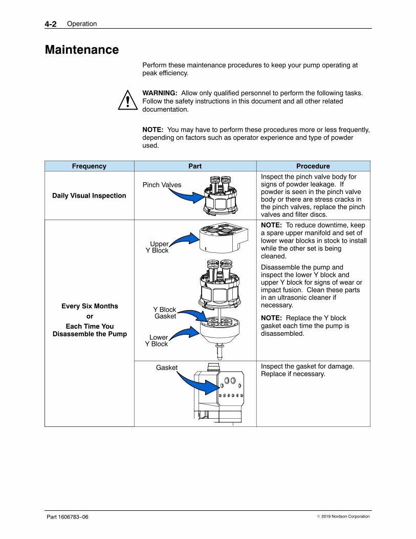
Maintenance Perform these maintenance procedures to keep your pump operating atpeak efficiency.
WARNING: Allow only qualified personnel to perform the following tasks.Follow the safety instructions in this document and all other relateddocumentation.
NOTE: You may have to perform these procedures more or less frequently,depending on factors such as operator experience and type of powderused.
Frequency Part Procedure
Daily Visual Inspection
Pinch ValvesInspect the pinch valve body forsigns of powder leakage. Ifpowder is seen in the pinch valvebody or there are stress cracks inthe pinch valves, replace the pinchvalves and filter discs.
Every Six Months
or
Each Time YouDisassemble the Pump
Y BlockGasket
UpperY Block
LowerY Block
NOTE: To reduce downtime, keepa spare upper manifold and set oflower wear blocks in stock to installwhile the other set is beingcleaned.
Disassemble the pump andinspect the lower Y block andupper Y block for signs of wear orimpact fusion. Clean these partsin an ultrasonic cleaner ifnecessary.
NOTE: Replace the Y blockgasket each time the pump isdisassembled.
Gasket Inspect the gasket for damage.Replace if necessary.
Troubleshooting 5-1
Part 1606783−06� 2019 Nordson Corporation
Section 5Troubleshooting
WARNING: Allow only qualified personnel to perform the following tasks.Follow the safety instructions in this document and all other relateddocumentation.
WARNING: Before making repairs to the controller or spray gun, shut offsystem power and disconnect the power cord. Shut off the compressed airsupply to the system and relieve the system pressure. Failure to observethis warning could result in personal injury.
These troubleshooting procedures cover only the most common problems.If you cannot solve a problem with the information given here, contactNordson technical support at (800) 433−9319 or your local Nordsonrepresentative for help.
Troubleshooting5-2
Part 1606783−06 � 2019 Nordson Corporation
Pump Troubleshooting
Problem Possible Cause Corrective Action
1. Reduced powder output(pinch valves areopening and closing)
Blockage in the powdertubing to the spray gun
Check the tubing for blockages. Purgethe pump and spray gun.
Defective pump air flowcontrol valve
Clean the pump air flow control valve.
Defective check valve Replace the check valves.
2. Reduced powder output(pinch valves are notopening and closing)
Defective pinch valve Replace the pinch valves and filterdiscs.
Defective pinch solenoidvalve
Replace the solenoid valve. Refer toeither the pump panel or controlmanifold manual for more information.
Defective check valve Replace the check valves.
3. Reduced powder input(loss of suction fromfeed source)
Blockage in the powdertubing from the feed source
Check the tubing for blockages. Purgethe pump and spray gun.
Loss of vacuum at thevacuum generator
Check the vacuum generator forcontamination.
Check the pump panel exhaust muffler.If the exhaust muffler appears to beplugged, replace it.
Defective pump air flowcontrol valve
Clean the pump air flow control valve.Refer to either the pump panel orcontrol manifold manual for moreinformation.
Troubleshooting 5-3
Part 1606783−06� 2019 Nordson Corporation
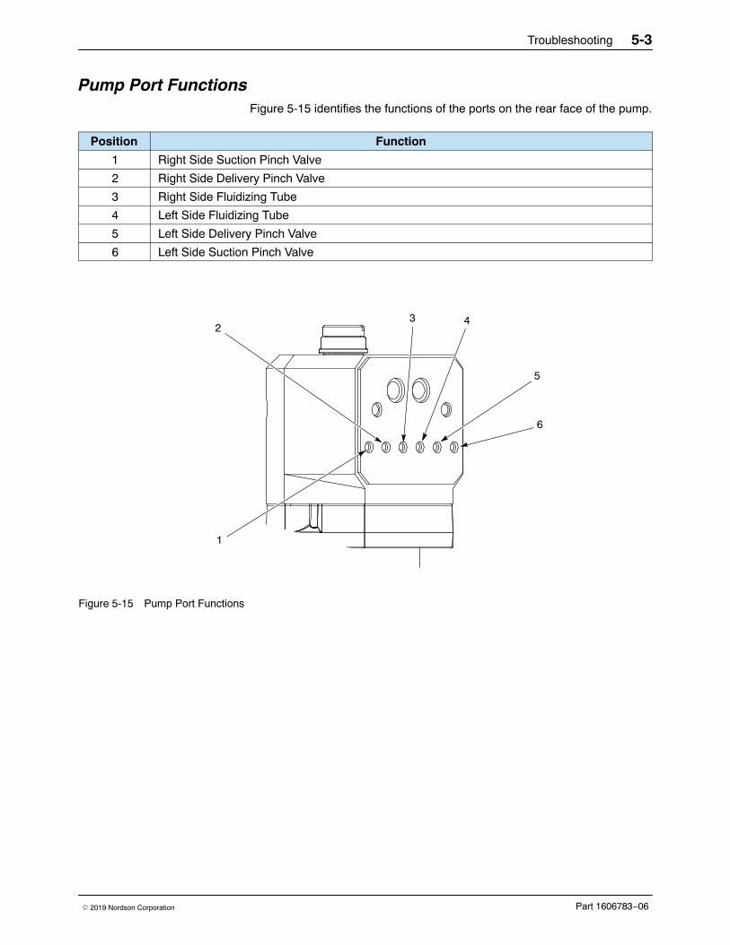
Pump Port Functions Figure 5-15 identifies the functions of the ports on the rear face of the pump.
Position Function
1 Right Side Suction Pinch Valve
2 Right Side Delivery Pinch Valve
3 Right Side Fluidizing Tube
4 Left Side Fluidizing Tube
5 Left Side Delivery Pinch Valve
6 Left Side Suction Pinch Valve
42
1
3
5
6
Figure 5-15 Pump Port Functions
Troubleshooting5-4
Part 1606783−06 � 2019 Nordson Corporation
Manifold Troubleshooting Problem Possible Cause Corrective Action
Check the tubing for blockages.Purge the pump and spray gun.
Defective pump air flow controlvalve
Clean the pump air flow control valve.Refer to iFlow Module Repair onpage 6-4 for instructions.
If the problem persists, replace thepump air flow control valve. Refer toiFlow Module Repair on page 6-4 forinstructions.
Defective pump check valve Replace the check valves.
2. Reduced powderoutput (pinch valvesare not opening andclosing)
Defective pinch valve Replace the pinch valves and filterdiscs.
Defective solenoid valve Replace the solenoid valve. Refer toSolenoid and Flow Control ValveFunctions on page 5-5 to determinewhich solenoid valve controls theaffected pinch valve.
Defective pump check valve Replace the check valves.
3. Reduced powderinput (loss of suctionfrom feed source)
Blockage in the powder tubingfrom the feed source
Check the tubing for blockages.Purge the pump and spray gun.
Loss of vacuum at the vacuumgenerator
Check the vacuum generator forcontamination.
Check the pump panel exhaustmuffler. If the exhaust mufflerappears to be plugged, replace it.
Defective pump air flow controlvalve
Clean the pump air flow control valve.Refer to iFlow Module Repair onpage 6-4 for instructions.
If the problem persists, replace thepump air flow control valve. Refer toiFlow Module Repair on page 6-4 forinstructions.
4. Spray gun fan patternchanges
Defective pattern air flow controlvalve
Clean the pattern air flow controlvalve. Refer to iFlow Module Repairon page 6-4 for instructions.
If the problem persists, replace thepattern air flow control valve. Refer toiFlow Module Repair on page 6-4 forinstructions.
Troubleshooting 5-5
Part 1606783−06� 2019 Nordson Corporation
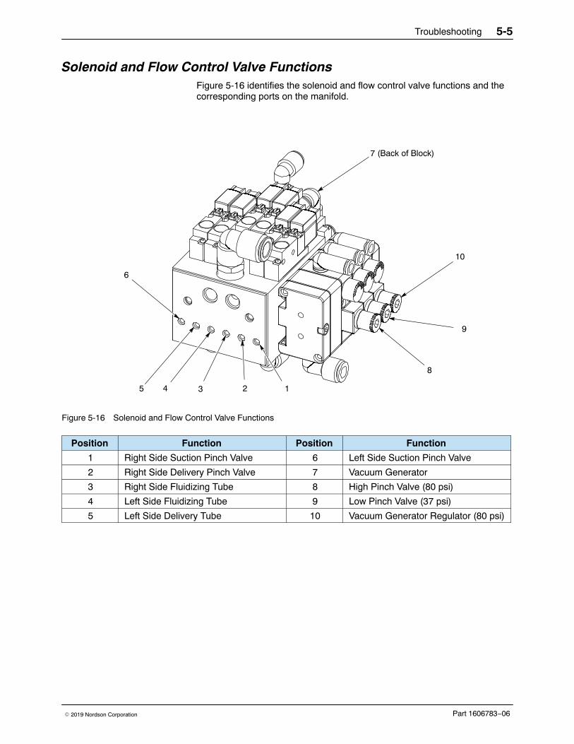
Solenoid and Flow Control Valve Functions Figure 5-16 identifies the solenoid and flow control valve functions and thecorresponding ports on the manifold.
6
12345
7 (Back of Block)
8
9
10
Figure 5-16 Solenoid and Flow Control Valve Functions
Position Function Position Function
1 Right Side Suction Pinch Valve 6 Left Side Suction Pinch Valve
2 Right Side Delivery Pinch Valve 7 Vacuum Generator
3 Right Side Fluidizing Tube 8 High Pinch Valve (80 psi)
4 Left Side Fluidizing Tube 9 Low Pinch Valve (37 psi)
5 Left Side Delivery Tube 10 Vacuum Generator Regulator (80 psi)
Troubleshooting5-6
Part 1606783−06 � 2019 Nordson Corporation
Re-Zero Procedure Perform this procedure if the system controller interface indicates air flowwhen the spray gun is not triggered on, or if a Flow Air or Atomizing Air FlowHigh Help code (H25 or H26) appears. See the system manual foradditional information on help codes.
Before performing a re-zero procedure:
� Make sure the air pressure being supplied to the system is higherthan the minimum 5.86 bar (85 psi).
� Make sure no air is leaking through the module output fittings orfrom around the solenoid valves or proportional valves.Re-zeroing modules with leaks will result in additional errors.
1. At the pump control panel, disconnect the 6 mm pattern air tubing andinstall 8-mm plugs in the output fittings.
2. Press the Nordson button for 5 seconds to display the controllerfunctions. F00−00 is displayed.
3. Rotate the knob until F10−00 is displayed.
4. Press the Enter button, then rotate the knob to display F10−01.
5. Press the Enter button. The system controller will re-zero the flow andpattern air and reset the function display to F10−00.
6. Remove the plugs from the pattern air output fittings and reconnect theair tubing.
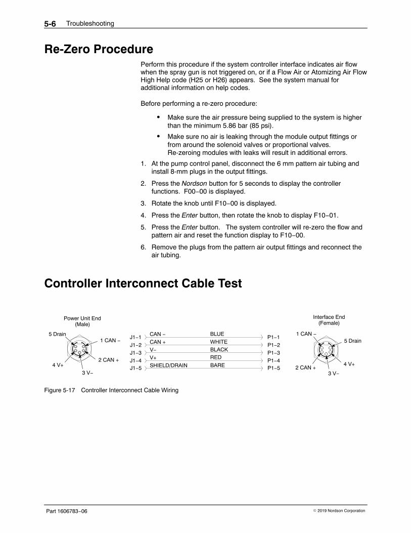
Controller Interconnect Cable Test
CAN −
CAN +
V−
V+
SHIELD/DRAIN
J1−1
J1−2
J1−3J1−4J1−5
BLUE
WHITEBLACKRED
BARE
5 Drain1 CAN −
2 CAN +
3 V−4 V+
P1−3
P1−5P1−4
P1−1
P1−25 Drain
4 V+
1 CAN −
2 CAN +3 V−
Power Unit End(Male)
Interface End(Female)
Figure 5-17 Controller Interconnect Cable Wiring
Repair 6-1
Part 1606783−06� 2019 Nordson Corporation
Section 6Repair
WARNING: Allow only qualified personnel to perform the following tasks.Follow the safety instructions in this document and all other relateddocumentation.
WARNING: Shut off the controller and disconnect the power cord ordisconnect and lock out power at a breaker or disconnect ahead of thecontroller before opening the controller enclosures. Failure to observe thiswarning could result in a severe electrical shock and personal injury.
CAUTION: Electrostatic sensitive device. To avoid damaging the controllercircuit boards, wear a grounding wrist strap and use proper groundingtechniques when making repairs.
Refer to the Wiring Diagram section for the pump control unit electricalschematic and harness connections.
Repair6-2
Part 1606783−06 � 2019 Nordson Corporation
Removing Panel Assembly 1. Disconnect the main power and air.
2. Remove the ten screws (2) securing the panel assembly (3) to theenclosure (1).
3. Slowly remove panel assembly
CAUTION: Handle cable and connectors with care. When reassembling,do not allow cables or air lines to become pinched or twisted at the back ofthe cabinet wall.
ExternalEnclosureGround
InternalEnclosure
Ground
1
3
2
Figure 6-18 Sub-Panel Removal
1. Enclosure2. Screws
3. Panel Assembly
Repair 6-3
Part 1606783−06� 2019 Nordson Corporation
Sub-Panel Components Refer to the following when making repairs:
� Parts section for parts and service kits.
� Wiring Diagrams for wiring diagrams and circuit board connections.
� Regulator Adjustment and iFlow Module Repair for repair procedures.
Regulator Adjustment See Figure 6-19.
Use the iFlow Air Verification Kit and this procedure to adjust the regulatorthat supplies air to the iFlow module after replacing.
NOTE: The plugs and connectors in the regulator ports are not suppliedwith a replacement regulator. Re-use the plugs and connectors from the oldregulator in the replacement regulator.
1. Unplug one of the fittings from the regulator and plug the gauge into thefitting.
2. Set the regulator to 85 psi.
3. Remove the gauge and replace the plug in the regulator fitting.
4. Push the regulator knob to lock the setting.
10014746
Fittings
Figure 6-19 Regulator Adjustment
Repair6-4
Part 1606783−06 � 2019 Nordson Corporation
iFlow Module Repair The iFlow module consists of a circuit board and air manifold, on which aremounted two proportional valves, transducers, and four solenoid valves.Repair of the flow module is limited to cleaning or replacing the proportionalvalves, and replacing the solenoid valves, check valves, and fittings.
CAUTION: The module circuit board is an electrostatic sensitivedevice (ESD). To prevent damage to the board when handling it, wear agrounding wrist strap connected to ground. Handle the board only by itsedges.
Testing iFlow Modules
CAUTION: Handle the orifice assembly with care. Rough handling candamage the orifice and affect the manometer reading.
Conveyance Air Flow
NOTE: Perform a color change and verify that all powder is removed fromthe pump before starting this procedure.
1. Use the flow verification tool (1039881) and connect to the delivery portof the pump with 10 ft of 8 mm tubing.
2. Set the delivery to 100% and set assist air to 00% and trigger the pumpON. The monometer should read 4.0−5.0 psi (0.2−0.3 bar).
3. Increase the assist air to +50% and trigger the pump ON. Themonometer should read 7.0−8.0 psi (0.5−0.6 bar).
4. Decrease the assist air to −50% and trigger the pump ON. Themonometer should read 1.0−3.0 psi (0.1−0.2 bar).
Pattern Air
Use the flow verification tool (1039881) with its instructions and connect tothe pattern air output.
Repair 6-5
Part 1606783−06� 2019 Nordson Corporation
Solenoid Valve Replacement See Figure 6-20. To remove the solenoid valves (13), remove the twoscrews in the valve body and lift the valve off the manifold.
Make sure the O-rings furnished with the new valves are in place beforeinstalling the new valve on the manifold.
Proportional Valve Cleaning See Figure 6-20. A dirty air supply can cause the proportional valve (6) tomalfunction. Follow these instructions to disassemble and clean the valve.
1. Disconnect the coil (3) wiring from the circuit board (1). Remove thenut (2) and coil from the proportional valve (6).
2. Remove the two long screws (4) and two short screws (5) to remove theproportional valve from the manifold.
CAUTION: The valve parts are very small; be careful not to lose any. Donot mix the springs from one valve with those from another. The valves arecalibrated for different springs.
3. Remove the valve stem (8) from the valve body (11).
4. Remove the valve cartridge (10) and spring (9) from the stem.
5. Clean the cartridge seat and seals, and the orifice in the valve body.Use low-pressure compressed air. Do not use sharp metal tools toclean the cartridge or valve body.
6. Install the spring and then the cartridge in the stem, with the plastic seaton the end of the cartridge facing out.
7. Make sure the O-rings furnished with the valve are in place on thebottom of the valve body.
8. Secure the valve body to the manifold with the long screws, making surethe arrow on the side of the body points toward the outlet fittings.
9. Install the coil over the valve stem, with the coil wiring pointing towardthe circuit board. Secure the coil with the nut and connect the coil wiringto the circuit board.
Proportional Valve Replacement See Figure 6-20. If cleaning the proportional valve does not correct the flowproblem then replace the valve. Before installing a new valve, remove theprotective cover from the bottom of the valve body. Be careful to not losethe O-rings under the cover.
Repair6-6
Part 1606783−06 � 2019 Nordson Corporation
2
3
4
6
5
71
Valve Body − Bottom Valve Body − Top
32
8
9
10
11
4
5
12
13
Proportional Valve Cleaning
Figure 6-20 iFlow Module Repair − Solenoid Valve Replacement and Proportional Valve Cleaning or Replacement
1. Circuit board2. Nut−coil to proportional valve (2)3. Coil−proportional valve (2)4. Long screws−valve to manifold (2)5. Short screws−valve stem to body (2)
6. Proportional valve (2)7. Direction of flow arrow8. Stem9. Spring
Vibrator Motor Replacement When replacing the vibrator motor, make sure you order the correct motorfor your voltage. Check the ID plate on the power unit. Replacementmotors include the power cable.
Refer to the Power Unit Wiring Diagram in the Troubleshooting section ofthis manual for internal VBF wiring.
Repair6-8
Part 1606783−06 � 2019 Nordson Corporation
Fluidizing Tube Replacement
WARNING: Shut off and relieve system air pressure before performing thefollowing tasks. Failure to relieve air pressure may result in personal injury.
1. Perform a color change to remove old powder from the pump, then relievethe system air pressure and disconnect the purge air tubing.
Retrofit Pump Standard Pump
Figure 6-21 Removing the purge air tubing.
2. Loosen the fluidizing tube access plug and pull the fluidizing tube straightout of the pump body.
Standard PumpRetrofit Pump
Figure 6-22 Loosening the fluidizing tubes
Repair 6-9
Part 1606783−06� 2019 Nordson Corporation
3. Pull the old fluidizing tube off the access plug, then seat the new fluidizingtube against the red o−ring.
Figure 6-23 Replacing the Access Plugs to the Fluidizing Tubes.
4. Install the fluidizing tube assemblies into the pump body. Tighten the accessplugs, then reconnect the purge air tubing.
Retrofit Pump Standard Pump
Figure 6-24 Reinstalling the Purge Air Tubing.
Repair6-10
Part 1606783−06 � 2019 Nordson Corporation
Pump Disassembly To reduce downtime, keep a spare pump in stock to replace a pump that isbeing repaired. Refer to Parts section for ordering information.
WARNING: Shut off and relieve system air pressure before performing thefollowing tasks. Failure to relieve air pressure may result in personal injury.
NOTE: Tag all air and powder tubing before disconnecting from the pump.
1. See Figure 6-25. Disconnect the purge air lines (1) from the top of thepump.
2. Disconnect the inlet and outlet powder tubing (2) from the bottom of thepump.
3. Remove the two screws, lock washers, and flat washers (3) securing thepump to the pump panel and move the pump to a clean work surface.
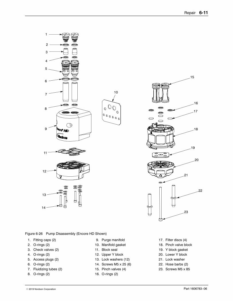
4. See Figure 6-26. Starting with the fluidizing tubes, disassemble thepump as shown. Gaskets that are glued on do not need to be removedunless they are damaged. Discard the Y block gasket (19).
NOTE: Refer to Pinch Valve Replacement on page 6-15 for instructions onremoving the pinch valves from the pinch valve body.
17. Filter discs (4)18. Pinch valve block19. Y block gasket20. Lower Y block21. Lock washer22. Hose barbs (2)23. Screws M5 x 85
Repair6-12
Part 1606783−06 � 2019 Nordson Corporation
Pump Assembly
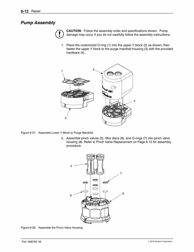
CAUTION: Follow the assembly order and specifications shown. Pumpdamage may occur if you do not carefully follow the assembly instructions.
1. Place the customized O-ring (1) into the upper Y block (2) as shown, thenfasten the upper Y block to the purge manifold housing (3) with the providedhardware (4).
1
2
3
4
Figure 6-27 Assemble Lower Y Block to Purge Manifold
2. Assemble pinch valves (5), filter discs (6), and O-rings (7) into pinch valvehousing (8). Refer to Pinch Valve Replacement on Page 6-15 for assemblyprocedure.
5
7
68
Figure 6-28 Assemble the Pinch Valve Housing
Repair 6-13
Part 1606783−06� 2019 Nordson Corporation
3. Install a new Y block gasket (10) over lower Y block (11), then thread longscrew and lock washer (12) through the lower Y block and into the pinchvalve housing, upper Y block and purge manifold. Hand tighten the screw.
9
12
10
11
Figure 6-29 Assemble Gasket and Lower Y Block
4. Assemble the check valves (15) O-rings (14) access plugs (16), and fittingcaps (13) together before replacing the fluidizing tubes (18). Then, once thatis complete, assemble the complete access plugs (17) and additionalO-rings onto the fluidizing tubes (18)
13
17
14
14
15
18
16
Figure 6-30 Assemble Fittings to Fluidizing Tubes
5. After the pump is assembled, completely tighten the long screw to fit allcomponents together securely.
Repair6-14
Part 1606783−06 � 2019 Nordson Corporation
6. Insert the assembled fluidizing tube (19) into the top of the purge manifold(20). Snug fit tubes to manifold.
20
19
Figure 6-31 Fasten Fluidizing Tubes into Manifold
7. Mount the pump to the cabinet before assembling the feed tubing to theports in the bottom of the pump. Refer to Installation on page 3-12 for moreinformation.
PolyTubingFlex Tubing
Figure 6-32 Assemble Tubing into Lower Y Block
Repair 6-15
Part 1606783−06� 2019 Nordson Corporation
Pinch Valve Replacement
CAUTION: Before placing the pinch valve body in a vise, pad the jaws.Tighten the vise only enough to hold the valve body firmly. Failure toobserve may result in damage to the pinch valve body.
Figure 6-33 shows the top of a pinch valve body.
� The top of the pinch valve body has the word “UP” molded on surface.
� The top side of the valve body has four air passages sealed with filter discsand o-rings.
NOTE: Always replace the Y block gasket and the filter discs included inthe pinch valve kit when replacing the pinch valves.
“UP” moldedon valve body
O−Rings &Filter Discs
Points onvalves pointto center ofchamber.
Figure 6-33 Top of Pinch Valve Body
Pinch Valve Removal1. Place the pinch valve body in a padded vise.
2. Grasp the bottom flange of a pinch valve with one hand and pull it awayfrom the pinch valve body.
3. Cut the flange off with scissors, then pull the rest of the pinch valve out ofthe top of the pinch valve body.
Figure 6-34 Pinch Valve Removal
Repair6-16
Part 1606783−06 � 2019 Nordson Corporation
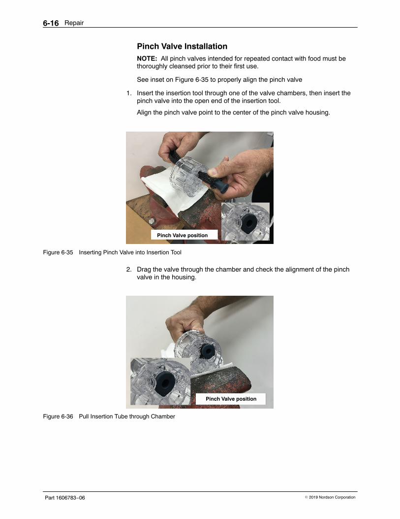
Pinch Valve Installation NOTE: All pinch valves intended for repeated contact with food must bethoroughly cleansed prior to their first use.
See inset on Figure 6-35 to properly align the pinch valve
1. Insert the insertion tool through one of the valve chambers, then insert thepinch valve into the open end of the insertion tool.
Align the pinch valve point to the center of the pinch valve housing.
Pinch Valve position
Figure 6-35 Inserting Pinch Valve into Insertion Tool
2. Drag the valve through the chamber and check the alignment of the pinchvalve in the housing.
Pinch Valve position
Figure 6-36 Pull Insertion Tube through Chamber
Repair 6-17
Part 1606783−06� 2019 Nordson Corporation
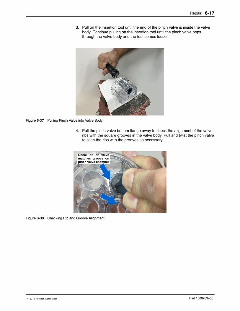
3. Pull on the insertion tool until the end of the pinch valve is inside the valvebody. Continue pulling on the insertion tool until the pinch valve popsthrough the valve body and the tool comes loose.
Figure 6-37 Pulling Pinch Valve into Valve Body
4. Pull the pinch valve bottom flange away to check the alignment of the valveribs with the square grooves in the valve body. Pull and twist the pinch valveto align the ribs with the grooves as necessary.
Check rib on valvematches groove onpinch valve chamber
Figure 6-38 Checking Rib and Groove Alignment
Repair6-18
Part 1606783−06 � 2019 Nordson Corporation
Your notes
Parts 7-1
Part 1606783−06� 2019 Nordson Corporation
Section 7Parts
Introduction To order parts, call the Nordson Industrial Coating Systems CustomerSupport Center at (800) 433-9319 or contact your local Nordsonrepresentative.
Using the Illustrated Parts List Numbers in the Item column correspond to numbers that identify parts inillustrations following each parts list. The code NS (not shown) indicatesthat a listed part is not illustrated. A dash (—) is used when the part numberapplies to all parts in the illustration.
The number in the Part column is the Nordson Corporation part number. Aseries of dashes in this column (- - - - - -) means the part cannot be orderedseparately.
The Description column gives the part name, as well as its dimensions andother characteristics when appropriate. Indentions show the relationshipsbetween assemblies, subassemblies, and parts.
� If you order the assembly, items 1 and 2 will be included.
� If you order item 1, item 2 will be included.
� If you order item 2, you will receive item 2 only.
The number in the Quantity column is the quantity required per unit,assembly, or subassembly. The code AR (As Required) is used if the partnumber is a bulk item ordered in quantities or if the quantity per assemblydepends on the product version or model.
Letters in the Note column refer to notes at the end of each parts list. Notescontain important information about usage and ordering. Special attentionshould be given to notes.
Item Part Description Quantity Note— 0000000 Assembly 11 000000 � Subassembly 2 A2 000000 � � Part 1
Parts7-2
Part 1606783−06 � 2019 Nordson Corporation
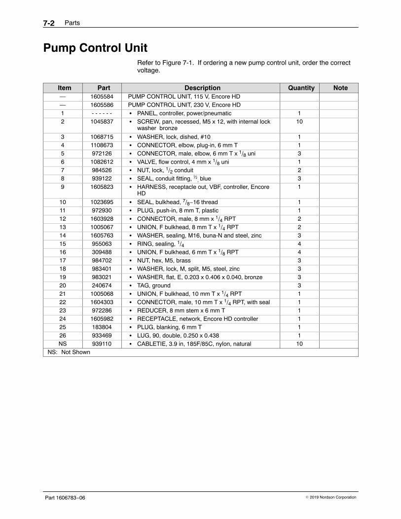
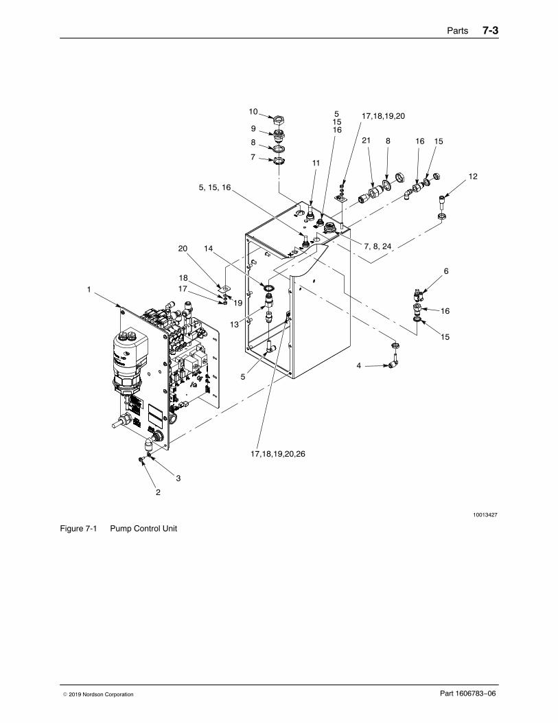
Pump Control Unit Refer to Figure 7-1. If ordering a new pump control unit, order the correctvoltage.
Item Part Description Quantity Note— 1605584 PUMP CONTROL UNIT, 115 V, Encore HD— 1605586 PUMP CONTROL UNIT, 230 V, Encore HD1 - - - - - - � PANEL, controller, power/pneumatic 12 1045837 � SCREW, pan, recessed, M5 x 12, with internal lock
washer bronze10
3 1068715 � WASHER, lock, dished, #10 14 1108673 � CONNECTOR, elbow, plug-in, 6 mm T 15 972126 � CONNECTOR, male, elbow, 6 mm T x 1/8 uni 36 1082612 � VALVE, flow control, 4 mm x 1/8 uni 17 984526 � NUT, lock, 1/2 conduit 28 939122 � SEAL, conduit fitting, ½, blue 39 1605823 � HARNESS, receptacle out, VBF, controller, Encore
HD1
10 1023695 � SEAL, bulkhead, 7/8−16 thread 111 972930 � PLUG, push-in, 8 mm T, plastic 112 1603928 � CONNECTOR, male, 8 mm x 1/4 RPT 213 1005067 � UNION, F bulkhead, 8 mm T x 1/4 RPT 214 1605763 � WASHER, sealing, M16, buna-N and steel, zinc 315 955063 � RING, sealing, 1/4 416 309488 � UNION, F bulkhead, 6 mm T x 1/8 RPT 417 984702 � NUT, hex, M5, brass 318 983401 � WASHER, lock, M, split, M5, steel, zinc 319 983021 � WASHER, flat, E, 0.203 x 0.406 x 0.040, bronze 320 240674 � TAG, ground 321 1005068 � UNION, F bulkhead, 10 mm T x 1/4 RPT 122 1604303 � CONNECTOR, male, 10 mm T x 1/4 RPT, with seal 123 972286 � REDUCER, 8 mm stem x 6 mm T 124 1605982 � RECEPTACLE, network, Encore HD controller 125 183804 � PLUG, blanking, 6 mm T 126 933469 � LUG, 90, double, 0.250 x 0.438 1NS 939110 � CABLETIE, 3.9 in, 185F/85C, nylon, natural 10
NS: Not Shown
Parts 7-3
Part 1606783−06� 2019 Nordson Corporation
10013427
4
1
2
3
5
7
8
9
10
6
11
12
16155 17,18,19,20
16
8
13
7, 8, 24
17,18,19,20,26
20
19
1817
14
15
151621
5, 15, 16
Figure 7-1 Pump Control Unit
Parts7-4
Part 1606783−06 � 2019 Nordson Corporation
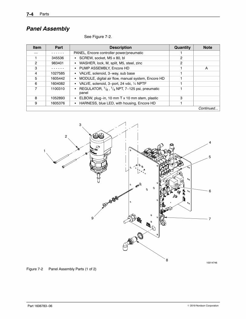
Panel Assembly See Figure 7-2.
Item Part Description Quantity Note— - - - - - - PANEL, Encore controller power/pneumatic 11 345536 � SCREW, socket, M5 x 80, bl 22 983401 � WASHER, lock, M, split, M5, steel, zinc 23 - - - - - - � PUMP ASSEMBLY, Encore HD 1 A4 1027585 � VALVE, solenoid, 3−way, sub base 15 1605442 � MODULE, digital air flow, manual system, Encore HD 16 1604082 � VALVE, solenoid, 3−port, 24 vdc, ¼ NPTF 17 1100310 � REGULATOR, 1/8 , 1/4 NPT, 7−125 psi, pneumatic
panel1
8 1052893 � ELBOW, plug−in, 10 mm T x 10 mm stem, plastic 39 1605376 � HARNESS, blue LED, with housing, Encore HD 1
Continued...
1
2
3
7
8
4
5
6
9
10014746
Figure 7-2 Panel Assembly Parts (1 of 2)
Parts 7-5
Part 1606783−06� 2019 Nordson Corporation
Panel Assembly (contd)
See Figure 7-3.
Item Part Description Quantity Note2 983401 � WASHER, lock, M, split, M5, steel, zinc 410 1606835 � PCA, replay board, Encore LT-HD 111 1107695 � POWER SUPPLY, 24 Vdc, 60 W 112 1604518 � CONNECTOR, male, elbow, 6 mm T x 1/8 RPT 313 972313 � TEE, union, 8 mm tube x 8 mm tube, pl 114 1604804 � MANIFOLD ASSEMBLY, pump control, Encore HD 115 1605754 � FILTER, line, with terminals, Encore HD 116 984702 � NUT, hex, M5, brass 417 983021 � WASHER, flat, E, 0.203 x 0.406 x 0.040, br 418 240674 � TAG, ground 2
NOTE A: Refer to the Pump section on page 7-9 to order parts.
10014746
10
11
12
13
14
15
2,16,17,18
Figure 7-3 Panel Assembly Parts (2 of 2)
Parts7-6
Part 1606783−06 � 2019 Nordson Corporation
iFlow Module See Figure 7-4.
Item Part Description Quantity Note— 1605443 MODULE, digital airflow, manual system,
Encore HD1
1 1099288 � VALVE, solenoid, 3-way, w/connector 4
2 1027547 � VALVE, proportional, solenoid, sub-base 23 1602319 � PCA, Encore HD flow node, 1 channel 1
4 972277 � CONNECTOR, male, elbow, 8 mm T x 1/4 uni 15 972399 � CONNECTOR, male, with/int hex,
6 mm T x 1/8 uni3
6 1030873 � VALVE, check, M8 TXR 1/8, M input 2
1
2
3
4
5
6
Figure 7-4 iFlow Module Parts
Parts 7-7
Part 1606783−06� 2019 Nordson Corporation
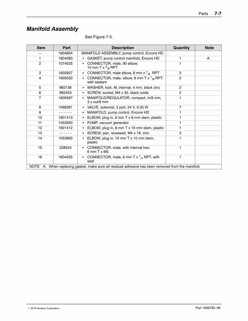
Manifold Assembly See Figure 7-5.
Item Part Description Quantity Note— 1604804 MANIFOLD ASSEMBLY, pump control, Encore HD1 1604080 � GASKET, pump control manifold, Encore HD 1 A2 1074535 � CONNECTOR, male, 90 elbow,
10 mm T x 3/8 RPT1
3 1603927 � CONNECTOR, male elbow, 8 mm x 1/8 RPT 34 1605530 � CONNECTOR, male, elbow, 6 mm T x 1/8 RPT.
with sealant2
5 983136 � WASHER, lock, M, internal, 4 mm, black zinc 26 982453 � SCREW, socket, M4 x 35, black oxide 27 1605567 � MANIFOLD/REGULATOR, compact, in/8 mm,
3 x out/6 mm1
8 1099281 � VALVE, solenoid, 3 port, 24 V, 0.35 W 79 - - - - - - � MANIFOLD, pump control, Encore HD 110 1601413 � ELBOW, plug in, 6 mm T x 8 mm stem, plastic 111 1052920 � PUMP, vacuum generator 112 1601412 � ELBOW, plug in, 8 mm T x 10 mm stem, plastic 113 - - - - - - � SCREW, pan, recessed, M4 x 16, zinc 214 1052893 � ELBOW, plug in, 10 mm T x 10 mm stem,
plastic1
15 328524 � CONNECTOR, male, with internal hex,6 mm T x M5
1
16 1604335 � CONNECTOR, male, 6 mm T x 1/4 RPT, withseal
1
NOTE A: When replacing gasket, make sure all residual adhesive has been removed from the manifold.
Parts7-8
Part 1606783−06 � 2019 Nordson Corporation
1604804
1
2
34
8
13
14
65
79
10
11
12
1516
Figure 7-5 Manifold Assembly Parts
Parts 7-9
Part 1606783−06� 2019 Nordson Corporation
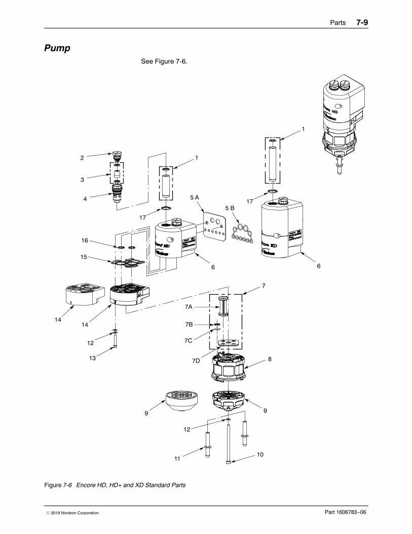
Pump
See Figure 7-6.
2
4
16
11
3
1
12
13
7
14
9
6
14
9
15
12
10
8
6
7A
7B
7C
7D
5 B
5 A17
17
1
Figure 7-6 Encore HD, HD+ and XD Standard Parts
Parts7-10
Part 1606783−06 � 2019 Nordson Corporation
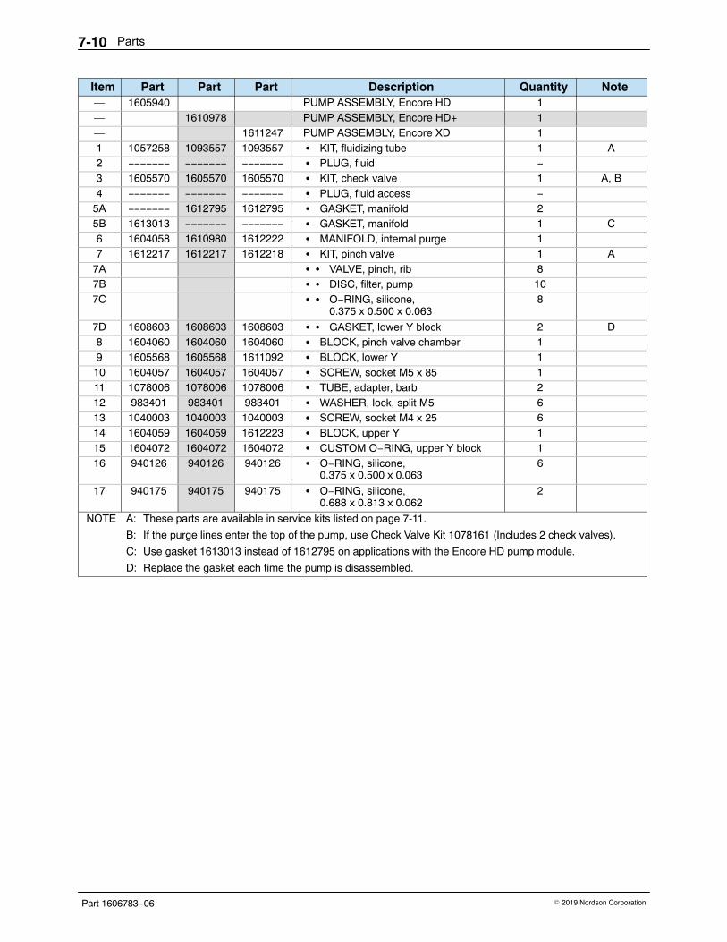
Item Part Part Part Description Quantity Note— 1605940 PUMP ASSEMBLY, Encore HD 1— 1610978 PUMP ASSEMBLY, Encore HD+ 1— 1611247 PUMP ASSEMBLY, Encore XD 11 1057258 1093557 1093557 � KIT, fluidizing tube 1 A2 −−−−−−− −−−−−−− −−−−−−− � PLUG, fluid −3 1605570 1605570 1605570 � KIT, check valve 1 A, B4 −−−−−−− −−−−−−− −−−−−−− � PLUG, fluid access −
1067694 KIT, ground bus bar, ESD, 6 position, with hardware 1
1080718 CABLE, interface/controller, 10 ft. 1
NOTE A: Installed in power unit fluidizing air output fitting.
Powder Hose and Air Tubing Powder hose and air tubing must be ordered in increments of one foot.
Part Description Note1613849 Powder hose, 6 mm ID x 8 mm OD, polyolefin (by 40 m) B, F
1613850 Powder hose, 6 mm ID x 8 mm OD, polyolefin (by 160 m) C, F
1615026 Clear powder hose, 6 mm ID x 8 mm OD, polyurethane (by 60 ft) G
1606695 Clear powder hose, 6 mm ID x 8 mm OD, polyurethane (by 500 ft) D, G
900617 Air tubing, polyurethane, 4 mm, clear, electrode air wash A
900742 Air tubing, polyurethane, 6 mm, blue, pattern air A
1096789 Air tubing, antistatic, 6/4 mm, black (conductive air tubing),VBF pickup tube to controller
E
900741 Air tubing, polyurethane, 6 mm, black
900618 Air tubing, polyurethane, 8 mm, blue A
900619 Air tubing, polyurethane, 8 mm, black A
900740 Air tubing, polyurethane, 10 mm, blue, main air IN A
900517 Tubing, poly, spiral cut, 0.62 in. ID, dress out
301841 Strap, Velcro, w/buckle, 25 x 3 cm, dress out
NOTE A: Minimum order quantity is 50 ft.
B: Minimum order quantity is 40 m.
C: Minimum order is 160 m.
D: Minimum order quantity is 500 ft.
E: This tubing is used on VBF systems to provide fluidizing air from the bulkhead union to the pickup tube. Itis conductive and grounds the pickup tube to the cart body. Do not replace with non-conductive tubing.
F: Standard powder hose delivered with system.
G: Optional powder hose to use in place of the standard polyolefin.
Parts 7-13
Part 1606783−06� 2019 Nordson Corporation
Miscellaneous Options
Part Description Quantity Note1091429 KIT, input air, Encore HD manual systems 1
972841 � CONNECTOR, male, 10 mm tube x 1/4 in. unithread 1
971102 � CONNECTOR, male, 10 mm tube x 3/8 in. unithread 1
900740 � TUBING, polyurethane, 10 mm, blue 20 ft A
1096786 FILTER/REGULATOR, assembly, with fittings (particulate) 1 B
1097103 � FILTER ELEMENT, air, 5 micron 1 B
NOTE A: Order replacement tubing in increments of one foot.
B: OEM assembly part number AW20−02BE−CR. Order the correct filter element for your filter/regulator.Elements are not interchangeable.
Parts7-14
Part 1606783−06 � 2019 Nordson Corporation
Your notes
Wiring Diagrams 8-1
Part 1606783−06� 2019 Nordson Corporation
Section 8Wiring Diagrams
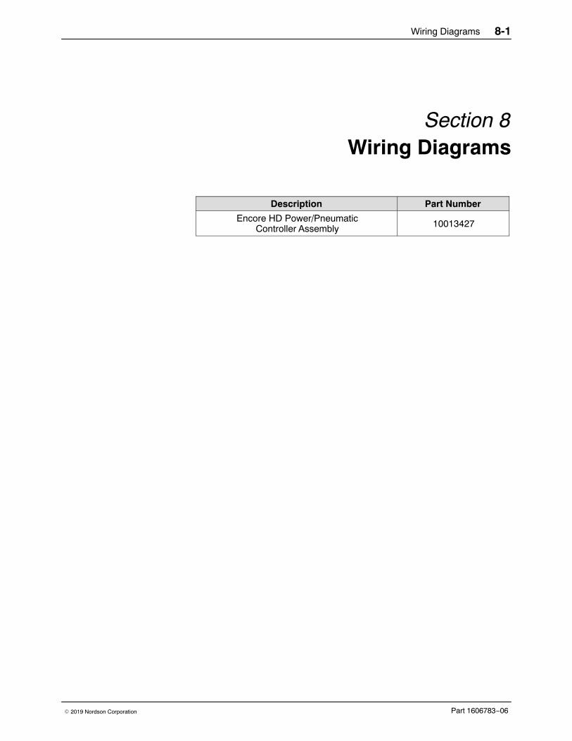
Description Part Number
Encore HD Power/PneumaticController Assembly 10013427
Wiring Diagrams8-2
Part 1606783−06 � 2019 Nordson Corporation
VENT TO BACKOF HOUSING V
FLOW AIR TO TOP OF HOUSING N
ELECTRODE AIR WASH S
VENT TO BACKOF HOUSING U
PURGE P - 6mm PLUG
FLUIDIZING R
AIR IN FRONT PANEL
AIR IN FRONT PANEL
TO FITTINGS ON HOUSING29
ATOMIZING AIRTOP OF HOUSING T
SET TO 85 PSI
W
W
59
G
G FLUIDIZING
FLOW AIR
PURGE AIR
ELECTRODE AIR WASH
ATOMIZING AIR
TOP VIEW OF HOUSING
BOTTOM VIEW MANIFOLD
PINCH EXHAUSTTO BACK OF HOUSING
34
34
ROUTE ITEM 23 HERE
DETAIL E SCALE 1 : 1
REMOVE JUMPER FOR 230V APPLICATION
NUMBER REVISION
REF DWG,PWR/PNEU CTRLR ASSY,ENCORE HDDESCRIPTION
0610013427 SHEET 3OF2
ENCOREDIGITAL AIRFLOW
CONTROL MODULE
iFLOWDIGITAL FLOW CONTROL PCA
J9 (VBF)
(GREEN/YELLOW)
(BLUE)(BROWN)
(BLACK)(RED)
(BLACK)(RED)
(BLACK)(RED)
FLOW
ATOMIZING
(BLUE)(BROWN)
(GREEN/YELLOW)
BOOST
NOZZLE
FLUIDIZING
PURGE
12
J5
12
J4
12
3
J8
12
3J7
J10 12
J3 (NET/PWR)54312 6
12J6
12653 4
+24VDC
DC COM
DC COM
+24VDC
1 2J2 (POWER)
(BLACK)(RED)
J11 J12
7
6
4
5
3
2 1
1 2
3
4
5 6
SK 2
N
LSK 1
POWER SUPPLY
13
GRE
EN
BLUE
WHI
TE
BLA
CK
RED
NETWORK
RELAYBOARD
12
F1
F2
RL1C1 C2
JP1
L2F
L2
L1F
L1
M3M2M1
ATTACH NUMBEREDWIRE GROUPS TOCORRESPONDING VALVE NUMBER
23
JUMPER120v VBF ONLY
GNDINSIDE TOP OF HOUSING
GNDINSIDE TOP OF HOUSING
CONNECTORFOR LED
(GREEN/YELLOW)
GND
BLUE
BROWN
FILTER
RED
GREEN
BLACKWHITE
BLUE
BROWN
NC
BLUE
BROWN
BLACK
(GREEN/YELLOW)
BLACK DC COMM
RED + 24VDCRED + 24VDC
BLACK DC COMM
VBF RECEPTACLE
BLACK
BLACK
BLACK
BLA
CK
RED
BLA
CK
RED
9
8
10
9
8
10
1
2
34
5
6
7
BLUE
WHITE
BLACK
RED
GNDHA
RD P
URG
E
PIN
CH
HI/L
O S
ELEC
T
3 OF 3SHEET10013427 06
DESCRIPTION REF DWG,PWR/PNEU CTRLR ASSY,ENCORE HD
REVISIONNUMBER
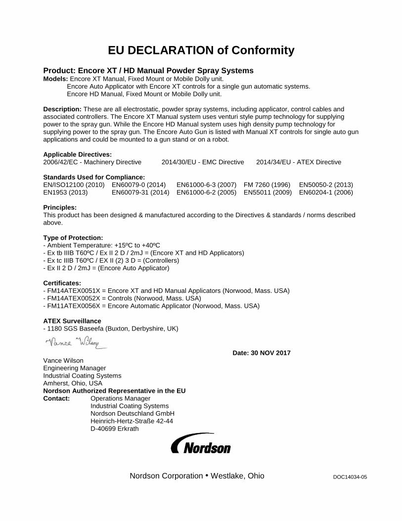
EU DECLARATION of Conformity Product: Encore XT / HD Manual Powder Spray Systems Models: Encore XT Manual, Fixed Mount or Mobile Dolly unit. Encore Auto Applicator with Encore XT controls for a single gun automatic systems. Encore HD Manual, Fixed Mount or Mobile Dolly unit. Description: These are all electrostatic, powder spray systems, including applicator, control cables and associated controllers. The Encore XT Manual system uses venturi style pump technology for supplying power to the spray gun. While the Encore HD Manual system uses high density pump technology for supplying power to the spray gun. The Encore Auto Gun is listed with Manual XT controls for single auto gun applications and could be mounted to a gun stand or on a robot. Applicable Directives: 2006/42/EC - Machinery Directive 2014/30/EU - EMC Directive 2014/34/EU - ATEX Directive Standards Used for Compliance: EN/ISO12100 (2010) EN60079-0 (2014) EN61000-6-3 (2007) FM 7260 (1996) EN50050-2 (2013) EN1953 (2013) EN60079-31 (2014) EN61000-6-2 (2005) EN55011 (2009) EN60204-1 (2006) Principles: This product has been designed & manufactured according to the Directives & standards / norms described above. Type of Protection: - Ambient Temperature: +15ºC to +40ºC - Ex tb IIIB T60ºC / Ex II 2 D / 2mJ = (Encore XT and HD Applicators) - Ex tc IIIB T60ºC / EX II (2) 3 D = (Controllers) - Ex II 2 D / 2mJ = (Encore Auto Applicator) Certificates: - FM14ATEX0051X = Encore XT and HD Manual Applicators (Norwood, Mass. USA) - FM14ATEX0052X = Controls (Norwood, Mass. USA) - FM11ATEX0056X = Encore Automatic Applicator (Norwood, Mass. USA) ATEX Surveillance - 1180 SGS Baseefa (Buxton, Derbyshire, UK)
Date: 30 NOV 2017 Vance Wilson Engineering Manager Industrial Coating Systems Amherst, Ohio, USA Nordson Authorized Representative in the EU Contact: Operations Manager Industrial Coating Systems Nordson Deutschland GmbH Heinrich-Hertz-Straße 42-44 D-40699 Erkrath