Page 1
Title page
1645 Access Multiplexer Compact AMCRelease 8.0Installation Guide
365-313-103R8.0
CC109642231
ISSUE 2
JULY 2009
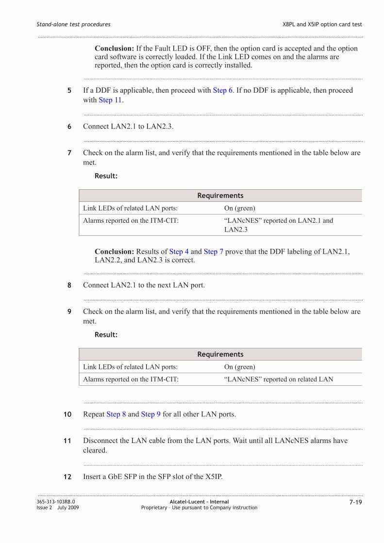
Alcatel-Lucent – InternalProprietary – Use pursuant to Company instruction
Proprietary – Use pursuant to Company instruction
Page 2
Legal notice
Legal notice
Alcatel, Lucent, Alcatel-Lucent and the Alcatel-Lucent logo are trademarks of Alcatel-Lucent. All other trademarks are the property of their respective
owners.
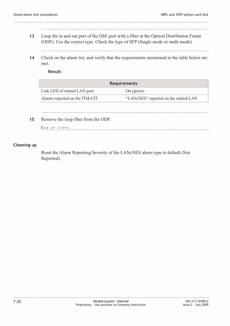
The information presented is subject to change without notice. Alcatel-Lucent assumes no responsibility for inaccuracies contained herein.
Copyright © 2009 Alcatel-Lucent. All rights reserved.
Contains proprietary/trade secret information which is the property of Alcatel-Lucent and must not be made available to, or copied or used by anyone outside
Alcatel-Lucent without its written authorization.
ot to be used or disclosed except in accordance with applicable agreements.
Notice
Every effort has been made to ensure that the information in this document was complete and accurate at the time of printing. However, information is
subject to change.
Release notification
This document describes 1645 AMC release 8.0.
Safety
Always observe the Safety Instructions given in Chapter 1 when operating the system.
Please note that Alcatel-Lucent warranty is contingent upon the use of Alcatel-Lucent specified SFPs for AMC. Use of other SFPs is not approved by
Alcatel-Lucent and is fully at the customer's own risk. Any warranty obligation of Alcatel-Lucent is extinguished when non-Alcatel-Lucent specified SFPs
are used.
Ordering information
The order number of this document is 365-313-103R8.0.
Technical support
Please contact your Alcatel-Lucent Local Customer Support Team for technical questions about the information in this document.
Information product support
To comment on this information product online, go to http://www.lucent-info.com/comments or email your comments to [email protected] .
Proprietary – Use pursuant to Company instruction
Alcatel-Lucent – InternalProprietary – Use pursuant to Company instruction
Page 3
Contents
About this document
Purpose ............................................................................................................................................................................................ xvxv
Safety information ....................................................................................................................................................................... xvxv
Intended audience ........................................................................................................................................................................ xvxv
How to use this information product .................................................................................................................................... xvxv
Conventions used ....................................................................................................................................................................... xvixvi
Related documentation ........................................................................................................................................................... xviixvii
Technical support ..................................................................................................................................................................... xviiixviii
How to order ................................................................................................................................................................................ xixxix
How to comment ........................................................................................................................................................................ xixxix
Part I: Physical and power installation
1 Safety
Overview ....................................................................................................................................................................................... 1-11-1
General notes on safety
Overview ....................................................................................................................................................................................... 1-31-3
Structure of safety statements ................................................................................................................................................ 1-31-3
Basic safety aspects ................................................................................................................................................................... 1-61-6
Specific safety areas
Overview ....................................................................................................................................................................................... 1-81-8
Laser safety .................................................................................................................................................................................. 1-81-8
Optical circuit pack specifications .................................................................................................................................... 1-111-11
Power supply safety instructions ....................................................................................................................................... 1-111-11
...................................................................................................................................................................................................................................
365-313-103R8.0Issue 2 July 2009
Alcatel-Lucent – InternalProprietary – Use pursuant to Company instruction
iii
Page 4
Electrostatic discharge ........................................................................................................................................................... 1-121-12
Conformity statements ........................................................................................................................................................... 1-131-13
2 General information
Overview ....................................................................................................................................................................................... 2-12-1
Hardware description ............................................................................................................................................................... 2-12-1
Environmental considerations ............................................................................................................................................... 2-82-8
EMC/ESD information ............................................................................................................................................................ 2-92-9
ITM-CIT requirements .......................................................................................................................................................... 2-102-10
Required tools and test equipment .................................................................................................................................... 2-112-11
Sequence of steps .................................................................................................................................................................... 2-122-12
3 Mechanical installation
Overview ....................................................................................................................................................................................... 3-13-1
1645 AMC installation
Overview ....................................................................................................................................................................................... 3-23-2
Technical data for AMC unit ................................................................................................................................................ 3-23-2
Installation of an option card ................................................................................................................................................. 3-53-5
Mounting the EMC bracket .................................................................................................................................................... 3-73-7
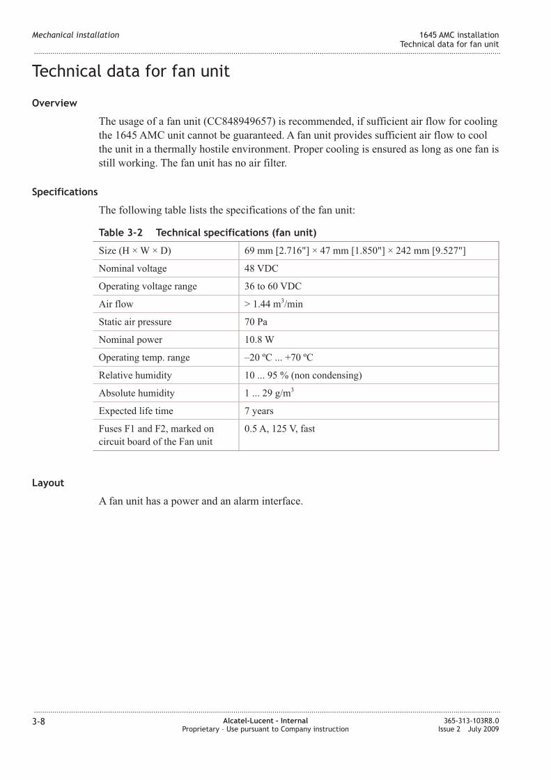
Technical data for fan unit ...................................................................................................................................................... 3-83-8
AMC unit installation ............................................................................................................................................................ 3-103-10
4 System cabling
Overview ....................................................................................................................................................................................... 4-14-1
Power and ground cable installation
Overview ....................................................................................................................................................................................... 4-34-3
Power interfaces ........................................................................................................................................................................ 4-34-3
Ground wiring ............................................................................................................................................................................. 4-54-5
External cable installation
Overview ....................................................................................................................................................................................... 4-64-6
Fan power interface ................................................................................................................................................................... 4-64-6
Contents
...................................................................................................................................................................................................................................
...................................................................................................................................................................................................................................
iv Alcatel-Lucent – InternalProprietary – Use pursuant to Company instruction
365-313-103R8.0Issue 2 July 2009
Page 5
Fan alarm and LED interface ................................................................................................................................................ 4-84-8
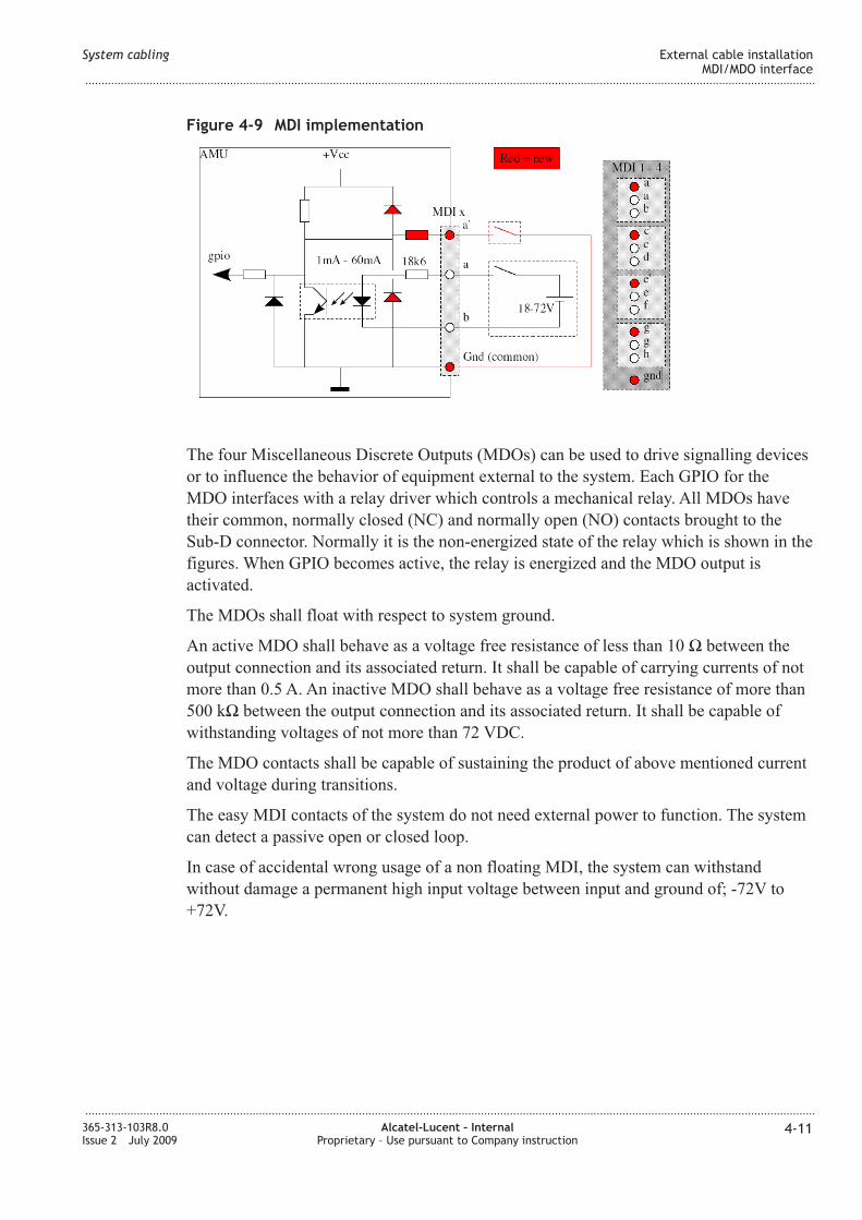
MDI/MDO interface ............................................................................................................................................................... 4-104-10
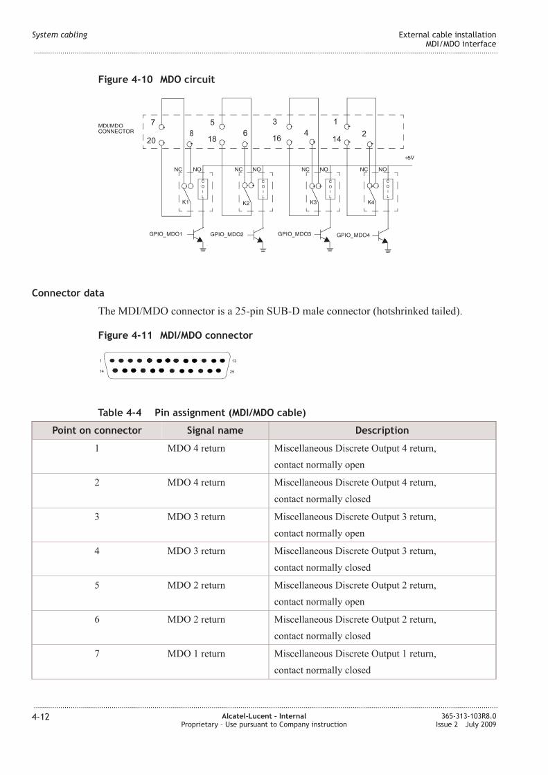
Synchronization interface ..................................................................................................................................................... 4-144-14
Timing interface ....................................................................................................................................................................... 4-164-16
Q-LA interface (OMS) ....................................................................................................................................................... 4-174-17
ITM-CIT interface ................................................................................................................................................................... 4-194-19
EOW interfaces ........................................................................................................................................................................ 4-204-20
Option card cable installation
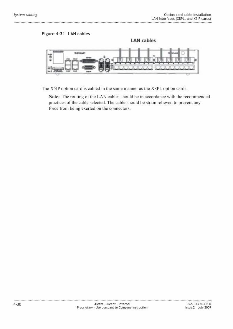
Overview .................................................................................................................................................................................... 4-224-22
E1 interfaces (Main board/X16E1-V3 card) ................................................................................................................. 4-224-22
DS1 interfaces (Main board/X16DS1 card) .................................................................................................................. 4-244-24
SHDSL interfaces (X12SHDSL-V2 card) ..................................................................................................................... 4-254-25
E3/DS3 interfaces (X3E3DS3 card) ................................................................................................................................. 4-274-27
LA interfaces (X8PL, and X5IP cards) ........................................................................................................................ 4-284-28
Fiber cabling
Overview .................................................................................................................................................................................... 4-314-31
Optical interfaces ................................................................................................................................................................... 4-314-31
SFP-155E cable ........................................................................................................................................................................ 4-334-33
Optical interfaces (X5IP card) ............................................................................................................................................ 4-334-33
Optical interfaces (X6STM1 card) .................................................................................................................................... 4-354-35
Aggregate interfaces (Main board) ................................................................................................................................... 4-364-36
5 Powering
Overview ....................................................................................................................................................................................... 5-15-1
Power initialization
Overview ....................................................................................................................................................................................... 5-25-2
Switching on and testing supply voltage ........................................................................................................................... 5-35-3
Fan unit test .................................................................................................................................................................................. 5-45-4
Contents
...................................................................................................................................................................................................................................
...................................................................................................................................................................................................................................
365-313-103R8.0Issue 2 July 2009
Alcatel-Lucent – InternalProprietary – Use pursuant to Company instruction
v
Page 6
Physical installation check
Overview ....................................................................................................................................................................................... 5-55-5
AMC unit installation ............................................................................................................................................................... 5-55-5
Cable connections ...................................................................................................................................................................... 5-65-6
Physical and power installation exit checklist ................................................................................................................. 5-65-6
Part II: NE provisioning and stand-alone installation test
6 ITM-CIT installation and NE provisioning
Overview ....................................................................................................................................................................................... 6-16-1
Software installation
Overview ....................................................................................................................................................................................... 6-26-2
Installing ITM-CIT .................................................................................................................................................................... 6-36-3
Installing the fast download application ............................................................................................................................ 6-76-7
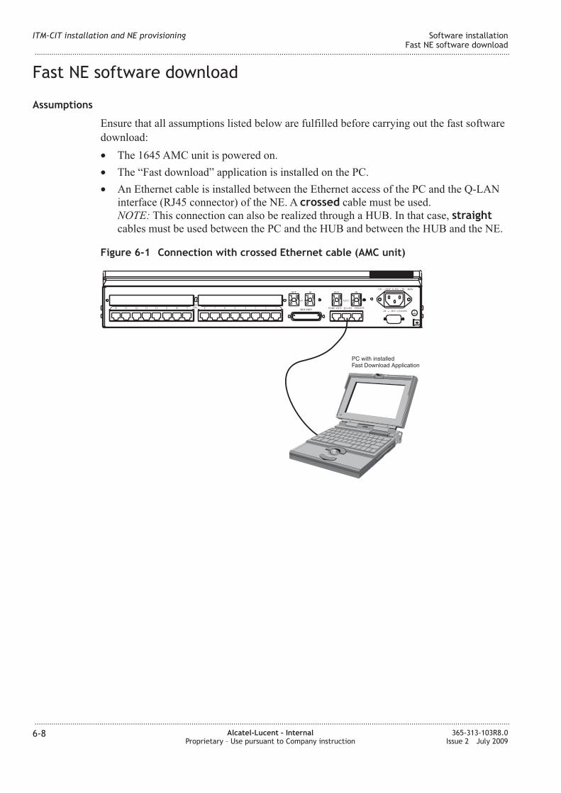
Fast E software download ................................................................................................................................................... 6-86-8
Connecting the ITM-CIT to the E .................................................................................................................................. 6-106-10
E login procedure ................................................................................................................................................................. 6-126-12
Provisioning system parameters
Overview .................................................................................................................................................................................... 6-146-14
E date and time ..................................................................................................................................................................... 6-156-15
ode creation ............................................................................................................................................................................ 6-176-17
Slot provisioning ...................................................................................................................................................................... 6-206-20
Confirm/Update the MIB ..................................................................................................................................................... 6-226-22
7 Stand-alone test procedures
Overview ....................................................................................................................................................................................... 7-17-1
Test equipment and accessories ............................................................................................................................................ 7-27-2
Preparation and test of the main unit .................................................................................................................................. 7-47-4
E1 tributary ports distribution wiring test ......................................................................................................................... 7-57-5
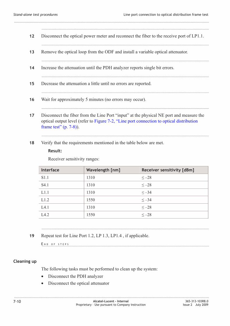
Line port connection to optical distribution frame test ................................................................................................ 7-87-8
PDH option card test .............................................................................................................................................................. 7-127-12
Contents
...................................................................................................................................................................................................................................
...................................................................................................................................................................................................................................
vi Alcatel-Lucent – InternalProprietary – Use pursuant to Company instruction
365-313-103R8.0Issue 2 July 2009
Page 7
Optical X6STM1 option card test ..................................................................................................................................... 7-157-15
X8PL and X5IP option card test ........................................................................................................................................ 7-187-18
X12SHDSL-V2 option card test ........................................................................................................................................ 7-217-21
E provisioning and stand alone installation test exit checklist ............................................................................ 7-237-23
Part III: Link testing
8 Link testing
Overview ....................................................................................................................................................................................... 8-18-1
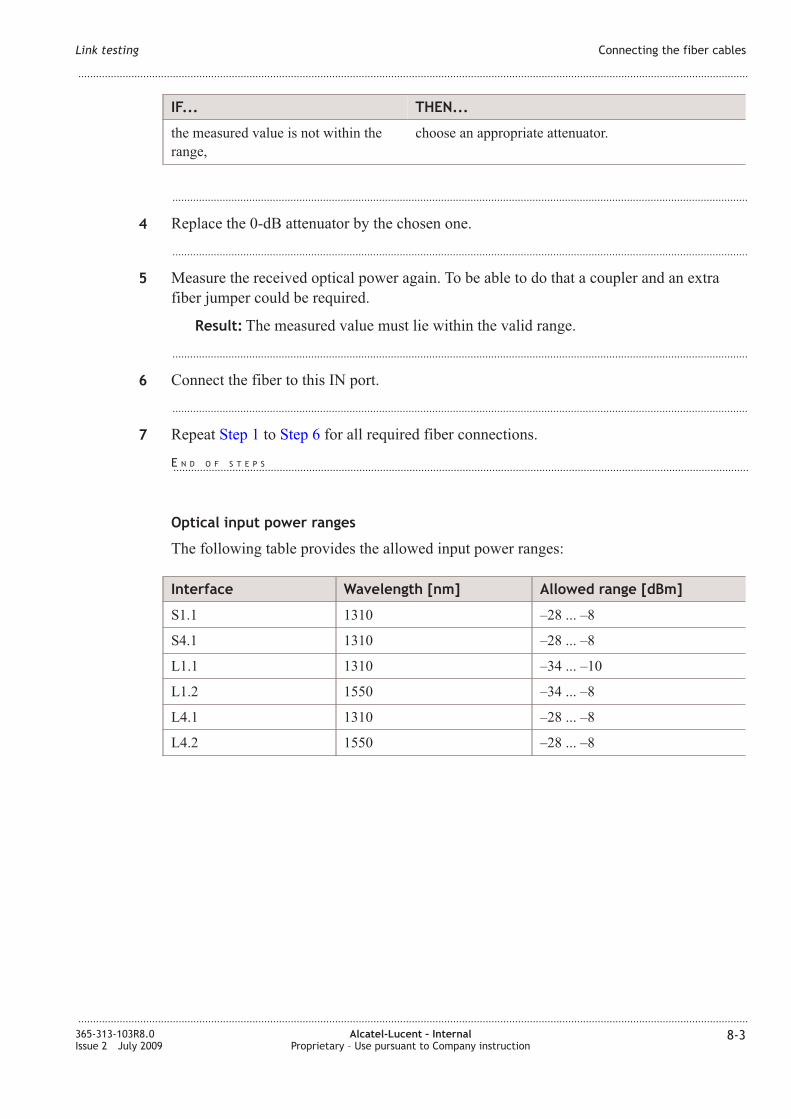
Connecting the fiber cables .................................................................................................................................................... 8-28-2
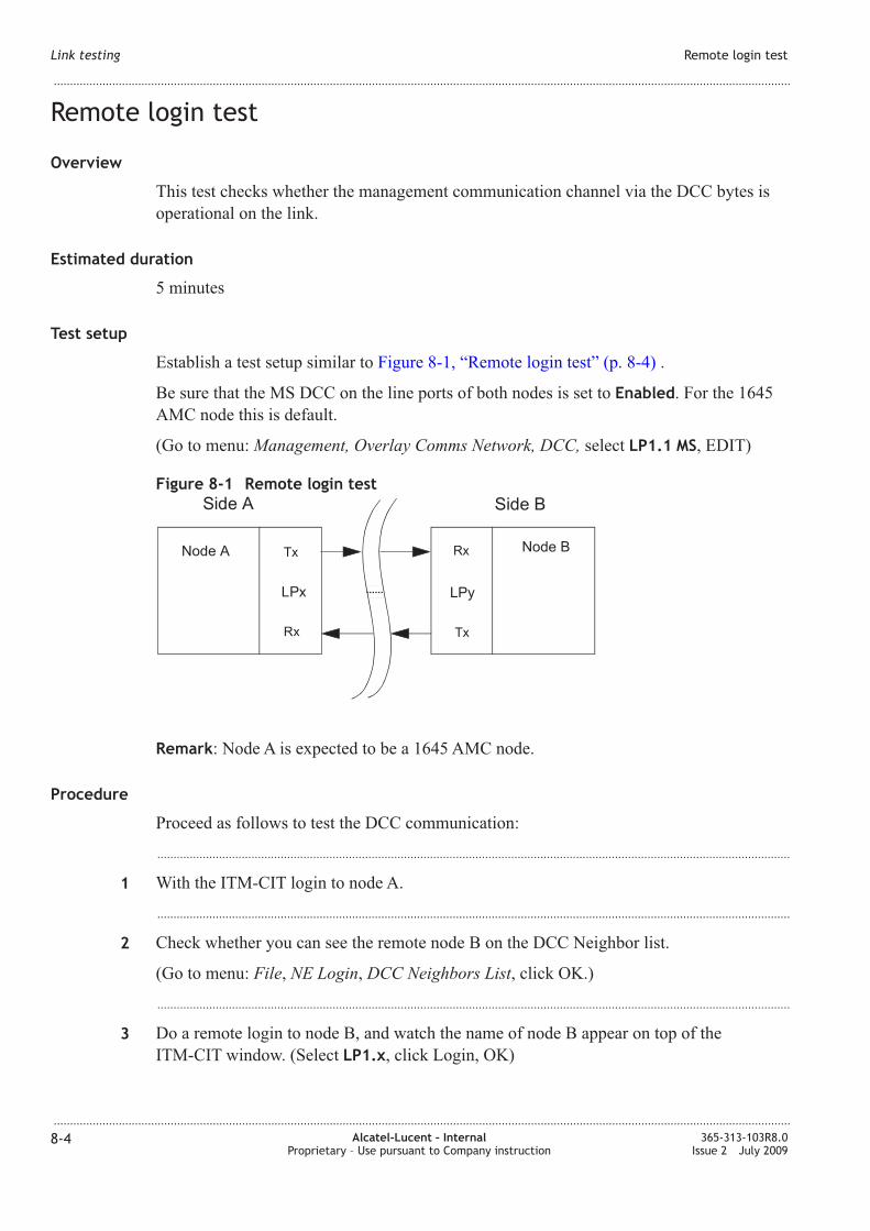
Remote login test ....................................................................................................................................................................... 8-48-4
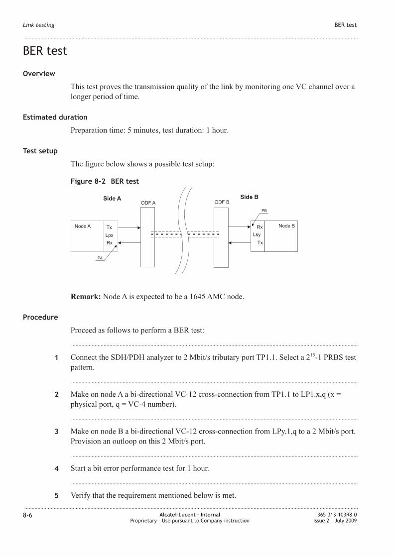
BER test ......................................................................................................................................................................................... 8-68-6
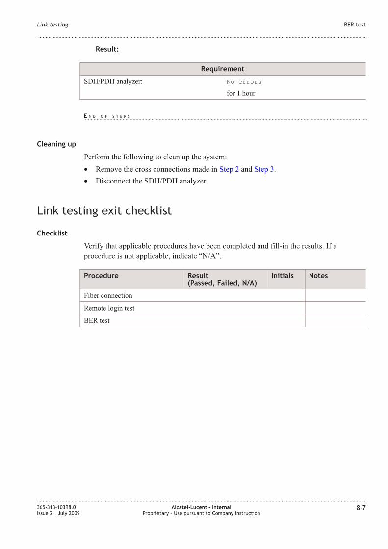
Link testing exit checklist ....................................................................................................................................................... 8-78-7
9 Conclusion
Overview ....................................................................................................................................................................................... 9-19-1
Power supply measurements .................................................................................................................................................. 9-19-1
Optical output power measurements ................................................................................................................................... 9-29-2
Final checklist ............................................................................................................................................................................. 9-39-3
A Mounting rules
Overview ......................................................................................................................................................................................A-1A-1
AMC units (DC powered) ..................................................................................................................................................... A-2A-2
AMC units (AC powered) ..................................................................................................................................................... A-2A-2
B Installation trouble shooting
Overview ...................................................................................................................................................................................... B-1B-1
Power failure ............................................................................................................................................................................... B-2B-2
Installing the E software ..................................................................................................................................................... B-4B-4
Parameters for E software installation ........................................................................................................................... B-6B-6
Fiber cleaning ............................................................................................................................................................................. B-8B-8
Removing the SFP modules ................................................................................................................................................ B-10B-10
Contents
...................................................................................................................................................................................................................................
...................................................................................................................................................................................................................................
365-313-103R8.0Issue 2 July 2009
Alcatel-Lucent – InternalProprietary – Use pursuant to Company instruction
vii
Page 8
C Cable assembly instructions
Overview ...................................................................................................................................................................................... C-1C-1
SUB-D connector ...................................................................................................................................................................... C-2C-2
Coax connector (1.6/5.6) ........................................................................................................................................................ C-5C-5
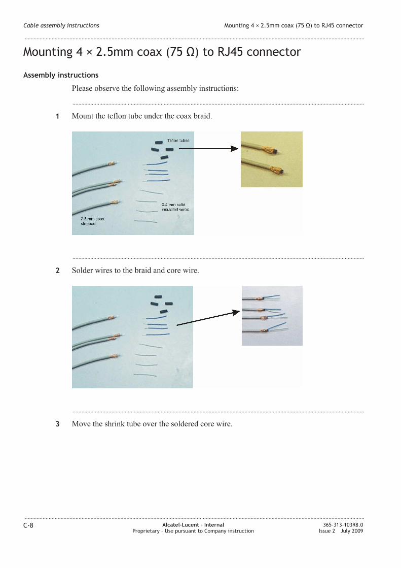
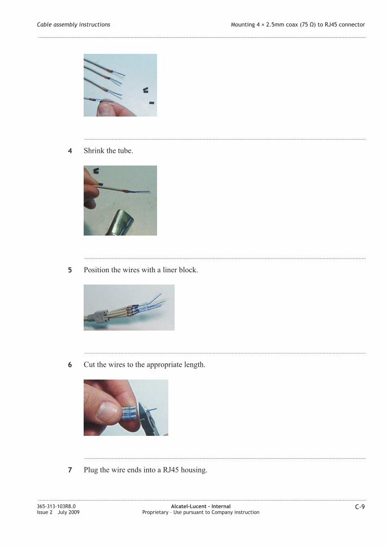
Mounting 4 × 2.5mm coax (75 Ω) to RJ45 connector ................................................................................................. C-8C-8
Glossary
Index
Contents
...................................................................................................................................................................................................................................
...................................................................................................................................................................................................................................
viii Alcatel-Lucent – InternalProprietary – Use pursuant to Company instruction
365-313-103R8.0Issue 2 July 2009
Page 9
List of tables
2-1 Technical specifications (AC/DC converter) ................................................................................................... 2-22-2
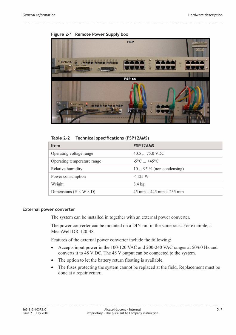
2-2 Technical specifications (FSP12AMS) .............................................................................................................. 2-32-3
2-3 Available option cards .............................................................................................................................................. 2-72-7
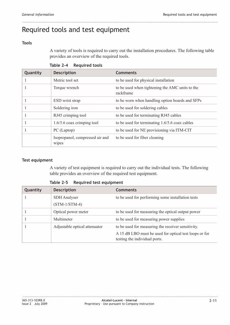
2-4 Required tools ........................................................................................................................................................... 2-112-11
2-5 Required test equipment ....................................................................................................................................... 2-112-11
3-1 Technical specifications ......................................................................................................................................... 3-23-2
3-2 Technical specifications (fan unit) ....................................................................................................................... 3-83-8
4-1 Pin assignment (power cables) ............................................................................................................................. 4-34-3
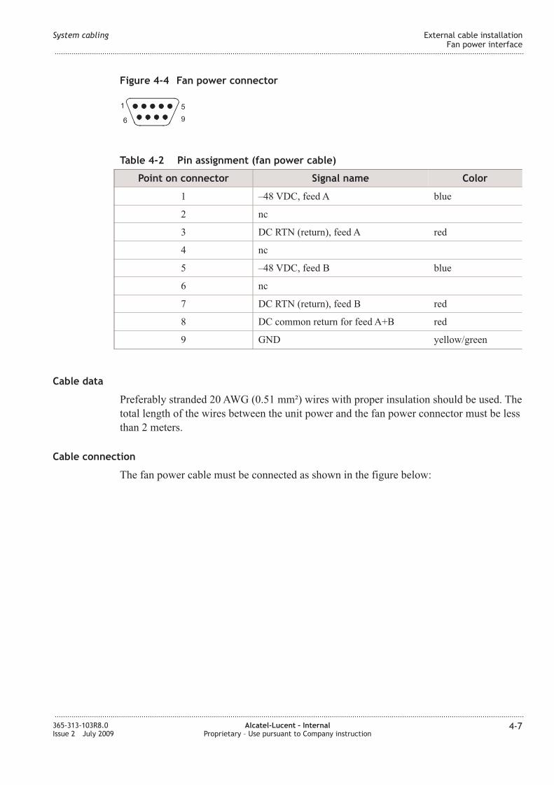
4-2 Pin assignment (fan power cable) ........................................................................................................................ 4-74-7
4-3 Pin assignment (fan alarm cable) ......................................................................................................................... 4-84-8
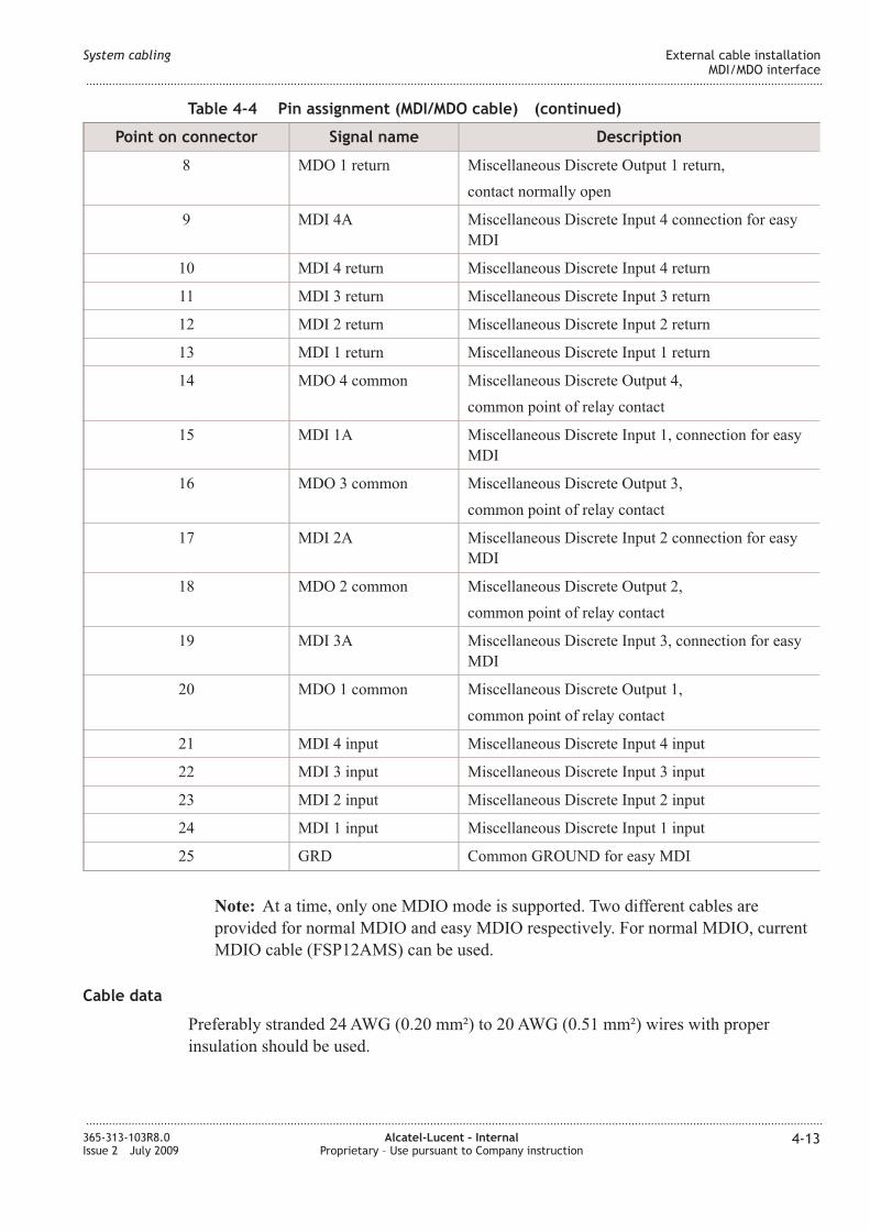
4-4 Pin assignment (MDI/MDO cable) ................................................................................................................... 4-124-12
4-5 Return loss of 30 channel market station clock inputs .............................................................................. 4-144-14
4-6 Jitter tolerance at 30 channel market station clock inputs ........................................................................ 4-154-15
4-7 Pin assignment (timing cable) ............................................................................................................................ 4-164-16
4-8 Pin assignment (Q-LA cable) .......................................................................................................................... 4-174-17
4-9 Pin assignment (ITM-CIT cable) ...................................................................................................................... 4-194-19
4-10 Pin assignment (EOW cables, valid for both connectors) ........................................................................ 4-204-20
4-11 Pin assignment (E1 cables) .................................................................................................................................. 4-224-22
4-12 Pin assignment (DS1 cables) .............................................................................................................................. 4-244-24
4-13 Pin assignment (SHDSL cables) ........................................................................................................................ 4-254-25
4-14 Pin assignment (LA cables - E/FE) ............................................................................................................... 4-284-28
4-15 Pin assignment (LA cable - GE) .................................................................................................................... 4-294-29
...................................................................................................................................................................................................................................
365-313-103R8.0Issue 2 July 2009
Alcatel-Lucent – InternalProprietary – Use pursuant to Company instruction
ix
Page 10
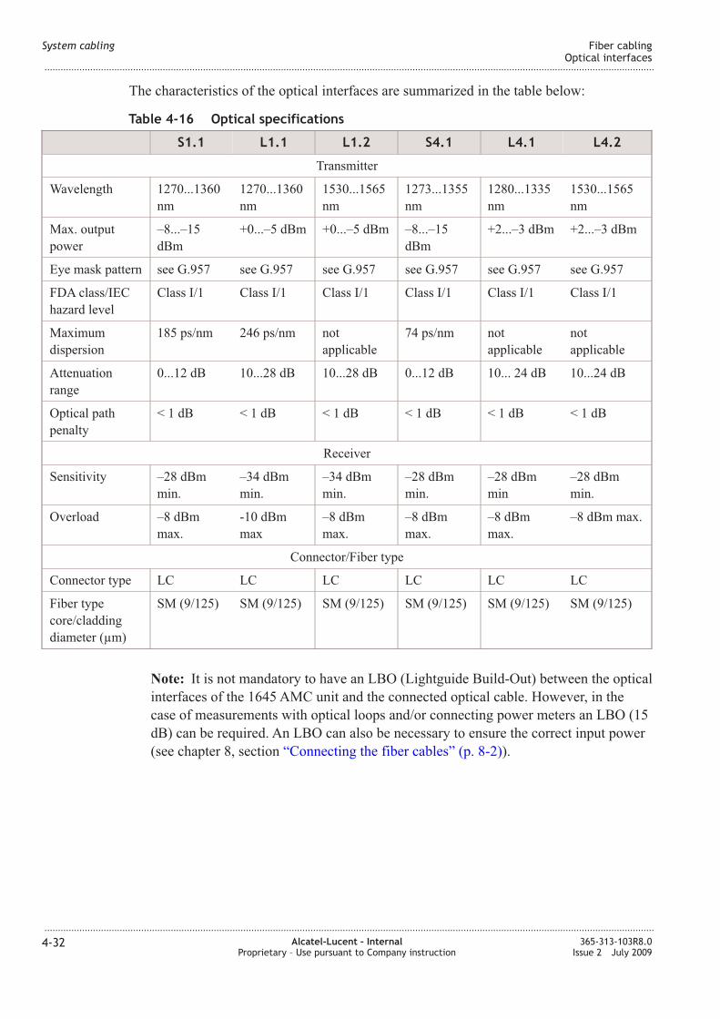
4-16 Optical specifications ............................................................................................................................................ 4-324-32
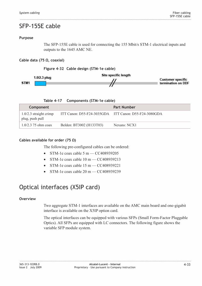
4-17 Components (STM-1e cable) .............................................................................................................................. 4-334-33
4-18 Optical SFP specifications ................................................................................................................................... 4-354-35
List of tables
...................................................................................................................................................................................................................................
...................................................................................................................................................................................................................................
x Alcatel-Lucent – InternalProprietary – Use pursuant to Company instruction
365-313-103R8.0Issue 2 July 2009
Page 11
List of figures
2-1 Remote Power Supply box ..................................................................................................................................... 2-32-3
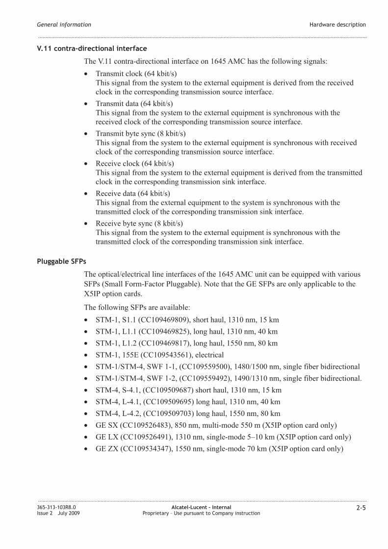
2-2 Optical SFP module .................................................................................................................................................. 2-62-6
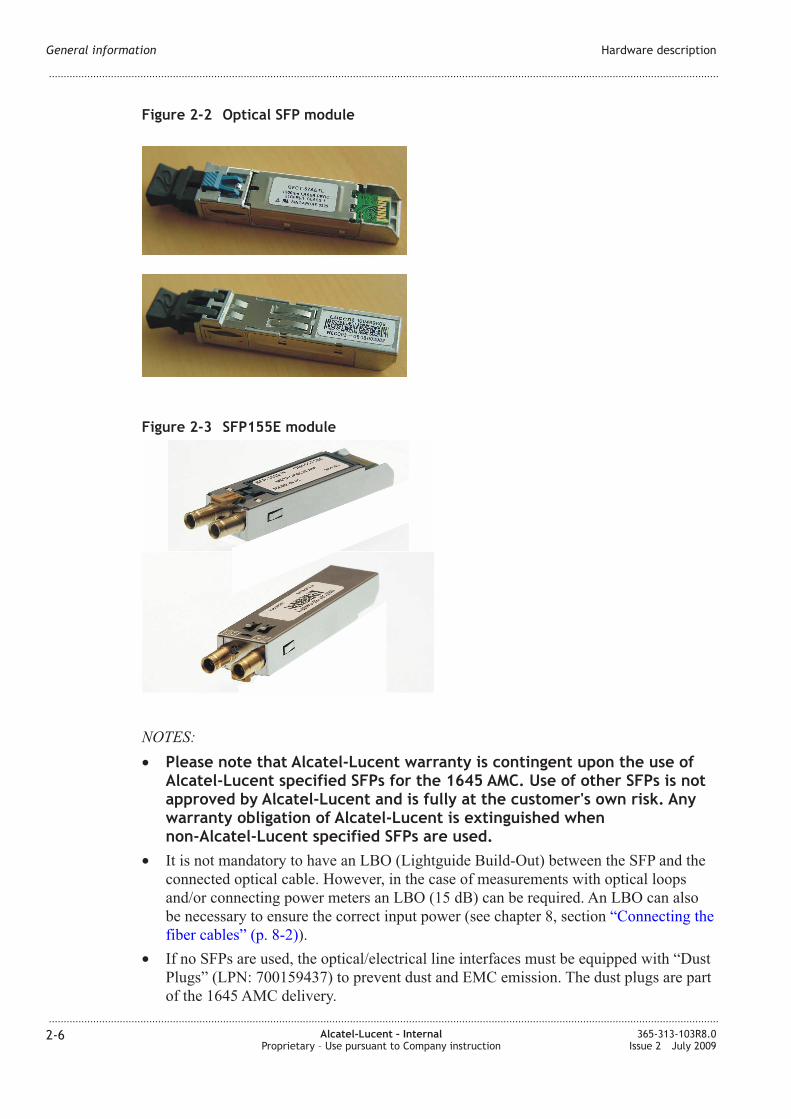
2-3 SFP155E module ....................................................................................................................................................... 2-62-6
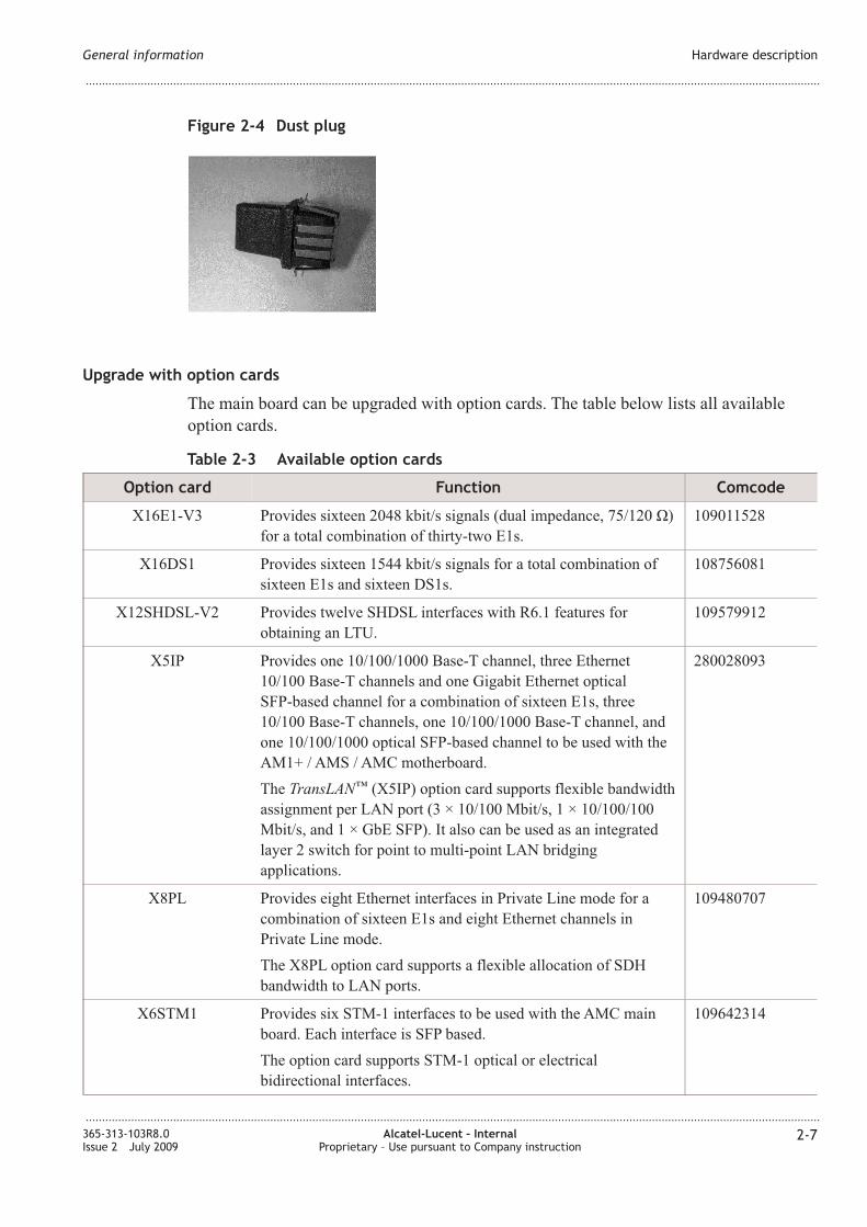
2-4 Dust plug ....................................................................................................................................................................... 2-72-7
2-5 Example of an option card ..................................................................................................................................... 2-82-8
3-1 AMC unit DC version front view ....................................................................................................................... 3-33-3
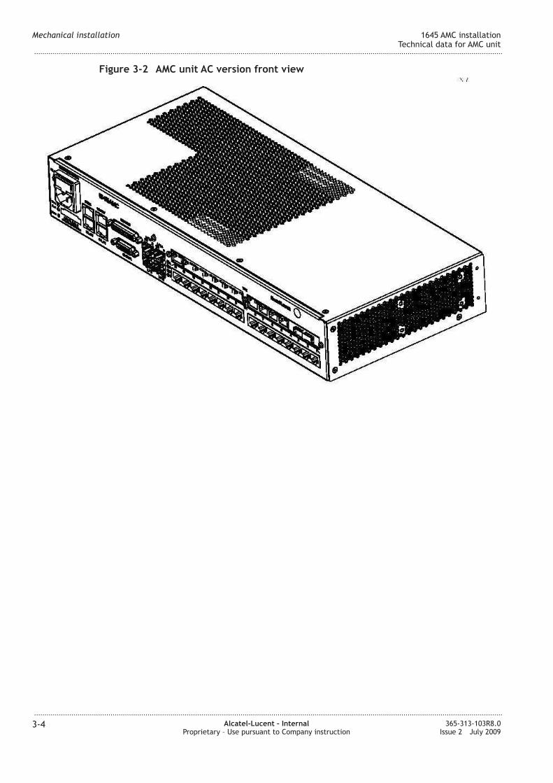
3-2 AMC unit AC version front view ........................................................................................................................ 3-43-4
3-3 Installation of an AMC option card .................................................................................................................... 3-63-6
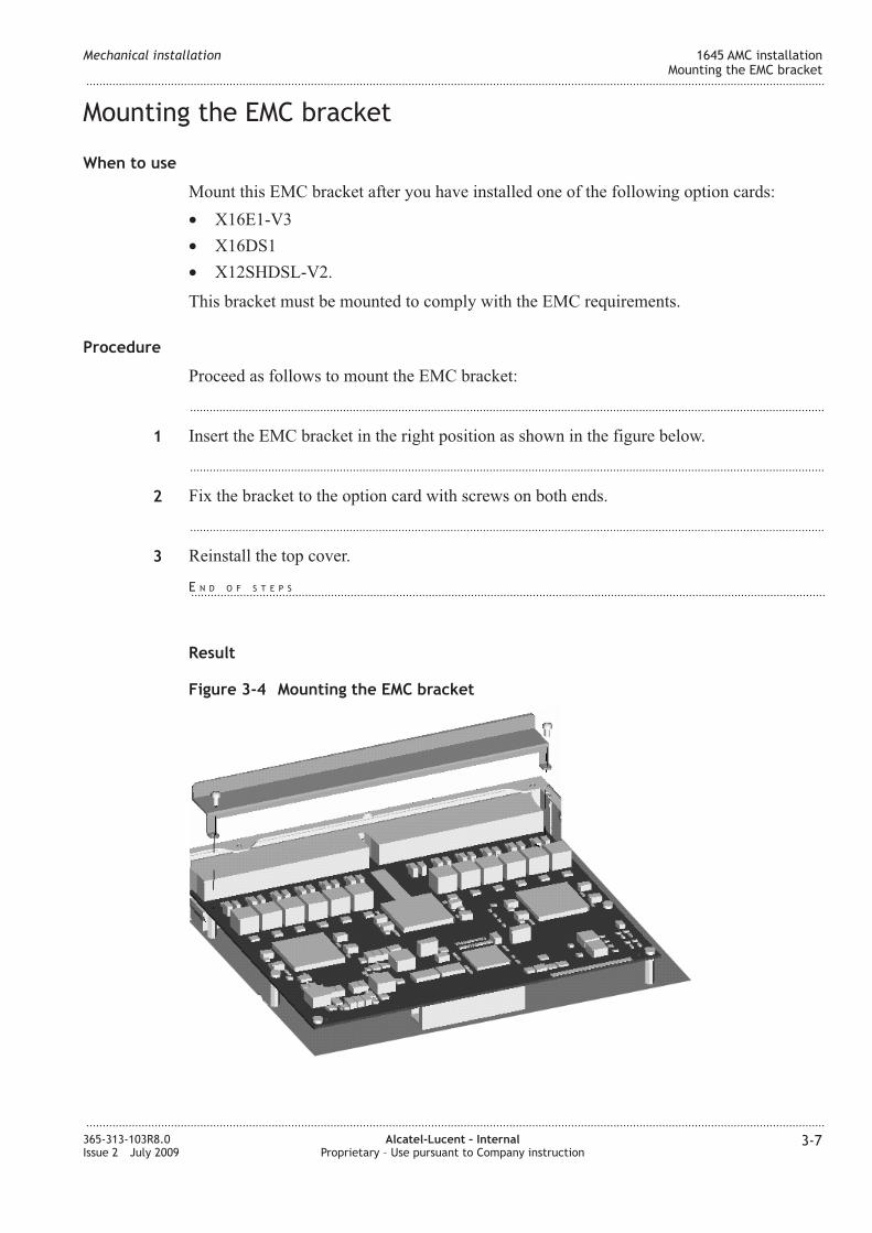
3-4 Mounting the EMC bracket .................................................................................................................................. 3-73-7
3-5 Fan unit .......................................................................................................................................................................... 3-93-9
3-6 Fixing wall mounting brackets (AMC unit) .................................................................................................. 3-113-11
3-7 Vertical wall mounting (AMC unit) ................................................................................................................. 3-123-12
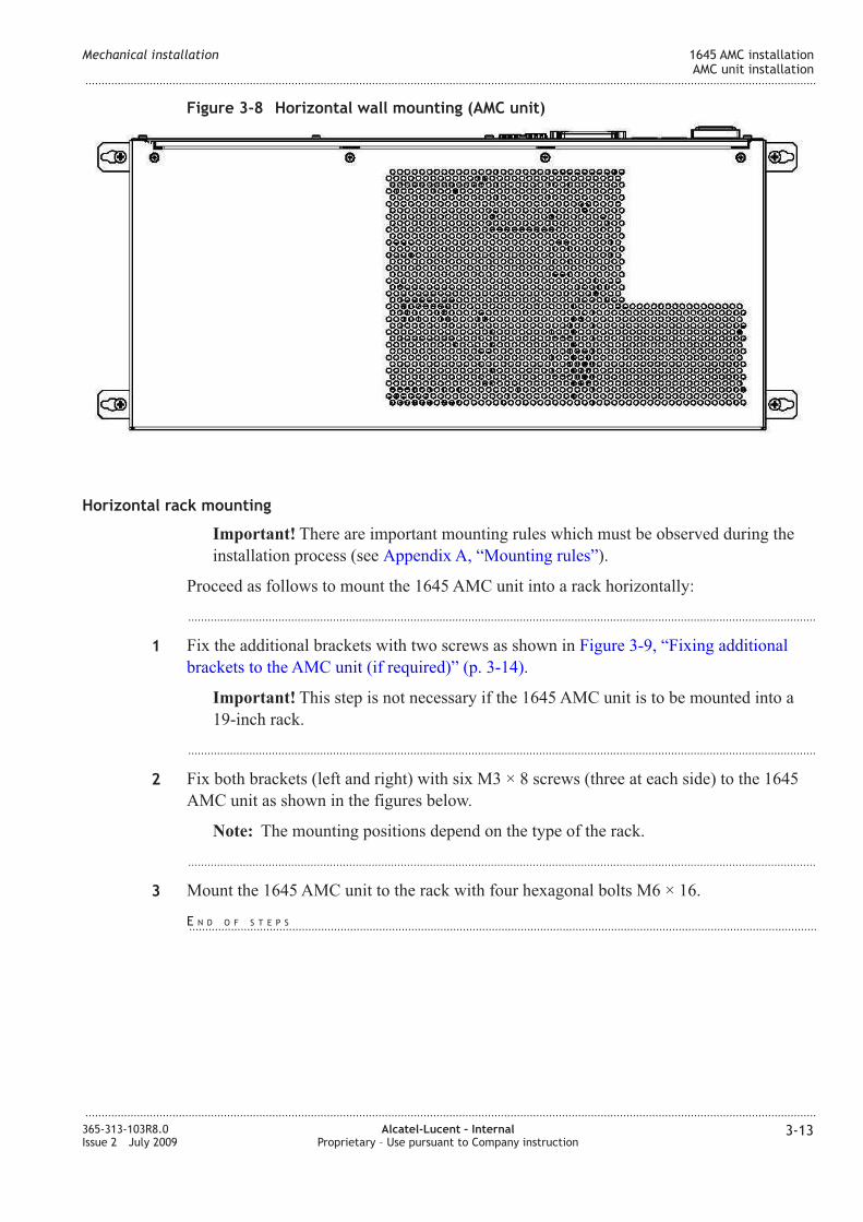
3-8 Horizontal wall mounting (AMC unit) ............................................................................................................ 3-133-13
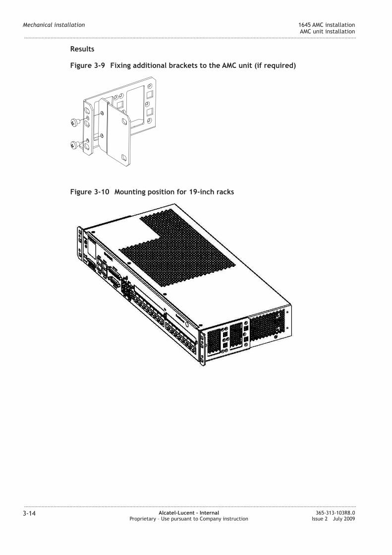
3-9 Fixing additional brackets to the AMC unit (if required) ......................................................................... 3-143-14
3-10 Mounting position for 19-inch racks ................................................................................................................ 3-143-14
3-11 Mounting position for ETSI-2 (LambdaUnite) racks (back-to-back, depth 600 mm) ................... 3-153-15
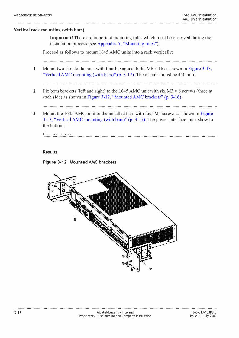
3-12 Mounted AMC brackets ........................................................................................................................................ 3-163-16
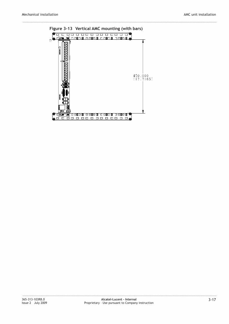
3-13 Vertical AMC mounting (with bars) ................................................................................................................. 3-173-17
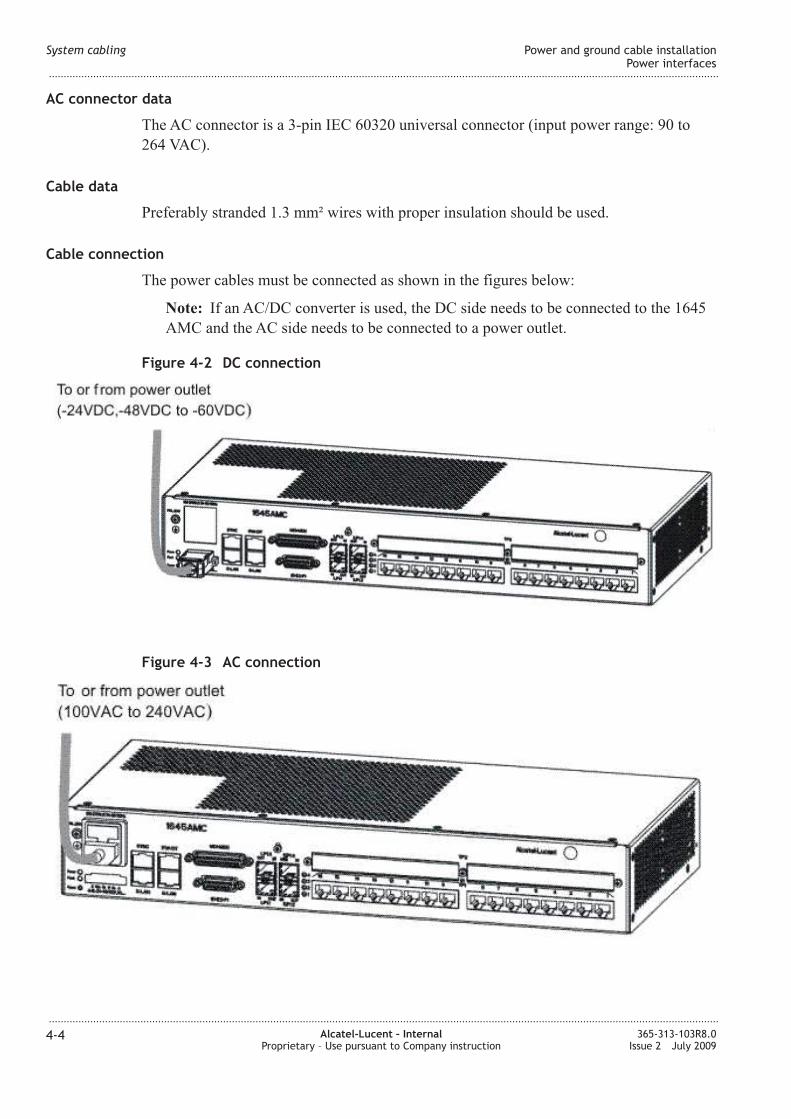
4-1 DC connector ............................................................................................................................................................. 4-34-3
4-2 DC connection ........................................................................................................................................................... 4-44-4
4-3 AC connection ........................................................................................................................................................... 4-44-4
4-4 Fan power connector ................................................................................................................................................ 4-74-7
...................................................................................................................................................................................................................................
365-313-103R8.0Issue 2 July 2009
Alcatel-Lucent – InternalProprietary – Use pursuant to Company instruction
xi
Page 12
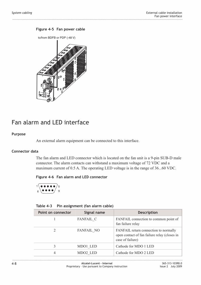
4-5 Fan power cable ......................................................................................................................................................... 4-84-8
4-6 Fan alarm and LED connector .............................................................................................................................. 4-84-8
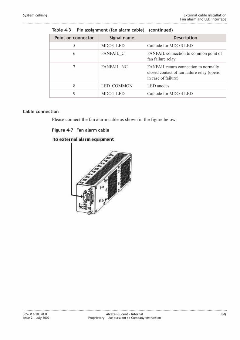
4-7 Fan alarm cable .......................................................................................................................................................... 4-94-9
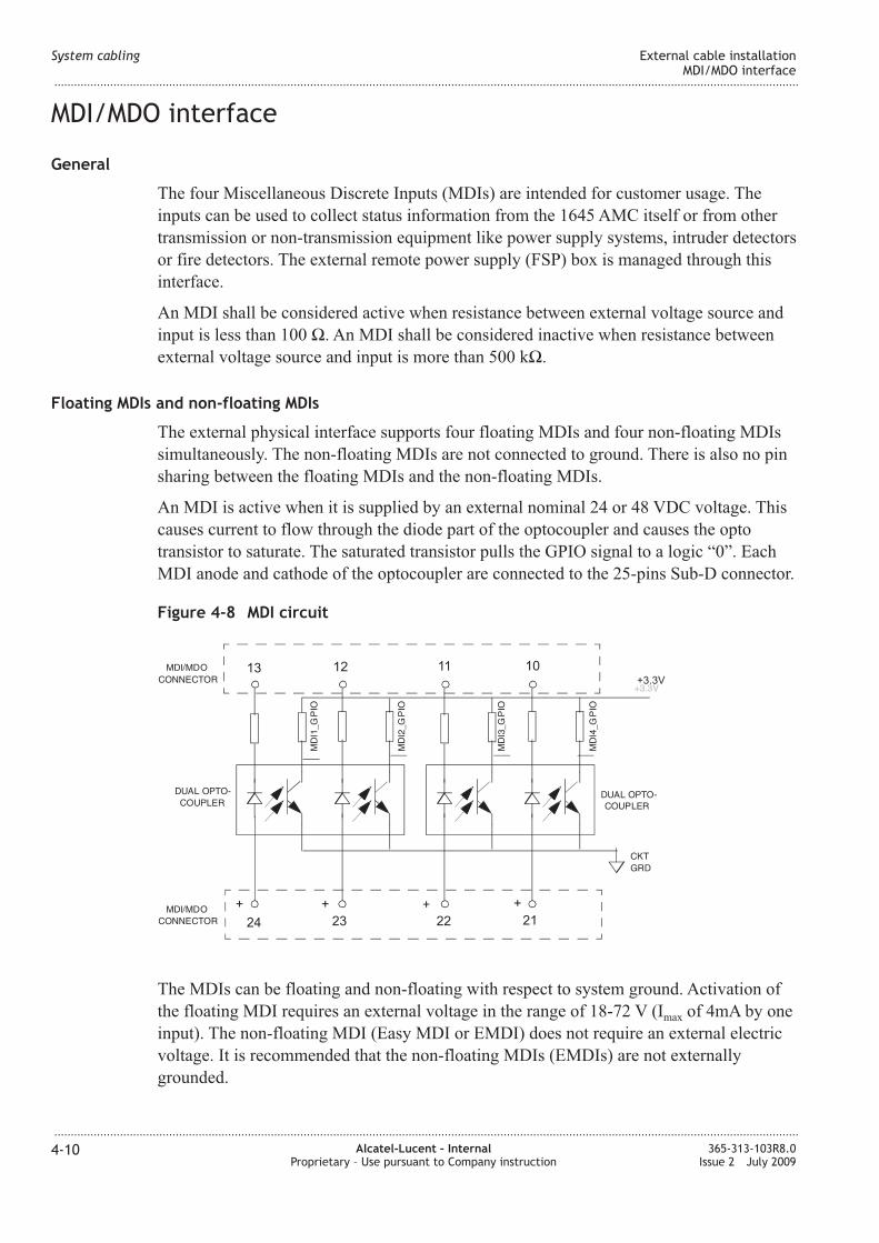
4-8 MDI circuit ................................................................................................................................................................ 4-104-10
4-9 MDI implementation .............................................................................................................................................. 4-114-11
4-10 MDO circuit .............................................................................................................................................................. 4-124-12
4-11 MDI/MDO connector ............................................................................................................................................ 4-124-12
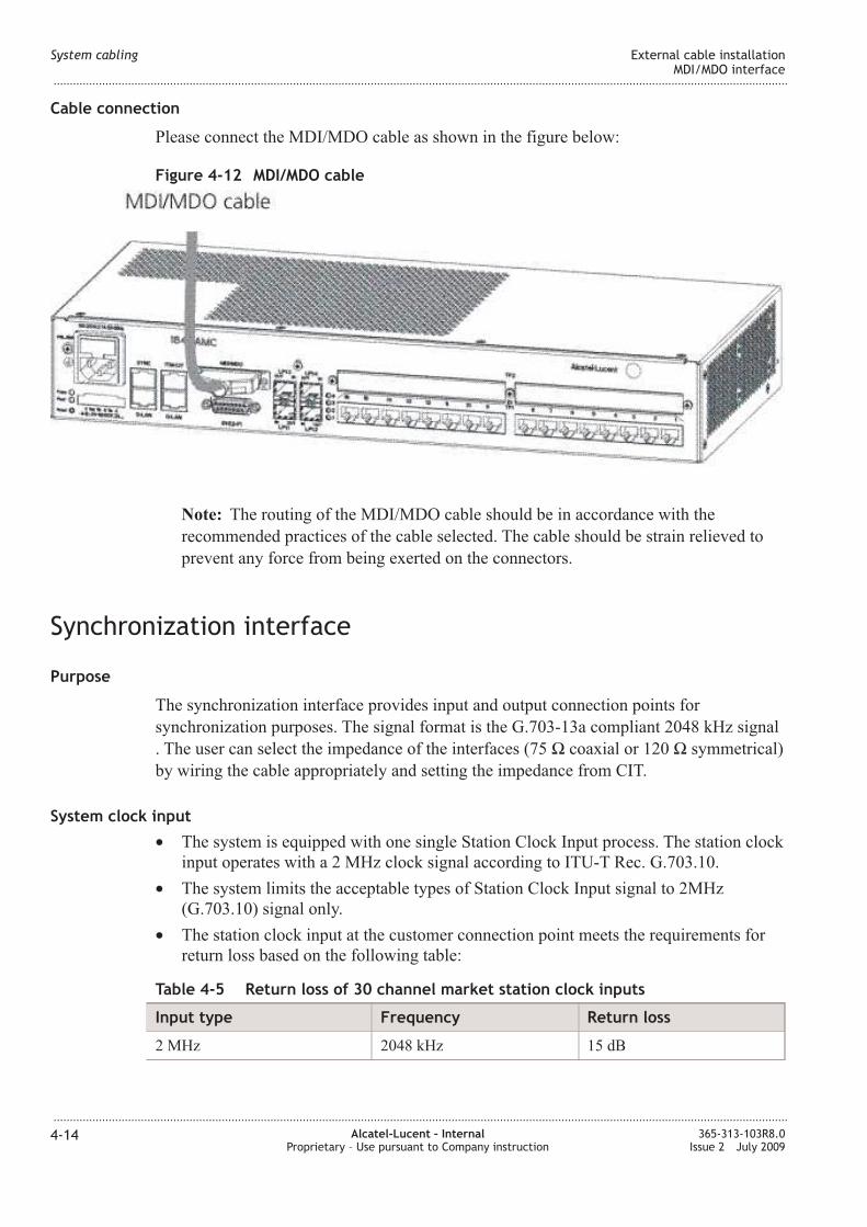
4-12 MDI/MDO cable .................................................................................................................................................... 4-144-14
4-13 Timing connector .................................................................................................................................................... 4-164-16
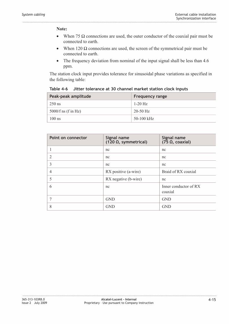
4-14 Timing cable ............................................................................................................................................................ 4-174-17
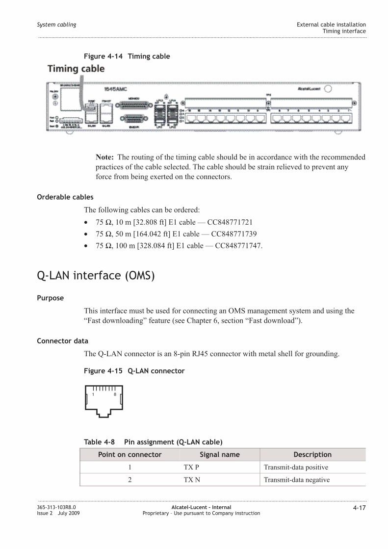
4-15 Q-LA connector ................................................................................................................................................... 4-174-17
4-16 Q-LA cable ............................................................................................................................................................ 4-184-18
4-17 ITM-CIT connector ................................................................................................................................................ 4-194-19
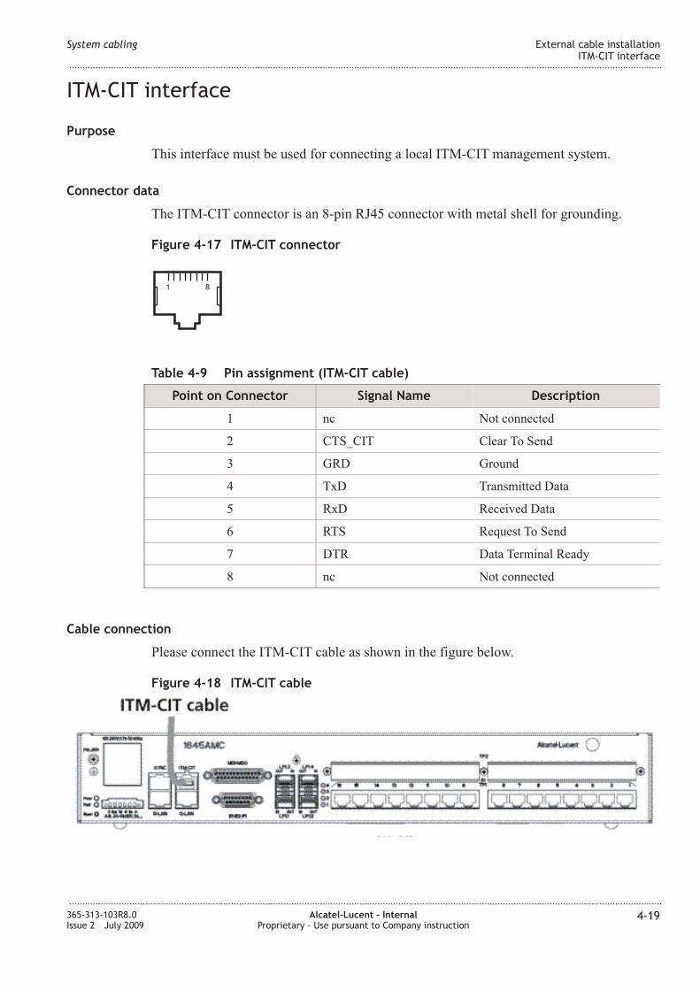
4-18 ITM-CIT cable ........................................................................................................................................................ 4-194-19
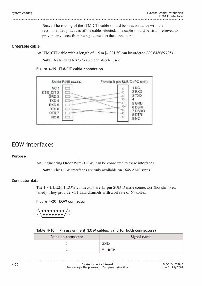
4-19 ITM-CIT cable connection .................................................................................................................................. 4-204-20
4-20 EOW connector ........................................................................................................................................................ 4-204-20
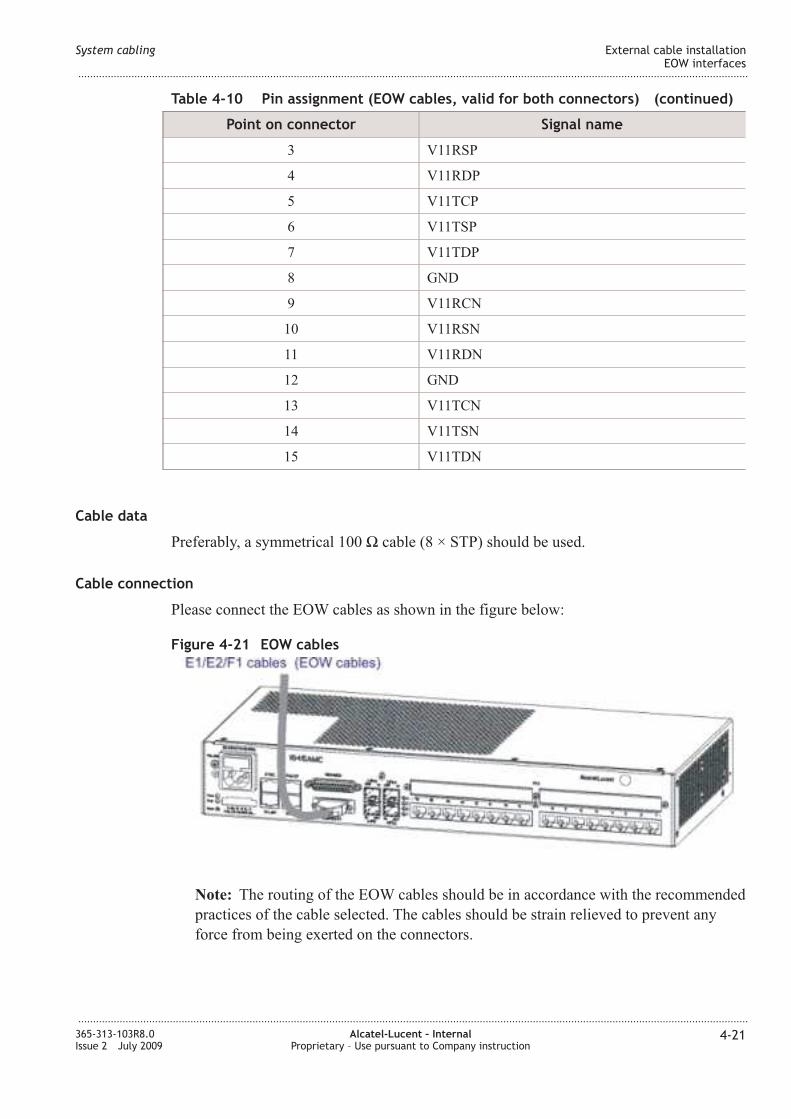
4-21 EOW cables ............................................................................................................................................................... 4-214-21
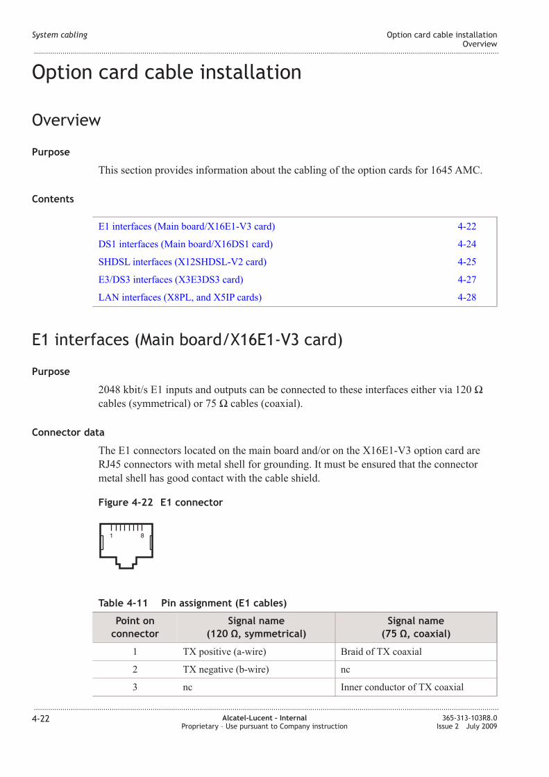
4-22 E1 connector ............................................................................................................................................................. 4-224-22
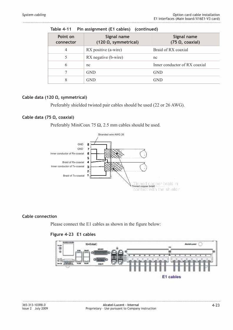
4-23 E1 cables .................................................................................................................................................................... 4-234-23
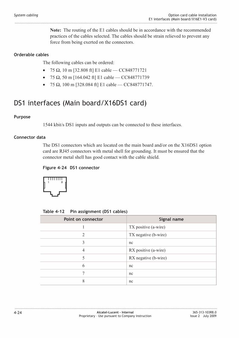
4-24 DS1 connector .......................................................................................................................................................... 4-244-24
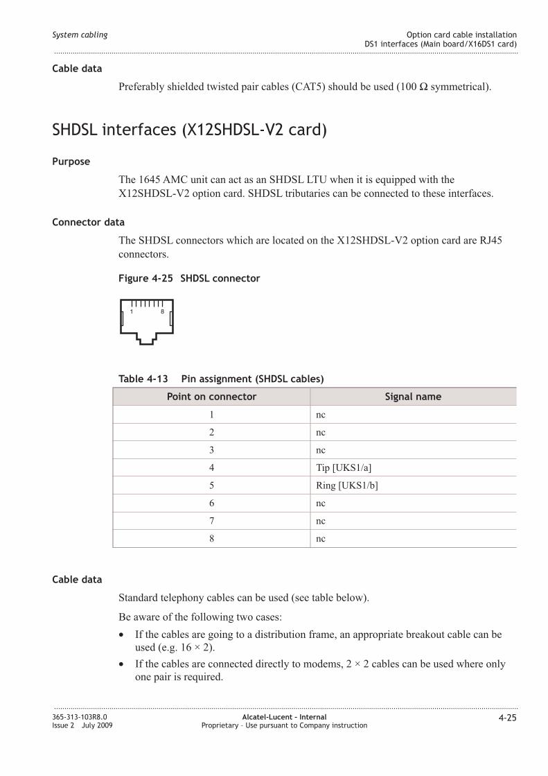
4-25 SHDSL connector ................................................................................................................................................... 4-254-25
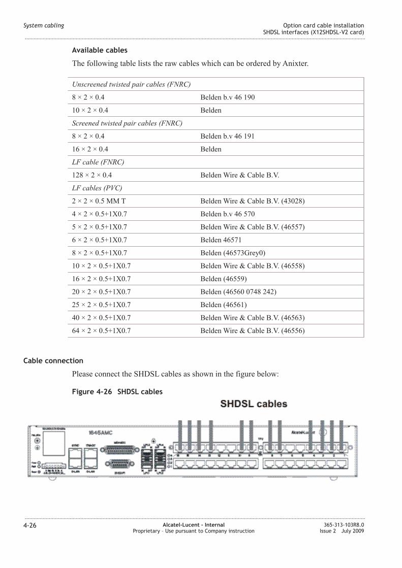
4-26 SHDSL cables .......................................................................................................................................................... 4-264-26
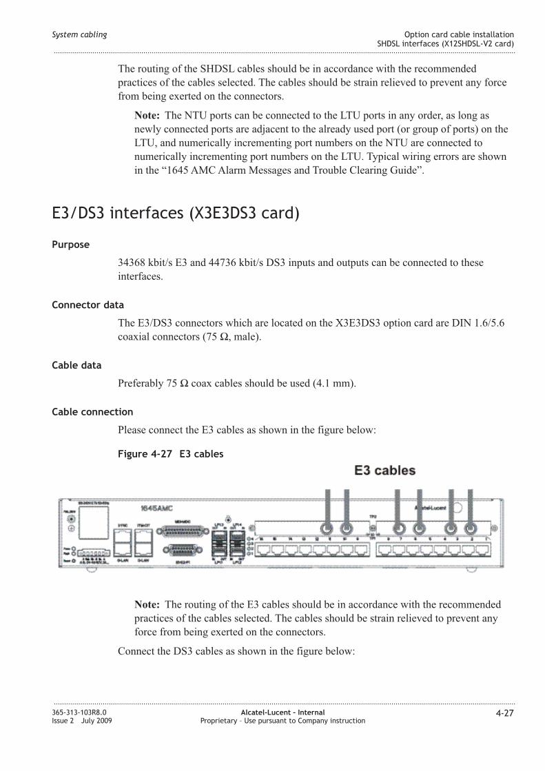
4-27 E3 cables .................................................................................................................................................................... 4-274-27
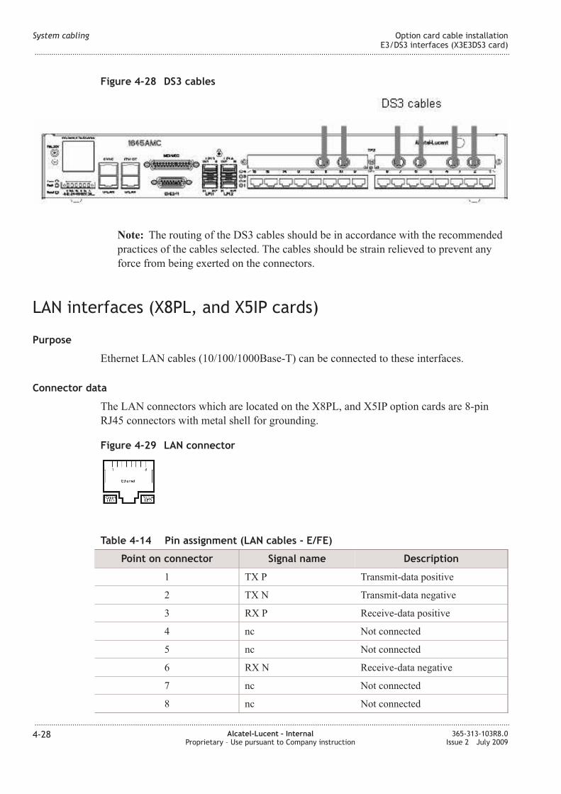
4-28 DS3 cables ................................................................................................................................................................. 4-284-28
4-29 LA connector ......................................................................................................................................................... 4-284-28
4-30 Cable design (LA cable - GE) ......................................................................................................................... 4-294-29
4-31 LA cables .............................................................................................................................................................. 4-304-30
4-32 Cable design (STM-1e cable) ............................................................................................................................. 4-334-33
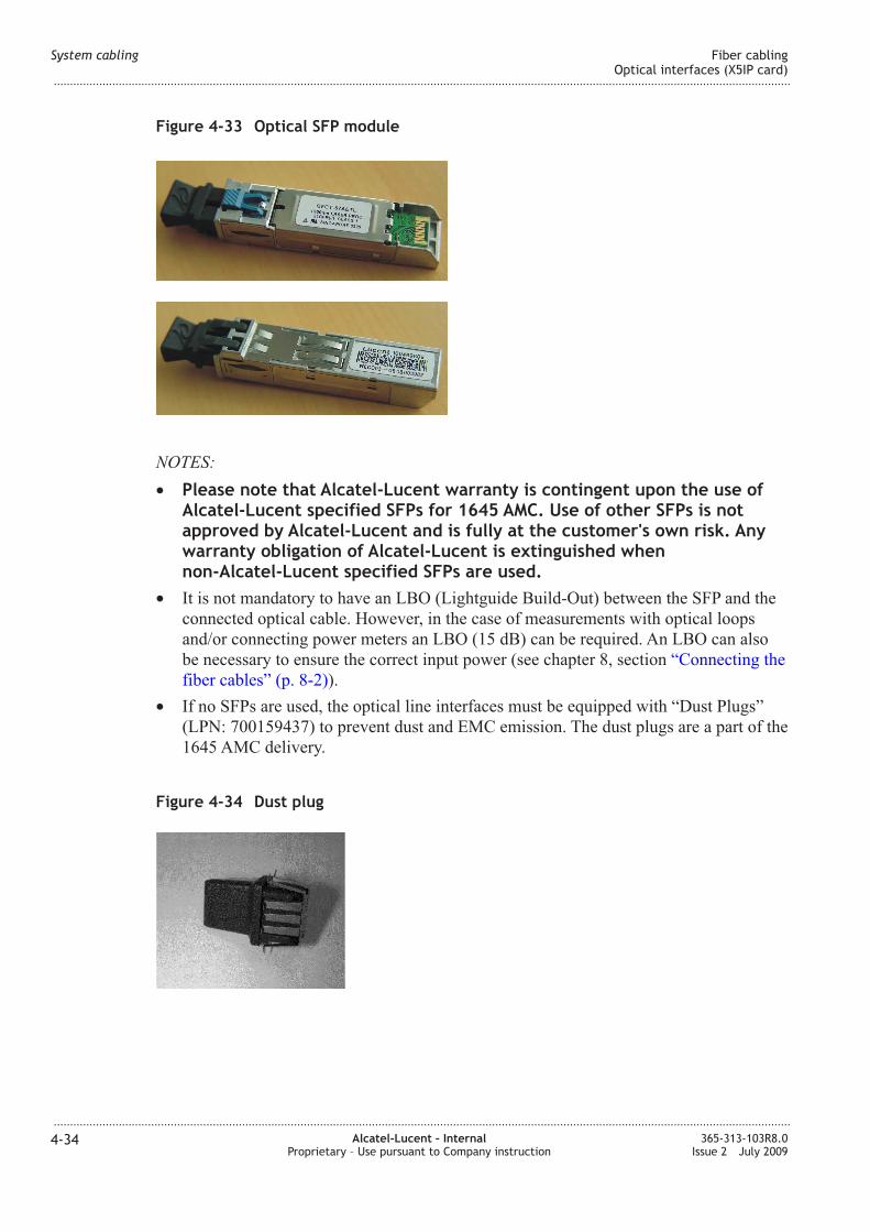
4-33 Optical SFP module ................................................................................................................................................ 4-344-34
List of figures
...................................................................................................................................................................................................................................
...................................................................................................................................................................................................................................
xii Alcatel-Lucent – InternalProprietary – Use pursuant to Company instruction
365-313-103R8.0Issue 2 July 2009
Page 13
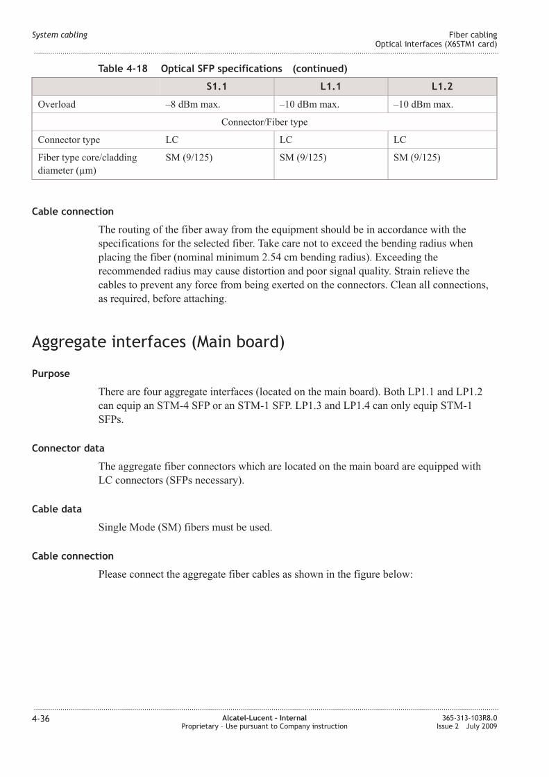
4-34 Dust plug .................................................................................................................................................................... 4-344-34
4-35 Aggregate fiber cables ......................................................................................................................................... 4-374-37
6-1 Connection with crossed Ethernet cable (AMC unit) .................................................................................. 6-86-8
6-2 Connection with crossed Ethernet cable (AMC unit) .................................................................................. 6-96-9
6-3 ITM-CIT cable connection (AMC unit) .......................................................................................................... 6-116-11
6-4 ITM-CIT cable connection (AMC unit) .......................................................................................................... 6-116-11
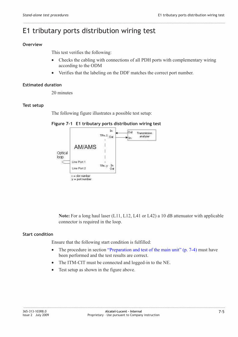
7-1 E1 tributary ports distribution wiring test ......................................................................................................... 7-57-5
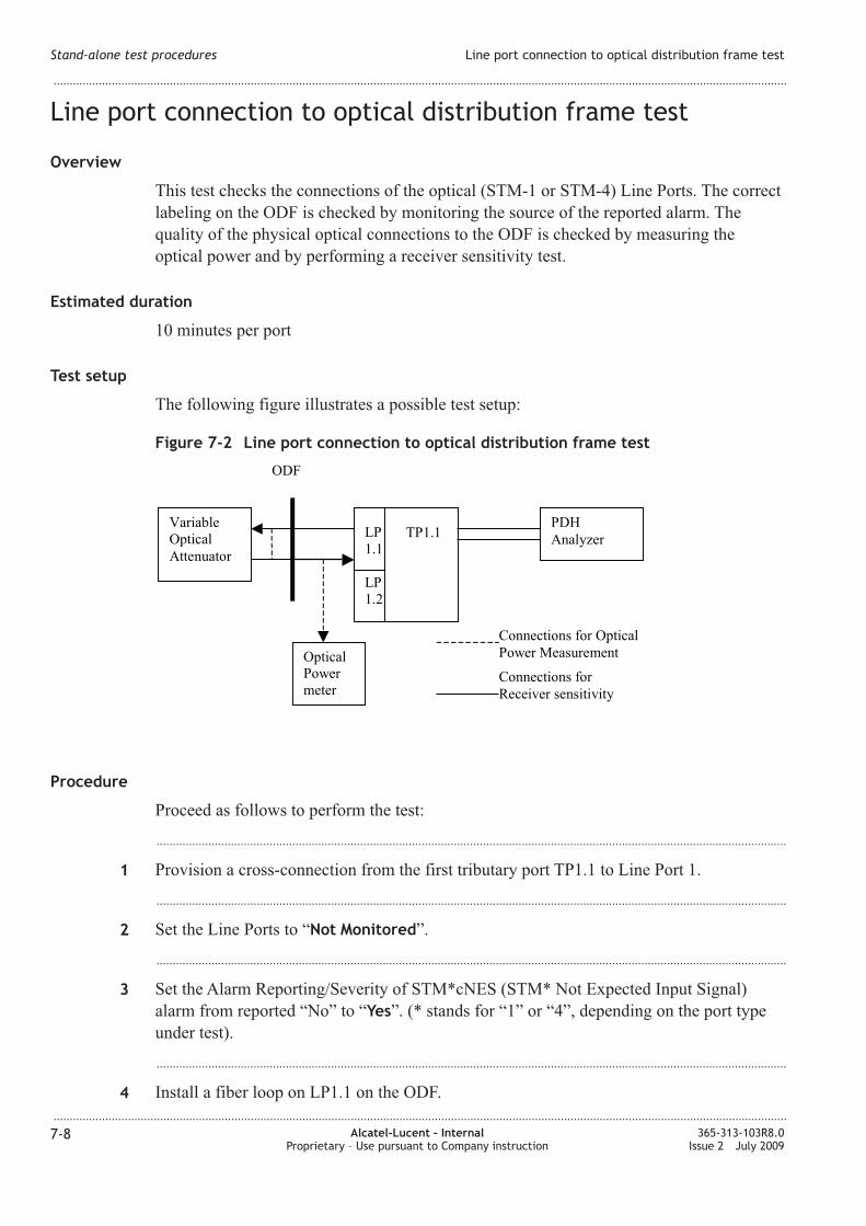
7-2 Line port connection to optical distribution frame test ................................................................................ 7-87-8
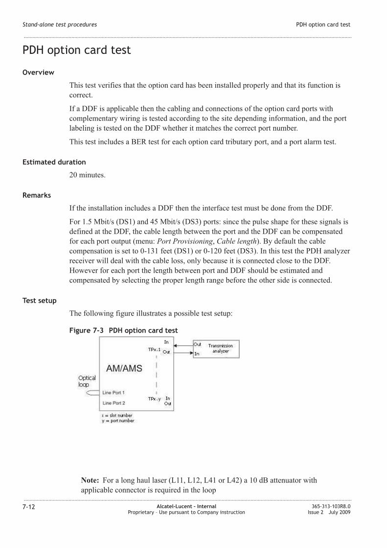
7-3 PDH option card test .............................................................................................................................................. 7-127-12
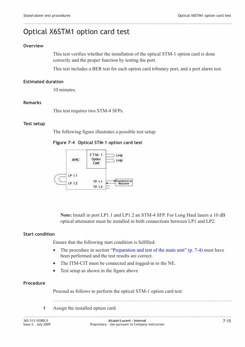
7-4 Optical STM-1 option card test .......................................................................................................................... 7-157-15
7-5 X12SHDSL-V2 option card test ........................................................................................................................ 7-217-21
8-1 Remote login test ....................................................................................................................................................... 8-48-4
8-2 BER test ........................................................................................................................................................................ 8-68-6
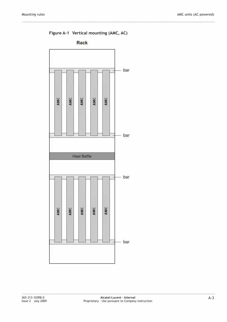
A-1 Vertical mounting (AMC, AC) ............................................................................................................................ A-3A-3
B-1 Unlocking a MSA latch (type 1) SFP .............................................................................................................. B-11B-11
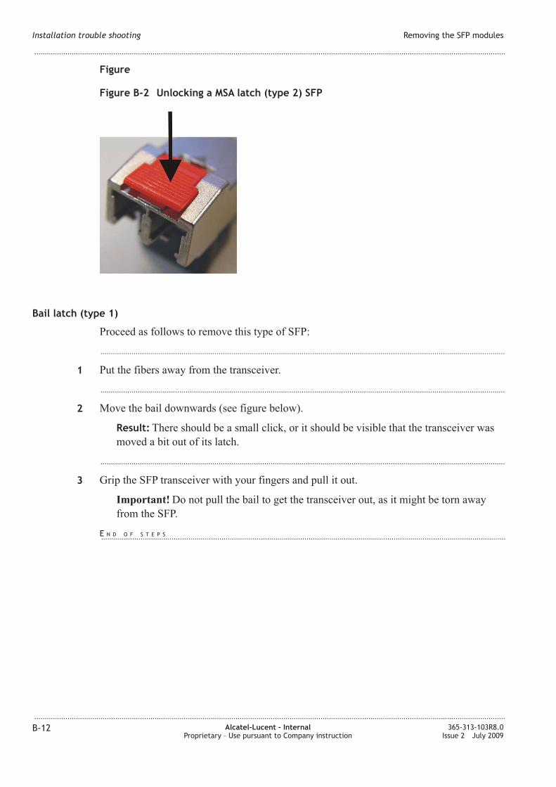
B-2 Unlocking a MSA latch (type 2) SFP ............................................................................................................. B-12B-12
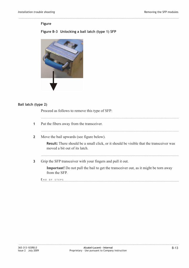
B-3 Unlocking a bail latch (type 1) SFP ................................................................................................................ B-13B-13
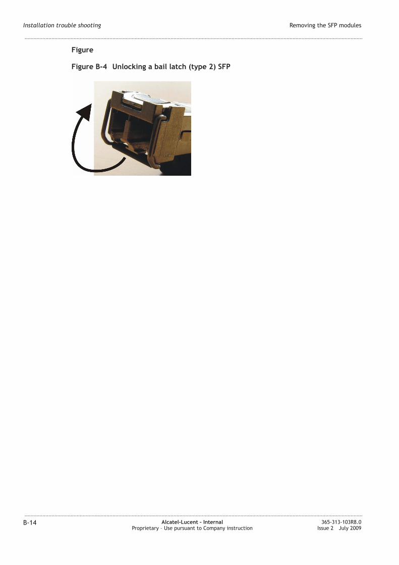
B-4 Unlocking a bail latch (type 2) SFP ................................................................................................................ B-14B-14
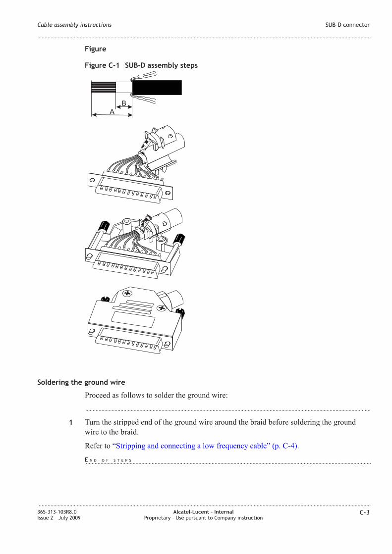
C-1 SUB-D assembly steps ........................................................................................................................................... C-3C-3
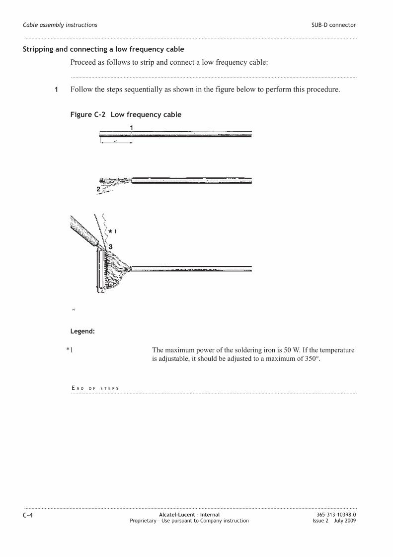
C-2 Low frequency cable ............................................................................................................................................... C-4C-4
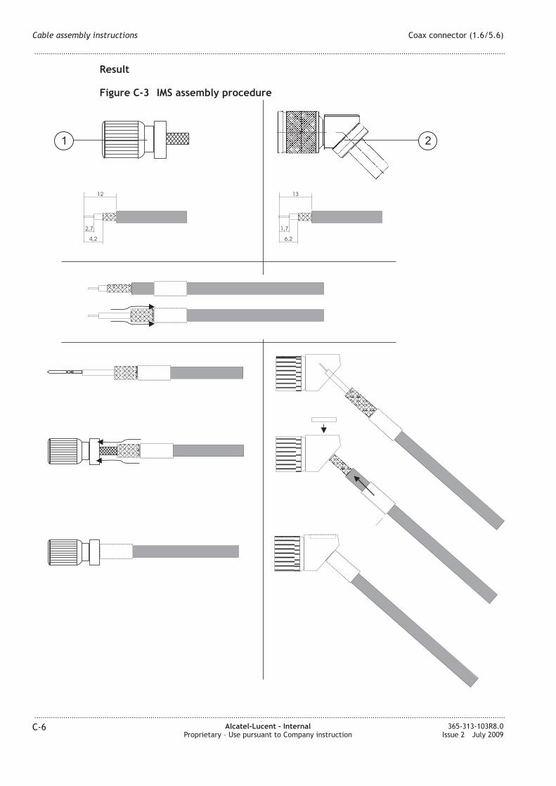
C-3 IMS assembly procedure ........................................................................................................................................ C-6C-6
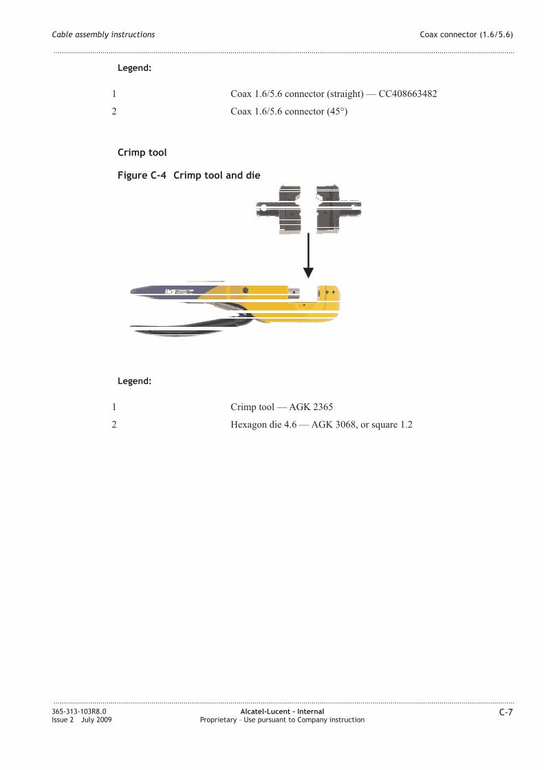
C-4 Crimp tool and die .................................................................................................................................................... C-7C-7
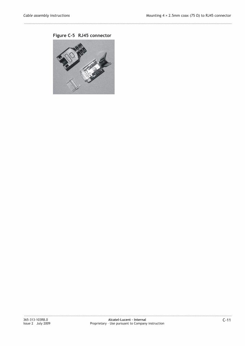
C-5 RJ45 connector ........................................................................................................................................................ C-11C-11
List of figures
...................................................................................................................................................................................................................................
...................................................................................................................................................................................................................................
365-313-103R8.0Issue 2 July 2009
Alcatel-Lucent – InternalProprietary – Use pursuant to Company instruction
xiii
Page 15
About this documentAbout this document
Purpose
This manual provides information on the installation and configuration of 1645 AMC
units. Furthermore, all steps for putting the system into operation are also described.
Safety information
For your safety, this document contains safety statements. Safety statements are given at
points where risks of damage to personnel, equipment, and operation may exist. Failure to
follow the directions in a safety statement may result in serious consequences.
Intended audience
This manual is intended for users who wish to install, configure and cable 1645 AMC
units including all accessories.
This requires that the installation staff has a basic knowledge of SDH and Ethernet
technology. Working on the equipment described in this manual requires also special
training of the personnel.
How to use this information product
This manual is divided into the following sections with a brief description of the contents
of each major part/chapter/appendix:
About this document describes the purpose, intended audience, reason for reissue, and
organization of this document. This section references related documentation and explains
how to order, make comments or recommend changes to this document.
Part I – Physical and power installation
• Chapter 1, Safety
This chapter provides all relevant information and safety guidelines to safeguard
against personal injury. Furthermore, this chapter may be useful to prevent material
damage to the equipment.
• Chapter 2, General information
This chapter provides all facts which must be known before the system can be
installed, such as environmental requirements, ITM-CIT requirements, EMC/ESD
information, etc.
• Chapter 3, Mechanical installation
This chapter provides all information needed to install 1645 AMC units....................................................................................................................................................................................................................................
365-313-103R8.0Issue 2 July 2009
Alcatel-Lucent – InternalProprietary – Use pursuant to Company instruction
xv
Page 16
• Chapter 4, System cabling
This chapter provides all tasks for a complete system cabling.
• Chapter 5, Powering
This chapter describes the system powering and some final tests which should be
performed to end the physical installation part.
Part II – NE provisioning and stand alone installation test
• Chapter 6, ITM-CIT installation and E provisioning
This chapter describes the ITM-CIT and E software installation and the initial E
provisioning via ITM-CIT.
• Chapter 7, Stand alone test procedures
This chapter provides all tests which must be performed to verify the proper working
of the units/Es.
Part III – Link testing
• Chapter 8, Link testing
This chapter provides link acceptance tests which are necessary to verify the
functionality of the overall system.
• Chapter 9, Conclusion
This chapter provides a final checklist and a signoff sheet to be sure that all required
tasks described in this manual have been done.
Appendices
• Appendix A, Mounting rules
This chapter provides rules which have to be observed during physical installation.
• Appendix B, Installation Troubleshooting
This chapter provides basic installation troubleshooting information.
• Appendix C, Cable assembly instructions
This chapter provides general cable assembly instructions.
Glossary provides definitions for telecommunication acronyms and terms.
Index supplies users with specific subjects and corresponding page numbers to find
necessary information.
Conventions used
The following conventions are used throughout the manual:
Numbering
The chapters of this document are numbered consecutively. The page numbering restarts
at “1” in each chapter. To facilitate identifying pages in different chapters, the page
numbers are prefixed with the chapter number. For example, page 2-3 is the third page in
chapter 2.
Cross-references
Cross-reference conventions are identical with those used for numbering, i.e. the first
number in a reference to a particular page refers to the corresponding chapter.
About this document
...................................................................................................................................................................................................................................
...................................................................................................................................................................................................................................
xvi Alcatel-Lucent – InternalProprietary – Use pursuant to Company instruction
365-313-103R8.0Issue 2 July 2009
Page 17
Keyword-blocks
This document contains so-called keyword blocks to facilitate the location of specific text
passages. The keyword blocks are placed to the left of the main text and indicate the
contents of a paragraph or group of paragraphs.
Abbreviations
Abbreviations used in this document can be found in the “Glossary” unless it can be
assumed that the reader is familiar with the abbreviation.
Codes
The codes (CC, DC and SC) in this manual are used to define a hardware item owned by
the Alcatel-Lucent Development Systems. The code consists of a letter combination
followed by a combination of numbers (Example: CC123456789).
Related documentation
This section briefly describes the documents that are included in the 1645 AMC
documentation set.
• Installation GuideThe 1645 AMC Installation Guide is a step-by-step guide to system installation and
setup. It also includes information needed for pre-installation site planning and
post-installation acceptance testing.
• Applications and Planning GuideThe 1645 AMCApplications and Planning Guide (APG) is for use by network
planners, analysts and managers. It is also for use by the Alcatel-Lucent Account
Team. It presents a detailed overview of the system, describes its applications, gives
planning requirements, engineering rules, ordering information, and technical
specifications.
• User Operations GuideThe 1645 AMC User Operations Guide provides step-by-step information for use in
daily system operations. The manual demonstrates how to perform system
provisioning, operations, and administrative tasks by use of ITM-CIT.
• Alarm Messages and Trouble Clearing GuideThe 1645 AMCAlarm Messages and Trouble Clearing Guide gives detailed
information on each possible alarm message. Furthermore, it provides procedures for
routine maintenance, troubleshooting, diagnostics, and component replacement.
• OMS Provisioning Guide (Application 1645 AMC)The OMS Provisioning Guide gives instructions on how to perform system
provisioning, operations, and administrative tasks by use of OMS.
The following table lists the documents included in the 1645 AMC documentation set.
Document title Document code
1645 AMCApplications and Planning Guide 109642330
(365-313-102R8.0)
About this document
...................................................................................................................................................................................................................................
...................................................................................................................................................................................................................................
365-313-103R8.0Issue 2 July 2009
Alcatel-Lucent – InternalProprietary – Use pursuant to Company instruction
xvii
Page 18
Document title Document code
1645 AMC User Operations Guide 109642272
(365-313-104R8.0)
1645 AMCAlarm Messages and Trouble Clearing Guide 109642322
(365-313-105R8.0)
1645 AMC Installation Guide 109642231
(365-313-103R8.0
1350 OMS Provisioning Guide (Application 1645 AMC ) 109642249
(365-313-106R8.0)
CD-ROM Documentation 1645 AMC (all manuals on a CD-ROM) 109642215
(365-313-107R8.0)
Technical support
Alcatel-Lucent provides the following Technical Support Services:
• Remote Technical Support (RTS) – remote technical support to troubleshoot and
resolve system problems.
• On-site Technical Support (OTS) – on-site assistance with operational issues and
remedial maintenance.
• Repair and Replacement (R&R) – technical support services for device repair/return
or parts replacement.
• Alcatel-Lucent Online Customer Support – online access to information and services
that can help resolve technical support requests.
ote: Technical Support Services are available 24 hours a day, 7 days a week.
When additional technical assistance is needed, use the appropriate contact
information in the table below:
Customer location Initial Alcatel-Lucent contact location
Inside the United States and
Canada
Technical Support Services can be reached at
0 866-582-3688 Prompt#1.
Outside the United States Technical Support Services can be reached at
+1-630-224-4672: Prompt#2.
Web Site For additional information regarding Worldwide Services, refer
to the Alcatel-Lucent web site at
http://www.alcatel-lucent.com/solutions/lws.html
About this document
...................................................................................................................................................................................................................................
...................................................................................................................................................................................................................................
xviii Alcatel-Lucent – InternalProprietary – Use pursuant to Company instruction
365-313-103R8.0Issue 2 July 2009
Page 19
How to order
For all questions concerning ordering of 1645 AMC documentation, for a complete list of
the marketable items and their comcodes, and for ordering the equipment please contact
your Account Executive or your Alcatel-Lucent local customer team.
How to comment
Because customer satisfaction is extremely important to Alcatel-Lucent, every attempt is
made to encourage feedback from customers about our information products. Thank you
for your feedback.
About this document
...................................................................................................................................................................................................................................
...................................................................................................................................................................................................................................
365-313-103R8.0Issue 2 July 2009
Alcatel-Lucent – InternalProprietary – Use pursuant to Company instruction
xix
Page 21
Part I: Physical and power
installation
Overview
Purpose
This part of the 1645 AMC Installation Guide contains the physical installation of the
1645 AMC units including the system cabling and the system powering.
Contents
This part of the document contains the following chapters:
• Chapter 1
Safety
• Chapter 2
General information
• Chapter 3
Mechanical installation
• Chapter 4
System cabling
• Chapter 5
Powering.
Entry checklist
The following table provides a checklist to be completed prior to performing the physical
and power installation. Verify that each procedure has been completed. Check off and
initial the item.
Procedure Completed Initials Notes
Are the needed 1645 AMC units available?
Are all needed option cards available?
Is a fan unit available (if required)?
Is an AC/DC converter available (if required)?
Are all needed SFPs available?
Is the EMC bracket available?
...................................................................................................................................................................................................................................
365-313-103R8.0Issue 2 July 2009
Alcatel-Lucent – InternalProprietary – Use pursuant to Company instruction
I-1
Page 22
Procedure Completed Initials Notes
Are all needed cables available?
Are there any obstacles that will affect the physical
installation or cabling?
Are the required fuse/breaker positions available?
Is an ESD wrist strap available?
Aremetric tools available?
Is a torque wrench available?
Is a soldering iron available?
Are the needed crimping tools available?
Is a multimeter available?
Is an ohmmeter available?
Contents
Chapter 1, Safety 1-1
Chapter 2, General information 2-1
Chapter 3, Mechanical installation 3-1
Chapter 4, System cabling 4-1
Chapter 5, Powering 5-1
Physical and power installation Overview
...................................................................................................................................................................................................................................
...................................................................................................................................................................................................................................
I-2 Alcatel-Lucent – InternalProprietary – Use pursuant to Company instruction
365-313-103R8.0Issue 2 July 2009
Page 23
1 1Safety
Overview
Purpose
The aim of this chapter on safety is to provide users of 1645 AMC system with the
relevant information and safety guidelines to safeguard against personal injury.
Furthermore, this chapter may be useful to prevent material damage to the equipment.
The present chapter on safety must be read by the responsible technical personnel before
carrying out relevant work on the system. The valid version of this document must always
be kept close to the equipment.
Potential sources of danger
The 1645 AMC system has been developed in line with the present state-of-the-art and
fulfils the current national and international safety requirements. They are provided with a
high degree of operational safety resulting from many years of development experience
and continuous stringent quality checks in our company.
The equipment is safe in normal operation. There are, however, some potential sources of
danger that cannot be completely eliminated. In particular, these arise during the:
• opening of housings or equipment covers
• manipulation of any kind within the equipment, even if it has been disconnected from
the power supply
• disconnection of optical or electrical connection
• installation or removal of SFPs
through possible contact with the following:
• live parts
• laser light
• hot surfaces, or
• sharp edges
Contents
General notes on safety 1-3
...................................................................................................................................................................................................................................
365-313-103R8.0Issue 2 July 2009
Alcatel-Lucent – InternalProprietary – Use pursuant to Company instruction
1-1
Page 24
Structure of safety statements 1-3
Basic safety aspects 1-6
Specific safety areas 1-8
Laser safety 1-8
Optical circuit pack specifications 1-11
Power supply safety instructions 1-11
Electrostatic discharge 1-12
Conformity statements 1-13
Safety Overview
...................................................................................................................................................................................................................................
...................................................................................................................................................................................................................................
1-2 Alcatel-Lucent – InternalProprietary – Use pursuant to Company instruction
365-313-103R8.0Issue 2 July 2009
Page 25
General notes on safety
Overview
Purpose
This section provides general information on the structure of safety instructions and
summarizes general safety requirements.
Contents
Structure of safety statements 1-3
Basic safety aspects 1-6
Structure of safety statements
Overview
Safety statements describe the safety risks relevant while performing tasks on
Alcatel-Lucent products during deployment and/or use. Failure to avoid the hazards may
have serious consequences.
General structure
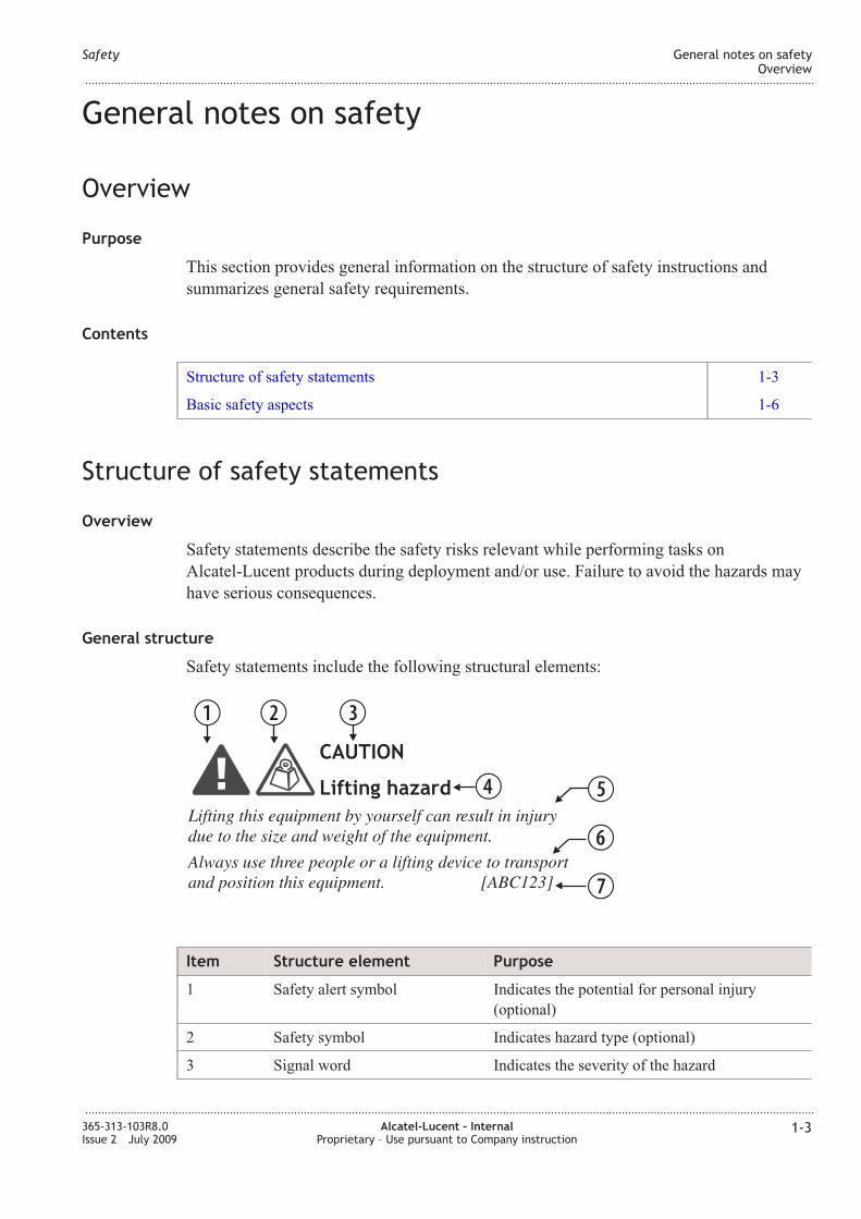
Safety statements include the following structural elements:
Item Structure element Purpose
1 Safety alert symbol Indicates the potential for personal injury
(optional)
2 Safety symbol Indicates hazard type (optional)
3 Signal word Indicates the severity of the hazard
Lifting this equipment by yourself can result in injury
due to the size and weight of the equipment.
Always use three people or a lifting device to transport
and position this equipment. [ABC123]
CAUTION
Lifting hazard
B C D
E F
G
H
Safety General notes on safetyOverview
...................................................................................................................................................................................................................................
...................................................................................................................................................................................................................................
365-313-103R8.0Issue 2 July 2009
Alcatel-Lucent – InternalProprietary – Use pursuant to Company instruction
1-3
Page 26
Item Structure element Purpose
4 Hazard type Describes the source of the risk of damage or
injury
5 Safety message Consequences if protective measures fail
6 Avoidance message Protective measures to take to avoid the hazard
7 Identifier The reference ID of the safety statement
(optional)
Signal words
The signal words identify the hazard severity levels as follows:
Signal word Meaning
DAGER Indicates an extremely hazardous situation which, if not avoided, will
result in death or serious injury.
WARIG Indicates a hazardous situation which, if not avoided, could result in
death or serious injury.
CAUTIO Indicates a hazardous situation which, if not avoided, could result in
minor or moderate injury.
OTICE Indicates a hazardous situation not related to personal injury.
Warning symbols
These warning symbols are defined for safety instructions:
Safety General notes on safetyStructure of safety statements
...................................................................................................................................................................................................................................
...................................................................................................................................................................................................................................
1-4 Alcatel-Lucent – InternalProprietary – Use pursuant to Company instruction
365-313-103R8.0Issue 2 July 2009
Page 27
Legend:
1 General warning of danger
2 Electric shock
3 Hazard of laser radiation
4 Components sensitive to electrostatic discharge (ESD)
5 Electromagnetic radiation
6 Flammable material/Risk of fire
7 Service disruption hazard
8 Laceration hazard
9 Corrosive substance
10 Hazard caused by batteries
11 Hot surface
12 Heavy overload load
13 oxious substance
14 Explosion hazard
Safety General notes on safetyStructure of safety statements
...................................................................................................................................................................................................................................
...................................................................................................................................................................................................................................
365-313-103R8.0Issue 2 July 2009
Alcatel-Lucent – InternalProprietary – Use pursuant to Company instruction
1-5
Page 28
15 Falling object hazard
16 Risk of suffocation
17 Pinch hazard
18 Lifting hazard, heavy object
19 Inhalation hazard
20 Slip hazard
21 Trip hazard
22 Hazard of falling
Basic safety aspects
General safety requirements
In order to keep the technically unavoidable residual risk to a minimum, it is imperative
to observe the following rules:
• Transport, storage and operation of the system must be under the permissible
conditions only.
See accompanying documentation and information on the system.
• Installation, configuration and disassembly must be carried out only by expert
personnel and with reference to the respective documentation.
Due to the complexity of the system, the personnel requires special training.
• The system must be operated by expert and authorized users only.
The user must operate the system only after having read and understood this chapter
on safety and the parts of the documentation relevant to operation. For complex
systems, additional training is recommended. Any obligatory training for operating
and service personnel must be carried out and documented.
• The system must not be operated unless it is in perfect working order.
Any faults and errors that might affect safety must be reported immediately by the
user to a person in responsibility.
• The system must be operated only with the connections and under the environmental
conditions as described in the documentation.
• Any conversions or changes to the system or parts of the system (including the
software) must be carried out by qualified Alcatel-Lucent personnel or by expert
personnel authorized by Alcatel-Lucent.
All changes carried out by other persons lead to a complete exemption from liability.
o components/spare parts must be used other than those recommended by the
manufacturer and those listed in the procurement documents.
Safety General notes on safetyStructure of safety statements
...................................................................................................................................................................................................................................
...................................................................................................................................................................................................................................
1-6 Alcatel-Lucent – InternalProprietary – Use pursuant to Company instruction
365-313-103R8.0Issue 2 July 2009
Page 29
• The removal or disabling of safety facilities, the clearing of faults and errors, and the
maintenance of the equipment must be carried out by specially qualified personnel
only.
The respective parts of the documentation must be strictly observed. The
documentation must also be consulted during the selection of measuring and test
equipment.
• Calibrations, special tests after repairs and regular safety checks must be carried out,
documented and archived.
• on-system software is used at one’s own risk. The use/installation of non-system
software can adversely affect the normal functioning of the system.
• Only use tested and virus-free data carriers (floppy disks, streamer tapes, …).
Safety General notes on safetyBasic safety aspects
...................................................................................................................................................................................................................................
...................................................................................................................................................................................................................................
365-313-103R8.0Issue 2 July 2009
Alcatel-Lucent – InternalProprietary – Use pursuant to Company instruction
1-7
Page 30
Specific safety areas
Overview
Purpose
The aspects of “laser safety” and “handling of components sensitive to electrostatic
discharge (ESD)” are of vital importance for the 1645 AMC equipment. Therefore, the
key safety instructions for these subjects are summarized in the following.
Contents
Laser safety 1-8
Optical circuit pack specifications 1-11
Power supply safety instructions 1-11
Electrostatic discharge 1-12
Conformity statements 1-13
Laser safety
Overview
Optical fiber telecommunication systems, their associated test sets, and similar operating
systems use semiconductor laser transmitters that emit infrared (IR) light at wavelengths
between approximately 800 nanometers and 1600 nanometers. The emitted light is above
the red end of the visible spectrum, which is normally not visible to the human eye.
Although radiant energy at near-IR wavelengths is officially designated invisible, some
people can see the shorter wavelength energy even at power levels several orders of
magnitude below any that have been shown to cause injury to the eye.
Conventional lasers can produce an intense beam of monochromatic light. The term
monochromaticity means a single wavelength output of pure color that may be visible or
invisible to the eye. A conventional laser produces a small-size beam of light, and because
the beam size is small the power density (also called irradiance) is very high.
Consequently, lasers and laser products are subject to federal and applicable state
regulations as well as international standards for their safe operation.
A conventional laser beam expands very little over distance, or is said to be very well
collimated. Thus, conventional laser irradiance remains relatively constant over distance.
However, lasers used in lightwave systems have a large beam divergence, typically 10 to
20 degrees. Here, irradiance obeys the inverse square law (doubling the distance reduces
the irradiance by a factor of 4) and rapidly decreases over distance.
Safety Specific safety areasOverview
...................................................................................................................................................................................................................................
...................................................................................................................................................................................................................................
1-8 Alcatel-Lucent – InternalProprietary – Use pursuant to Company instruction
365-313-103R8.0Issue 2 July 2009
Page 31
Lasers and eye damage
The optical energy emitted by laser and high-radiance LEDs in the 400-1400 nm range
may cause eye damage if absorbed by the retina. When a beam of light enters the eye, the
eye magnifies and focuses the energy on the retina magnifying the irradiance. The
irradiance of the energy that reaches the retina is approximately 105 or 100,000 times
more than at the cornea and, if sufficiently intense, may cause a retinal burn.
The damage mechanism at the wavelengths used in an optical fiber telecommunications is
thermal in origin i.e., damage caused by heating. Therefore, a specific amount of energy
is required for a definite time to heat an area of retinal tissue. Damage to the retina occurs
only when one looks at the light sufficiently long that the product of the retinal irradiance
and the viewing time exceeds the damage threshold. Optical energies above 1400 nm
cause corneal and skin burns but do not affect the retina. The thresholds for injury at
wavelengths greater than 1400 nm are significantly higher than for wavelengths in the
retinal hazard region.
Classification of lasers
Manufacturers of lasers and laser products in the U.S. are regulated by the Food and Drug
Administration's Center for Devices and Radiological Health (FDA/CDRH) under 21
CFR 1040. These regulations require manufacturers to certify each laser or laser product
as belonging to one of four major Classes I, II, lla, IlIa, lllb, or IV. The International
Electro-technical Commission is an international standards body that writes laser safety
standards under IEC-60825. Classification schemes are similar with Classes divided into
Classes 1, 1M, 2, 2M, 3B, 3R and 4. Lasers are classified according to the accessible
emission limits and their potential for causing injury. Optical fiber telecommunication
systems are generally classified as Class I/1, because, under normal operating conditions,
all energized laser transmitting circuit packs are terminated on optical fibers which
enclose the laser energy with the fiber sheath forming a protective housing. Also, a
protective housing / access panel is typically installed in front of the laser circuit pack
shelves. The circuit packs themselves, however, may be FDA/CDRH Class I or IIIb or
IEC Class 1, 1M, 3B, 3R or 4. State of the art Raman and EDFA optical amplifiers have
now extended into the Class IV/4 designations.
Lightwave safety precautions for optical fiber telecommunication systems
In its normal operating mode, an optical fiber telecommunication system is totally
enclosed and presents no risk of eye injury. It is a Class I/1 system under the FDA and
IEC classifications.
The fiber optic cables that interconnect various components of an optical fiber
telecommunication system can disconnect or break, and may expose people to laser
emissions. Also, certain measures and maintenance procedures may expose the technician
to emission from the semiconductor laser during installation and servicing. Unlike more
familiar laser devices, such as solid-state and gas lasers, the emission pattern of a
semiconductor laser results in a highly divergent beam. In a divergent beam, the
irradiance (power density) decreases rapidly with distance. The greater the distance, the
less energy will enter the eye, and the less potential risk for eye injury. Inadvertently
Safety Specific safety areasLaser safety
...................................................................................................................................................................................................................................
...................................................................................................................................................................................................................................
365-313-103R8.0Issue 2 July 2009
Alcatel-Lucent – InternalProprietary – Use pursuant to Company instruction
1-9
Page 32
viewing an unterminated fiber or damaged fiber with the unaided eye at distances greater
than 5 to 6 inches normally will not cause eye injury provided the power in the fiber is
less than a few milliwatts at the near IR wavelengths and a few tens of milliwatts at the
far IR wavelengths. However, damage may occur if an optical instrument such as a
microscope, magnifying glass or eye loupe is used to stare at the energized fiber end.
Important!Use of controls, adjustments and procedures other than those specified
herein may result in hazardous laser radiation exposure.
Laser safety precautions for enclosed systems
Under normal operating conditions, optical fiber telecommunication systems are
completely enclosed; nonetheless, the following precautions shall be observed:
1. Because of the potential for eye damage, technicians should not stare into optical
connectors or broken fibers.
2. Under no circumstance shall laser/fiber optic operations be performed by a technician
before satisfactorily completing training in laser safety.
3. Since viewing laser emissions directly in excess of Class I/1 limits with an optical
instrument such as an eye loupe greatly increases the risk of eye damage.
Laser safety precautions for unenclosed systems
During service, maintenance, or restoration, an optical fiber telecommunication system is
considered unenclosed. Under these conditions, follow these practices:
1. Only authorized, trained personnel shall be permitted to do service, maintenance and
restoration. Avoid exposing the eye to emissions from unterminated, energized optical
connectors at close distances. Laser modules associated with the optical ports of laser
circuit packs are typically recessed, which limits the exposure distance. Optical port
shutters, Automatic Power Reduction (APR), and Automatic Power Shut Down
(APSD) are engineering controls that are also used to limit the emissions. However,
technicians removing or replacing laser circuit packs should not stare or look directly
into the optical port with optical instruments or magnifying lenses. (ormal eyewear
or indirect viewing instruments such as Find-R-Scopes are not considered magnifying
lenses or optical instruments).
2. Only authorized, trained personnel shall use optical test equipment during installation
or servicing since this equipment contains semiconductor lasers. (Some examples of
optical test equipment are Optical Time Domain Reflectometers (OTDRs), Hand-Held
Loss Test Sets).
3. Under no circumstances shall any personnel scan a fiber with an optical test set
without verifying that all laser sources on the fiber are turned off.
4. All unauthorized personnel shall be excluded from the immediate area of the optical
fiber telecommunication systems during installation and service.
Consult ASI Z136.2 American ational Standard for Safe Use of Lasers in the U.S. or
outside the U.S., IEC-60825, Part 2 for guidance on the safe use of optical fiber optic
communication systems in the workplace.
Safety Specific safety areasLaser safety
...................................................................................................................................................................................................................................
...................................................................................................................................................................................................................................
1-10 Alcatel-Lucent – InternalProprietary – Use pursuant to Company instruction
365-313-103R8.0Issue 2 July 2009
Page 33
Optical circuit pack specifications
1645 AMC
Alcatel-Lucent 1645 AMC comply with FDA/CDRH 21 CFR 1040.10 and 1040.11 as
Class I and IEC 60825-1 as a Class 1 Laser Product.
All optical interfaces are available as “Small Form-Factor Pluggable Optics” (SFPs). The
technical specifications of the optical interfaces are given in chapter 4, section
“Specifications” (p. 4-31).
Power supply safety instructions
Overview
The 1645 AMC units can be powered as follows:
• DC (unit contains a 6-pin terminal block DC connector)
• AC (unit contains a protected 3-pin IEC 60320 connector).
Electrical safety
The installation must be compliant with IEC 60950–Ed3, 1999-04.
The equipment must be grounded (connected to protective earth) (Class I equipment).
DC power supply
Each equipment must be fitted when the equipment is installed, with an external, marked
and easily-identifiable protection device of 3 Amaximum.
The equipment must be supplied with a Safety Extra-Low Voltage (SELV) of –48 V and
the positive terminal of this source correctly connected to the protective earth.
The equipment can also be connected to a Telecommunication etwork Voltage (TV) of
–24 V to –60 V. o specific requirements are necessary for this type of source.
The user interfaces are of the SELV type and must only be connected to circuits with the
same type of interface.
The following power range must be observed: –18 VDC ... –72 VDC.
AC power supply
An external AC power distribution system classified IT cannot be used. (For IT
classification, see: IEC 60950–Ed3, 1999-04, Annex V: Power system isolated from earth
or one point connected to earth through an impedance and direct electrical connection of
the equipment to earth).
An external protection device is not necessary: the building installation is considered as
providing short-circuit backup protection (IEC 60950–Ed3, 1999-04, paragraph 2.7.3).
The user interfaces are of the SELV type and must only be connected to circuits with the
same type of interface.
Safety Specific safety areasOptical circuit pack specifications
...................................................................................................................................................................................................................................
...................................................................................................................................................................................................................................
365-313-103R8.0Issue 2 July 2009
Alcatel-Lucent – InternalProprietary – Use pursuant to Company instruction
1-11
Page 34
The following power range must be observed: 90 VAC ... 264 VAC.
WARNING
: Exposure to voltages
Ensure that power is turned off when the cover of the AMC-AC is off because dangerous
voltages are exposed.
When inserting option cards, ensure the cover is on before powering on the unit.
Protection against short-circuits
Important! Ensure that the 1645 AMC units have reached room temperature and are
dry before taking them into operation.
Electrostatic discharge
Introduction
Electrostatic discharge (ESD), caused by touching with the hand for example, can destroy
semiconductor components. The correct operation of the complete system is then no
longer assured.
Industry experience has shown that all semiconductor components can be damaged by
static electricity that builds up on work surfaces and personnel. The electrostatic
discharge can also affect the components indirectly via contacts or conductor tracks. The
electrostatic charges are produced by various charging effects of movement and contact
with other objects. Dry air allows greater static charges to accumulate. Higher potentials
are measured in areas with low relative humidity, but potentials high enough to cause
damage can occur anywhere.
The barred-hand symbol
Circuit packs containing components that are especially sensitive to electrostatic
discharge are identified by warning labels bearing the barred-hand symbol.
Safety Specific safety areasPower supply safety instructions
...................................................................................................................................................................................................................................
...................................................................................................................................................................................................................................
1-12 Alcatel-Lucent – InternalProprietary – Use pursuant to Company instruction
365-313-103R8.0Issue 2 July 2009
Page 35
ESD instructions
The following ESD instructions must be observed when handling option cards and/or
SFPs:
• Wear working garment made of 100% cotton to avoid electrostatic charging.
• Touch the option cards/SFPs at the edges only.
• Ensure that the 1645 AMC units are grounded.
• Wear conductively connected wrist straps and connect them to an ESP bonding point.
• Work in an area which is protected against electrostatic discharge. Use conducting
floor and bench mats which are conductively connected to an ESP bonding point.
• Conductively connect all test equipment and trolleys to an ESP bonding point.
• Store and ship the option cards/SFPs in their shipping packing. The option cards/SFPs
must be packed and unpacked only at workplaces suitably protected against build-up
of charge.
• Whenever possible, maintain the relative humidity of air above 20%.
Conformity statements
CE mark
The CE mark indicates that the product conforms to the relevant European Community
(EC) Directives.
This CE-marked unit is compliant with the following Directives:
• EU Directive 2004/108/EC - Electro Magnetic Compatibility (EMC)
• EC73.23/EEC - Low-Voltage Directive (LVD).
Material content compliance
European Union (EU) Directive 2002/95/EC, “Restriction of the use of certain Hazardous
Substances” (RoHS), restricts the use of lead, mercury, cadmium, hexavalent chromium,
and certain flame retardants in electrical and electronic equipment. This Directive applies
to electrical and electronic products placed on the EU market from 1 July 2006, with
various exemptions, including an exemption for lead solder in network infrastructure
equipment. Alcatel-Lucent products shipped to the EU from 1 July 2006 will comply with
the RoHS Directive.
Safety Specific safety areasElectrostatic discharge
...................................................................................................................................................................................................................................
...................................................................................................................................................................................................................................
365-313-103R8.0Issue 2 July 2009
Alcatel-Lucent – InternalProprietary – Use pursuant to Company instruction
1-13
Page 37
2 2General information
Overview
Purpose
The purpose of this chapter is to provide important information before performing any
procedure.
Contents
Hardware description 2-1
Environmental considerations 2-8
EMC/ESD information 2-9
ITM-CIT requirements 2-10
Required tools and test equipment 2-11
Sequence of steps 2-12
Hardware description
Description
The 1645 AMC units are compact and cost-effective STM-1 and STM-4 multiplexer
designed to be installed at the customer’s premises for fiber-to-the business applications
for fiber-to-the curb applications. The space-efficient design allows wall, rack or desk
mounting within controlled or uncontrolled environment locations according to ETSI 300
019-1-3 Class 3.2.
The 1645 AMC units can also act as an SHDSL Line Termination Unit (LTU) when
equipped with the SHDSL option card. Several third party etwork Termination Units
(TUs) can be connected to the LTU.
...................................................................................................................................................................................................................................
365-313-103R8.0Issue 2 July 2009
Alcatel-Lucent – InternalProprietary – Use pursuant to Company instruction
2-1
Page 38
Powering
The 1645 AMC units can be ordered either as DC or as AC powered versions. The power
ranges are given in chapter 3.
Table 2-1 Technical specifications (AC/DC converter)
Item DR-120-48 converter DR-75-48 converter
AC input 88 ... 132 VAC or
176 ... 264 VAC
(selectable by switch)
85 ... 264 VAC
DC output 48V, 0 ... 2.5A 48V, 0 ... 1.6A
Temperature range –10°C ... +60°C –10°C ... +60°C
Dimensions (H × W × D) 125.2 mm × 65.5 mm × 100
mm
125.2 mm × 55.5 mm × 100
mm
Remote power supply
The 1645 AMC units, as SHDSL LTUs, are connected to third-party TUs and SHDSL
Regenerator Units (SRUs). To enable the remote powering of an SRU, an external power
box called the Fernspeisemodul (FSP) box or the External SHDSL Power Supply (ESPS)
box is delivered alongwith the unit.
This external power supply box is managed through the MDI/MDO interfaces located on
the E. The power box is monitored by manually setting the DIP switch on the box to
“Managed” and setting the E to the managed mode. There are also individual DIP
switches to monitor each port on the box. The management system displays the status,
“FSP on/off”, of the DIP switches per port.
The MDI/MDO interfaces on the power box can be used by the 1645 AMC units as the
MDI/MDO interfaces for external signalling.
General information Hardware description
...................................................................................................................................................................................................................................
...................................................................................................................................................................................................................................
2-2 Alcatel-Lucent – InternalProprietary – Use pursuant to Company instruction
365-313-103R8.0Issue 2 July 2009
Page 39
Table 2-2 Technical specifications (FSP12AMS)
Item FSP12AMS
Operating voltage range 40.5 ... 75.0 VDC
Operating temperature range 5°C ... +45°C
Relative humidity 10 ... 93 % (non condensing)
Power consumption < 125 W
Weight 3.4 kg
Dimensions (H × W × D) 45 mm × 445 mm × 235 mm
External power converter
The system can be installed in together with an external power converter.
The power converter can be mounted on a DI-rail in the same rack. For example, a
MeanWell DR-120-48.
Features of the external power converter include the following:
• Accepts input power in the 100-120 VAC and 200-240 VAC ranges at 50/60 Hz and
converts it to 48 V DC. The 48 V output can be connected to the system.
• The option to let the battery return floating is available.
• The fuses protecting the system cannot be replaced at the field. Replacement must be
done at a repair center.
Figure 2-1 Remote Power Supply box
General information Hardware description
...................................................................................................................................................................................................................................
...................................................................................................................................................................................................................................
365-313-103R8.0Issue 2 July 2009
Alcatel-Lucent – InternalProprietary – Use pursuant to Company instruction
2-3
Page 40
1645 AMC main board assembly
The main board has the following characteristics:
• Two STM-1 electrical/optical aggregate line interface pairs (transmit/receive) for SFP
usage
• Two STM-1/ STM-4 optical aggregate line interface pairs (transmit/receive) for SFP
usage
• Sixteen 2 Mbit/s electrical tributary interfaces (E1). The impedance of 75 -120 Ω is
automatically set through the cable
• Supports 33 × 33 / 16 × 16 VC-4s HO/LO non-blocking cross connection capacity.
• E1/E2/F1 access
• Connection facility for tributary interface extensions such as option cards, with a
maximum of 22 × VC-4s HOCC connection capacity
• F-interface (RJ45) complying with V.10/RS-232 for the Craft Interface Terminal
(ITM-CIT)
• Q-LA interface to connect to the EMS or to other Es is available with an RJ-45
(LA-10BaseT) connector
• LA interface 10/100BASE-T (G-LA)
• Four Miscellaneous Discrete Inputs (MDIs) to read the status of external alarm points,
and four Miscellaneous Discrete Outputs (MDOs) to drive external devices are
available from a 25 pin male Sub-D connector.
• Station clock input and output interfaces (RJ-45). (2MHz with 75/120 Ω impedance)
• Hardware reset button
• Power and failure LEDs support.
• A green LED located close to the F type interface connector. The green LED is lit
when the CIT is connected to the E.
• System controller for software control of the transmission hardware on the board
(including optional interface extensions)
• ecessary hardware for power supply and processing of transmission signals
• The power supply of the equipment is DC or AC power supply.
• Reset button on faceplate for controller reset:
The reset button can be used to soft reboot the unit. The soft reboot does not affect
transmission.
• Manual controller reset via E managers
Other hardware features include:
• An external and approved 110-230 VAC to -48 VDC converter is available as an
option to supply the system with a suitable input voltage.
• On the AMC system, all optical connectors are LC types.
General information Hardware description
...................................................................................................................................................................................................................................
...................................................................................................................................................................................................................................
2-4 Alcatel-Lucent – InternalProprietary – Use pursuant to Company instruction
365-313-103R8.0Issue 2 July 2009
Page 41
V.11 contra-directional interface
The V.11 contra-directional interface on 1645 AMC has the following signals:
• Transmit clock (64 kbit/s)
This signal from the system to the external equipment is derived from the received
clock in the corresponding transmission source interface.
• Transmit data (64 kbit/s)
This signal from the system to the external equipment is synchronous with the
received clock of the corresponding transmission source interface.
• Transmit byte sync (8 kbit/s)
This signal from the system to the external equipment is synchronous with received
clock of the corresponding transmission source interface.
• Receive clock (64 kbit/s)
This signal from the system to the external equipment is derived from the transmitted
clock in the corresponding transmission sink interface.
• Receive data (64 kbit/s)
This signal from the external equipment to the system is synchronous with the
transmitted clock of the corresponding transmission sink interface.
• Receive byte sync (8 kbit/s)
This signal from the system to the external equipment is synchronous with the
transmitted clock of the corresponding transmission sink interface.
Pluggable SFPs
The optical/electrical line interfaces of the 1645 AMC unit can be equipped with various
SFPs (Small Form-Factor Pluggable). ote that the GE SFPs are only applicable to the
X5IP option cards.
The following SFPs are available:
• STM-1, S1.1 (CC109469809), short haul, 1310 nm, 15 km
• STM-1, L1.1 (CC109469825), long haul, 1310 nm, 40 km
• STM-1, L1.2 (CC109469817), long haul, 1550 nm, 80 km
• STM-1, 155E (CC109543561), electrical
• STM-1/STM-4, SWF 1-1, (CC109559500), 1480/1500 nm, single fiber bidirectional
• STM-1/STM-4, SWF 1-2, (CC109559492), 1490/1310 nm, single fiber bidirectional.
• STM-4, S-4.1, (CC109509687) short haul, 1310 nm, 15 km
• STM-4, L-4.1, (CC109509695) long haul, 1310 nm, 40 km
• STM-4, L-4.2, (CC109509703) long haul, 1550 nm, 80 km
• GE SX (CC109526483), 850 nm, multi-mode 550 m (X5IP option card only)
• GE LX (CC109526491), 1310 nm, single-mode 5–10 km (X5IP option card only)
• GE ZX (CC109534347), 1550 nm, single-mode 70 km (X5IP option card only)
General information Hardware description
...................................................................................................................................................................................................................................
...................................................................................................................................................................................................................................
365-313-103R8.0Issue 2 July 2009
Alcatel-Lucent – InternalProprietary – Use pursuant to Company instruction
2-5
Page 42
OTES:
• Please note that Alcatel-Lucent warranty is contingent upon the use ofAlcatel-Lucent specified SFPs for the 1645 AMC. Use of other SFPs is notapproved by Alcatel-Lucent and is fully at the customer's own risk. Anywarranty obligation of Alcatel-Lucent is extinguished whennon-Alcatel-Lucent specified SFPs are used.
• It is not mandatory to have an LBO (Lightguide Build-Out) between the SFP and the
connected optical cable. However, in the case of measurements with optical loops
and/or connecting power meters an LBO (15 dB) can be required. An LBO can also
be necessary to ensure the correct input power (see chapter 8, section “Connecting the
fiber cables” (p. 8-2)).
• If no SFPs are used, the optical/electrical line interfaces must be equipped with “Dust
Plugs” (LP: 700159437) to prevent dust and EMC emission. The dust plugs are part
of the 1645 AMC delivery.
Figure 2-2 Optical SFP module
Figure 2-3 SFP155E module
General information Hardware description
...................................................................................................................................................................................................................................
...................................................................................................................................................................................................................................
2-6 Alcatel-Lucent – InternalProprietary – Use pursuant to Company instruction
365-313-103R8.0Issue 2 July 2009
Page 43
Upgrade with option cards
The main board can be upgraded with option cards. The table below lists all available
option cards.
Table 2-3 Available option cards
Option card Function Comcode
X16E1-V3 Provides sixteen 2048 kbit/s signals (dual impedance, 75/120 Ω)
for a total combination of thirty-two E1s.
109011528
X16DS1 Provides sixteen 1544 kbit/s signals for a total combination of
sixteen E1s and sixteen DS1s.
108756081
X12SHDSL-V2 Provides twelve SHDSL interfaces with R6.1 features for
obtaining an LTU.
109579912
X5IP Provides one 10/100/1000 Base-T channel, three Ethernet
10/100 Base-T channels and one Gigabit Ethernet optical
SFP-based channel for a combination of sixteen E1s, three
10/100 Base-T channels, one 10/100/1000 Base-T channel, and
one 10/100/1000 optical SFP-based channel to be used with the
AM1+ / AMS / AMC motherboard.
The TransLA™ (X5IP) option card supports flexible bandwidth
assignment per LA port (3 × 10/100 Mbit/s, 1 × 10/100/100
Mbit/s, and 1 × GbE SFP). It also can be used as an integrated
layer 2 switch for point to multi-point LA bridging
applications.
280028093
X8PL Provides eight Ethernet interfaces in Private Line mode for a
combination of sixteen E1s and eight Ethernet channels in
Private Line mode.
The X8PL option card supports a flexible allocation of SDH
bandwidth to LA ports.
109480707
X6STM1 Provides six STM-1 interfaces to be used with the AMC main
board. Each interface is SFP based.
The option card supports STM-1 optical or electrical
bidirectional interfaces.
109642314
Figure 2-4 Dust plug
General information Hardware description
...................................................................................................................................................................................................................................
...................................................................................................................................................................................................................................
365-313-103R8.0Issue 2 July 2009
Alcatel-Lucent – InternalProprietary – Use pursuant to Company instruction
2-7
Page 44
Table 2-3 Available option cards (continued)
Option card Function Comcode
X3E3DS3 Provides three E3/DS3 interfaces.
The option card provides three 34 Mbit/s or three 45 Mbit/s
interfaces to be used with the AMC main board.
The unit can be configured as either E3 or DS3 mode at one
time. Mixed configuration is not supported.
109642306
Environmental considerations
General
The 1645 AMC units must have room temperature and must be dry before they can be
taken into operation.
Environmental conditions
The environmental conditions for the 1645 AMC units are as follows:
• Storage compliant with ETSI 300 019-1-1 Class 1-2, February 1992:
– Temperature range –5°C to +45°C
– Humidity of 5 to 95% without condensation
• Transport compliant with ETSI 300 019-1-2 Class 2-3, February 1992:
– Temperature range –5°C to +45°C
– Humidity of 5 to 95% without condensation
• The system operates with convection cooling.
• CE marking compliant with 73/23/EEC and 89/336/EEC
Figure 2-5 Example of an option card
General information Hardware description
...................................................................................................................................................................................................................................
...................................................................................................................................................................................................................................
2-8 Alcatel-Lucent – InternalProprietary – Use pursuant to Company instruction
365-313-103R8.0Issue 2 July 2009
Page 45
• ETSI EMC - The system meets the requirements of E 300 386-2 V.1.1.3 (December
1997) for equipment installed in locations other than telecom centers.
• IEC 60950 -Ed3, 1994-04
• Optical safety compliant with IEC 60825-1 Ed 1.1 (1998/01) and IEC 60825-2 Ed 2
(2000/05)
EMC/ESD information
Required connections
The system was developed in compliance with the ETSI Mesh ground requirements. This
means EMC compliance and personnel safety can be achieved only if the system is
connected to a System-Reference Potential Plane (SRPP) at many places as described in
ETS 300 253 (see the figure below).
All peripheral equipment and its protective earth/ground must also be connected to the
SRPP by one or more fixed wires.
The EMC/ESD boundary is defined at unit level. The principle is based on the “Faraday
Cage” theory. If there are covers, then the covers must be closed.
Every rack provides an ESP bonding point to which a wrist strap can be connected.
Option card and SFP handling
The following ESD instructions must be observed when handling option cards and/or
SFPs:
• Wear working garment made of 100% cotton to avoid electrostatic charging.
• Touch the option cards/SFPs at the edges only.
• Ensure that the 1645 AMC units are grounded.
• Wear conductively connected wrist straps and connect them to an ESP bonding point.
General information Environmental considerations
...................................................................................................................................................................................................................................
...................................................................................................................................................................................................................................
365-313-103R8.0Issue 2 July 2009
Alcatel-Lucent – InternalProprietary – Use pursuant to Company instruction
2-9
Page 46
• Work in an area which is protected against electrostatic discharge. Use conducting
floor and bench mats which are conductively connected to an ESP bonding point.
• Conductively connect all test equipment and trolleys to an ESP bonding point.
• Store and ship the option cards/SFPs in their shipping packing. The option cards/SFPs
must be packed and unpacked only at workplaces suitably protected against build-up
of charge.
• Whenever possible, maintain the relative humidity of air above 20%.
ITM-CIT requirements
Requirements
For the ITM-CIT a personal computer is necessary which fulfils the following minimum
requirements:
• Pentium® processor with 450 MHz or higher
• 128 MB RAM or higher
• Keyboard
• Mouse
• 300 MB of free hard-disk drive space
• CD-ROM drive
• Display with 1024 × 768, 16 million colors recommended
• RS-232 communication port (serial asynchronous port)
• Microsoft®Windows® 2000 or Windows XP® operating system
• ITM-CIT connector (F-interface) cable (one end RS-232 and the other end RJ-45
modular jack), CC848069795.
The performance can be enhanced by using a higher performance personal computer.
Independent of the requirements listed above the minimum requirements of the operating
system must be fulfilled. A CD-ROM containing the ITM-CIT software must be
available.
General information EMC/ESD information
...................................................................................................................................................................................................................................
...................................................................................................................................................................................................................................
2-10 Alcatel-Lucent – InternalProprietary – Use pursuant to Company instruction
365-313-103R8.0Issue 2 July 2009
Page 47
Required tools and test equipment
Tools
A variety of tools is required to carry out the installation procedures. The following table
provides an overview of the required tools.
Table 2-4 Required tools
Quantity Description Comments
1 Metric tool set to be used for physical installation
1 Torque wrench to be used when tightening the AMC units to the
rackframe
1 ESD wrist strap to be worn when handling option boards and SFPs
1 Soldering iron to be used for soldering cables
1 RJ45 crimping tool to be used for terminating RJ45 cables
1 1.6/5.6 coax crimping tool to be used for terminating 1.6/5.6 coax cables
1 PC (Laptop) to be used for E provisioning via ITM-CIT
Isopropanol, compressed air and
wipes
to be used for fiber cleaning
Test equipment
A variety of test equipment is required to carry out the individual tests. The following
table provides an overview of the required test equipment.
Table 2-5 Required test equipment
Quantity Description Comments
1 SDHAnalyser
(STM-1/STM-4)
to be used for performing some installation tests
1 Optical power meter to be used for measuring the optical output power
1 Multimeter to be used for measuring power supplies
1 Adjustable optical attenuator to be used for measuring the receiver sensitivity.
A 15 dB LBO must be used for optical test loops or for
testing the individual ports.
General information Required tools and test equipment
...................................................................................................................................................................................................................................
...................................................................................................................................................................................................................................
365-313-103R8.0Issue 2 July 2009
Alcatel-Lucent – InternalProprietary – Use pursuant to Company instruction
2-11
Page 48
Sequence of steps
Overview
This manual is structured according to the sequence of steps that should be observed
when installing 1645 AMC units. The table below gives an overview of all needed
installation steps which are described in detail in the following chapters.
ote: The manual also contains background information needed for performing some
procedures. These sections are not reflected in the table below.
Sequence
The following table shows the sequence of steps for installing a 1645 AMC system:
Main task Subtask (chapter/page)
Mechanical installation “1645 AMC installation” (p. 3-2)
External cable installation• “Ground wiring” (p. 4-5)
• “Fan alarm and LED interface” (p. 4-8)
• “MDI/MDO interface” (p. 4-10)
• “Timing interface” (p. 4-16)
• “Q-LA interface (OMS)” (p. 4-17)
• “ITM-CIT interface” (p. 4-19)
• “EOW interfaces” (p. 4-20)
Option card cable installation• “E1 interfaces (Main board/X16E1-V3 card)”
(p. 4-22)
• “DS1 interfaces (Main board/X16DS1 card)”
(p. 4-24)
• “SHDSL interfaces (X12SHDSL-V2 card)”
(p. 4-25)
• “E3/DS3 interfaces (X3E3DS3 card)” (p. 4-27)
• “ LA interfaces (X8PL, and X5IP cards)”
(p. 4-28)
Fiber cabling• “Aggregate interfaces (Main board)” (p. 4-36)
Power initialization• “Switching on and testing supply voltage” (p. 5-3)
• “Fan unit test” (p. 5-4)
Physical installation check• “AMC unit installation” (p. 5-5)
• “Cable connections” (p. 5-6)
General information Sequence of steps
...................................................................................................................................................................................................................................
...................................................................................................................................................................................................................................
2-12 Alcatel-Lucent – InternalProprietary – Use pursuant to Company instruction
365-313-103R8.0Issue 2 July 2009
Page 49
Main task Subtask (chapter/page)
Software installation• “Installing ITM-CIT” (p. 6-3)
• “Installing the fast download application” (p. 6-7)
• “Preparation and test of the main unit” (p. 7-4)
• “Fast E software download” (p. 6-8)
• “Connecting the ITM-CIT to the E” (p. 6-10)
E provisioning• “E date and time” (p. 6-15)
• “ode creation” (p. 6-17)
• “Slot provisioning” (p. 6-20)
• “Confirm/Update the MIB” (p. 6-22)
Stand alone tests
(E tests)
• “E1 tributary ports distribution wiring test”
(p. 7-5)
• “Line port connection to optical distribution frame
test” (p. 7-8)
• “PDH option card test” (p. 7-12)
• “Optical X6STM1 option card test” (p. 7-15)
• “X8PL and X5IP option card test” (p. 7-18)
• “X12SHDSL-V2 option card test” (p. 7-21)
Link acceptance tests• “Connecting the fiber cables” (p. 8-2)
• “Remote login test” (p. 8-4)
• “BER test” (p. 8-6)
General information Sequence of steps
...................................................................................................................................................................................................................................
...................................................................................................................................................................................................................................
365-313-103R8.0Issue 2 July 2009
Alcatel-Lucent – InternalProprietary – Use pursuant to Company instruction
2-13
Page 51
3 3Mechanical installation
Overview
Purpose
The purpose of this chapter is to explain the hardware installation of 1645 AMC units.
This chapter describes the installation procedure for the 1645 AMC .
Contents
1645 AMC installation 3-2
Technical data for AMC unit 3-2
Installation of an option card 3-5
Mounting the EMC bracket 3-7
Technical data for fan unit 3-8
AMC unit installation 3-10
...................................................................................................................................................................................................................................
365-313-103R8.0Issue 2 July 2009
Alcatel-Lucent – InternalProprietary – Use pursuant to Company instruction
3-1
Page 52
1645 AMC installation
Overview
Purpose
The purpose of this chapter is to provide all needed instructions for installing a 1645
AMC unit.
Contents
Technical data for AMC unit 3-2
Installation of an option card 3-5
Mounting the EMC bracket 3-7
Technical data for fan unit 3-8
AMC unit installation 3-10
Technical data for AMC unit
Specifications
A 1645 AMC unit has the specifications as given in the table below.
Table 3-1 Technical specifications
Item Quantity/Value
AMC-DC
ominal power supply
Voltage min./max.
.
–24 V, –48 V and –60 V
–18 V / –72 V
AMC-AC
ominal power supply
Voltage min./max.
Frequency range
Maximum current
.
100 V – 240 V
90 V / 264 V
50 Hz – 60 Hz
0.3 A
Power feed Two DC power feed (A,B) or
one AC power connector
Power consumption 20 W without an option card
50 W with any option card
Weight 5 kg [10.57 lbs] with an option card
Mechanical installation 1645 AMC installationOverview
...................................................................................................................................................................................................................................
...................................................................................................................................................................................................................................
3-2 Alcatel-Lucent – InternalProprietary – Use pursuant to Company instruction
365-313-103R8.0Issue 2 July 2009
Page 53
Table 3-1 Technical specifications (continued)
Item Quantity/Value
Dimensions (H × W × D) 70 mm [2.756"] × 448 mm [17.587"] × 204 mm [8.04"]
(without mounting brackets)
Layout
The following figure shows a DC powered 1645 AMC unit. The front view can be
different depending on the used option card. The front views of the option cards are
shown in Figure 3-2.
Figure 3-1 AMC unit DC version front view
Mechanical installation 1645 AMC installationTechnical data for AMC unit
...................................................................................................................................................................................................................................
...................................................................................................................................................................................................................................
365-313-103R8.0Issue 2 July 2009
Alcatel-Lucent – InternalProprietary – Use pursuant to Company instruction
3-3
Page 54
Figure 3-2 AMC unit AC version front view
Mechanical installation 1645 AMC installationTechnical data for AMC unit
...................................................................................................................................................................................................................................
...................................................................................................................................................................................................................................
3-4 Alcatel-Lucent – InternalProprietary – Use pursuant to Company instruction
365-313-103R8.0Issue 2 July 2009
Page 55
Installation of an option card
Overview
This section provides a procedure for upgrading the 1645 AMC with one of the option
cards. An overview about all available option cards is given in chapter 2, section
“Upgrade with option cards” (p. 2-7).
Before you begin
Please read section “Option card and SFP handling” (p. 2-9) before performing the
procedure described below.
Procedure
Proceed as follows to mount an option card:
...................................................................................................................................................................................................
1 Remove the top cover.
...................................................................................................................................................................................................
2 Remove the dummy panel fixed on the front.
...................................................................................................................................................................................................
3 Insert the option card (item 1) into P1 and/or P2 connectors. Make sure the connectors are
properly engaged and seated.
Important! Fit the X5IP option card by inserting at an angle the faceplate of the card
to the back of the AMC faceplate. Gently push the card towards the AMC faceplate to
slowly move the connectors into position.
...................................................................................................................................................................................................
4 Secure the option card with seven M3 × 6 screws as shown in Figure 3-3, “Installation of
an AMC option card” (p. 3-6).
...................................................................................................................................................................................................
5 Align and stick the function label delivered with the option card on the front plate.
...................................................................................................................................................................................................
6 IF ... THEN ...
an X16E1-V3, X16DS1 or
X12SHDSL-V2 option card has
been installed,
proceed with section “Mounting the EMC bracket”
(p. 3-7).
any other option card type has been
installed,
reinstall the top cover.
Mechanical installation 1645 AMC installationInstallation of an option card
...................................................................................................................................................................................................................................
...................................................................................................................................................................................................................................
365-313-103R8.0Issue 2 July 2009
Alcatel-Lucent – InternalProprietary – Use pursuant to Company instruction
3-5
E N D O F S T E P S...................................................................................................................................................................................................
Page 56
Result
Figure 3-3 Installation of an AMC option card
Mechanical installation 1645 AMC installationInstallation of an option card
...................................................................................................................................................................................................................................
...................................................................................................................................................................................................................................
3-6 Alcatel-Lucent – InternalProprietary – Use pursuant to Company instruction
365-313-103R8.0Issue 2 July 2009
Page 57
Mounting the EMC bracket
When to use
Mount this EMC bracket after you have installed one of the following option cards:
• X16E1-V3
• X16DS1
• X12SHDSL-V2.
This bracket must be mounted to comply with the EMC requirements.
Procedure
Proceed as follows to mount the EMC bracket:
...................................................................................................................................................................................................
1 Insert the EMC bracket in the right position as shown in the figure below.
...................................................................................................................................................................................................
2 Fix the bracket to the option card with screws on both ends.
...................................................................................................................................................................................................
3 Reinstall the top cover.
Result
Figure 3-4 Mounting the EMC bracket
Mechanical installation 1645 AMC installationMounting the EMC bracket
...................................................................................................................................................................................................................................
...................................................................................................................................................................................................................................
365-313-103R8.0Issue 2 July 2009
Alcatel-Lucent – InternalProprietary – Use pursuant to Company instruction
3-7
E N D O F S T E P S...................................................................................................................................................................................................
Page 58
Technical data for fan unit
Overview
The usage of a fan unit (CC848949657) is recommended, if sufficient air flow for cooling
the 1645 AMC unit cannot be guaranteed. A fan unit provides sufficient air flow to cool
the unit in a thermally hostile environment. Proper cooling is ensured as long as one fan is
still working. The fan unit has no air filter.
Specifications
The following table lists the specifications of the fan unit:
Table 3-2 Technical specifications (fan unit)
Size (H × W × D) 69 mm [2.716"] × 47 mm [1.850"] × 242 mm [9.527"]
ominal voltage 48 VDC
Operating voltage range 36 to 60 VDC
Air flow > 1.44 m3/min
Static air pressure 70 Pa
ominal power 10.8 W
Operating temp. range –20 ºC ... +70 ºC
Relative humidity 10 ... 95 % (non condensing)
Absolute humidity 1 ... 29 g/m3
Expected life time 7 years
Fuses F1 and F2, marked on
circuit board of the Fan unit
0.5 A, 125 V, fast
Layout
A fan unit has a power and an alarm interface.
Mechanical installation 1645 AMC installationTechnical data for fan unit
...................................................................................................................................................................................................................................
...................................................................................................................................................................................................................................
3-8 Alcatel-Lucent – InternalProprietary – Use pursuant to Company instruction
365-313-103R8.0Issue 2 July 2009
Page 59
Figure 3-5 Fan unit
Mechanical installation 1645 AMC installationTechnical data for fan unit
...................................................................................................................................................................................................................................
...................................................................................................................................................................................................................................
365-313-103R8.0Issue 2 July 2009
Alcatel-Lucent – InternalProprietary – Use pursuant to Company instruction
3-9
Page 60
AMC unit installation
Overview
There are the following five possibilities of 1645 AMC unit mounting:
• Table top mounting
• Wall mounting
• Horizontal rack mounting
• Vertical rack mounting
Table top mounting
Before installing the 1645 AMC unit on a table top, it is necessary to fix the four supplied
self-adhesive pads below the unit.
Wall mounting
Proceed as follows to mount the 1645 AMC unit on a flat, vertical surface:
...................................................................................................................................................................................................
1 Fix both wall mounting brackets (items 1 and 2) to the bottom of the 1645 AMC unit with
four M3 × 8 screws (see Figure 3-6, “Fixing wall mounting brackets (AMC unit)”
(p. 3-11)).
...................................................................................................................................................................................................
2 After deciding where the unit is to be mounted, hold it against the wall, align it vertically,
and mark the four drill holes.
Recommendations:
• The vertical wall mounting should be preferred due to better air cooling.
• It is suggested to drill the two top holes first. Then an alignment check should be
performed again. If the alignment is correct, the two bottom holes can be drilled.
...................................................................................................................................................................................................
3 Mount the 1645 AMC unit to the wall with four M3 × 8 screws.
Mechanical installation 1645 AMC installationAMC unit installation
...................................................................................................................................................................................................................................
...................................................................................................................................................................................................................................
3-10 Alcatel-Lucent – InternalProprietary – Use pursuant to Company instruction
365-313-103R8.0Issue 2 July 2009
E N D O F S T E P S...................................................................................................................................................................................................
Page 61
Results
Figure 3-6 Fixing wall mounting brackets (AMC unit)
Mechanical installation 1645 AMC installationAMC unit installation
...................................................................................................................................................................................................................................
...................................................................................................................................................................................................................................
365-313-103R8.0Issue 2 July 2009
Alcatel-Lucent – InternalProprietary – Use pursuant to Company instruction
3-11
Page 62
Figure 3-7 Vertical wall mounting (AMC unit)
Mechanical installation 1645 AMC installationAMC unit installation
...................................................................................................................................................................................................................................
...................................................................................................................................................................................................................................
3-12 Alcatel-Lucent – InternalProprietary – Use pursuant to Company instruction
365-313-103R8.0Issue 2 July 2009
Page 63
Horizontal rack mounting
Important! There are important mounting rules which must be observed during the
installation process (see Appendix A, “Mounting rules”).
Proceed as follows to mount the 1645 AMC unit into a rack horizontally:
...................................................................................................................................................................................................
1 Fix the additional brackets with two screws as shown in Figure 3-9, “Fixing additional
brackets to the AMC unit (if required)” (p. 3-14).
Important! This step is not necessary if the 1645 AMC unit is to be mounted into a
19-inch rack.
...................................................................................................................................................................................................
2 Fix both brackets (left and right) with six M3 × 8 screws (three at each side) to the 1645
AMC unit as shown in the figures below.
ote: The mounting positions depend on the type of the rack.
...................................................................................................................................................................................................
3 Mount the 1645 AMC unit to the rack with four hexagonal bolts M6 × 16.
Figure 3-8 Horizontal wall mounting (AMC unit)
Mechanical installation 1645 AMC installationAMC unit installation
...................................................................................................................................................................................................................................
...................................................................................................................................................................................................................................
365-313-103R8.0Issue 2 July 2009
Alcatel-Lucent – InternalProprietary – Use pursuant to Company instruction
3-13
E N D O F S T E P S...................................................................................................................................................................................................
Page 64
Results
Figure 3-9 Fixing additional brackets to the AMC unit (if required)
Figure 3-10 Mounting position for 19-inch racks
Mechanical installation 1645 AMC installationAMC unit installation
...................................................................................................................................................................................................................................
...................................................................................................................................................................................................................................
3-14 Alcatel-Lucent – InternalProprietary – Use pursuant to Company instruction
365-313-103R8.0Issue 2 July 2009
Page 65
Figure 3-11 Mounting position for ETSI-2 (LambdaUnite) racks (back-to-back, depth600 mm)
Mechanical installation 1645 AMC installationAMC unit installation
...................................................................................................................................................................................................................................
...................................................................................................................................................................................................................................
365-313-103R8.0Issue 2 July 2009
Alcatel-Lucent – InternalProprietary – Use pursuant to Company instruction
3-15
Page 66
Vertical rack mounting (with bars)
Important! There are important mounting rules which must be observed during the
installation process (see Appendix A, “Mounting rules”).
Proceed as follows to mount 1645 AMC units into a rack vertically:
...................................................................................................................................................................................................
1 Mount two bars to the rack with four hexagonal bolts M6 × 16 as shown in Figure 3-13,
“Vertical AMC mounting (with bars)” (p. 3-17). The distance must be 450 mm.
...................................................................................................................................................................................................
2 Fix both brackets (left and right) to the 1645 AMC unit with six M3 × 8 screws (three at
each side) as shown in Figure 3-12, “Mounted AMC brackets” (p. 3-16).
...................................................................................................................................................................................................
3 Mount the 1645 AMC unit to the installed bars with four M4 screws as shown in Figure
3-13, “Vertical AMC mounting (with bars)” (p. 3-17). The power interface must show to
the bottom.
Results
Figure 3-12 Mounted AMC brackets
Mechanical installation 1645 AMC installationAMC unit installation
...................................................................................................................................................................................................................................
...................................................................................................................................................................................................................................
3-16 Alcatel-Lucent – InternalProprietary – Use pursuant to Company instruction
365-313-103R8.0Issue 2 July 2009
E N D O F S T E P S...................................................................................................................................................................................................
Page 67
Figure 3-13 Vertical AMC mounting (with bars)
Mechanical installation AMC unit installation
...................................................................................................................................................................................................................................
...................................................................................................................................................................................................................................
365-313-103R8.0Issue 2 July 2009
Alcatel-Lucent – InternalProprietary – Use pursuant to Company instruction
3-17
Page 69
4 4System cabling
Overview
Purpose
The purpose of this chapter is to provide the pin assignments of the unit interfaces and the
cabling instructions for a proper system cabling. For cable assembly instructions, please
refer to Appendix B.
Contents
Power and ground cable installation 4-3
Power interfaces 4-3
Ground wiring 4-5
External cable installation 4-6
Fan power interface 4-6
Fan alarm and LED interface 4-8
MDI/MDO interface 4-10
Synchronization interface 4-14
Timing interface 4-16
Q-LA interface (OMS) 4-17
ITM-CIT interface 4-19
EOW interfaces 4-20
Option card cable installation 4-22
E1 interfaces (Main board/X16E1-V3 card) 4-22
DS1 interfaces (Main board/X16DS1 card) 4-24
SHDSL interfaces (X12SHDSL-V2 card) 4-25
E3/DS3 interfaces (X3E3DS3 card) 4-27
LA interfaces (X8PL, and X5IP cards) 4-28
Fiber cabling 4-31
Optical interfaces 4-31
...................................................................................................................................................................................................................................
365-313-103R8.0Issue 2 July 2009
Alcatel-Lucent – InternalProprietary – Use pursuant to Company instruction
4-1
Page 70
SFP-155E cable 4-33
Optical interfaces (X5IP card) 4-33
Optical interfaces (X6STM1 card) 4-35
Aggregate interfaces (Main board) 4-36
System cabling Overview
...................................................................................................................................................................................................................................
...................................................................................................................................................................................................................................
4-2 Alcatel-Lucent – InternalProprietary – Use pursuant to Company instruction
365-313-103R8.0Issue 2 July 2009
Page 71
Power and ground cable installation
Overview
Purpose
This section provides information about the power and ground cable installation.
Contents
Power interfaces 4-3
Ground wiring 4-5
Power interfaces
Before you begin
Before connecting any power cables be sure that all circuit breakers which are located in
the external Battery Distribution and Fuse Bay (BDFB) and/or on a Power Distribution
Panel (PDP) are in the OFF position.
Important! The power cables should be connected later (see section “Switching on
and testing supply voltage” (p. 5-3)).
DC connector data
The DC connector is a 6-pin terminal block connector with screw down contacts.
Table 4-1 Pin assignment (power cables)
Point on connector Signal name Color
1 –24/–48/–60 VDC, feed A blue
2 DC RT (return), feed A red
3 –24/–48/–60 VDC, feed B blue
4 DC RT (return), feed B red
5 DC common return for feed A+B red
6 GD (common ground) yellow/green
Figure 4-1 DC connector
-ARa-BRbRabG
16
System cabling Power and ground cable installationOverview
...................................................................................................................................................................................................................................
...................................................................................................................................................................................................................................
365-313-103R8.0Issue 2 July 2009
Alcatel-Lucent – InternalProprietary – Use pursuant to Company instruction
4-3
Page 72
AC connector data
The AC connector is a 3-pin IEC 60320 universal connector (input power range: 90 to
264 VAC).
Cable data
Preferably stranded 1.3 mm² wires with proper insulation should be used.
Cable connection
The power cables must be connected as shown in the figures below:
ote: If an AC/DC converter is used, the DC side needs to be connected to the 1645
AMC and the AC side needs to be connected to a power outlet.
Figure 4-2 DC connection
Figure 4-3 AC connection
System cabling Power and ground cable installationPower interfaces
...................................................................................................................................................................................................................................
...................................................................................................................................................................................................................................
4-4 Alcatel-Lucent – InternalProprietary – Use pursuant to Company instruction
365-313-103R8.0Issue 2 July 2009
Page 73
Ground wiring
DC grounding
When powering the unit with DC power supply, a short green/yellow cable with a
diameter of at least 2 mm² must be connected between the protective earth and the faston
clip (earth ground symbol) which is located on the connector side of the unit.
AC grounding
When powering the unit with AC power supply, a power cord must be connected between
the socket located on the connector side of the unit and the external plug.
Important! Ensure that the protective earth is connected to the unit via the power
cord.
System cabling Power and ground cable installationGround wiring
...................................................................................................................................................................................................................................
...................................................................................................................................................................................................................................
365-313-103R8.0Issue 2 July 2009
Alcatel-Lucent – InternalProprietary – Use pursuant to Company instruction
4-5
Page 74
External cable installation
Overview
Purpose
This section provides information about the external system cabling.
Contents
Fan power interface 4-6
Fan alarm and LED interface 4-8
MDI/MDO interface 4-10
Synchronization interface 4-14
Timing interface 4-16
Q-LA interface (OMS) 4-17
ITM-CIT interface 4-19
EOW interfaces 4-20
Fan power interface
Before you begin
Before connecting any power cables, ensure that all circuit breakers located in the
external Battery Distribution and Fuse Bay (BDFB) and/or on a Power Distribution Panel
(PDP) are in the OFF position.
Important! The fan power cables should be connected later (see section “Switching
on and testing supply voltage” (p. 5-3)).
Connector data
The fan power connector located on the fan unit is a 9-pin SUB-D male connector.
System cabling External cable installationOverview
...................................................................................................................................................................................................................................
...................................................................................................................................................................................................................................
4-6 Alcatel-Lucent – InternalProprietary – Use pursuant to Company instruction
365-313-103R8.0Issue 2 July 2009
Page 75
Table 4-2 Pin assignment (fan power cable)
Point on connector Signal name Color
1 –48 VDC, feed A blue
2 nc
3 DC RT (return), feed A red
4 nc
5 –48 VDC, feed B blue
6 nc
7 DC RT (return), feed B red
8 DC common return for feed A+B red
9 GD yellow/green
Cable data
Preferably stranded 20 AWG (0.51 mm²) wires with proper insulation should be used. The
total length of the wires between the unit power and the fan power connector must be less
than 2 meters.
Cable connection
The fan power cable must be connected as shown in the figure below:
Figure 4-4 Fan power connector
1
6
5
9
System cabling External cable installationFan power interface
...................................................................................................................................................................................................................................
...................................................................................................................................................................................................................................
365-313-103R8.0Issue 2 July 2009
Alcatel-Lucent – InternalProprietary – Use pursuant to Company instruction
4-7
Page 76
Fan alarm and LED interface
Purpose
An external alarm equipment can be connected to this interface.
Connector data
The fan alarm and LED connector which is located on the fan unit is a 9-pin SUB-D male
connector. The alarm contacts can withstand a maximum voltage of 72 VDC and a
maximum current of 0.5 A. The operating LED voltage is in the range of 36...60 VDC.
Table 4-3 Pin assignment (fan alarm cable)
Point on connector Signal name Description
1 FAFAIL_C FAFAIL connection to common point of
fan failure relay
2 FAFAIL_O FAFAIL return connection to normally
open contact of fan failure relay (closes in
case of failure)
3 MDO1_LED Cathode for MDO 1 LED
4 MDO2_LED Cathode for MDO 2 LED
Figure 4-5 Fan power cable
to/from BDFB or PDP (-48 V)
Figure 4-6 Fan alarm and LED connector
1
6
5
9
System cabling External cable installationFan power interface
...................................................................................................................................................................................................................................
...................................................................................................................................................................................................................................
4-8 Alcatel-Lucent – InternalProprietary – Use pursuant to Company instruction
365-313-103R8.0Issue 2 July 2009
Page 77
Table 4-3 Pin assignment (fan alarm cable) (continued)
Point on connector Signal name Description
5 MDO3_LED Cathode for MDO 3 LED
6 FAFAIL_C FAFAIL connection to common point of
fan failure relay
7 FAFAIL_C FAFAIL return connection to normally
closed contact of fan failure relay (opens
in case of failure)
8 LED_COMMO LED anodes
9 MDO4_LED Cathode for MDO 4 LED
Cable connection
Please connect the fan alarm cable as shown in the figure below:
Figure 4-7 Fan alarm cable
System cabling External cable installationFan alarm and LED interface
...................................................................................................................................................................................................................................
...................................................................................................................................................................................................................................
365-313-103R8.0Issue 2 July 2009
Alcatel-Lucent – InternalProprietary – Use pursuant to Company instruction
4-9
Page 78
MDI/MDO interface
General
The four Miscellaneous Discrete Inputs (MDIs) are intended for customer usage. The
inputs can be used to collect status information from the 1645 AMC itself or from other
transmission or non-transmission equipment like power supply systems, intruder detectors
or fire detectors. The external remote power supply (FSP) box is managed through this
interface.
An MDI shall be considered active when resistance between external voltage source and
input is less than 100 Ω. An MDI shall be considered inactive when resistance between
external voltage source and input is more than 500 kΩ.
Floating MDIs and non-floating MDIs
The external physical interface supports four floating MDIs and four non-floating MDIs
simultaneously. The non-floating MDIs are not connected to ground. There is also no pin
sharing between the floating MDIs and the non-floating MDIs.
An MDI is active when it is supplied by an external nominal 24 or 48 VDC voltage. This
causes current to flow through the diode part of the optocoupler and causes the opto
transistor to saturate. The saturated transistor pulls the GPIO signal to a logic “0”. Each
MDI anode and cathode of the optocoupler are connected to the 25-pins Sub-D connector.
The MDIs can be floating and non-floating with respect to system ground. Activation of
the floating MDI requires an external voltage in the range of 18-72 V (Imax of 4mA by one
input). The non-floating MDI (Easy MDI or EMDI) does not require an external electric
voltage. It is recommended that the non-floating MDIs (EMDIs) are not externally
grounded.
Figure 4-8 MDI circuit
+3.3V
CKT
GRD
DUAL OPTO-DUAL OPTO-
MDI/MDO
MD
I1_G
PIO
MD
I2_G
PIO
MD
I3_G
PIO
MD
I4_G
PIO
COUPLER COUPLER
CONNECTOR
MDI/MDO
CONNECTOR +3.3V13 12 11 10
24 23 22 21
+ + + +
System cabling External cable installationMDI/MDO interface
...................................................................................................................................................................................................................................
...................................................................................................................................................................................................................................
4-10 Alcatel-Lucent – InternalProprietary – Use pursuant to Company instruction
365-313-103R8.0Issue 2 July 2009
Page 79
The four Miscellaneous Discrete Outputs (MDOs) can be used to drive signalling devices
or to influence the behavior of equipment external to the system. Each GPIO for the
MDO interfaces with a relay driver which controls a mechanical relay. All MDOs have
their common, normally closed (C) and normally open (O) contacts brought to the
Sub-D connector. ormally it is the non-energized state of the relay which is shown in the
figures. When GPIO becomes active, the relay is energized and the MDO output is
activated.
The MDOs shall float with respect to system ground.
An active MDO shall behave as a voltage free resistance of less than 10 Ω between the
output connection and its associated return. It shall be capable of carrying currents of not
more than 0.5 A. An inactive MDO shall behave as a voltage free resistance of more than
500 kΩ between the output connection and its associated return. It shall be capable of
withstanding voltages of not more than 72 VDC.
The MDO contacts shall be capable of sustaining the product of above mentioned current
and voltage during transitions.
The easy MDI contacts of the system do not need external power to function. The system
can detect a passive open or closed loop.
In case of accidental wrong usage of a non floating MDI, the system can withstand
without damage a permanent high input voltage between input and ground of; -72V to
+72V.
Figure 4-9 MDI implementation
System cabling External cable installationMDI/MDO interface
...................................................................................................................................................................................................................................
...................................................................................................................................................................................................................................
365-313-103R8.0Issue 2 July 2009
Alcatel-Lucent – InternalProprietary – Use pursuant to Company instruction
4-11
Page 80
Connector data
The MDI/MDO connector is a 25-pin SUB-D male connector (hotshrinked tailed).
Table 4-4 Pin assignment (MDI/MDO cable)
Point on connector Signal name Description
1 MDO 4 return Miscellaneous Discrete Output 4 return,
contact normally open
2 MDO 4 return Miscellaneous Discrete Output 4 return,
contact normally closed
3 MDO 3 return Miscellaneous Discrete Output 3 return,
contact normally open
4 MDO 3 return Miscellaneous Discrete Output 3 return,
contact normally closed
5 MDO 2 return Miscellaneous Discrete Output 2 return,
contact normally open
6 MDO 2 return Miscellaneous Discrete Output 2 return,
contact normally closed
7 MDO 1 return Miscellaneous Discrete Output 1 return,
contact normally closed
Figure 4-10 MDO circuit
7 5 3 1
208
186
16 1424
Figure 4-11 MDI/MDO connector
14
1 13
25
System cabling External cable installationMDI/MDO interface
...................................................................................................................................................................................................................................
...................................................................................................................................................................................................................................
4-12 Alcatel-Lucent – InternalProprietary – Use pursuant to Company instruction
365-313-103R8.0Issue 2 July 2009
Page 81
Table 4-4 Pin assignment (MDI/MDO cable) (continued)
Point on connector Signal name Description
8 MDO 1 return Miscellaneous Discrete Output 1 return,
contact normally open
9 MDI 4A Miscellaneous Discrete Input 4 connection for easy
MDI
10 MDI 4 return Miscellaneous Discrete Input 4 return
11 MDI 3 return Miscellaneous Discrete Input 3 return
12 MDI 2 return Miscellaneous Discrete Input 2 return
13 MDI 1 return Miscellaneous Discrete Input 1 return
14 MDO 4 common Miscellaneous Discrete Output 4,
common point of relay contact
15 MDI 1A Miscellaneous Discrete Input 1, connection for easy
MDI
16 MDO 3 common Miscellaneous Discrete Output 3,
common point of relay contact
17 MDI 2A Miscellaneous Discrete Input 2 connection for easy
MDI
18 MDO 2 common Miscellaneous Discrete Output 2,
common point of relay contact
19 MDI 3A Miscellaneous Discrete Input 3, connection for easy
MDI
20 MDO 1 common Miscellaneous Discrete Output 1,
common point of relay contact
21 MDI 4 input Miscellaneous Discrete Input 4 input
22 MDI 3 input Miscellaneous Discrete Input 3 input
23 MDI 2 input Miscellaneous Discrete Input 2 input
24 MDI 1 input Miscellaneous Discrete Input 1 input
25 GRD Common GROUD for easy MDI
ote: At a time, only one MDIO mode is supported. Two different cables are
provided for normal MDIO and easy MDIO respectively. For normal MDIO, current
MDIO cable (FSP12AMS) can be used.
Cable data
Preferably stranded 24 AWG (0.20 mm²) to 20 AWG (0.51 mm²) wires with proper
insulation should be used.
System cabling External cable installationMDI/MDO interface
...................................................................................................................................................................................................................................
...................................................................................................................................................................................................................................
365-313-103R8.0Issue 2 July 2009
Alcatel-Lucent – InternalProprietary – Use pursuant to Company instruction
4-13
Page 82
Cable connection
Please connect the MDI/MDO cable as shown in the figure below:
ote: The routing of the MDI/MDO cable should be in accordance with the
recommended practices of the cable selected. The cable should be strain relieved to
prevent any force from being exerted on the connectors.
Synchronization interface
Purpose
The synchronization interface provides input and output connection points for
synchronization purposes. The signal format is the G.703-13a compliant 2048 kHz signal
. The user can select the impedance of the interfaces (75 Ω coaxial or 120 Ω symmetrical)
by wiring the cable appropriately and setting the impedance from CIT.
System clock input
• The system is equipped with one single Station Clock Input process. The station clock
input operates with a 2 MHz clock signal according to ITU-T Rec. G.703.10.
• The system limits the acceptable types of Station Clock Input signal to 2MHz
(G.703.10) signal only.
• The station clock input at the customer connection point meets the requirements for
return loss based on the following table:
Table 4-5 Return loss of 30 channel market station clock inputs
Input type Frequency Return loss
2 MHz 2048 kHz 15 dB
Figure 4-12 MDI/MDO cable
System cabling External cable installationMDI/MDO interface
...................................................................................................................................................................................................................................
...................................................................................................................................................................................................................................
4-14 Alcatel-Lucent – InternalProprietary – Use pursuant to Company instruction
365-313-103R8.0Issue 2 July 2009
Page 83
ote:
• When 75 Ω connections are used, the outer conductor of the coaxial pair must be
connected to earth.
• When 120 Ω connections are used, the screen of the symmetrical pair must be
connected to earth.
• The frequency deviation from nominal of the input signal shall be less than 4.6
ppm.
The station clock input provides tolerance for sinusoidal phase variations as specified in
the following table:
Table 4-6 Jitter tolerance at 30 channel market station clock inputs
Peak-peak amplitude Frequency range
250 ns 1-20 Hz
5000/f ns (f in Hz) 20-50 Hz
100 ns 50-100 kHz
Point on connector Signal name(120 Ω, symmetrical)
Signal name(75 Ω, coaxial)
1 nc nc
2 nc nc
3 nc nc
4 RX positive (a-wire) Braid of RX coaxial
5 RX negative (b-wire) nc
6 nc Inner conductor of RX
coaxial
7 GD GD
8 GD GD
System cabling External cable installationSynchronization interface
...................................................................................................................................................................................................................................
...................................................................................................................................................................................................................................
365-313-103R8.0Issue 2 July 2009
Alcatel-Lucent – InternalProprietary – Use pursuant to Company instruction
4-15
Page 84
Timing interface
Purpose
The timing interface provides one external timing output for ITU-T compliant 2048 kHz
timing signals. It does not support timing inputs.
Connector data
The timing output is realized as 8-pin RJ45 connector suitable for symmetrical twisted
pair cables with an impedance of 120 Ω or coaxial cables with an impedance of 75 Ω.
Table 4-7 Pin assignment (timing cable)
Point on
connector
Signal name
(120 Ω, symmetrical)
Signal name
(75 Ω, coaxial)
1 TX positive (a-wire) Braid of TX coaxial
2 TX negative (b-wire) nc
3 nc Inner conductor of TX coaxial
4 nc nc
5 nc nc
6 nc nc
7 GD GD
8 GD GD
Cable data (120 Ω, symmetrical)
Preferably a shielded twisted pair cable should be used (22 or 26 AWG).
Cable data (75 Ω, coaxial)
Preferably a MiniCoax 75Ω 2.5 mm cable should be used.
Cable connection
Please connect the timing cable as shown in the figure below:
Figure 4-13 Timing connector
1 8
System cabling External cable installationTiming interface
...................................................................................................................................................................................................................................
...................................................................................................................................................................................................................................
4-16 Alcatel-Lucent – InternalProprietary – Use pursuant to Company instruction
365-313-103R8.0Issue 2 July 2009
Page 85
ote: The routing of the timing cable should be in accordance with the recommended
practices of the cable selected. The cable should be strain relieved to prevent any
force from being exerted on the connectors.
Orderable cables
The following cables can be ordered:
• 75 Ω, 10 m [32.808 ft] E1 cable — CC848771721
• 75 Ω, 50 m [164.042 ft] E1 cable — CC848771739
• 75 Ω, 100 m [328.084 ft] E1 cable — CC848771747.
Q-LAN interface (OMS)
Purpose
This interface must be used for connecting an OMS management system and using the
“Fast downloading” feature (see Chapter 6, section “Fast download”).
Connector data
The Q-LA connector is an 8-pin RJ45 connector with metal shell for grounding.
Table 4-8 Pin assignment (Q-LAN cable)
Point on connector Signal name Description
1 TX P Transmit-data positive
2 TX Transmit-data negative
Figure 4-14 Timing cable
Figure 4-15 Q-LAN connector
1 8
System cabling External cable installationTiming interface
...................................................................................................................................................................................................................................
...................................................................................................................................................................................................................................
365-313-103R8.0Issue 2 July 2009
Alcatel-Lucent – InternalProprietary – Use pursuant to Company instruction
4-17
Page 86
Table 4-8 Pin assignment (Q-LAN cable) (continued)
Point on connector Signal name Description
3 RX P Receive-data positive
4 nc ot connected
5 nc ot connected
6 RX Receive-data negative
7 nc ot connected
8 nc ot connected
Cable data
A standard LA cable (CAT5) can be used (100 Ω symmetrical).
Cable connection
Please connect the Q-LA cable as shown in the figure below:
ote: The routing of the Q-LA cable should be in accordance with the
recommended practices of the cable selected. The cable should be strain relieved to
prevent any force from being exerted on the connectors.
Figure 4-16 Q-LAN cable
System cabling External cable installationQ-LAN interface (OMS)
...................................................................................................................................................................................................................................
...................................................................................................................................................................................................................................
4-18 Alcatel-Lucent – InternalProprietary – Use pursuant to Company instruction
365-313-103R8.0Issue 2 July 2009
Page 87
ITM-CIT interface
Purpose
This interface must be used for connecting a local ITM-CIT management system.
Connector data
The ITM-CIT connector is an 8-pin RJ45 connector with metal shell for grounding.
Table 4-9 Pin assignment (ITM-CIT cable)
Point on Connector Signal Name Description
1 nc ot connected
2 CTS_CIT Clear To Send
3 GRD Ground
4 TxD Transmitted Data
5 RxD Received Data
6 RTS Request To Send
7 DTR Data Terminal Ready
8 nc ot connected
Cable connection
Please connect the ITM-CIT cable as shown in the figure below.
Figure 4-17 ITM-CIT connector
1 8
Figure 4-18 ITM-CIT cable
System cabling External cable installationITM-CIT interface
...................................................................................................................................................................................................................................
...................................................................................................................................................................................................................................
365-313-103R8.0Issue 2 July 2009
Alcatel-Lucent – InternalProprietary – Use pursuant to Company instruction
4-19
Page 88
ote: The routing of the ITM-CIT cable should be in accordance with the
recommended practices of the cable selected. The cable should be strain relieved to
prevent any force from being exerted on the connectors.
Orderable cable
An ITM-CIT cable with a length of 1.5 m [4.921 ft] can be ordered (CC848069795).
ote: A standard RS232 cable can also be used.
EOW interfaces
Purpose
An Engineering Order Wire (EOW) can be connected to these interfaces.
ote: The EOW interfaces are only available on 1645 AMC units.
Connector data
The 1 × E1/E2/F1 EOW connectors are 15-pin SUB-D male connectors (hot shrinked,
tailed). They provide V.11 data channels with a bit rate of 64 kbit/s.
Table 4-10 Pin assignment (EOW cables, valid for both connectors)
Point on connector Signal name
1 GD
2 V11RCP
Figure 4-19 ITM-CIT cable connection
Figure 4-20 EOW connector
1
9
8
15
System cabling External cable installationITM-CIT interface
...................................................................................................................................................................................................................................
...................................................................................................................................................................................................................................
4-20 Alcatel-Lucent – InternalProprietary – Use pursuant to Company instruction
365-313-103R8.0Issue 2 July 2009
Page 89
Table 4-10 Pin assignment (EOW cables, valid for both connectors) (continued)
Point on connector Signal name
3 V11RSP
4 V11RDP
5 V11TCP
6 V11TSP
7 V11TDP
8 GD
9 V11RC
10 V11RS
11 V11RD
12 GD
13 V11TC
14 V11TS
15 V11TD
Cable data
Preferably, a symmetrical 100 Ω cable (8 × STP) should be used.
Cable connection
Please connect the EOW cables as shown in the figure below:
ote: The routing of the EOW cables should be in accordance with the recommended
practices of the cable selected. The cables should be strain relieved to prevent any
force from being exerted on the connectors.
Figure 4-21 EOW cables
System cabling External cable installationEOW interfaces
...................................................................................................................................................................................................................................
...................................................................................................................................................................................................................................
365-313-103R8.0Issue 2 July 2009
Alcatel-Lucent – InternalProprietary – Use pursuant to Company instruction
4-21
Page 90
Option card cable installation
Overview
Purpose
This section provides information about the cabling of the option cards for 1645 AMC.
Contents
E1 interfaces (Main board/X16E1-V3 card) 4-22
DS1 interfaces (Main board/X16DS1 card) 4-24
SHDSL interfaces (X12SHDSL-V2 card) 4-25
E3/DS3 interfaces (X3E3DS3 card) 4-27
LA interfaces (X8PL, and X5IP cards) 4-28
E1 interfaces (Main board/X16E1-V3 card)
Purpose
2048 kbit/s E1 inputs and outputs can be connected to these interfaces either via 120 Ω
cables (symmetrical) or 75 Ω cables (coaxial).
Connector data
The E1 connectors located on the main board and/or on the X16E1-V3 option card are
RJ45 connectors with metal shell for grounding. It must be ensured that the connector
metal shell has good contact with the cable shield.
Table 4-11 Pin assignment (E1 cables)
Point on
connector
Signal name
(120 Ω, symmetrical)
Signal name
(75 Ω, coaxial)
1 TX positive (a-wire) Braid of TX coaxial
2 TX negative (b-wire) nc
3 nc Inner conductor of TX coaxial
Figure 4-22 E1 connector
1 8
System cabling Option card cable installationOverview
...................................................................................................................................................................................................................................
...................................................................................................................................................................................................................................
4-22 Alcatel-Lucent – InternalProprietary – Use pursuant to Company instruction
365-313-103R8.0Issue 2 July 2009
Page 91
Table 4-11 Pin assignment (E1 cables) (continued)
Point on
connector
Signal name
(120 Ω, symmetrical)
Signal name
(75 Ω, coaxial)
4 RX positive (a-wire) Braid of RX coaxial
5 RX negative (b-wire) nc
6 nc Inner conductor of RX coaxial
7 GD GD
8 GD GD
Cable data (120 Ω, symmetrical)
Preferably shielded twisted pair cables should be used (22 or 26 AWG).
Cable data (75 Ω, coaxial)
Preferably MiniCoax 75 Ω, 2.5 mm cables should be used.
Cable connection
Please connect the E1 cables as shown in the figure below:
Braid of Tx-coaxial
Inner conductor of Tx-coaxial
Braid of Rx-coaxial
Inner conductor of Rx-coaxial
GND
GND
Tinned copper braid
Stranded wire AWG 26
Figure 4-23 E1 cables
System cabling Option card cable installationE1 interfaces (Main board/X16E1-V3 card)
...................................................................................................................................................................................................................................
...................................................................................................................................................................................................................................
365-313-103R8.0Issue 2 July 2009
Alcatel-Lucent – InternalProprietary – Use pursuant to Company instruction
4-23
Page 92
ote: The routing of the E1 cables should be in accordance with the recommended
practices of the cables selected. The cables should be strain relieved to prevent any
force from being exerted on the connectors.
Orderable cables
The following cables can be ordered:
• 75 Ω, 10 m [32.808 ft] E1 cable — CC848771721
• 75 Ω, 50 m [164.042 ft] E1 cable — CC848771739
• 75 Ω, 100 m [328.084 ft] E1 cable — CC848771747.
DS1 interfaces (Main board/X16DS1 card)
Purpose
1544 kbit/s DS1 inputs and outputs can be connected to these interfaces.
Connector data
The DS1 connectors which are located on the main board and/or on the X16DS1 option
card are RJ45 connectors with metal shell for grounding. It must be ensured that the
connector metal shell has good contact with the cable shield.
Table 4-12 Pin assignment (DS1 cables)
Point on connector Signal name
1 TX positive (a-wire)
2 TX negative (b-wire)
3 nc
4 RX positive (a-wire)
5 RX negative (b-wire)
6 nc
7 nc
8 nc
Figure 4-24 DS1 connector
1 8
System cabling Option card cable installationE1 interfaces (Main board/X16E1-V3 card)
...................................................................................................................................................................................................................................
...................................................................................................................................................................................................................................
4-24 Alcatel-Lucent – InternalProprietary – Use pursuant to Company instruction
365-313-103R8.0Issue 2 July 2009
Page 93
Cable data
Preferably shielded twisted pair cables (CAT5) should be used (100 Ω symmetrical).
SHDSL interfaces (X12SHDSL-V2 card)
Purpose
The 1645 AMC unit can act as an SHDSL LTU when it is equipped with the
X12SHDSL-V2 option card. SHDSL tributaries can be connected to these interfaces.
Connector data
The SHDSL connectors which are located on the X12SHDSL-V2 option card are RJ45
connectors.
Table 4-13 Pin assignment (SHDSL cables)
Point on connector Signal name
1 nc
2 nc
3 nc
4 Tip [UKS1/a]
5 Ring [UKS1/b]
6 nc
7 nc
8 nc
Cable data
Standard telephony cables can be used (see table below).
Be aware of the following two cases:
• If the cables are going to a distribution frame, an appropriate breakout cable can be
used (e.g. 16 × 2).
• If the cables are connected directly to modems, 2 × 2 cables can be used where only
one pair is required.
Figure 4-25 SHDSL connector
1 8
System cabling Option card cable installationDS1 interfaces (Main board/X16DS1 card)
...................................................................................................................................................................................................................................
...................................................................................................................................................................................................................................
365-313-103R8.0Issue 2 July 2009
Alcatel-Lucent – InternalProprietary – Use pursuant to Company instruction
4-25
Page 94
Available cables
The following table lists the raw cables which can be ordered by Anixter.
Unscreened twisted pair cables (FRC)
8 × 2 × 0.4 Belden b.v 46 190
10 × 2 × 0.4 Belden
Screened twisted pair cables (FRC)
8 × 2 × 0.4 Belden b.v 46 191
16 × 2 × 0.4 Belden
LF cable (FRC)
128 × 2 × 0.4 Belden Wire & Cable B.V.
LF cables (PVC)
2 × 2 × 0.5 MM T Belden Wire & Cable B.V. (43028)
4 × 2 × 0.5+1X0.7 Belden b.v 46 570
5 × 2 × 0.5+1X0.7 Belden Wire & Cable B.V. (46557)
6 × 2 × 0.5+1X0.7 Belden 46571
8 × 2 × 0.5+1X0.7 Belden (46573Grey0)
10 × 2 × 0.5+1X0.7 Belden Wire & Cable B.V. (46558)
16 × 2 × 0.5+1X0.7 Belden (46559)
20 × 2 × 0.5+1X0.7 Belden (46560 0748 242)
25 × 2 × 0.5+1X0.7 Belden (46561)
40 × 2 × 0.5+1X0.7 Belden Wire & Cable B.V. (46563)
64 × 2 × 0.5+1X0.7 Belden Wire & Cable B.V. (46556)
Cable connection
Please connect the SHDSL cables as shown in the figure below:
Figure 4-26 SHDSL cables
System cabling Option card cable installationSHDSL interfaces (X12SHDSL-V2 card)
...................................................................................................................................................................................................................................
...................................................................................................................................................................................................................................
4-26 Alcatel-Lucent – InternalProprietary – Use pursuant to Company instruction
365-313-103R8.0Issue 2 July 2009
Page 95
The routing of the SHDSL cables should be in accordance with the recommended
practices of the cables selected. The cables should be strain relieved to prevent any force
from being exerted on the connectors.
ote: The TU ports can be connected to the LTU ports in any order, as long as
newly connected ports are adjacent to the already used port (or group of ports) on the
LTU, and numerically incrementing port numbers on the TU are connected to
numerically incrementing port numbers on the LTU. Typical wiring errors are shown
in the “1645 AMCAlarm Messages and Trouble Clearing Guide”.
E3/DS3 interfaces (X3E3DS3 card)
Purpose
34368 kbit/s E3 and 44736 kbit/s DS3 inputs and outputs can be connected to these
interfaces.
Connector data
The E3/DS3 connectors which are located on the X3E3DS3 option card are DI 1.6/5.6
coaxial connectors (75 Ω, male).
Cable data
Preferably 75 Ω coax cables should be used (4.1 mm).
Cable connection
Please connect the E3 cables as shown in the figure below:
ote: The routing of the E3 cables should be in accordance with the recommended
practices of the cables selected. The cables should be strain relieved to prevent any
force from being exerted on the connectors.
Connect the DS3 cables as shown in the figure below:
Figure 4-27 E3 cables
System cabling Option card cable installationSHDSL interfaces (X12SHDSL-V2 card)
...................................................................................................................................................................................................................................
...................................................................................................................................................................................................................................
365-313-103R8.0Issue 2 July 2009
Alcatel-Lucent – InternalProprietary – Use pursuant to Company instruction
4-27
Page 96
ote: The routing of the DS3 cables should be in accordance with the recommended
practices of the cables selected. The cables should be strain relieved to prevent any
force from being exerted on the connectors.
LAN interfaces (X8PL, and X5IP cards)
Purpose
Ethernet LA cables (10/100/1000Base-T) can be connected to these interfaces.
Connector data
The LA connectors which are located on the X8PL, and X5IP option cards are 8-pin
RJ45 connectors with metal shell for grounding.
Table 4-14 Pin assignment (LAN cables - E/FE)
Point on connector Signal name Description
1 TX P Transmit-data positive
2 TX Transmit-data negative
3 RX P Receive-data positive
4 nc ot connected
5 nc ot connected
6 RX Receive-data negative
7 nc ot connected
8 nc ot connected
Figure 4-28 DS3 cables
Figure 4-29 LAN connector
System cabling Option card cable installationE3/DS3 interfaces (X3E3DS3 card)
...................................................................................................................................................................................................................................
...................................................................................................................................................................................................................................
4-28 Alcatel-Lucent – InternalProprietary – Use pursuant to Company instruction
365-313-103R8.0Issue 2 July 2009
Page 97
Cable data - GE
The following figure displays the cable design for the Gigabit Ethernet (GE) LA cable.
As GE interfaces are bidirectional, the MDI wiring conforms to the IEEE 802.3-2002
standard. Based on this standard, the MDI-X (cross-over) functions for bidirectional GE
interfaces are not compatible with the MDI-X functions for E/FE interfaces.
The following figure displays the MDI connector for MDI-X functions and is denoted
with the symbol 'X'.
Table 4-15 Pin assignment (LAN cable - GE)
Point on connector Signal name MDI connector signal
name
Description
1 BI_DA + BI_DB + Bidirectional data,
poistive
2 BI_DA - BI_DB - Bidirectional data,
negative
3 BI_DB + BI_DA + Bidirectional data,
positive
4 BI_DC + BI_DD + Bidirectional data,
positive
5 BI_DC - BI_DD - Bidirectional data,
negative
6 BI_DB - BI_DA - Bidirectional data,
negative
7 BI_DD + BI_DC + Bidirectional data,
positive
8 BI_DD - BI_DC - Bidirectional data,
negative
Cable data
A standard LA cable (CAT5) can be used (100 Ω symmetrical).
Cable connection
Please connect the LA cables as shown in the figure below:
Figure 4-30 Cable design (LAN cable - GE)
System cabling Option card cable installationLAN interfaces (X8PL, and X5IP cards)
...................................................................................................................................................................................................................................
...................................................................................................................................................................................................................................
365-313-103R8.0Issue 2 July 2009
Alcatel-Lucent – InternalProprietary – Use pursuant to Company instruction
4-29
Page 98
The X5IP option card is cabled in the same manner as the X8PL option cards.
ote: The routing of the LA cables should be in accordance with the recommended
practices of the cable selected. The cable should be strain relieved to prevent any
force from being exerted on the connectors.
Figure 4-31 LAN cables
System cabling Option card cable installationLAN interfaces (X8PL, and X5IP cards)
...................................................................................................................................................................................................................................
...................................................................................................................................................................................................................................
4-30 Alcatel-Lucent – InternalProprietary – Use pursuant to Company instruction
365-313-103R8.0Issue 2 July 2009
Page 99
Fiber cabling
Overview
Purpose
This section provides information on cabling SFPs.
Contents
Optical interfaces 4-31
SFP-155E cable 4-33
Optical interfaces (X5IP card) 4-33
Optical interfaces (X6STM1 card) 4-35
Aggregate interfaces (Main board) 4-36
Optical interfaces
Overview
There are four aggregate STM-n interfaces, 2 × STM-1 and 2 × STM-1/STM-4 (located
on the main board) and six tributary STM-1 interfaces (located on the X6STM1 option
card).
Optical connectors
All ports are SFP based. When equipped with optical SFPs, they provide LC connectors.
When equipped with electrical SFPs, they provide 1.0/2.3 coaxial connectors.
Specifications
The following types of interfaces are available:
• Aggregate interfaces:
– STM-1 short haul (S1.1)
– STM-1 long haul (L1.2)
– STM-1 middle range (L1.1)
– STM-4 short haul (S4.1)
– STM-4 long haul (L4.1)
– STM-4 long haul (L4.2)
• Tributary interfaces:
– STM-1 short haul (S1.1).
– STM-1 middle range (L1.1)
– STM-1 long haul (L1.2)
System cabling Fiber cablingOverview
...................................................................................................................................................................................................................................
...................................................................................................................................................................................................................................
365-313-103R8.0Issue 2 July 2009
Alcatel-Lucent – InternalProprietary – Use pursuant to Company instruction
4-31
Page 100
The characteristics of the optical interfaces are summarized in the table below:
Table 4-16 Optical specifications
S1.1 L1.1 L1.2 S4.1 L4.1 L4.2
Transmitter
Wavelength 1270...1360
nm
1270...1360
nm
1530...1565
nm
1273...1355
nm
1280...1335
nm
1530...1565
nm
Max. output
power
–8...–15
dBm
+0...–5 dBm +0...–5 dBm –8...–15
dBm
+2...–3 dBm +2...–3 dBm
Eye mask pattern see G.957 see G.957 see G.957 see G.957 see G.957 see G.957
FDA class/IEC
hazard level
Class I/1 Class I/1 Class I/1 Class I/1 Class I/1 Class I/1
Maximum
dispersion
185 ps/nm 246 ps/nm not
applicable
74 ps/nm not
applicable
not
applicable
Attenuation
range
0...12 dB 10...28 dB 10...28 dB 0...12 dB 10... 24 dB 10...24 dB
Optical path
penalty
< 1 dB < 1 dB < 1 dB < 1 dB < 1 dB < 1 dB
Receiver
Sensitivity –28 dBm
min.
–34 dBm
min.
–34 dBm
min.
–28 dBm
min.
–28 dBm
min
–28 dBm
min.
Overload –8 dBm
max.
-10 dBm
max
–8 dBm
max.
–8 dBm
max.
–8 dBm
max.
–8 dBm max.
Connector/Fiber type
Connector type LC LC LC LC LC LC
Fiber type
core/cladding
diameter (µm)
SM (9/125) SM (9/125) SM (9/125) SM (9/125) SM (9/125) SM (9/125)
ote: It is not mandatory to have an LBO (Lightguide Build-Out) between the optical
interfaces of the 1645 AMC unit and the connected optical cable. However, in the
case of measurements with optical loops and/or connecting power meters an LBO (15
dB) can be required. An LBO can also be necessary to ensure the correct input power
(see chapter 8, section “Connecting the fiber cables” (p. 8-2)).
System cabling Fiber cablingOptical interfaces
...................................................................................................................................................................................................................................
...................................................................................................................................................................................................................................
4-32 Alcatel-Lucent – InternalProprietary – Use pursuant to Company instruction
365-313-103R8.0Issue 2 July 2009
Page 101
SFP-155E cable
Purpose
The SFP-155E cable is used for connecting the 155 Mbit/s STM-1 electrical inputs and
outputs to the 1645 AMC E.
Cable data (75 Ω, coaxial)
Table 4-17 Components (STM-1e cable)
Component Part Number
1.0/2.3 straight crimp
plug, push pull
ITT Canon: D55-F24-3035GDA ITT Canon: D55-F24-3080GDA
1.0/2.3 75 ohm coax Belden: BT3002 (H133T03) exans: CX1
Cables available for order (75 Ω)
The following pre-configured cables can be ordered:
• STM-1e coax cable 5 m — CC408939205
• STM-1e coax cable 10 m — CC408939213
• STM-1e coax cable 15 m — CC408939221
• STM-1e coax cable 20 m — CC408939239
Optical interfaces (X5IP card)
Overview
Two aggregate STM-1 interfaces are available on the AMC main board and one-gigabit
interface is available on the X5IP option card.
The optical interfaces can be equipped with various SFPs (Small Form-Factor Pluggable
Optics). All SFPs are equipped with LC connectors. The following figure shows the
variable SFP module system.
Figure 4-32 Cable design (STM-1e cable)
System cabling Fiber cablingSFP-155E cable
...................................................................................................................................................................................................................................
...................................................................................................................................................................................................................................
365-313-103R8.0Issue 2 July 2009
Alcatel-Lucent – InternalProprietary – Use pursuant to Company instruction
4-33
Page 102
OTES:
• Please note that Alcatel-Lucent warranty is contingent upon the use ofAlcatel-Lucent specified SFPs for 1645 AMC. Use of other SFPs is notapproved by Alcatel-Lucent and is fully at the customer's own risk. Anywarranty obligation of Alcatel-Lucent is extinguished whennon-Alcatel-Lucent specified SFPs are used.
• It is not mandatory to have an LBO (Lightguide Build-Out) between the SFP and the
connected optical cable. However, in the case of measurements with optical loops
and/or connecting power meters an LBO (15 dB) can be required. An LBO can also
be necessary to ensure the correct input power (see chapter 8, section “Connecting the
fiber cables” (p. 8-2)).
• If no SFPs are used, the optical line interfaces must be equipped with “Dust Plugs”
(LP: 700159437) to prevent dust and EMC emission. The dust plugs are a part of the
1645 AMC delivery.
Figure 4-33 Optical SFP module
Figure 4-34 Dust plug
System cabling Fiber cablingOptical interfaces (X5IP card)
...................................................................................................................................................................................................................................
...................................................................................................................................................................................................................................
4-34 Alcatel-Lucent – InternalProprietary – Use pursuant to Company instruction
365-313-103R8.0Issue 2 July 2009
Page 103
Specifications
The following SFPs are available:
• GE SX (CC109526483), 850 nm, multi-mode 550 m
• GE LX (CC109526491), 1310 nm, single-mode 5–10 km
• GE ZX (CC109534347), 1550 nm, single-mode 80 km
Optical interfaces (X6STM1 card)
Purpose
X6STM1 supports 6 x SFP cages and each can be equipped with various optical STM-1
SFP or electrical STM-1 SFP.
Connector data
All ports are SFP based (S1.1, L1.1, L1.2, and 155E).
Specifications
The following optical SFPs are available:
• S1.1 (CC109469809), short haul, 1300 nm, 15 km
• L1.1 (CC109469825), long haul, 1300 nm, 40 km
• L1.2 (CC109469817), long haul, 1500 nm, 80 km
• 155E (CC109543561), electrical
• SWF 1-1, (CC109559500), 1480/1500 nm, single fiber bidirectional
• SWF 1-2, (CC109559492), 1490/1310 nm, single fiber bidirectional.
The characteristics of the SFPs are summarized in the table below:
Table 4-18 Optical SFP specifications
S1.1 L1.1 L1.2
Transmitter
Wavelength 1270...1360 nm 1270...1360 nm 1530...1565 nm
Max. output power –8...–15 dBm +0...–5 dBm +0...–5 dBm
Eye mask pattern see G.957 see G.957 see G.957
FDA class/IEC hazard level Class I/1 Class I/1 Class I/1
Maximum dispersion 185 ps/nm 246 ps/nm not applicable
Attenuation range 0...12 dB 10...28 dB 10...28 dB
Optical path penalty < 1 dB < 1 dB < 1 dB
Receiver
Sensitivity –28 dBm min. –34 dBm min. –34 dBm min.
System cabling Fiber cablingOptical interfaces (X5IP card)
...................................................................................................................................................................................................................................
...................................................................................................................................................................................................................................
365-313-103R8.0Issue 2 July 2009
Alcatel-Lucent – InternalProprietary – Use pursuant to Company instruction
4-35
Page 104
Table 4-18 Optical SFP specifications (continued)
S1.1 L1.1 L1.2
Overload –8 dBm max. –10 dBm max. –10 dBm max.
Connector/Fiber type
Connector type LC LC LC
Fiber type core/cladding
diameter (µm)
SM (9/125) SM (9/125) SM (9/125)
Cable connection
The routing of the fiber away from the equipment should be in accordance with the
specifications for the selected fiber. Take care not to exceed the bending radius when
placing the fiber (nominal minimum 2.54 cm bending radius). Exceeding the
recommended radius may cause distortion and poor signal quality. Strain relieve the
cables to prevent any force from being exerted on the connectors. Clean all connections,
as required, before attaching.
Aggregate interfaces (Main board)
Purpose
There are four aggregate interfaces (located on the main board). Both LP1.1 and LP1.2
can equip an STM-4 SFP or an STM-1 SFP. LP1.3 and LP1.4 can only equip STM-1
SFPs.
Connector data
The aggregate fiber connectors which are located on the main board are equipped with
LC connectors (SFPs necessary).
Cable data
Single Mode (SM) fibers must be used.
Cable connection
Please connect the aggregate fiber cables as shown in the figure below:
System cabling Fiber cablingOptical interfaces (X6STM1 card)
...................................................................................................................................................................................................................................
...................................................................................................................................................................................................................................
4-36 Alcatel-Lucent – InternalProprietary – Use pursuant to Company instruction
365-313-103R8.0Issue 2 July 2009
Page 105
ote: The routing of the fibers should be in accordance with the specifications for the
selected fiber. Care should be taken not to exceed the bending radius of about 30 mm
when placing the fibers. Exceeding the recommended radius may cause distortion and
poor signal quality. All fibers should be strain relieved to prevent any force from
being exerted on the connectors. Clean all connections, as required, before attaching
(see Appendix A, “Fiber cleaning” (p. B-8)).
Multiplex section protection
Linear MSP applications
For linear MSP applications, 4 × STM-1 or 2 STM-1 + 2 × STM-4 can be grouped into 2
× MSP groups. These groups can support linear MSP connections with east and west Es.
Terminal MSP applications
In terminal applications, between two optical STM-4 interfaces a 1+1 MSP protection
relation can be set up by the user. The protection switching can be configured revertive
and non-revertive and unidirectional and bi-directional (i.e. both directions of
transmission are, respectively, switching separately or jointly), provided the other end of
the MSP link supports the necessary features.
Support for forced, manual and lock-out switch commands is available. The MSP
implementation is compliant with G.841/Clause 7.1 and ETS 300417-3-1 (i.e. APS
protocol optimized for 1: protection). The ETSI failure of protocol applies. Under this
protocol, an alarm-free interworking mode with SOET defined MSP is supported.
Figure 4-35 Aggregate fiber cables
System cabling Fiber cablingAggregate interfaces (Main board)
...................................................................................................................................................................................................................................
...................................................................................................................................................................................................................................
365-313-103R8.0Issue 2 July 2009
Alcatel-Lucent – InternalProprietary – Use pursuant to Company instruction
4-37
Page 107
5 5Powering
Overview
Purpose
This chapter describes the powering of the 1645 AMC system and some final tests which
should be performed to complete the physical installation tasks.
Assumption
All units/network elements (Es) must be mounted and cabled correctly (see Chapters 3
and 4).
Contents
Power initialization 5-2
Switching on and testing supply voltage 5-3
Fan unit test 5-4
Physical installation check 5-5
AMC unit installation 5-5
Cable connections 5-6
Physical and power installation exit checklist 5-6
...................................................................................................................................................................................................................................
365-313-103R8.0Issue 2 July 2009
Alcatel-Lucent – InternalProprietary – Use pursuant to Company instruction
5-1
Page 108
Power initialization
Overview
Purpose
This section describes all steps which are necessary for the power initialization.
Pre-cautions
DANGER
Laser hazard
1645 AMC systems operate with invisible laser radiation. Laser radiation can cause
considerable injuries to the eyes.
ever look into the end of an exposed fiber or into an open optical connector as long as
the optical source is switched on. Always observe the laser warning instructions (cf.
“Laser safety” (p. 1-8)).
DANGER
Arcing on removing or inserting a live power supply plug.
Arcing can cause burns to the hands and damage to the eyes.
Ensure that the power is switched to “OFF” before removing or inserting the power
supply plug.
CAUTION
Condensation causes malfunctioning.
Condensation can occur in the 1645 AMC units during transport, especially on moving
from outside to closed rooms; this can cause malfunctioning of the units.
Ensure that the units have reached room temperature and are dry before taking them into
operation.
Contents
Switching on and testing supply voltage 5-3
Fan unit test 5-4
Powering Power initializationOverview
...................................................................................................................................................................................................................................
...................................................................................................................................................................................................................................
5-2 Alcatel-Lucent – InternalProprietary – Use pursuant to Company instruction
365-313-103R8.0Issue 2 July 2009
Page 109
Switching on and testing supply voltage
Overview
This section describes the procedure for powering the system. Please observe the order of
steps described below.
Procedure
Proceed as follows to switch on and test the power supply:
...................................................................................................................................................................................................
1 Check the voltage at the external Battery Distribution and Fuse Bay (BDFB) or at the
Power Distribution Panel (if available) and enter the measured value in the result table
(see chapter 9, “Power supply measurements” (p. 9-1)).
Result:The voltage must be in the range as given below.
DC power supply: –18 V ... – 72 V
AC power supply: 90 V ... 264 V.
ote: Do not proceed if the voltage is outside the range.
...................................................................................................................................................................................................
2 Switch off the power.
...................................................................................................................................................................................................
3 Connect the power cable between the power interface of the 1645 AMC unit and the
BDFB (or PDP).
ote: If an AC/DC converter is used, it has to be connected to the DC connector of
the 1645 AMC unit first and then to the BDFB (or PDP).
...................................................................................................................................................................................................
4 Connect the fan power cable between the power interface of the fan unit and the BDFB
(or PDP).
...................................................................................................................................................................................................
5 Switch on the power.
...................................................................................................................................................................................................
6 Check that the green “Power” LED of the 1645 AMC unit is illuminating.
Power failure
If the powering procedure described above was unsuccessful, please refer to Appendix A,
section “Power failure” (p. B-2).
Powering Power initializationSwitching on and testing supply voltage
...................................................................................................................................................................................................................................
...................................................................................................................................................................................................................................
365-313-103R8.0Issue 2 July 2009
Alcatel-Lucent – InternalProprietary – Use pursuant to Company instruction
5-3
E N D O F S T E P S...................................................................................................................................................................................................
Page 110
Fan unit test
Overview
The test described below checks the correct working of the fan unit.
Procedure
Proceed as follows to test the correct functionality of the fan unit:
...................................................................................................................................................................................................
1 Check that no failures are indicated.
...................................................................................................................................................................................................
2 Check that:
• the fans of the unit are running
• the air flow direction is from in to out
E N D O F S T E P S...................................................................................................................................................................................................
Powering Power initializationFan unit test
...................................................................................................................................................................................................................................
...................................................................................................................................................................................................................................
5-4 Alcatel-Lucent – InternalProprietary – Use pursuant to Company instruction
365-313-103R8.0Issue 2 July 2009
Page 111
Physical installation check
Overview
Purpose
A complete physical installation check should be done to ensure that all components are
complete and the cables are connected correctly.
Checks
The following units should be checked:
• unit installation
• cable connections.
The tests mentioned above are described in more detail in the following topics.
Contents
AMC unit installation 5-5
Cable connections 5-6
Physical and power installation exit checklist 5-6
AMC unit installation
Overview
This test checks the correct unit installation.
Checks
Check that:
• there are no visible defects
• the mechanical parts are secured
• the optical couplings (or SFPs) are affixed to the optical interfaces
• the E is up and running
Powering Physical installation checkOverview
...................................................................................................................................................................................................................................
...................................................................................................................................................................................................................................
365-313-103R8.0Issue 2 July 2009
Alcatel-Lucent – InternalProprietary – Use pursuant to Company instruction
5-5
Page 112
Cable connections
Overview
This test checks the correct cable installation. The cables mentioned below must be
connected for a proper system working. All the other cables are optional depending on the
used option cards and external equipment.
Checks
Check that the following cables are connected:
• Unit power cables
• Grounding cables
• Fan power cables (if fan unit is available)
• Fan alarm cables (if fan unit is available)
• MDI/MDO cable (optional)
• Timing cable (optional)
• EOW cables (optional)
• Tributary cables (optional)
• Fiber cables (optional)
Physical and power installation exit checklist
Checklist
Verify that all procedures described below has been completed. If a procedure was not
applicable, indicate “/A”.
Procedure Result(Passed, Failed, N/A)
Initials Notes
Optional card mounting (incl.
labels)
EMC bracket mounting
AMC unit mounting
Fan unit mounting
AMC unit power cabling
Ground cabling
Fan power cabling
Fan alarm cabling
MDI/MDO cabling
Timing output cabling
Powering Physical installation checkCable connections
...................................................................................................................................................................................................................................
...................................................................................................................................................................................................................................
5-6 Alcatel-Lucent – InternalProprietary – Use pursuant to Company instruction
365-313-103R8.0Issue 2 July 2009
Page 113
Procedure Result(Passed, Failed, N/A)
Initials Notes
Q-LA cabling
EOW cabling
E1 cabling
DS1 cabling
SHDSL cabling
E3 cabling
DS3 cabling
STM-1e cabling
LA cabling
Fiber cabling
Powering
Fan unit test
Physical installation check
Powering Physical installation checkPhysical and power installation exit checklist
...................................................................................................................................................................................................................................
...................................................................................................................................................................................................................................
365-313-103R8.0Issue 2 July 2009
Alcatel-Lucent – InternalProprietary – Use pursuant to Company instruction
5-7
Page 115
Part II: NE provisioning and
stand-alone installation
test
Overview
Purpose
This part of the 1645 AMC Installation Guide contains the ITM-CIT and E software
installation, the E provisioning, and the stand-alone test procedures.
Contents
This part of the document contains the following chapters:
• Chapter 6:
ITM-CIT installation and E provisioning
• Chapter 7:
Stand-alone test procedures
Entry checklist
The following checklist provides tasks to be completed prior to performing the ITM-CIT
installation, E provisioning and stand alone installation tests. Verify that each procedure
has been completed. Check off and initial the item.
Procedure Completed Initials Notes
Have all procedures been completed which are
required in Chapter 5, “Physical and power
installation exit checklist” (p. 5-6))?
Is the ITM-CIT and E software available?
Is a laptop or desktop PC available meeting the
minimum requirements (see section
“Requirements” (p. 2-10))?
Is a crossed LA cable CAT5 with 4-wire
RJ-45/RJ-45 connectors available?
Is the required test equipment available (see section
“Test equipment and accessories” (p. 7-2))?
...................................................................................................................................................................................................................................
365-313-103R8.0Issue 2 July 2009
Alcatel-Lucent – InternalProprietary – Use pursuant to Company instruction
II-1
Page 116
Contents
Chapter 6, ITM-CIT installation and E provisioning 6-1
Chapter 7, Stand-alone test procedures 7-1
NE provisioning and stand-alone installation test Overview
...................................................................................................................................................................................................................................
...................................................................................................................................................................................................................................
II-2 Alcatel-Lucent – InternalProprietary – Use pursuant to Company instruction
365-313-103R8.0Issue 2 July 2009
Page 117
6 6ITM-CIT installation and
NE provisioning
Overview
Purpose
This chapter describes the ITM-CIT and E software installation and the initial E
provisioning via ITM-CIT.
Assumption
The person setting up the system is familiar with 1645 AMC, the SDH functionality and
ITM-CIT.
Contents
Software installation 6-2
Installing ITM-CIT 6-3
Installing the fast download application 6-7
Fast E software download 6-8
Connecting the ITM-CIT to the E 6-10
E login procedure 6-12
Provisioning system parameters 6-14
E date and time 6-15
ode creation 6-17
Slot provisioning 6-20
Confirm/Update the MIB 6-22
...................................................................................................................................................................................................................................
365-313-103R8.0Issue 2 July 2009
Alcatel-Lucent – InternalProprietary – Use pursuant to Company instruction
6-1
Page 118
Software installation
Overview
Purpose
This section describes the ITM-CIT and E software installation and how to perform an
E login.
Contents
Installing ITM-CIT 6-3
Installing the fast download application 6-7
Fast E software download 6-8
Connecting the ITM-CIT to the E 6-10
E login procedure 6-12
ITM-CIT installation and NE provisioning Software installationOverview
...................................................................................................................................................................................................................................
...................................................................................................................................................................................................................................
6-2 Alcatel-Lucent – InternalProprietary – Use pursuant to Company instruction
365-313-103R8.0Issue 2 July 2009
Page 119
Installing ITM-CIT
Purpose
Use this procedure to install the ITM-CIT software onto a new system.
ote: This installation procedure is valid only for the current ITM-CIT release. This
procedure might change in future releases of ITM-CIT even if there are no updates to
the E software.
Required equipment
For the ITM-CIT, a personal computer fulfilling the following minimum requirements is
necessary:
• Pentium® processor with 450 MHz or higher
• 128 MB RAM or higher
• Keyboard
• Mouse
• 300 MB of free hard-disk drive space
• CD-ROM drive
• Display with 1024 × 768, 16 million colors recommended
• RS-232 communication port (serial asynchronous port)
• Microsoft®Windows® 2000 or Windows XP® operating system
• ITM-CIT connector (F-interface) cable (one end RS-232 and the other end RJ-45
modular jack), CC848069795
The performance can be enhanced by using a higher performance personal computer.
Independent of the requirements listed above, the minimum requirements of the operating
system must be fulfilled. A CD-ROM containing the ITM-CIT software must be
available.
Before you begin
Before installing the software, the software release number must be known.
The installation program cannot install system files or update shared files if they are in
use by other programs. For this reason, the user must stop as many Windows applications
as possible before starting with the installation procedures.
Installation procedure
Complete the following steps to install the ITM-CIT software on your PC:
...................................................................................................................................................................................................
1 On the Windows® desktop, click on Start.
ITM-CIT installation and NE provisioning Software installationInstalling ITM-CIT
...................................................................................................................................................................................................................................
...................................................................................................................................................................................................................................
365-313-103R8.0Issue 2 July 2009
Alcatel-Lucent – InternalProprietary – Use pursuant to Company instruction
6-3
Page 120
Result:The Start menu appears.
...................................................................................................................................................................................................
2 Click on the Run item.
Result:The Run window appears.
...................................................................................................................................................................................................
3 Click on the Browse button.
Result:The Browse window appears.
...................................................................................................................................................................................................
4 Insert the CD-ROM containing the ITM-CIT application into the CD-ROM drive and
click on the CD-ROM item.
...................................................................................................................................................................................................
5 Select the required directory and click on the executable file SETUP.exe.
...................................................................................................................................................................................................
6 Click Open.
...................................................................................................................................................................................................
7 Click OK to run the executable file on the CD-ROM.
Result:The InstallShield Wizard window appears.
...................................................................................................................................................................................................
8 Click Next to continue with the installation of the ITM-CIT software.
Result:The ITM-CIT files are extracted. This will take a few minutes and the
Welcome window appears after the ITM-CIT files are extracted.
...................................................................................................................................................................................................
9 Click Next.
Result:The Software License Agreement window appears.
...................................................................................................................................................................................................
10 If you agree, click Yes.
Result:The Select Language window appears. Here, the language of the Online
Help is defined.
...................................................................................................................................................................................................
11 If then
you want to install ITM-CIT with
default setting English (English
Online Help)
click Next.
Result: The Select Components window appears.
ITM-CIT installation and NE provisioning Software installationInstalling ITM-CIT
...................................................................................................................................................................................................................................
...................................................................................................................................................................................................................................
6-4 Alcatel-Lucent – InternalProprietary – Use pursuant to Company instruction
365-313-103R8.0Issue 2 July 2009
Page 121
If then
you want to install a different
language
run SETUP.exe again and select the required language
(right now in English available only).
Result: The Select Components window appears.
...................................................................................................................................................................................................
12 Select the component(s) you wish to be installed. It is recommended to leave the default
setting and install the ITM-CIT including the Online Help files.
...................................................................................................................................................................................................
13 Click Next to install the ITM-CIT software in the default directory (C:\..\ITM-CIT) or
click on the Browse button to select or create a different directory for the ITM-CIT
software.
Additionally, you can check the available disk space for all available drives by clicking
on Disk Space.... Leave the window Available Disk Space by clicking OK or Cancel.
Important!Activating Disk Space... may change the default directory to another
drive.
Result:The Provide password window appears.
...................................................................................................................................................................................................
14 It is optional to define a password. Fill in a password, if required and confirm it. Then,
click Next.
Result:The Select Program Folder window appears.
...................................................................................................................................................................................................
15 Leave the default setting, select or create a folder in which the program icons will be
installed. Click Next.
Result:The ITM-CIT is installed. This will take a few minutes. Then, the Restarting
Windows window appears.
...................................................................................................................................................................................................
16 Choose one of the given options and click OK to finish the setup.
Important!
• It is recommended to reboot the PC before starting up the ITM-CIT.
• Ensure that you have closed allWindows® programs before you restart the
computer.
• The MIB Upload and Download (MUD) tool and the latest version of WinPcap is
installed along with ITM-CIT. Certain applications do not support the latest
WinPcap. For example, the older versions of the Fast Download Tool do not
support the latest version of WinPcap. Therefore, replace the older version of the
Fast Download Tool with the latest version available on the E software
CD-ROM.
ITM-CIT installation and NE provisioning Software installationInstalling ITM-CIT
...................................................................................................................................................................................................................................
...................................................................................................................................................................................................................................
365-313-103R8.0Issue 2 July 2009
Alcatel-Lucent – InternalProprietary – Use pursuant to Company instruction
6-5
Page 122
E N D O F S T E P S...................................................................................................................................................................................................
ITM-CIT installation and NE provisioning Software installationInstalling ITM-CIT
...................................................................................................................................................................................................................................
...................................................................................................................................................................................................................................
6-6 Alcatel-Lucent – InternalProprietary – Use pursuant to Company instruction
365-313-103R8.0Issue 2 July 2009
Page 123
Installing the fast download application
Overview
The “Fast download” application permits to download the current software in the
equipment in about five minutes. The “Fast download” is realized from a PC connected to
the Q-LA interface of the 1645 AMC unit.
The “Fast download” application is installed in the Windows environment using the
program supplied. It is a simple process during which on-screen guidance is provided.
ote:Always use the Fast Download Tool that has been delivered with the system.
Procedure
Proceed as follows to install the “Fast download” application:
...................................................................................................................................................................................................
1 Insert the CD-ROM which includes the “Fastdownload.exe” file in the CD-ROM drive of
the PC.
...................................................................................................................................................................................................
2 Select the Run... command from the Windows Start menu, type d:\fastdownload.exe
(where d: is the CD-ROM drive indicator) and click OK.
Result:The screen of theWinZip Self-Extractor – FastDownload.exe is displayed.
...................................................................................................................................................................................................
3 Select the directory to which the files shall be extracted and press the Unzip button.
Result:The files will be extracted.
...................................................................................................................................................................................................
4 Select the Run... command from the Windows Start menu, type C:\TEMP\setup.exe
(where C:\TEMP is the used directory) and click OK.
Result:The Fastdownload Installer dialog box appears. Follow the instructions and
accept the license agreement.
...................................................................................................................................................................................................
5 Install, as requested, the “Fast Download Tool”. When the installation is complete, a
message appears indicating that the installation has been successful.
...................................................................................................................................................................................................
6 Reboot the PC to allow for the tool to connect to the present Ethernet Adapters.
E N D O F S T E P S...................................................................................................................................................................................................
ITM-CIT installation and NE provisioning Software installationInstalling the fast download application
...................................................................................................................................................................................................................................
...................................................................................................................................................................................................................................
365-313-103R8.0Issue 2 July 2009
Alcatel-Lucent – InternalProprietary – Use pursuant to Company instruction
6-7
Page 124
Fast NE software download
Assumptions
Ensure that all assumptions listed below are fulfilled before carrying out the fast software
download:
• The 1645 AMC unit is powered on.
• The “Fast download” application is installed on the PC.
• An Ethernet cable is installed between the Ethernet access of the PC and the Q-LA
interface (RJ45 connector) of the E. A crossed cable must be used.OTE: This connection can also be realized through a HUB. In that case, straightcables must be used between the PC and the HUB and between the HUB and the E.
Figure 6-1 Connection with crossed Ethernet cable (AMC unit)
PC with installedFast Download Application
ITM-CIT installation and NE provisioning Software installationFast NE software download
...................................................................................................................................................................................................................................
...................................................................................................................................................................................................................................
6-8 Alcatel-Lucent – InternalProprietary – Use pursuant to Company instruction
365-313-103R8.0Issue 2 July 2009
Page 125
Procedure
Proceed as follows to install the E software via the “Fast download” application:
...................................................................................................................................................................................................
1 Select Start → Programs → Fast download tool.
Result:The screen Fast Download Tool is displayed.
...................................................................................................................................................................................................
2 Select the correct Ethernet Adapter.
...................................................................................................................................................................................................
3 Select the load with the extension .ISD or .S3 to be downloaded to the 1645 AMC unit
or to be downloaded to an external unit like an SHDSL modem.
If a “.S3” file is selected for download, then the tool will do a conversion to “.ISD”. Click
OK to the displayed “Attention” message.
...................................................................................................................................................................................................
4 Select the correct ISD Group for the load to be downloaded. Select Network Element
to download to the software stores of the E and select External Equipment to
download to the software stores of the external unit.
...................................................................................................................................................................................................
5 Select the E ode ame of the etwork Element you want to download to.
Figure 6-2 Connection with crossed Ethernet cable (AMC unit)
ITM-CIT installation and NE provisioning Software installationFast NE software download
...................................................................................................................................................................................................................................
...................................................................................................................................................................................................................................
365-313-103R8.0Issue 2 July 2009
Alcatel-Lucent – InternalProprietary – Use pursuant to Company instruction
6-9
Page 126
...................................................................................................................................................................................................
6 Click on the Download button to start the software download to the E. Confirm the
selected ISD group.
Result:The download starts and the following steps are observed: “Connecting”,
“Erasing” and “Downloading” (the progress of the download is indicated).
...................................................................................................................................................................................................
7 When the download is completed successfully, a pop up window appears with the
question whether to activate the new isd.
Click on Yes to activate the downloaded software.
Click on No to keep the downloaded software in the backup store. If you select No, the
software can be activated later through a management system.
...................................................................................................................................................................................................
8 When Yes is chosen in Step 7, the user can select one of the following options:
1. Erase the MIB and commit the new ISD.
2. Erase the MIB but not commit the new ISD.
3. Not erase the MIB but commit the new ISD.
4. Not erase the MIB and not commit the new ISD.
Note:When the user is logged in to the etwork Element with ITM-CIT management
system, then the default option Not erase the MIB but commit the new ISD is
selected automatically.
...................................................................................................................................................................................................
9 Click on Exit.
Important! It is recommended to reboot the PC after downloading the E software
using the Fast Download Tool and before connecting the ITM-CIT to the E.
Software download failure
If the “Fast download” application doesn't work or in case of a software download failure
(red FAULT LED is illuminating), perform an E software download as described in
Appendix A, section “Installing the E software” (p. B-4).
Connecting the ITM-CIT to the NE
Overview
To perform software tests and provision the system with local configuration parameters,
an Integrated Transport Management – Craft Interface Terminal (ITM-CIT) must be
connected to the 1645 AMC unit locally.
ITM-CIT installation and NE provisioning Software installationFast NE software download
...................................................................................................................................................................................................................................
...................................................................................................................................................................................................................................
6-10 Alcatel-Lucent – InternalProprietary – Use pursuant to Company instruction
365-313-103R8.0Issue 2 July 2009
E N D O F S T E P S...................................................................................................................................................................................................
Page 127
Connecting the ITM-CIT
Connect the ITM-CIT to the 1645 AMC unit as shown in the figures below. The provided
ITM-CIT cable (CC848069795) should be used.
Figure 6-3 ITM-CIT cable connection (AMC unit)
ITM-CIT
Figure 6-4 ITM-CIT cable connection (AMC unit)
ITM-CIT installation and NE provisioning Software installationConnecting the ITM-CIT to the NE
...................................................................................................................................................................................................................................
...................................................................................................................................................................................................................................
365-313-103R8.0Issue 2 July 2009
Alcatel-Lucent – InternalProprietary – Use pursuant to Company instruction
6-11
Page 128
NE login procedure
Overview
This section describes the login procedure to an E.
Before you begin
Before starting the application, ITM-CIT, and login to an E, make sure that
• the PC is connected to the E (see section “Connecting the ITM-CIT to the E”
(p. 6-10))
• the PC is rebooted at least once after software installation.
Initial login procedure
Complete the following steps to login to an E:
...................................................................................................................................................................................................
1 Start the ITM-CIT application.
Result:The main ITM-CIT window appears.
...................................................................................................................................................................................................
2 Select File → NE Login → Login in the main menu.
Result:The E Login window appears.
...................................................................................................................................................................................................
3 Select the correct COM port.Usually, this is COM1.
...................................................................................................................................................................................................
4 Select Edit to set the correct baudrate.
1645 AMC operates on a baudrate of 115k.
...................................................................................................................................................................................................
5 Select Login.
Result:The Password Required window appears.
...................................................................................................................................................................................................
6 Select the user role from the capability field.
Selectable user roles are:
• Admin (for ITM-CIT administration and configuration of an E)
• Config (to configure an E)
• View (only to view E configuration).
Fill in the required password (if configured) and click OK.
ITM-CIT installation and NE provisioning Software installationNE login procedure
...................................................................................................................................................................................................................................
...................................................................................................................................................................................................................................
6-12 Alcatel-Lucent – InternalProprietary – Use pursuant to Company instruction
365-313-103R8.0Issue 2 July 2009
Page 129
Result:The ITM-CIT is logged into the E.
E N D O F S T E P S...................................................................................................................................................................................................
ITM-CIT installation and NE provisioning Software installationNE login procedure
...................................................................................................................................................................................................................................
...................................................................................................................................................................................................................................
365-313-103R8.0Issue 2 July 2009
Alcatel-Lucent – InternalProprietary – Use pursuant to Company instruction
6-13
Page 130
Provisioning system parameters
Overview
Purpose
This section describes all provisioning tasks which should be performed to prepare the
system for operation and to be able to perform some tests.
Related information
An overview about all 1645 AMC related tasks is given in the “1645 AMC
User Operations Guide”.
Contents
E date and time 6-15
ode creation 6-17
Slot provisioning 6-20
Confirm/Update the MIB 6-22
ITM-CIT installation and NE provisioning Provisioning system parametersOverview
...................................................................................................................................................................................................................................
...................................................................................................................................................................................................................................
6-14 Alcatel-Lucent – InternalProprietary – Use pursuant to Company instruction
365-313-103R8.0Issue 2 July 2009
Page 131
NE date and time
Overview
This section provides a procedure for setting or changing the E date and time.
Before you begin
The current date and time information must be known. If there is an association with
OMS, then the date and time are automatically set when the association is established and
will be repeated every 24 hours (at night).
Procedure
Complete the following steps to set the E date and time:
...................................................................................................................................................................................................
1 Select Management → Time in the main menu.
Result:The E Date and Time window appears.
...................................................................................................................................................................................................
2 Click Edit.
Result:The Edit Date and Time window appears.
...................................................................................................................................................................................................
3 Select the desired Edit Mode. Fill in the date and time (when the manual setting is
chosen) and click OK.
Result:The Edit Date and Time window disappears.
Parameters
Date
This field is used to set the date when the manual setting edit mode is chosen.
Edit mode
There are two edit modes which provide a choice of methods by which the date and time
can be changed. The possible values are described in the table below.
Edit mode Description
Sync to CIT time The date and time are set automatically by using the local time and
date from the CIT (PC). This information is sent to the E and the
time and date are set.
Manual set The date and time must be set manually.
ITM-CIT installation and NE provisioning Provisioning system parametersNE date and time
...................................................................................................................................................................................................................................
...................................................................................................................................................................................................................................
365-313-103R8.0Issue 2 July 2009
Alcatel-Lucent – InternalProprietary – Use pursuant to Company instruction
6-15
E N D O F S T E P S...................................................................................................................................................................................................
Page 132
Time
This field is used to set the time when the manual setting edit mode is chosen.
ITM-CIT installation and NE provisioning Provisioning system parametersNE date and time
...................................................................................................................................................................................................................................
...................................................................................................................................................................................................................................
6-16 Alcatel-Lucent – InternalProprietary – Use pursuant to Company instruction
365-313-103R8.0Issue 2 July 2009
Page 133
Node creation
Overview
Creating a node that provides the basic information necessary to place an E into service.
Before you begin
Before starting to create a node, determine the following:
• the name, address, and location of the node are known
• the location and type of units physically present in the E are known
• the main unit must be assigned before the interfaces associated with this unit can be
assigned. For example, a tributary port unit must be assigned before the ports for this
unit can be assigned.
• For the 1645 AMC , the only slot which may be user assigned is TS2.
OTE:Any mistake in provisioning the slots will result in a failure when attempting
to create the node. When a mistake has been made, after clicking Finish, the error
message “Slot configuration conflict” appears. The node creation has failed, and the
entire node creation process must be repeated.
• To create an association with the OMS, the E cannot be in an isolated state (as a
default condition, each E arrives from the factory in an isolated state). To view if the
E is in the isolated state, selectManagement→Overlay Comms etwork → DC.
If the E is in the isolated state, click Edit. The window, Edit Provisioned DC
Information then appears. In this window, change (or reselect) any of the displayed
parameters and click OK. Doing so will remove the E from the isolation state and an
association with the OMS will now be possible. A detailed procedure on provisioning
DC information for the 1645 AMC is given under the chapter, “Management
communication setup”, under the section, “Configuring a Data Communication
etwork (DC)” in the “1645 AMC User Operations Guide”.
Procedure
Complete the following steps to create an E:
...................................................................................................................................................................................................
1 Select Management → Node Creation.
Result:The ode Creation – Parameters window appears.
...................................................................................................................................................................................................
2 Enter the NE Name and NE Location.
Result:The E name and location appear, respectively, in the fields E ame and E
Location.
...................................................................................................................................................................................................
3 Click Next.
ITM-CIT installation and NE provisioning Provisioning system parametersNode creation
...................................................................................................................................................................................................................................
...................................................................................................................................................................................................................................
365-313-103R8.0Issue 2 July 2009
Alcatel-Lucent – InternalProprietary – Use pursuant to Company instruction
6-17
Page 134
Result:The window ode Creation – Provisioned Slots appears.
...................................................................................................................................................................................................
4 Complete the procedure “Slot provisioning” (p. 6-20).
Important! For the 1645 AMC , the only slot which may be user assigned is TS2.
Result:The slots of the E are properly assigned.
...................................................................................................................................................................................................
5 Complete the procedure “Confirm/Update the MIB” (p. 6-22).
Result:The MIB is now confirmed, and after re-establishing the connection between
the E and the ITM-CIT, the MIB status in the window ode Details should be
Filled.
...................................................................................................................................................................................................
6 Click Close.
Parameters
NE name
The E’s name is listed. The name must be unique across management domains. If the
E is not managed by the OMS, then the name may be up to 20 characters in length. If
the E will be managed by the OMS, then the name must be 3 to 10 characters long with
the last three characters a slash and two digits.
NE location
The location of the E is given. The location may have up to 20 uppercase or lowercase
characters, digits, and spaces.
Slot
The slot position is given here.
Assigned unit
The type of unit provisioned in the listed slot is shown.
State
Displays the status of the listed slot. The different slot states are described in the table
below.
Slot state Description
Assigned Slot is assigned
Unassigned Slot is unassigned
Auto Slot is provisioned but waiting for unit. Once the provisioned unit is
present, the slot state will automatically change to Assigned.
ITM-CIT installation and NE provisioning Provisioning system parametersNode creation
...................................................................................................................................................................................................................................
...................................................................................................................................................................................................................................
6-18 Alcatel-Lucent – InternalProprietary – Use pursuant to Company instruction
365-313-103R8.0Issue 2 July 2009
E N D O F S T E P S...................................................................................................................................................................................................
Page 135
Operation
When assigning units, an operation must be chosen. The choices are described in the table
below:
Operation Description
Assigned Assigns the unit to the slot
Unassigned The slot is configured to be empty. The E will not expect any unit to
be present in this slot.
Auto Automatically assigns the unit to the slot once the E establishes the
presence of a unit of the correct type. Until this time, the slot acts as
Unassigned.
Main unit
The unit provisioned or to be provisioned in the selected slot.
Upper/lower interface
The interfaces directly associated with the displayedMain Unit.
MIB state
The status of the MIB is indicated. The possible values are described in the table below:
MIB state Description
Empty An empty System Controller (SC) has been inserted or the MIB was
cleared after starting an MIB download automatically by the
management system. If the MIB state is empty, the management
system can proceed with the MIB download.
Filled The E possesses a valid MIB which has been confirmed.
Filled Unknown The E has a MIB, however, it is of unknown validity. This can occur,
for instance, if one SC is replaced by another SC having a MIB.
Filled ot Confirmed The E has a MIB, however, it has not yet been confirmed by the
ITM-CIT. The procedure “Confirm/Update the MIB” (p. 6-22) gives
the steps necessary to confirm the MIB. Once confirmed, the state will
become Filled.
ITM-CIT installation and NE provisioning Provisioning system parametersNode creation
...................................................................................................................................................................................................................................
...................................................................................................................................................................................................................................
365-313-103R8.0Issue 2 July 2009
Alcatel-Lucent – InternalProprietary – Use pursuant to Company instruction
6-19
Page 136
Slot provisioning
Overview
The slot TS2 must be provisioned for a node in the process of creation.
Before you begin
Before provisioning slots, determine the following:
• Before provisioning the E slot configuration, it is assumed that the new
configuration of the E is known. This includes the exact types of units to be
provisioned and the corresponding slot positions for these units.
• For the 1645 AMC , the only slot which may be user assigned is TS2.
• The main unit must be assigned before its corresponding interface units are assigned.
Procedure
Proceed as follows to provision the slots of an E (this procedure includes both assigning
and unassigning units):
...................................................................................................................................................................................................
1 Select Provisioning → Equipment → Provisioned NE Components.
Result:The Provisioned E Components window appears.
...................................................................................................................................................................................................
2 Select the slot TS2 from the list in the window, and click Assign/Unassign.
Result:The Assign E Units to Slot window appears with information concerning the
selected slot and its associated slots.
...................................................................................................................................................................................................
3 Select the desired operation from the selections at the top of the window.
Result:The correct operation is selected.
...................................................................................................................................................................................................
4 If assigning units, use the pull-down menu for Main Unit and select the correct unit
corresponding to the displayed slot.
Result:The correct unit appears as the newMain Unit.
...................................................................................................................................................................................................
5 Click OK.
Important!When assigning units during node creation, instead of the Provisioned E
Components window, the window ode Creation - Provision Slots will reappear.
ITM-CIT installation and NE provisioning Provisioning system parametersSlot provisioning
...................................................................................................................................................................................................................................
...................................................................................................................................................................................................................................
6-20 Alcatel-Lucent – InternalProprietary – Use pursuant to Company instruction
365-313-103R8.0Issue 2 July 2009
Page 137
Result:The desired operation for this slot is performed, and the window Provisioned
E Components appears again.
...................................................................................................................................................................................................
6 If creating a node, then click Finish. Otherwise, click Close.
Result:The window Provisioned E Components (or in the case of node creation,
ode Creation - Provision Slots) disappears.
Parameters
Slot
The slot position is given here.
Expected unit
The type of unit provisioned in the listed slot is shown.
Slot state
Displays the status of the listed slot. The different slot states are described in the table
below.
Slot state Description
Assigned Slot is assigned
Unassigned Slot is unassigned
Auto Slot is provisioned but waiting for unit. Once the provisioned unit is
present, the slot state will automatically change to Assigned.
Operation
When assigning units, an operation must be chosen. The choices are described in the table
below.
Operation Description
Assigned Assigns the unit to the slot.
Unassigned The slot is configured to be empty. The E will not expect any unit to
be present in this slot.
Auto Automatically assigns the unit to the slot once the E establishes the
presence of a unit of the correct type. Until this time, the slot acts as
Unassigned.
ITM-CIT installation and NE provisioning Provisioning system parametersSlot provisioning
...................................................................................................................................................................................................................................
...................................................................................................................................................................................................................................
365-313-103R8.0Issue 2 July 2009
Alcatel-Lucent – InternalProprietary – Use pursuant to Company instruction
6-21
E N D O F S T E P S...................................................................................................................................................................................................
Page 138
Confirm/Update the MIB
Overview
AMIB confirmation should be performed during node creation or in any other situation
where the MIB status is “Filled, not confirmed”.
Before you begin
Before confirming or updating the MIB, determine the following:
• Performing a MIB confirmation will cause the E to reset. A new login, after waiting
several minutes for the reset to take place, will have to be performed.
• Confirming the MIB for an existing E can result in traffic disruptions.
Procedure
Proceed as follows to confirm the MIB of a E:
...................................................................................................................................................................................................
1 Select Management → Node Details.
Result:The ode Details window appears. This window allows confirmation or
update of a E MIB.
CAUTIO: Confirming the MIB will result in an E reset. The current login sessionwill be terminated. Also, while overwriting the older MIB, traffic can be affected.
...................................................................................................................................................................................................
2 Click Confirm MIB.
Result:A confirmation window appears.
...................................................................................................................................................................................................
3 Click Yes.
Result:The operation will be started. Confirming the MIB should take several
minutes. During this time, the connection between the ITM-CIT and the E will be
lost. To re-establish this connection, a login must once again be performed after
waiting for the operation to complete.
...................................................................................................................................................................................................
4 Login again.
...................................................................................................................................................................................................
5 Select Management → Node Details.
Result:The ode Details window appears. In this window, the MIB state can be
viewed. It should now be Filled.
...................................................................................................................................................................................................
6 Click Close.
ITM-CIT installation and NE provisioning Provisioning system parametersConfirm/Update the MIB
...................................................................................................................................................................................................................................
...................................................................................................................................................................................................................................
6-22 Alcatel-Lucent – InternalProprietary – Use pursuant to Company instruction
365-313-103R8.0Issue 2 July 2009
Page 139
Result:The ode Details window disappears.
Parameters
NE type
The E type is indicated.
NE name
The E’s name is listed. The name must be unique across management domains. If the
E is not managed by the OMS, then the name may be up to 20 characters in length. If
the E will be managed by the OMS, then the name must be 3 to 10 characters long with
the last three characters a slash and two digits.
NE location
The location of the E is given. The location may have up to 20 uppercase or lowercase
characters, digits, and spaces.
MIB state
The status of the MIB is indicated. The possible values are described in the table below:
MIB state Description
Empty An empty System Controller (SC) has been inserted or the MIB was
cleared after starting an MIB download automatically by the
management system. If the MIB state is empty, the management
system can proceed with the MIB download.
Filled The E possesses a valid MIB which has been confirmed.
Filled Unknown The E has a MIB, however, it is of unknown validity. This can occur,
for instance, if one SC is replaced by another SC having a MIB.
Filled ot Confirmed The E has a MIB, however, it has not yet been confirmed by the
ITM-CIT or OMS. The procedure “Confirm/Update the MIB”
(p. 6-22) gives the steps necessary to confirm the MIB. Once
confirmed, the state will become Filled.
Waiting for Upload This state is only possible when the E is managed by the OMS. After
confirmation of the MIB, the E performs a reset and loses its
association with the OMS. When the E restarts, the MIB state
becomesWaiting for Upload. When the OMS reassociates with the E
and detects this MIB state, a MIB upload is performed, and the state
will then become Filled.
Management state
ITM-CIT installation and NE provisioning Provisioning system parametersConfirm/Update the MIB
...................................................................................................................................................................................................................................
...................................................................................................................................................................................................................................
365-313-103R8.0Issue 2 July 2009
Alcatel-Lucent – InternalProprietary – Use pursuant to Company instruction
6-23
E N D O F S T E P S...................................................................................................................................................................................................
Page 140
The state of the association with the OMS is displayed. The possible states are described
in the table below:
Management state Description
ormal ormal will be displayed whenever the automated management
operations have been completed. In other words, the OMS has
completed the MIB upload, MIB download, MIB resynchronization,
or reevaluation of fault status. The state can also be ormal when the
association between the ITM-CIT/OMS and the E has been lost.
Uploading The OMS is performing an MIB upload.
Resyncing If the MIB of the E and the MIB image on the OMS are out of
synchronization, then the OMS invokes a resynchronization. The
management state shows the progress of this operation. If executed
properly, it should display, in order: ormal, Resyncing, ormal,
ReEvaluatingFaultStatus, ormal.
ReEvaluating
FaultStatus
After a resynchronization, the OMS initiates a reevaluate fault status
operation.
Downloading AMIB download has been started by the OMS. The management state
is set to ormal during the downloading process. If the MIB download
is in progress when a loss of association occurs, then the management
state will remain Downloading.
EMS connection state
Indicates wether an active connection (CMISE association) exist to the element manager
(OMS).
ITM-CIT installation and NE provisioning Provisioning system parametersConfirm/Update the MIB
...................................................................................................................................................................................................................................
...................................................................................................................................................................................................................................
6-24 Alcatel-Lucent – InternalProprietary – Use pursuant to Company instruction
365-313-103R8.0Issue 2 July 2009
Page 141
7 7Stand-alone test
procedures
Overview
Purpose
This chapter describes all the tests that should be carried out to check the functionality of
the Es.
Before you begin
Be sure all listed assumptions described below are fulfilled before carrying out any tests:
• All Es must be mounted and cabled correctly (see Chapters 3 and 4).
• The battery voltages are connected to the power connector and checked (see chapter
5). An earth connection has been made.
• The correct software has been installed (see chapter 6).
• The area address must be available to enter into the DC parameters. This is required
to get the unit out of the (OSI) isolated state.
• The people carrying out the tests are familiar with 1645 AMC , the SDH functionality,
the ITM-CIT software and the handling of the test equipment.
Additional remarks
The following should also be observed:
• If the acceptance involves a 1645 AMC E without an option card and without the
DDF cabling, then the test is very limited, as all ports are factory tested.
• If a DDF is involved the connected cabling needs to be tested for each interface. This
is done by executing the port test on the DDF.
• If an option card is involved then each port of this card has to be tested on the outlet
of the 1645 AMC or, if applicable, on the DDF, to prove a proper function.
Contents
Test equipment and accessories 7-2
Preparation and test of the main unit 7-4
E1 tributary ports distribution wiring test 7-5
...................................................................................................................................................................................................................................
365-313-103R8.0Issue 2 July 2009
Alcatel-Lucent – InternalProprietary – Use pursuant to Company instruction
7-1
Page 142
Line port connection to optical distribution frame test 7-8
PDH option card test 7-12
Optical X6STM1 option card test 7-15
X8PL and X5IP option card test 7-18
X12SHDSL-V2 option card test 7-21
E provisioning and stand alone installation test exit checklist 7-23
Test equipment and accessories
To be able to perform the tests described in this chapter, the following test equipment and
accessories are required:
1645 AMC main unit
No DDF With DDF
ITM-CIT cable X X
PDH analyzer X
Measuring cables (E1 120 Ω UTP or 75 Ω coax depending on the
configuration)
X
Two single mode fibers with applicable connectors X
Optical attenuator, single mode, 1310/1550 nm X
Cleaning set for optical fibers X
If the 1645 AMC has an option card installed, then the following test equipment and
accessories are required per option card:
1645 AMC with an option card
Option cards
Accessories E1 E3 DS1 DS3 STM-1Optical
TransLANX8PL
TransLANX5IP
X12SHDSL
1x single mode fiber,
1x 10 dB attenuator for
long haul laser (L11,
L12, L41, or L42)
X X X X
2x single mode fibers,
2x 10 dB attenuator for
long haul laser (L11,
L12, L41, or L42)
X
PDH BER test set with
E1 option
X X
Stand-alone test procedures Overview
...................................................................................................................................................................................................................................
...................................................................................................................................................................................................................................
7-2 Alcatel-Lucent – InternalProprietary – Use pursuant to Company instruction
365-313-103R8.0Issue 2 July 2009
Page 143
1645 AMC with an option card
Option cards
Accessories E1 E3 DS1 DS3 STM-1Optical
TransLANX8PL
TransLANX5IP
X12SHDSL
2x E1 cables X
PDH BER test set with
E3 option
X
2x E3 cables X
PDH BER test set with
DS1 option
X
2x DS1 cables,
refer to note 1
X
PDH BER test set with
DS3 option
X
2x DS3 cable,
refer to note 1
X
2x optical fibers,
single/multi mode
depending on the used
SFP
X X
1x Ethernet CAT 5
crossed UTP cable
X X
1x SHDSL cable
(see chapter 4, section
“SHDSL interfaces
(X12SHDSL-V2
card)” (p. 4-25)
X
SHDSL E1 modem X
Note
Since the pulse shape for DS1 and DS3 signals is defined at the DDF, the cable length
between the port and the DDF must be compensated for each port output (Menu: Port
Provisioning, Cable length). By default the cable compensation is set to 0-131 feet (DS1)
or 0-120 feet (DS3). Because the PDH analyzer is connected close to the DDF, the
receiver will deal with the cable loss. However for each port the length between port and
DDF should be estimated and compensated by selecting the proper length range before
the other side is connected.
Stand-alone test procedures Test equipment and accessories
...................................................................................................................................................................................................................................
...................................................................................................................................................................................................................................
365-313-103R8.0Issue 2 July 2009
Alcatel-Lucent – InternalProprietary – Use pursuant to Company instruction
7-3
Page 144
Preparation and test of the main unit
Overview
This section describes the preparation and test of a 1645 AMC main unit.
Estimated duration
15 minutes
Procedure
Proceed as follows to perform the main unit test:
...................................................................................................................................................................................................
1 Connect the ITM-CIT to the E.
...................................................................................................................................................................................................
2 Create the node. If available, use the operator specified name of the E.
...................................................................................................................................................................................................
3 Provision the DC parameter Area ID; set it to the operator specified value.
ote: If the Area Address is not available then we suggest leaving the unit isolated
until the value is available. The reason for this is that value 0000 is reserved for newly
installed units and should not be used in live networks. An E in the isolated state if
the OSI protocol has not been activated. Getting the E out of the isolated state is
done by editing the area address.
...................................................................................................................................................................................................
4 Verify that the requirements mentioned in the table below are met:
Result:
Requirements
ode isolated: o
LEDs on the 1645 AMC :
Power: On
Fault: Off
E N D O F S T E P S...................................................................................................................................................................................................
Stand-alone test procedures Preparation and test of the main unit
...................................................................................................................................................................................................................................
...................................................................................................................................................................................................................................
7-4 Alcatel-Lucent – InternalProprietary – Use pursuant to Company instruction
365-313-103R8.0Issue 2 July 2009
Page 145
E1 tributary ports distribution wiring test
Overview
This test verifies the following:
• Checks the cabling with connections of all PDH ports with complementary wiring
according to the ODM
• Verifies that the labeling on the DDF matches the correct port number.
Estimated duration
20 minutes
Test setup
The following figure illustrates a possible test setup:
ote: For a long haul laser (L11, L12, L41 or L42) a 10 dB attenuator with applicable
connector is required in the loop.
Start condition
Ensure that the following start condition is fulfilled:
• The procedure in section “Preparation and test of the main unit” (p. 7-4) must have
been performed and the test results are correct.
• The ITM-CIT must be connected and logged-in to the E.
• Test setup as shown in the figure above.
Figure 7-1 E1 tributary ports distribution wiring test
Stand-alone test procedures E1 tributary ports distribution wiring test
...................................................................................................................................................................................................................................
...................................................................................................................................................................................................................................
365-313-103R8.0Issue 2 July 2009
Alcatel-Lucent – InternalProprietary – Use pursuant to Company instruction
7-5
Page 146
Procedure
Proceed as follows to perform the test:
...................................................................................................................................................................................................
1 Provision for each TP a cross-connection to LP1.
...................................................................................................................................................................................................
2 Set the Alarm Reporting/Severity of E12cES (2 Mbit/s ot Expected Input Signal)
alarm from reported “o” to “Yes”.
...................................................................................................................................................................................................
3 Set the PDH analyzer to 2 Mbit/s, 215-1 PRBS pattern. Connect the PDH analyzer to the
first tributary port. Start a BER test.
...................................................................................................................................................................................................
4 To check for bad contacts of the installed cable move each separate cable gently (or tap
on it with your fingers) near the connector at both ends, while monitoring the analyzer for
error free transmission.
...................................................................................................................................................................................................
5 Display the raised alarm list on the ITM-CIT, and verify that the requirements mentioned
in the table below are met.
Result:
Requirements
LEDs on the 1645 AMC :
Power: On
Fault: Off
PDH analyzer: o errors detected
Alarms reported on the ITM-CIT: “E12cES”, 2 Mbit/s ot Expected Input
Signal
...................................................................................................................................................................................................
6 Check if the slot and port number of the ES alarm source corresponds with the physical
position on the DDF to which the analyzer is connected.
...................................................................................................................................................................................................
7 Disconnect the incoming signal from the port under test.
...................................................................................................................................................................................................
8 Repeat this test for all present E1 tributary ports.
Stand-alone test procedures E1 tributary ports distribution wiring test
...................................................................................................................................................................................................................................
...................................................................................................................................................................................................................................
7-6 Alcatel-Lucent – InternalProprietary – Use pursuant to Company instruction
365-313-103R8.0Issue 2 July 2009
E N D O F S T E P S...................................................................................................................................................................................................
Page 147
Cleaning up
The following tasks must be performed to clean up the system:
• Reset the alarm reporting settings of E12cES (2 Mbit/s ot Expected Input Signal)
to default (ot Reported)
• Delete all cross-connections.
Stand-alone test procedures E1 tributary ports distribution wiring test
...................................................................................................................................................................................................................................
...................................................................................................................................................................................................................................
365-313-103R8.0Issue 2 July 2009
Alcatel-Lucent – InternalProprietary – Use pursuant to Company instruction
7-7
Page 148
Line port connection to optical distribution frame test
Overview
This test checks the connections of the optical (STM-1 or STM-4) Line Ports. The correct
labeling on the ODF is checked by monitoring the source of the reported alarm. The
quality of the physical optical connections to the ODF is checked by measuring the
optical power and by performing a receiver sensitivity test.
Estimated duration
10 minutes per port
Test setup
The following figure illustrates a possible test setup:
Procedure
Proceed as follows to perform the test:
...................................................................................................................................................................................................
1 Provision a cross-connection from the first tributary port TP1.1 to Line Port 1.
...................................................................................................................................................................................................
2 Set the Line Ports to “Not Monitored”.
...................................................................................................................................................................................................
3 Set the Alarm Reporting/Severity of STM*cES (STM* ot Expected Input Signal)
alarm from reported “o” to “Yes”. (* stands for “1” or “4”, depending on the port type
under test).
...................................................................................................................................................................................................
4 Install a fiber loop on LP1.1 on the ODF.
Figure 7-2 Line port connection to optical distribution frame test
Stand-alone test procedures Line port connection to optical distribution frame test
...................................................................................................................................................................................................................................
...................................................................................................................................................................................................................................
7-8 Alcatel-Lucent – InternalProprietary – Use pursuant to Company instruction
365-313-103R8.0Issue 2 July 2009
Page 149
...................................................................................................................................................................................................
5 Set the PDH analyzer to 2 Mbit/s, 2 15-1 PRBS pattern. Connect the PDH analyzer to
TP1.1. Start a BER test.
...................................................................................................................................................................................................
6 Display the raised alarm list on the ITM-CIT, and verify that the requirements mentioned
in the table below are met.
Result:
Requirements
PDH analyzer: o errors
Alarms reported on the ITM-CIT: “STM*cES”, STM* ot Expected Input
Signal
...................................................................................................................................................................................................
7 Check if the slot and port number of the ES alarm source corresponds with the physical
position on the ODF to which the optical loop is connected.
...................................................................................................................................................................................................
8 Set the Line Ports to “Monitored”.
...................................................................................................................................................................................................
9 Connect the optical power meter to the fiber returning from the ODF (LP1.1 input) (refer
to Figure 7-2, “Line port connection to optical distribution frame test” (p. 7-8)).
...................................................................................................................................................................................................
10 Measure the optical transmit power level.
...................................................................................................................................................................................................
11 Verify that the requirements mentioned in the table below are met.
Result:
Power ranges:
Interface Wavelength [nm] Power range [dBm]
S1.1 1310 –15 ... –8
S4.1 1310 –15 ... –8
L1.1 1310 –5 ... 0
L1.2 1550 –5 ... 0
L4.1 1310 –3 ... +2
L4.2 1550 –3 ... +2
ote: Subtract 0.50 dB per optical connection (for the suggested set-up 1.5 dB (3
connections)) and subtract 0.2 dB per fiber segment (0.4 dB for 2 fiber segments).
Stand-alone test procedures Line port connection to optical distribution frame test
...................................................................................................................................................................................................................................
...................................................................................................................................................................................................................................
365-313-103R8.0Issue 2 July 2009
Alcatel-Lucent – InternalProprietary – Use pursuant to Company instruction
7-9
Page 150
...................................................................................................................................................................................................
12 Disconnect the optical power meter and reconnect the fiber to the receive port of LP1.1.
...................................................................................................................................................................................................
13 Remove the optical loop from the ODF and install a variable optical attenuator.
...................................................................................................................................................................................................
14 Increase the attenuation until the PDH analyzer reports single bit errors.
...................................................................................................................................................................................................
15 Decrease the attenuation a little until no errors are reported.
...................................................................................................................................................................................................
16 Wait for approximately 5 minutes (no errors may occur).
...................................................................................................................................................................................................
17 Disconnect the fiber from the Line Port “input” at the physical E port and measure the
optical output level (refer to Figure 7-2, “Line port connection to optical distribution
frame test” (p. 7-8)).
...................................................................................................................................................................................................
18 Verify that the requirements mentioned in the table below are met.
Result:
Receiver sensitivity ranges:
Interface Wavelength [nm] Receiver sensitivity [dBm]
S1.1 1310 ≤ –28
S4.1 1310 ≤ –28
L1.1 1310 ≤ –34
L1.2 1550 ≤ –34
L4.1 1310 ≤ –28
L4.2 1550 ≤ –28
...................................................................................................................................................................................................
19 Repeat test for Line Port 1.2, LP 1.3, LP1.4 , if applicable.
Cleaning up
The following tasks must be performed to clean up the system:
• Disconnect the PDH analyzer
• Disconnect the optical attenuator
Stand-alone test procedures Line port connection to optical distribution frame test
...................................................................................................................................................................................................................................
...................................................................................................................................................................................................................................
7-10 Alcatel-Lucent – InternalProprietary – Use pursuant to Company instruction
365-313-103R8.0Issue 2 July 2009
E N D O F S T E P S...................................................................................................................................................................................................
Page 151
• Set the STM*cES to “ot Reported”
• Delete the cross-connection(s).
Stand-alone test procedures Line port connection to optical distribution frame test
...................................................................................................................................................................................................................................
...................................................................................................................................................................................................................................
365-313-103R8.0Issue 2 July 2009
Alcatel-Lucent – InternalProprietary – Use pursuant to Company instruction
7-11
Page 152
PDH option card test
Overview
This test verifies that the option card has been installed properly and that its function is
correct.
If a DDF is applicable then the cabling and connections of the option card ports with
complementary wiring is tested according to the site depending information, and the port
labeling is tested on the DDF whether it matches the correct port number.
This test includes a BER test for each option card tributary port, and a port alarm test.
Estimated duration
20 minutes.
Remarks
If the installation includes a DDF then the interface test must be done from the DDF.
For 1.5 Mbit/s (DS1) and 45 Mbit/s (DS3) ports: since the pulse shape for these signals is
defined at the DDF, the cable length between the port and the DDF can be compensated
for each port output (menu: Port Provisioning, Cable length). By default the cable
compensation is set to 0-131 feet (DS1) or 0-120 feet (DS3). In this test the PDH analyzer
receiver will deal with the cable loss, only because it is connected close to the DDF.
However for each port the length between port and DDF should be estimated and
compensated by selecting the proper length range before the other side is connected.
Test setup
The following figure illustrates a possible test setup:
ote: For a long haul laser (L11, L12, L41 or L42) a 10 dB attenuator with
applicable connector is required in the loop
Figure 7-3 PDH option card test
Stand-alone test procedures PDH option card test
...................................................................................................................................................................................................................................
...................................................................................................................................................................................................................................
7-12 Alcatel-Lucent – InternalProprietary – Use pursuant to Company instruction
365-313-103R8.0Issue 2 July 2009
Page 153
Start condition
Be sure the following start condition is fulfilled:
• The procedure in section “Preparation and test of the main unit” (p. 7-4) must have
been performed and the test results are correct.
• The ITM-CIT must be connected and logged-in to the E.
• Test setup as shown in the figure above
Procedure
Proceed as follows to perform the PDH option card test:
...................................................................................................................................................................................................
1 Assign the installed option card.
...................................................................................................................................................................................................
2 If an X3E3DS3 option card is installed, then provision the TUG structure of CC1,1 to two
times TU-3.
...................................................................................................................................................................................................
3 Provision for each port of the option card tributary a cross-connection to LP1.
...................................................................................................................................................................................................
4 Change the default Alarm Reporting/Severity settings of the applicable ES alarm from
reported “o” to “Yes”.
E1 option card: E12cES (2 Mbit/s ot Expected Input Signal)
DS1 option card: E11cES (1.5 Mbit/s ot Expected Input Signal)
E3 option card: E31cES (34 Mbit/s ot Expected Input Signal)
DS3 option card: E32cES (45 Mbit/s ot Expected Input Signal)
...................................................................................................................................................................................................
5 Set the PDH analyzer to the appropriate PDH bit rate (and line code) and select for 1.5 or
2 Mbit/s the 215 -1 PRBS pattern, for all other bit-rates the 223 -1 PRBS pattern. Connect the
PDH analyzer to the first option card tributary port. Start a BER test.
...................................................................................................................................................................................................
6 Monitor the analyzer for correct transmission. If a DDF is applied then check for bad
contacts of the installed cable by moving each separate cable gently (or tap on it with
your fingers) near the connector at both ends, while monitoring the analyzer for error free
transmission.
...................................................................................................................................................................................................
7 Display the raised alarm list on the ITM-CIT, and verify that the requirements mentioned
in the table below are met.
Stand-alone test procedures PDH option card test
...................................................................................................................................................................................................................................
...................................................................................................................................................................................................................................
365-313-103R8.0Issue 2 July 2009
Alcatel-Lucent – InternalProprietary – Use pursuant to Company instruction
7-13
Page 154
Result:
Requirement
LEDs on the 1645 AMC :
Power: On
Fault: Off
PDH analyzer: o errors detected
Alarms reported on the ITM-CIT: “xxcES”, y Mbit/s ot Expected Input
Signal1
Notes:
1. ot Expected Input Signal alarm refer to Step 4.
...................................................................................................................................................................................................
8 Check if the slot and port number of the ES alarm source corresponds with the physical
position on the DDF to which the analyzer is connected.
...................................................................................................................................................................................................
9 Disconnect the incoming signal from the port under test.
...................................................................................................................................................................................................
10 Repeat this test for all present option card tributary ports.
Cleaning up
The following tasks must be performed to clean up the system:
• Reset the Alarm Reporting/Severity of the applicable ES alarm to default (ot
Reported).
• If an X3E3DS3 option board is installed and the TUG structure of CC1,1 has been
modified, then return it to VC-12.
• Delete all cross-connections
Stand-alone test procedures PDH option card test
...................................................................................................................................................................................................................................
...................................................................................................................................................................................................................................
7-14 Alcatel-Lucent – InternalProprietary – Use pursuant to Company instruction
365-313-103R8.0Issue 2 July 2009
E N D O F S T E P S...................................................................................................................................................................................................
Page 155
Optical X6STM1 option card test
Overview
This test verifies whether the installation of the optical STM-1 option card is done
correctly and the proper function by testing the port.
This test includes a BER test for each option card tributary port, and a port alarm test.
Estimated duration
10 minutes.
Remarks
This test requires two STM-4 SFPs.
Test setup
The following figure illustrates a possible test setup:
ote: Install in port LP1.1 and LP1.2 an STM-4 SFP. For Long Haul lasers a 10 dB
optical attenuator must be installed in both connections between LP1 and LP2.
Start condition
Ensure that the following start condition is fulfilled:
• The procedure in section “Preparation and test of the main unit” (p. 7-4) must have
been performed and the test results are correct.
• The ITM-CIT must be connected and logged-in to the E.
• Test setup as shown in the figure above
Procedure
Proceed as follows to perform the optical STM-1 option card test:
...................................................................................................................................................................................................
1 Assign the installed option card.
Figure 7-4 Optical STM-1 option card test
Stand-alone test procedures Optical X6STM1 option card test
...................................................................................................................................................................................................................................
...................................................................................................................................................................................................................................
365-313-103R8.0Issue 2 July 2009
Alcatel-Lucent – InternalProprietary – Use pursuant to Company instruction
7-15
Page 156
...................................................................................................................................................................................................
2 Change the default Alarm Reporting/Severity of the STM1cES (STM-1 ot Expected
Input Signal) alarm from reported “No” to “Yes”.
...................................................................................................................................................................................................
3 Provision the following cross-connections:
Result:
Port under test Required cross-connections
TP2.1 TP2.1 – LP1.1,1
CC1,1.111 – TP1.1
CC1,1 – LP1.2,1
TP2.2 Change from TP2.1 – LP1.1,1 to TP2.2 –
LP1.1,1
TP2.3 Change from TP2.2 – LP1.1,1 to TP2.3 –
LP1.1,1
TP2.4 Change from TP2.3 – LP1.1,1 to TP2.4 –
LP1.1,1
TP2.5 Change from TP2.4 – LP1.1,1 to TP2.5 –
LP1.1,1
TP2.6 Change from TP2.5 – LP1.1,1 to TP2.6 –
LP1.1,1
...................................................................................................................................................................................................
4 Set the PDH analyzer to 2 Mbit/s, 215–1 PRBS pattern. Connect the analyzer to TP1.1.
...................................................................................................................................................................................................
5 Monitor the analyzer for correct transmission.
...................................................................................................................................................................................................
6 Display the raised alarm list on the ITM-CIT, and verify that the requirements mentioned
in the table below are met.
Result:
Requirements
LEDs on the 1645 AMC:
Power: On
Fault: Off
PDH analyzer: o errors
Alarms reported on the ITM-CIT: “STM1cES” (STM-1 ot Expected Input
Signal) on TP2.* (* is port under test)
Stand-alone test procedures Optical X6STM1 option card test
...................................................................................................................................................................................................................................
...................................................................................................................................................................................................................................
7-16 Alcatel-Lucent – InternalProprietary – Use pursuant to Company instruction
365-313-103R8.0Issue 2 July 2009
Page 157
...................................................................................................................................................................................................
7 Repeat the test for each trib port by changing the cross connection as indicated in Step 3.
...................................................................................................................................................................................................
8 Disconnect the incoming signal from the port in use.
Cleaning up
The following must be performed to clean up the system:
• Reset the Alarm Reporting/Severity of the STM1cES (STM-1 ot Expected Input
Signal) alarm to default (ot Reported).
• Delete all cross-connections.
Stand-alone test procedures Optical X6STM1 option card test
...................................................................................................................................................................................................................................
...................................................................................................................................................................................................................................
365-313-103R8.0Issue 2 July 2009
Alcatel-Lucent – InternalProprietary – Use pursuant to Company instruction
7-17
E N D O F S T E P S...................................................................................................................................................................................................
Page 158
X8PL and X5IP option card test
Overview
This test verifies that the Ethernet option card under test is properly installed and that it
functions correctly. In case of a DDF, the connections are tested by generating a port
alarm. This procedure applies to X8PL and X5IP Ethernet option cards.
Estimated duration
10 minutes
Start condition
Make sure the following start conditions are fulfilled:
• The procedure in section “Preparation and test of the main unit” (p. 7-4) must have
been performed and the test results are correct.
• The ITM-CIT must be connected and logged-in to the E.
• Ethernet Ports in Auto egotiation Mode: Enabled (Default)
Procedure
Proceed as follows to perform the X8PL and X5IP option card test:
...................................................................................................................................................................................................
1 Assign the installed option card.
...................................................................................................................................................................................................
2 Set the alarm LAcES (LA ot Expected Input Signal) to “Reported”.
...................................................................................................................................................................................................
3 Connect LA2.1 to LA2.2 using CAT5 crossed UTP Ethernet cables.
...................................................................................................................................................................................................
4 Check on the alarm list, and verify that the requirements mentioned in the table below are
met.
Result:
Requirements
LEDs on the 1645 AMC :
Power LED: On
Fault LED: Off
Link LEDs of related LA ports: On (green)
Alarms reported on the ITM-CIT: “LAcES” reported on LA2.1 and
LA2.2
Stand-alone test procedures X8PL and X5IP option card test
...................................................................................................................................................................................................................................
...................................................................................................................................................................................................................................
7-18 Alcatel-Lucent – InternalProprietary – Use pursuant to Company instruction
365-313-103R8.0Issue 2 July 2009
Page 159
Conclusion: If the Fault LED is OFF, then the option card is accepted and the optioncard software is correctly loaded. If the Link LED comes on and the alarms arereported, then the option card is correctly installed.
...................................................................................................................................................................................................
5 If a DDF is applicable, then proceed with Step 6. If no DDF is applicable, then proceed
with Step 11.
...................................................................................................................................................................................................
6 Connect LA2.1 to LA2.3.
...................................................................................................................................................................................................
7 Check on the alarm list, and verify that the requirements mentioned in the table below are
met.
Result:
Requirements
Link LEDs of related LA ports: On (green)
Alarms reported on the ITM-CIT: “LAcES” reported on LA2.1 and
LA2.3
Conclusion: Results of Step 4 and Step 7 prove that the DDF labeling of LA2.1,LA2.2, and LA2.3 is correct.
...................................................................................................................................................................................................
8 Connect LA2.1 to the next LA port.
...................................................................................................................................................................................................
9 Check on the alarm list, and verify that the requirements mentioned in the table below are
met.
Result:
Requirements
Link LEDs of related LA ports: On (green)
Alarms reported on the ITM-CIT: “LAcES” reported on related LA
...................................................................................................................................................................................................
10 Repeat Step 8 and Step 9 for all other LA ports.
...................................................................................................................................................................................................
11 Disconnect the LA cable from the LA ports. Wait until all LAcES alarms have
cleared.
...................................................................................................................................................................................................
12 Insert a GbE SFP in the SFP slot of the X5IP.
Stand-alone test procedures X8PL and X5IP option card test
...................................................................................................................................................................................................................................
...................................................................................................................................................................................................................................
365-313-103R8.0Issue 2 July 2009
Alcatel-Lucent – InternalProprietary – Use pursuant to Company instruction
7-19
Page 160
...................................................................................................................................................................................................
13 Loop the in and out port of the GbE port with a fiber at the Optical Distribution Frame
(ODF). Use the correct type. Check the type of SFP (Single mode or multi mode).
...................................................................................................................................................................................................
14 Check on the alarm list, and verify that the requirements mentioned in the table below are
met.
Result:
Requirements
Link LED of related LA port: On (green)
Alarms reported on the ITM-CIT: “LAcES” reported on the related LA
...................................................................................................................................................................................................
15 Remove the loop fiber from the ODF.
Cleaning up
Reset the Alarm Reporting/Severity of the LAcES alarm type to default (ot
Reported).
Stand-alone test procedures X8PL and X5IP option card test
...................................................................................................................................................................................................................................
...................................................................................................................................................................................................................................
7-20 Alcatel-Lucent – InternalProprietary – Use pursuant to Company instruction
365-313-103R8.0Issue 2 July 2009
E N D O F S T E P S...................................................................................................................................................................................................
Page 161
X12SHDSL-V2 option card test
Overview
This test verifies that the X12SHDSL-V2 option card is properly installed and that it
functions correctly. In case of a DDF, the correct DDF labeling is checked by means of
port alarming.
Estimated duration
12 minutes
Remarks
For this test, an SHDSL E1 Modem (TU12/E1) is required. Do not connect it until asked
in the procedure.
SHDSL is the same as SDSL. SHDSL refers to the ITU-T standard and SDSL refers to
the ETSI standard.
Test setup
The following figure illustrates a possible test setup:
ote: For a long haul laser (L12 or L42), a 10 dB attenuator with applicable
connector is required in the loop.
Start condition
Ensure that the following start condition is fulfilled:
• The procedure in section “Preparation and test of the main unit” (p. 7-4) must have
been performed and the test results are correct.
• X12SHDSL-V2 option card is installed.
• the ITM-CIT is connected and logged-in to the E
Figure 7-5 X12SHDSL-V2 option card test
Stand-alone test procedures X12SHDSL-V2 option card test
...................................................................................................................................................................................................................................
...................................................................................................................................................................................................................................
365-313-103R8.0Issue 2 July 2009
Alcatel-Lucent – InternalProprietary – Use pursuant to Company instruction
7-21
Page 162
• SHDSL E1 modem power is on.
• Test setup as shown in the figure above.
ote: The X12SHDSL-V2 option card has 12 ports and 16 connectors, meaning that
4 ports are not used. Connectors 1…4, 7…10, and 13…16 are used for SHDSL ports
1…12.
Procedure
Proceed as follows to perform the X12SHDSL-V2 option card test:
...................................................................................................................................................................................................
1 Assign the installed option card.
...................................................................................................................................................................................................
2 Verify that the requirements mentioned in the table below are met.
Result:
Requirements
LEDs on the 1645 AMC :
Power LED: On
Fault LED: Off
Alarms reported on the ITM-CIT: o alarms
Conclusion: If the Fault LED is OFF, then the option card is accepted and the optioncard software is correctly loaded.
...................................................................................................................................................................................................
3 Set the transport mode of the X12SHDSL-V2 option card. For connecting an E1 modem,
select “SHDSL Transport Mode E1” (Go to menu: Provisioning, Transmission, SHDSL,
Transport Mode, select Slot TS2, press EDIT, select the correct Transport Mode, OK,
CLOSE).
...................................................................................................................................................................................................
4 Set SHDSL tributary port TP2.1 to “Monitored”.
...................................................................................................................................................................................................
5 Connect an E1 modem with an SHDSL cable to TP2.1 or to the related port on the DDF.
...................................................................................................................................................................................................
6 After a while, an TU_DD alarm will raise, indicating a new modem has been detected.
Select “Synchronise” from the “TU (QD2) ode Information” window to align the MIB
with this new device.
...................................................................................................................................................................................................
7 Wait until all alarms are cleared.
Stand-alone test procedures X12SHDSL-V2 option card test
...................................................................................................................................................................................................................................
...................................................................................................................................................................................................................................
7-22 Alcatel-Lucent – InternalProprietary – Use pursuant to Company instruction
365-313-103R8.0Issue 2 July 2009
Page 163
...................................................................................................................................................................................................
8 Set the SHDSL Tributary Port TP2.1 to “ot Monitored”.
...................................................................................................................................................................................................
9 If a DDF is applicable for this installation, then you have to check the labeling for all
ports, repeat Step 4 through Step 8 for all ports.
...................................................................................................................................................................................................
10 Disconnect the E1 modem from the SHDSL port.
E N D O F S T E P S...................................................................................................................................................................................................
NE provisioning and stand alone installation test exit checklist
Checklist
Verify that applicable procedures have been completed and fill-in the results. If a
procedure is not applicable, indicate “/A”.
Procedure Result(Passed, Failed, N/A)
Initials Notes
ITM-CIT installation
E software installation
E login
Provisioning of the system
parameters
Main unit test
E1 tributary ports distribution
wiring test
Line port connection to optical
distribution frame test
PDH option card test
Optical STM-1 option card test
X8PL and X5IP option card test
X12SHDSL-V2 option card test
Stand-alone test procedures X12SHDSL-V2 option card test
...................................................................................................................................................................................................................................
...................................................................................................................................................................................................................................
365-313-103R8.0Issue 2 July 2009
Alcatel-Lucent – InternalProprietary – Use pursuant to Company instruction
7-23
Page 165
Part III: Link testing
Overview
Purpose
This part of the 1645 AMC Installation Guide contains the physical network installation
and the recommended link test procedures.
Contents
This part of the document contains the following chapters:
• Chapter 8:
Link testing
• Chapter 9:
Conclusion.
Entry checklist
The following provides a checklist to be completed prior to perform the link testing.
Verify that each procedure has been completed. Check off and initial the item.
Procedure Completed Initials Notes
Have all procedures been completed which are
required in Chapter 7, “E provisioning and stand
alone installation test exit checklist” (p. 7-23))?
Is the Element Management System OMS
available?
Is the following test equipment available?
• Optical power meter
• SDHAnalyser
Contents
Chapter 8, Link testing 8-1
Chapter 9, Conclusion 9-1
...................................................................................................................................................................................................................................
365-313-103R8.0Issue 2 July 2009
Alcatel-Lucent – InternalProprietary – Use pursuant to Company instruction
III-1
Page 167
8 8Link testing
Overview
Purpose
This chapter describes the link acceptance tests.
Contents
Connecting the fiber cables 8-2
Remote login test 8-4
BER test 8-6
Link testing exit checklist 8-7
...................................................................................................................................................................................................................................
365-313-103R8.0Issue 2 July 2009
Alcatel-Lucent – InternalProprietary – Use pursuant to Company instruction
8-1
Page 168
Connecting the fiber cables
Related information
The fiber cabling within an E is described in chapter 4, section “Fiber cabling” (p. 4-31)
.
Background information
The attenuator which will be determined in the procedure described below should be
placed on the IPUT port because this is the furthest physical point on the fiber line from
the OUTPUT port and takes all connector losses into account.
Before you begin
Be sure that all fiber connectors are clean. A cleaning procedure is described in Appendix
A, section “Fiber cleaning” (p. B-8).
Procedure
DANGER
Laser hazard
1645 AMC systems operate with invisible laser radiation. Laser radiation can cause
considerable injuries to the eyes.
ever look into the end of an exposed fiber or into an open optical connector as long as
the optical source is switched on. Always observe the laser warning instructions (cf.
“Laser safety” (p. 1-8)).
Proceed as follows to establish a network:
...................................................................................................................................................................................................
1 Connect an optical fiber to the OUT port of interface LP1.1 or LP1.2.
...................................................................................................................................................................................................
2 Move to the next E. At the I port of the respective optical interface (LP1.1 or LP1.2)
measure the received optical power from the far-end transmitter.
Important! The optical power meter must be set to the appropriate wavelength range.
...................................................................................................................................................................................................
3 Check that the measured value is within the range shown below (see section “Optical
input power ranges” (p. 8-3)).
IF... THEN...
the measured value is within the range, ED OF STEPS
Link testing Connecting the fiber cables
...................................................................................................................................................................................................................................
...................................................................................................................................................................................................................................
8-2 Alcatel-Lucent – InternalProprietary – Use pursuant to Company instruction
365-313-103R8.0Issue 2 July 2009
Page 169
IF... THEN...
the measured value is not within the
range,
choose an appropriate attenuator.
...................................................................................................................................................................................................
4 Replace the 0-dB attenuator by the chosen one.
...................................................................................................................................................................................................
5 Measure the received optical power again. To be able to do that a coupler and an extra
fiber jumper could be required.
Result:The measured value must lie within the valid range.
...................................................................................................................................................................................................
6 Connect the fiber to this I port.
...................................................................................................................................................................................................
7 Repeat Step 1 to Step 6 for all required fiber connections.
Optical input power ranges
The following table provides the allowed input power ranges:
Interface Wavelength [nm] Allowed range [dBm]
S1.1 1310 –28 ... –8
S4.1 1310 –28 ... –8
L1.1 1310 –34 ... –10
L1.2 1550 –34 ... –8
L4.1 1310 –28 ... –8
L4.2 1550 –28 ... –8
Link testing Connecting the fiber cables
...................................................................................................................................................................................................................................
...................................................................................................................................................................................................................................
365-313-103R8.0Issue 2 July 2009
Alcatel-Lucent – InternalProprietary – Use pursuant to Company instruction
8-3
E N D O F S T E P S...................................................................................................................................................................................................
Page 170
Remote login test
Overview
This test checks whether the management communication channel via the DCC bytes is
operational on the link.
Estimated duration
5 minutes
Test setup
Establish a test setup similar to Figure 8-1, “Remote login test” (p. 8-4) .
Be sure that the MS DCC on the line ports of both nodes is set to Enabled. For the 1645
AMC node this is default.
(Go to menu: Management, Overlay Comms etwork, DCC, select LP1.1 MS, EDIT)
Remark: ode A is expected to be a 1645 AMC node.
Procedure
Proceed as follows to test the DCC communication:
...................................................................................................................................................................................................
1 With the ITM-CIT login to node A.
...................................................................................................................................................................................................
2 Check whether you can see the remote node B on the DCC eighbor list.
(Go to menu: File, E Login, DCC eighbors List, click OK.)
...................................................................................................................................................................................................
3 Do a remote login to node B, and watch the name of node B appear on top of the
ITM-CIT window. (Select LP1.x, click Login, OK)
Figure 8-1 Remote login test
Link testing Remote login test
...................................................................................................................................................................................................................................
...................................................................................................................................................................................................................................
8-4 Alcatel-Lucent – InternalProprietary – Use pursuant to Company instruction
365-313-103R8.0Issue 2 July 2009
Page 171
...................................................................................................................................................................................................
4 Verify that the requirement mentioned below is met.
Result:
Requirement
Successfully logged in to ode B
...................................................................................................................................................................................................
5 Repeat this test for node B (B becomes A, X becomes Y and vice versa).
E N D O F S T E P S...................................................................................................................................................................................................
Link testing Remote login test
...................................................................................................................................................................................................................................
...................................................................................................................................................................................................................................
365-313-103R8.0Issue 2 July 2009
Alcatel-Lucent – InternalProprietary – Use pursuant to Company instruction
8-5
Page 172
BER test
Overview
This test proves the transmission quality of the link by monitoring one VC channel over a
longer period of time.
Estimated duration
Preparation time: 5 minutes, test duration: 1 hour.
Test setup
The figure below shows a possible test setup:
Remark: ode A is expected to be a 1645 AMC node.
Procedure
Proceed as follows to perform a BER test:
...................................................................................................................................................................................................
1 Connect the SDH/PDH analyzer to 2 Mbit/s tributary port TP1.1. Select a 215-1 PRBS test
pattern.
...................................................................................................................................................................................................
2 Make on node A a bi-directional VC-12 cross-connection from TP1.1 to LP1.x,q (x =
physical port, q = VC-4 number).
...................................................................................................................................................................................................
3 Make on node B a bi-directional VC-12 cross-connection from LPy.1,q to a 2 Mbit/s port.
Provision an outloop on this 2 Mbit/s port.
...................................................................................................................................................................................................
4 Start a bit error performance test for 1 hour.
...................................................................................................................................................................................................
5 Verify that the requirement mentioned below is met.
Figure 8-2 BER test
Link testing BER test
...................................................................................................................................................................................................................................
...................................................................................................................................................................................................................................
8-6 Alcatel-Lucent – InternalProprietary – Use pursuant to Company instruction
365-313-103R8.0Issue 2 July 2009
Page 173
Result:
Requirement
SDH/PDH analyzer: No errors
for 1 hour
Cleaning up
Perform the following to clean up the system:
• Remove the cross connections made in Step 2 and Step 3.
• Disconnect the SDH/PDH analyzer.
Link testing exit checklist
Checklist
Verify that applicable procedures have been completed and fill-in the results. If a
procedure is not applicable, indicate “/A”.
Procedure Result(Passed, Failed, N/A)
Initials Notes
Fiber connection
Remote login test
BER test
Link testing BER test
...................................................................................................................................................................................................................................
...................................................................................................................................................................................................................................
365-313-103R8.0Issue 2 July 2009
Alcatel-Lucent – InternalProprietary – Use pursuant to Company instruction
8-7
E N D O F S T E P S...................................................................................................................................................................................................
Page 175
9 9Conclusion
Overview
Purpose
This chapter provides result tables for entering all measured values, a final checklist and a
signoff sheet to be sure that all required tasks described in this manual have been done.
Contents
Power supply measurements 9-1
Optical output power measurements 9-2
Final checklist 9-3
Power supply measurements
Measured values
Measured voltage
DC
AC
...................................................................................................................................................................................................................................
365-313-103R8.0Issue 2 July 2009
Alcatel-Lucent – InternalProprietary – Use pursuant to Company instruction
9-1
Page 176
Optical output power measurements
Measured values
AMC unitnumber
Interface type Portnumber
Mean launchedpower [dBm]
Receiver sensitivity[dBm]
Conclusion Optical output power measurements
...................................................................................................................................................................................................................................
...................................................................................................................................................................................................................................
9-2 Alcatel-Lucent – InternalProprietary – Use pursuant to Company instruction
365-313-103R8.0Issue 2 July 2009
Page 177
Final checklist
Verify that all chapters in this manual have been passed completely.
Chapter Passed(Yes, No)
Initials Notes
Mechanical installation
System cabling
System turn up procedures
System provisioning
Stand alone test procedures
etwork establishment and test
If all chapters have been passed successfully, please sign the Completion Form.
Conclusion Final checklist
...................................................................................................................................................................................................................................
...................................................................................................................................................................................................................................
365-313-103R8.0Issue 2 July 2009
Alcatel-Lucent – InternalProprietary – Use pursuant to Company instruction
9-3
Page 179
Appendix A: Mounting rules
Overview
Purpose
This chapter provides important mechanical mounting rules which must be observed
during physical installation.
General rules
The following rules must be observed in general:
• If any other equipment than AMC unit is mounted within the same rack, it is highly
recommended that a heat baffle (408905057) is mounted between the AMC unit and
the other equipment to assure thermal separation of the units.
• If the installation cannot guarantee proper air flow for cooling, it is recommended to
use AMC units with mounted fan units.
• The unit ventilation holes must not be covered.
• In the case of vertical unit mounting, the power connectors of the units must show
always to the bottom due to thermic requirements.
Contents
AMC units (DC powered) A-2
AMC units (AC powered) A-2
...................................................................................................................................................................................................................................
365-313-103R8.0Issue 2 July 2009
Alcatel-Lucent – InternalProprietary – Use pursuant to Company instruction
A-1
Page 180
AMC units (DC powered)
Horizontal rack mounting
Please observe the following rules for horizontal rack mounting:
• The units should be distributed equally within the rack.
• The minimum distance between two units must be 330 mm [12.992"] (measured from
top of the lower unit to bottom of the upper unit).
• Amaximum of 5 units can be mounted within one rack.
Vertical rack mounting
Please observe the following rules for vertical rack mounting:
• Amaximum of 10 units (2 blocks - 5 units) can be mounted within one rack. In that
case a heat baffle should be placed in the middle of the rack as shown in the figures
below.
• The minimum distance between two blocks must be 400 mm [15.748"] if no heat
baffle is used (measured from top of the lower block to bottom of the upper block).
AMC units (AC powered)
Horizontal mounting
Please observe the following rules for horizontal rack mounting:
• The units should be distributed equally within the rack.
• The minimum distance between two units must be 330 mm [12.992"] (measured from
top of the lower unit to bottom of the upper unit).
• Amaximum of 5 units can be mounted within one rack.
Vertical rack mounting
Please observe the following rules for vertical rack mounting:
• Amaximum of 10 units (2 blocks - 5 units) can be mounted within one rack. In that
case, a heat baffle must be placed in the middle of the rack as shown in the figure
below.
Mounting rules AMC units (DC powered)
...................................................................................................................................................................................................................................
...................................................................................................................................................................................................................................
A-2 Alcatel-Lucent – InternalProprietary – Use pursuant to Company instruction
365-313-103R8.0Issue 2 July 2009
Page 181
Figure A-1 Vertical mounting (AMC, AC)
Mounting rules AMC units (AC powered)
...................................................................................................................................................................................................................................
...................................................................................................................................................................................................................................
365-313-103R8.0Issue 2 July 2009
Alcatel-Lucent – InternalProprietary – Use pursuant to Company instruction
A-3
Page 183
Appendix B: Installation
trouble shooting
Overview
Purpose
This chapter provides basic installation troubleshooting information for the 1645 AMC
system.
Contents
Power failure B-2
Installing the E software B-4
Parameters for E software installation B-6
Fiber cleaning B-8
Removing the SFP modules B-10
...................................................................................................................................................................................................................................
365-313-103R8.0Issue 2 July 2009
Alcatel-Lucent – InternalProprietary – Use pursuant to Company instruction
B-1
Page 184
Power failure
Overview
The procedures described below should be performed if the 1645 AMC powering
procedure was unsuccessful (see chapter 5, section “Switching on and testing supply
voltage” (p. 5-3)).
Procedure 1 should be used if the “Power” LED does not light up on the 1645 AMC unit.
Procedure 2 should be used if the fans in the fan unit are not running.
Procedure 1
Follow the steps below if the “Power” LED does not light up on the 1645 AMC unit:
...................................................................................................................................................................................................
1 Switch the power off.
...................................................................................................................................................................................................
2 Replace all affected power cables between the BDFB (or PDP) and the 1645 AMC unit.
Make sure that the cables are tight afterwards.
...................................................................................................................................................................................................
3 Switch the power on.
IF ... THEN ...
the “Power” LED does not light up on
the unit,
switch the power off and replace the unit.
the “Power” LED lights up on the unit, ED OF STEPS
Procedure 2
Follow the steps below if the fans of the fan unit are not running:
...................................................................................................................................................................................................
1 Switch the power off.
...................................................................................................................................................................................................
2 Replace all affected power cables between the BDFB (or PDP) and the fan unit. Make
sure that the cables are tight afterwards.
Installation trouble shooting Power failure
...................................................................................................................................................................................................................................
...................................................................................................................................................................................................................................
B-2 Alcatel-Lucent – InternalProprietary – Use pursuant to Company instruction
365-313-103R8.0Issue 2 July 2009
E N D O F S T E P S...................................................................................................................................................................................................
Page 185
...................................................................................................................................................................................................
3 Switch the power on.
IF ... THEN ...
the fans of the fan unit are not running, switch the power off and replace the fan unit.
the fans of the fan unit are running, ED OF STEPS
E N D O F S T E P S...................................................................................................................................................................................................
Installation trouble shooting Power failure
...................................................................................................................................................................................................................................
...................................................................................................................................................................................................................................
365-313-103R8.0Issue 2 July 2009
Alcatel-Lucent – InternalProprietary – Use pursuant to Company instruction
B-3
Page 186
Installing the NE software
Overview
The procedures described below must be performed in case of a software download
failure occurred with the fast download application or if the fast download application
cannot be used.
For installing the E software manually, the following two procedures must be
performed:
• E software download into an E
• Switch the Software Stores of the E.
These procedures can also be performed separately.
Before you begin
Before starting the E software download make sure:
• the required controller software is available on the management system or on floppy
disk.
• there is sufficient time to complete the procedure. The procedure lasts about one hour.
• not to download software into the backup store while the active store is not
committed. As long as the active store is not committed the E may perform an
automatic switch.
• not to forget to commit the software after performing a switch. If this is not done the
E will switch back to the previous active software after 2 hours.
Related information
Parameters used in this procedure can be found in section “Parameters for E software
installation” (p. B-6).
NE software download
Proceed as follows to perform the E software download:
...................................................................................................................................................................................................
1 Select Provisioning → Equipment → NE Software Configuration.
Result:The E Software Configuration window appears with information about the
software currently stored in the active and backup store of the E.
...................................................................................................................................................................................................
2 Click Edit.
Result:The Edit E Software Configuration window appears.
...................................................................................................................................................................................................
3 Click Download.
Installation trouble shooting Installing the NE software
...................................................................................................................................................................................................................................
...................................................................................................................................................................................................................................
B-4 Alcatel-Lucent – InternalProprietary – Use pursuant to Company instruction
365-313-103R8.0Issue 2 July 2009
Page 187
Result:Awindow appears allowing for the selection of the appropriate file to be
downloaded.
...................................................................................................................................................................................................
4 Browse to the folder where the E software is stored. The E software can be
downloaded either from floppies or from the hard drive in the PC. Select the file
containing the E software and click Open.
Result:The Software Download Progress Display window appears and the progress
of the software download is displayed.
To abort the E software download click Abort.
Switch the software stores of the NE
Proceed as follows to switch the software stores of a E:
...................................................................................................................................................................................................
1 Determine whether the MIB (Management Information Base) is compatible with the E
software. If the MIB is not compatible, the MIB cannot be retained and must be
provisioned again with new settings after the software switch.
...................................................................................................................................................................................................
2 Select Provisioning → Equipment → NE Software Configuration.
Result:The E Software Configuration window appears with information about the
software currently stored in the active and backup store of the E.
...................................................................................................................................................................................................
3 Click Edit.
Result:The Edit E Software Configuration window appears. Check if the correct
software version is stored in the backup store. After the switch, this will be the active
software running the E.
...................................................................................................................................................................................................
4 Fill in the Retain MIB check box if the information in the MIB should be saved. This is
only possible if the MIB is compatible with the E software. ot retaining the MIB
means that the E must be provisioned again with the new settings.
Click Switch.
Result:A confirmation window appears.
...................................................................................................................................................................................................
5 Click Yes.
Installation trouble shooting Installing the NE software
...................................................................................................................................................................................................................................
...................................................................................................................................................................................................................................
365-313-103R8.0Issue 2 July 2009
Alcatel-Lucent – InternalProprietary – Use pursuant to Company instruction
B-5
E N D O F S T E P S...................................................................................................................................................................................................
Page 188
Result:The active and backup stores are switched. The ITM-CIT loses its connection
to the network element. The E resets. This takes about 10 minutes.
...................................................................................................................................................................................................
6 Login to the E again and select
Provisioning → Equipment → NE Software Configuration again.
Result:The E is now using the software that was previously in the backup store.
The E Software configuration window shows that the current content of the active
and backup store. The Active Store State is Store Active ot Committed. If the E
software in the active store is not committed within 2 hours, the E will switch the
stores back to its previous settings.
...................................................................................................................................................................................................
7 Select Edit and click Commit in the Edit E Software configuration window.
Result:The software in the active store is committed. The Active Store State becomes
Store Active. The E will not switch back to its previous settings.
E N D O F S T E P S...................................................................................................................................................................................................
Parameters for NE software installation
Introduction
The following parameters are used for the E software installation.
Active store
The software version of the executing code of the software loaded in the Es active store
is described by four codes.
Code Description
Actual Item Code A code used to uniquely identify any system component.
Interchangeability Marker An identification mark to indicate interchangeability
among components
Serial umber A number that indicates the sequence number and the year,
date and location of manufacture.
Comcode A code which identifies the component.
Backup store
Shows the software load that is now stored in the backup store. The same codes are used
as in the active store.
Installation trouble shooting Installing the NE software
...................................................................................................................................................................................................................................
...................................................................................................................................................................................................................................
B-6 Alcatel-Lucent – InternalProprietary – Use pursuant to Company instruction
365-313-103R8.0Issue 2 July 2009
Page 189
Active store state
The following table shows the possible values:
Value Description
Store Active Memory contains a valid code that is being executed.
Store Active ot Committed If no association is made between the management system and
the E after a software switch.
The software that was active before the switch is now in the
backup store. If the association is not made within 2 hours after
the switch, the system will switch the stores back so that the
previous active software is made active again. Therefore, it is
not wise to download software while the active store is in this
state.
Backup store state
The state of the backup store can have the following values:
Value Description
Store Error Memory has corrupted data.
Store Clearing After the download command has been given, the inactive store
is cleared first. When the backup store is in this state, the E
software download cannot be aborted. To abort the E software
download, wait until the backup store state is Store
Downloading.
Store Empty The clearing of the store has been successful and new software
will now be downloaded.
Store Downloading Code is being downloaded to the memory.
Store Inactive Memory contains valid code that is not being executed.
Installation trouble shooting Parameters for NE software installation
...................................................................................................................................................................................................................................
...................................................................................................................................................................................................................................
365-313-103R8.0Issue 2 July 2009
Alcatel-Lucent – InternalProprietary – Use pursuant to Company instruction
B-7
Page 190
Fiber cleaning
Overview
This procedure describes the Alcatel-Lucent recommended method for the cleaning and
inspection of optical connectors using specific tools and materials that have been proven
to be effective in the assembly and testing of optical transmission equipment. It is critical
that the connector end faces are clean and free from particular contamination to assure
proper performance and reliability of lightwave systems. With the modern high-speed,
high-power and wider bandwidth optical transmission systems, clean connectors along
the optical path are absolutely essential for successful operation.
Before working with optical fiber cables please observe the following safety warnings:
DANGER
Laser hazard
ever look into the end of an exposed fiber or plug-in optical connectors as long as the
optical source is switched on.
NOTICE
Cable break
To avoid cable break ensure that the bending radius of optical fiber cables is not less than
38 mm [1.5 inches] or 20 times the diameter of the cable (whichever is greater).
Cleaning of optical connectors
Optical connectors are only to be cleaned in accordance with the cleaning instructions
listed below.
If impurities are assumed, the use of a fiberscope is recommended in order to check the
connector face for impurities (e.g. fluff, dust particles). A fiberscope with a magnification
x 200 is preferred.
Connectors
If impurities are discovered, the optical connector must be cleaned in accordance with the
following rules:
...................................................................................................................................................................................................
1 Wipe off the connector face lengthwise (not with a circular motion) using a smooth tissue
(moistened with isopropanol).
...................................................................................................................................................................................................
2 Wipe off the connector face lengthwise (not with a circular motion) using a dry and
smooth tissue.
Installation trouble shooting Fiber cleaning
...................................................................................................................................................................................................................................
...................................................................................................................................................................................................................................
B-8 Alcatel-Lucent – InternalProprietary – Use pursuant to Company instruction
365-313-103R8.0Issue 2 July 2009
Page 191
...................................................................................................................................................................................................
3 Allow the connector face to dry in air. (The isopropanol must evaporate completely) As
an option, purified compressed air can also be used for drying.
...................................................................................................................................................................................................
4 If necessary, the connector face can additionally be dabbed on the tape dispenser.
...................................................................................................................................................................................................
5 Finally, check the connector face for cleanliness using the fiberscope.
If the connector impurities were not removed completely during the first cleaning
procedure, repeat steps 1 through 5 until the result is satisfactory.
NOTE:
Do not connect the optical connectors without checking them for impurities under the
fiberscope.
Coupling
Impurities caused by dust particles or fluff etc., can also occur on the optical coupling. To
clean the coupling follow the instructions below:
...................................................................................................................................................................................................
1 Soak the coupling cleaner in isopropanol and move it back and forth in the coupling
several times.
...................................................................................................................................................................................................
2 Blow purified compressed air through the coupling and visually check for residual
impurities by holding it in light.
E N D O F S T E P S...................................................................................................................................................................................................
Installation trouble shooting Fiber cleaning
...................................................................................................................................................................................................................................
...................................................................................................................................................................................................................................
365-313-103R8.0Issue 2 July 2009
Alcatel-Lucent – InternalProprietary – Use pursuant to Company instruction
B-9
E N D O F S T E P S...................................................................................................................................................................................................
Page 192
Removing the SFP modules
Overview
The procedures described below provide removal instructions for the following SFP
types:
• MSA latch (type 1)
• MSA latch (type 2)
• Bail latch “bottom up” (= type 1)
• Bail latch “top down” (= type 2).
Safety
NOTICE
ESD hazard
Electronic components can be destroyed by electrostatic discharge.
Hold SFPs only at the edges. Always observe the ESD instructions (cf. “Option card and
SFP handling” (p. 2-9)).
MSA latch (type 1)
Proceed as follows to remove this type of SFP:
...................................................................................................................................................................................................
1 Put the fibers away from the transceiver.
...................................................................................................................................................................................................
2 Slide the bar back by using a screwdriver (see figure below).
Result:There should be a small click, or it should be visible that the transceiver was
moved a bit out of its latch.
...................................................................................................................................................................................................
3 Grip the SFP transceiver with your fingers and pull it out.
Installation trouble shooting Removing the SFP modules
...................................................................................................................................................................................................................................
...................................................................................................................................................................................................................................
B-10 Alcatel-Lucent – InternalProprietary – Use pursuant to Company instruction
365-313-103R8.0Issue 2 July 2009
E N D O F S T E P S...................................................................................................................................................................................................
Page 193
Figure
MSA latch (type 2)
Proceed as follows to remove this type of SFP:
...................................................................................................................................................................................................
1 Put the fibers away from the transceiver.
...................................................................................................................................................................................................
2 Press on top of the locking device and pull the SFP out with your fingers (see figure
below).
Figure B-1 Unlocking a MSA latch (type 1) SFP
Installation trouble shooting Removing the SFP modules
...................................................................................................................................................................................................................................
...................................................................................................................................................................................................................................
365-313-103R8.0Issue 2 July 2009
Alcatel-Lucent – InternalProprietary – Use pursuant to Company instruction
B-11
E N D O F S T E P S...................................................................................................................................................................................................
Page 194
Figure
Bail latch (type 1)
Proceed as follows to remove this type of SFP:
...................................................................................................................................................................................................
1 Put the fibers away from the transceiver.
...................................................................................................................................................................................................
2 Move the bail downwards (see figure below).
Result:There should be a small click, or it should be visible that the transceiver was
moved a bit out of its latch.
...................................................................................................................................................................................................
3 Grip the SFP transceiver with your fingers and pull it out.
Important!Do not pull the bail to get the transceiver out, as it might be torn away
from the SFP.
Figure B-2 Unlocking a MSA latch (type 2) SFP
Installation trouble shooting Removing the SFP modules
...................................................................................................................................................................................................................................
...................................................................................................................................................................................................................................
B-12 Alcatel-Lucent – InternalProprietary – Use pursuant to Company instruction
365-313-103R8.0Issue 2 July 2009
E N D O F S T E P S...................................................................................................................................................................................................
Page 195
Figure
Bail latch (type 2)
Proceed as follows to remove this type of SFP:
...................................................................................................................................................................................................
1 Put the fibers away from the transceiver.
...................................................................................................................................................................................................
2 Move the bail upwards (see figure below).
Result:There should be a small click, or it should be visible that the transceiver was
moved a bit out of its latch.
...................................................................................................................................................................................................
3 Grip the SFP transceiver with your fingers and pull it out.
Important!Do not pull the bail to get the transceiver out, as it might be torn away
from the SFP.
Figure B-3 Unlocking a bail latch (type 1) SFP
Installation trouble shooting Removing the SFP modules
...................................................................................................................................................................................................................................
...................................................................................................................................................................................................................................
365-313-103R8.0Issue 2 July 2009
Alcatel-Lucent – InternalProprietary – Use pursuant to Company instruction
B-13
E N D O F S T E P S...................................................................................................................................................................................................
Page 196
Figure
Figure B-4 Unlocking a bail latch (type 2) SFP
Installation trouble shooting Removing the SFP modules
...................................................................................................................................................................................................................................
...................................................................................................................................................................................................................................
B-14 Alcatel-Lucent – InternalProprietary – Use pursuant to Company instruction
365-313-103R8.0Issue 2 July 2009
Page 197
Appendix C: Cable assembly
instructions
Overview
Purpose
This appendix contains general cable assembly instructions.
Contents
SUB-D connector C-2
Coax connector (1.6/5.6) C-5
Mounting 4 × 2.5mm coax (75 Ω) to RJ45 connector C-8
...................................................................................................................................................................................................................................
365-313-103R8.0Issue 2 July 2009
Alcatel-Lucent – InternalProprietary – Use pursuant to Company instruction
C-1
Page 198
SUB-D connector
Description
The amphenol metallic hoods for SUB-D connectors protect cable assemblies from
magnetic and radio interferences.
These hoods are easily assembled and suitable for all industrial and telecom applications.
Assembly instructions
Please observe the following SUB-D assembly instructions:
...................................................................................................................................................................................................
1 Important! Protect the braid by stripping.
Strip the cable as necessary.
...................................................................................................................................................................................................
2 Prepare the braid as shown in Figure C-1, “SUB-D assembly steps” (p. C-3).
...................................................................................................................................................................................................
3 Solder the wires to the pin contacts.
...................................................................................................................................................................................................
4 Put the ferrules around the braid on the cable.
Important! Shape the strands of braid into two pigtails and bend these pigtails back
180 degrees over the ferrule.
...................................................................................................................................................................................................
5 Insert the cable with the ferrule into the SUB-D connector.
...................................................................................................................................................................................................
6 Close the connector by tightening the screws.
Cable assembly instructions SUB-D connector
...................................................................................................................................................................................................................................
...................................................................................................................................................................................................................................
C-2 Alcatel-Lucent – InternalProprietary – Use pursuant to Company instruction
365-313-103R8.0Issue 2 July 2009
E N D O F S T E P S...................................................................................................................................................................................................
Page 199
Figure
Soldering the ground wire
Proceed as follows to solder the ground wire:
...................................................................................................................................................................................................
1 Turn the stripped end of the ground wire around the braid before soldering the ground
wire to the braid.
Refer to “Stripping and connecting a low frequency cable” (p. C-4).
Figure C-1 SUB-D assembly steps
aaaaaa
bbbbbb
aaaaaa
bbbbbb
aabb
Cable assembly instructions SUB-D connector
...................................................................................................................................................................................................................................
...................................................................................................................................................................................................................................
365-313-103R8.0Issue 2 July 2009
Alcatel-Lucent – InternalProprietary – Use pursuant to Company instruction
C-3
E N D O F S T E P S...................................................................................................................................................................................................
Page 200
Stripping and connecting a low frequency cable
Proceed as follows to strip and connect a low frequency cable:
...................................................................................................................................................................................................
1 Follow the steps sequentially as shown in the figure below to perform this procedure.
Legend:
*1 The maximum power of the soldering iron is 50 W. If the temperature
is adjustable, it should be adjusted to a maximum of 350°.
E N D O F S T E P S...................................................................................................................................................................................................
Figure C-2 Low frequency cable
Cable assembly instructions SUB-D connector
...................................................................................................................................................................................................................................
...................................................................................................................................................................................................................................
C-4 Alcatel-Lucent – InternalProprietary – Use pursuant to Company instruction
365-313-103R8.0Issue 2 July 2009
Page 201
Coax connector (1.6/5.6)
Description
There are the following type of connectors:
• IMS — type 3320.52.1420.0D5 (45°)
• IMS — type 2630.52.1310.0D5 (Straight)
IMS
Important!Use of the correct tools to ensure a proper connection.
Proceed as follows to assemble a coax 1.6/5.6 connector:
...................................................................................................................................................................................................
1 Strip the cable according to the dimensions indicated in the next figure and tin the center
conductor.
Important! The stripping lengths depend on the used connector type.
...................................................................................................................................................................................................
2 Pull the crimp outer ferrule over the stripped cable.
...................................................................................................................................................................................................
3 Pull back the cable braid.
...................................................................................................................................................................................................
4 Push the center conductor and the dielectric into the connector housing until the dielectric
stops.
...................................................................................................................................................................................................
5 Solder the inner conductor to the center contact of the connector housing.
...................................................................................................................................................................................................
6 After soldering, press the cover into the connector body.
...................................................................................................................................................................................................
7 First roll the cable braid over the termination part (inner ferrule) of the connector and pull
the crimp outer ferrule over that braid.
...................................................................................................................................................................................................
8 Crimp the outer ferrule with a hexagon die 4.6 —AGK 3068 by using the Crimp Tool —
AGK 2365.
Cable assembly instructions Coax connector (1.6/5.6)
...................................................................................................................................................................................................................................
...................................................................................................................................................................................................................................
365-313-103R8.0Issue 2 July 2009
Alcatel-Lucent – InternalProprietary – Use pursuant to Company instruction
C-5
E N D O F S T E P S...................................................................................................................................................................................................
Page 202
Result
Figure C-3 IMS assembly procedure
Cable assembly instructions Coax connector (1.6/5.6)
...................................................................................................................................................................................................................................
...................................................................................................................................................................................................................................
C-6 Alcatel-Lucent – InternalProprietary – Use pursuant to Company instruction
365-313-103R8.0Issue 2 July 2009
Page 203
Legend:
1 Coax 1.6/5.6 connector (straight) — CC408663482
2 Coax 1.6/5.6 connector (45°)
Crimp tool
Legend:
1 Crimp tool —AGK 2365
2 Hexagon die 4.6 —AGK 3068, or square 1.2
Figure C-4 Crimp tool and die
Cable assembly instructions Coax connector (1.6/5.6)
...................................................................................................................................................................................................................................
...................................................................................................................................................................................................................................
365-313-103R8.0Issue 2 July 2009
Alcatel-Lucent – InternalProprietary – Use pursuant to Company instruction
C-7
Page 204
Mounting 4 × 2.5mm coax (75 Ω) to RJ45 connector
Assembly instructions
Please observe the following assembly instructions:
...................................................................................................................................................................................................
1 Mount the teflon tube under the coax braid.
...................................................................................................................................................................................................
2 Solder wires to the braid and core wire.
...................................................................................................................................................................................................
3 Move the shrink tube over the soldered core wire.
Cable assembly instructions Mounting 4 × 2.5mm coax (75 Ω) to RJ45 connector
...................................................................................................................................................................................................................................
...................................................................................................................................................................................................................................
C-8 Alcatel-Lucent – InternalProprietary – Use pursuant to Company instruction
365-313-103R8.0Issue 2 July 2009
Page 205
...................................................................................................................................................................................................
4 Shrink the tube.
...................................................................................................................................................................................................
5 Position the wires with a liner block.
...................................................................................................................................................................................................
6 Cut the wires to the appropriate length.
...................................................................................................................................................................................................
7 Plug the wire ends into a RJ45 housing.
Cable assembly instructions Mounting 4 × 2.5mm coax (75 Ω) to RJ45 connector
...................................................................................................................................................................................................................................
...................................................................................................................................................................................................................................
365-313-103R8.0Issue 2 July 2009
Alcatel-Lucent – InternalProprietary – Use pursuant to Company instruction
C-9
Page 206
...................................................................................................................................................................................................
8 Crimp braid.
...................................................................................................................................................................................................
9 Move the cover forward.
RJ45 connector
It is recommended to use an RJ45 connector with EMC shield and strain relief as shown
below (CC408899888).
Cable assembly instructions Mounting 4 × 2.5mm coax (75 Ω) to RJ45 connector
...................................................................................................................................................................................................................................
...................................................................................................................................................................................................................................
C-10 Alcatel-Lucent – InternalProprietary – Use pursuant to Company instruction
365-313-103R8.0Issue 2 July 2009
E N D O F S T E P S...................................................................................................................................................................................................
Page 207
Figure C-5 RJ45 connector
Cable assembly instructions Mounting 4 × 2.5mm coax (75 Ω) to RJ45 connector
...................................................................................................................................................................................................................................
...................................................................................................................................................................................................................................
365-313-103R8.0Issue 2 July 2009
Alcatel-Lucent – InternalProprietary – Use pursuant to Company instruction
C-11
Page 209
Glossary
...................................................................................................................................................................................................................................
Numerics
12 digit Numerical Code (12NC)
Used to as the unique identifier of an item or product. The first ten digits identify an item. The
eleventh digit specifies the particular variant of the item. The twelfth digit indicates the revision
issue. Items for which the first eleven digits are the same are functionally equal and may be
exchanged.
...................................................................................................................................................................................................................................
A AC
Alternating Current
ADM
Add-Drop Multiplexer
Administrator
See OMS SystemAdministrator.
Alarm
The notification (audible or visual) of a significant event. See also Event.
...................................................................................................................................................................................................................................
B BDFB
Battery Distribution and Fuse Bay
Bit Error Ratio (BER)
The ratio of bits received in error to bits sent.
...................................................................................................................................................................................................................................
C CAT
CATastrophic
CC
Cross-Connection, Cross-Connect
CCITT
See ITU-T.
...................................................................................................................................................................................................................................
365-313-103R8.0Issue 2 July 2009
Alcatel-Lucent – InternalProprietary – Use pursuant to Company instruction
GL-1
Page 210
Circuit
A combination of two transmission channels that permits bidirectional transmission of signals
between two points to support a single communication.
CIT
Craft Interface Terminal
Client
Computer in a computer network that generally offers a user interface to a server. See also Server.
CO
Central Office
CP
Circuit Pack
Craft Interface Terminal (CIT)
Local manager for SDH network elements.
...................................................................................................................................................................................................................................
D Data Communication Channel (DCC)
The embedded overhead communication channel in the SDH line. The DCC is used for
end-to-end communication and maintenance. It carries alarm, control, and status information
between network elements in an SDH network.
DC
Direct Current
DCN
Data Communications etwork
DDF
Digital Distribution Frame
...................................................................................................................................................................................................................................
E Element Management System (EMS)
See Integrated Transport Management Subnetwork Controller.
EMC
Electromagnetic Compatibility
EMI
Electromagnetic Interference
EOW
Engineering Order Wire
ESD
Electrostatic Discharge
Glossary
...................................................................................................................................................................................................................................
...................................................................................................................................................................................................................................
GL-2 Alcatel-Lucent – InternalProprietary – Use pursuant to Company instruction
365-313-103R8.0Issue 2 July 2009
Page 211
ETSI
European Telecommunication Standardization Institute
...................................................................................................................................................................................................................................
G Gbit/s
Gigabits per second
GUI
Graphical User Interface
...................................................................................................................................................................................................................................
I I/O
Input/Output
IEC
International Electrotechnical Committee
IEEE
Institute of Electrical and Electronic Engineers
Integrated Transport Management Craft Interface Terminal (ITM-CIT)
Local manager for SDH network elements in a subnetwork. Also called the to as Craft Interface
Terminal.
ISO
International Standards Organisation
ITU
International Telecommunications Union
ITU-R
International Telecommunications Union - Radio standardization sector. Formerly known as
CCIR: Comité Consultatif International Radio; International Radio Consultative Committee.
ITU-T
International Telecommunications Union - Telecommunication standardization sector. Formerly
known as CCITT: Comité Consultatif International Télégraphique& Téléphonique; International
Telegraph and Telephone Consultative Committee.
...................................................................................................................................................................................................................................
L LAN
Local Area etwork
LBO
Line Build Out - An optical attenuator that guarantees the proper signal level and shape at the
receiver input.
LED
Light Emitting Diode
Glossary
...................................................................................................................................................................................................................................
...................................................................................................................................................................................................................................
365-313-103R8.0Issue 2 July 2009
Alcatel-Lucent – InternalProprietary – Use pursuant to Company instruction
GL-3
Page 212
Line
Transmission line; refers to a transmission medium, together with the associated high speed
equipment, that are required transport information between two consecutive network elements,
one of which originates the line signal and the other terminates the line signal.
Line Build Out (LBO)
An optical attenuator that guarantees the proper signal level and shape at the receiver input.
LTU
Line Termination Unit.
...................................................................................................................................................................................................................................
M Manager
Capable of issuing network management operations and receiving events. The Manager
communicates with the Agent in the controlled network element.
MDI
Miscellaneous Discrete Input
MDO
Miscellaneous Discrete Output
MIB
The Management Information Base is the database in the node. The MIB contains the
configuration data of the node. A copy of each MIB is available in the EMS and is called the MIB
image. Under normal circumstances, the MIB and MIB image of one node are synchronized.
MSP
Multiplex Section Protection. Provides capability of switching a signal from a working to a
protection section.
MTBF
Mean Time Between Failures
Multiplexer Section Protection (MSP)
Provides capability of switching a signal from a working to a protection section.
Multiplexer Section Shared Protection Ring (MS-SPRING)
A protection method used in multiplex line systems.
...................................................................................................................................................................................................................................
N NE
etwork Element. The E is comprised of telecommunication equipment (or groups/parts of
telecommunication equipment) and support equipment that performs network element functions.
A etwork Element has one or more standard Q-type interfaces.
Node
A node or network element is defined as all equipment that is controlled by one system controller.
Glossary
...................................................................................................................................................................................................................................
...................................................................................................................................................................................................................................
GL-4 Alcatel-Lucent – InternalProprietary – Use pursuant to Company instruction
365-313-103R8.0Issue 2 July 2009
Page 213
Non-revertive switching
In non-revertive switching, there is an active and standby high-speed line, circuit pack, etc. When
a protection switch occurs, the standby line, circuit pack, etc., is selected causing the old standby
line, circuit pack, etc., to be used for the new active line, circuit pack, etc. The original active line,
circuit pack, etc., becomes the standby line, circuit pack, etc. This status remains in effect when
the fault clears. Therefore, this protection scheme is “non-revertive” in that there is no switch
back to the original status in effect before the fault occurred.
NTU
etwork Termination Unit
...................................................................................................................................................................................................................................
O OC-n
Optical Carrier, Level n
ODF
Optical Distribution Frame
OI
Optical Interface
OMS Administrator
See OMS SystemAdministrator.
OMS System Administrator
A user of the OMS application with SystemAdministrator privileges. See also User Privilege.
Operator
A user of the OMS application with Operator privileges. See also User Privilege.
OS
Operations System - A central computer-based system that is used to provide operations,
administration and maintenance functions.
OSI
Open Systems Interconnection
OW
(Engineering) Order Wire
...................................................................................................................................................................................................................................
P Path
A logical connection between one termination point at which a standard format for a signal at the
given rate is assembled and from which the signal is transmitted, and another termination point at
which the received standard frame format for the signal is disassembled.
PC
Personal Computer
PCB
Printed Circuit Board
Glossary
...................................................................................................................................................................................................................................
...................................................................................................................................................................................................................................
365-313-103R8.0Issue 2 July 2009
Alcatel-Lucent – InternalProprietary – Use pursuant to Company instruction
GL-5
Page 214
PDH
Plesiochronous Digital Hierarchy
PDP
Power Distribution Panel
...................................................................................................................................................................................................................................
Q Q-LAN
Thin Ethernet LA (10BaseT) that connects the manager to gateway network elements so that
management information can be exchanged between network elements and management systems.
...................................................................................................................................................................................................................................
S SC
Square coupled Connector
SDH
Synchronous Digital Hierarchy. Definition of the degree of control of the various clocks in a
digital network over other clocks.
SDSL
Symmetrical single pair high bit rate Digital Subscriber Line (name used by ETSI)
SFP
Small Form-Factor Pluggable Optics
SH
Short Haul
SHDSL
Single-pair High-speed Digital Subscriber Line (name used by ITU-T)
STM
Synchronous Transport Module Building block of SDH.
Supervisor
A user of the OMS application with Supervisor privileges. See also User Privilege.
System Administrator
A user of the computer system on which the OMS application can be installed. See also User
Privilege.
...................................................................................................................................................................................................................................
T TCP/IP
Transmission Control Protocol/Internet Protocol
TMN
Telecommunications Management etwork
Tributary
A signal of a specific rate (2 Mbit/s, 34 Mbit/s, 140 Mbit/s, VC12, VC3, VC4, STM-1 or STM-4)
that may be added to or dropped from a line signal.
Glossary
...................................................................................................................................................................................................................................
...................................................................................................................................................................................................................................
GL-6 Alcatel-Lucent – InternalProprietary – Use pursuant to Company instruction
365-313-103R8.0Issue 2 July 2009
Page 215
...................................................................................................................................................................................................................................
U UTP
Unshielded Twisted Pair
Glossary
...................................................................................................................................................................................................................................
...................................................................................................................................................................................................................................
365-313-103R8.0Issue 2 July 2009
Alcatel-Lucent – InternalProprietary – Use pursuant to Company instruction
GL-7
Page 217
Index
A AMC unit
dimensions, 3-2
horizontal rack mounting, 3-13
layout, 3-3
option card installation, 3-5
table top mounting, 3-10
technical data, 3-2
vertical rack mounting (with
bars), 3-15
voltage range, 3-2
wall mounting, 3-10
weight, 3-2
.............................................................
B barred-hand symbol, 1-12
BER test, 8-6
.............................................................
C cabling
E1 connector (Main board /
X16E1-V3 card), 4-23
E3 connector (X3E3DS3 card),
4-27
EOW connector, 4-21
fan alarm connector, 4-9
fan power connector, 4-7
ITM-CIT connector, 4-19
LA connector (X8PL and
X5IP card), 4-29
MDI/MDO connector, 4-13
optical connectors (Main
board), 4-36
optical network cabling, 8-2
power connectors (AMC), 4-4
Q-LA connector, 4-18
SFP-155E cable, 4-33
SHDSL connector
(X12SHDSL-V2 card), 4-26
timing connector, 4-16
CE mark, 1-13
cleaning of optical connectors, B-8
conventions, xvi
converter (AC/DC), 2-1
.............................................................
D danger sources, 1-1
dimensions
AMC unit, 3-2
documentation set, xvii
dust plug, 2-5, 4-33
.............................................................
E electrostatic discharge, 1-12, 2-9
electrostatic protection, 1-12
EMC bracket, 3-7
entry checklist
link testing, 3-1
E provisioning and stand
alone installation test, 2-1
physical and power
installation, 1-1
Environmental requirements, 2-8
ESD
See: electrostatic discharge
ESP
See: electrostatic protection
exit checklist
link acceptance test, 8-7
E provisioning and stand
alone installation test, 7-23
physical and power
installation, 5-6
.............................................................
F fan unit, 3-8
fan unit test, 5-4
fast download application, 6-7
fiber cleaning, B-8
final checklist, 9-3
.............................................................
G grounding, 4-5
.............................................................
I installation of an option card, 3-5
installation steps, 2-12
Interfaces
AC connector, 4-3
interfaces
DC connector, 4-3
DS1 connector (Main board /
X16DS1 card), 4-24
...................................................................................................................................................................................................................................
365-313-103R8.0Issue 2 July 2009
Alcatel-Lucent – InternalProprietary – Use pursuant to Company instruction
IN-1
Page 218
E1 connector (Main board /
X16E1-V3 card), 4-22
E3 connector (X3E3DS3 card),
4-27
EOW connector, 4-20
fan alarm connector, 4-8
fan power connector, 4-6
ITM-CIT connector, 4-19
LA connector (X8PL, and
X5IP cards), 4-28
MDI/MDO connector, 4-12
optical connectors (Main
board), 4-36
Q-LA connector, 4-17
SHDSL connector
(X12SHDSL-V2 card), 4-25
timing connector, 4-16
ITM-CIT
cable connection, 6-10
installation procedure, 6-3
requirements, 2-10, 6-3
.............................................................
L Laser classification, 1-9
Laser safety guidelines, 1-8
.............................................................
M MIB provisioning, 6-22
.............................................................
N E date and time, 6-15
E login procedure, 6-12
E provisioning
MIB, 6-22
E date and time, 6-15
ode creation, 6-17
slot provisioning, 6-20
E software download, 6-8, B-4
network cabling, 8-2
ode creation, 6-17
.............................................................
O optical circuit pack specifications,
1-11, 4-31
optical connectors
specifications (AMC), 4-31
types, 4-31, 4-33
Option cards
Available option cards, 2-7
option cards
cabling, 4-22
handling instructions, 2-9
installation (AMC unit), 3-5
.............................................................
P physical installation check, 5-5
pin assignment
DC connector, 4-3
DS1 connector (Main board /
X16DS1 card), 4-24
E1 connector (Main board /
X16E1-V3 card), 4-22
EOW connector, 4-20
fan alarm connector, 4-8
fan power connector, 4-6
ITM-CIT connector, 4-19
LA cable - GE, 4-29
LA connector (X8PL, and
X5IP cards), 4-28
MDI/MDO connector, 4-12
Q-LA connector, 4-17
SHDSL connector
(X12SHDSL-V2 card), 4-25
STM-1 cable (SFP-155E), 4-33
timing connector, 4-16
power consumption, 3-2
power failure, B-2
Power interfaces
AC connector, 4-3
power interfaces
cabling, 4-7
cabling (AMC), 4-4
DC connector, 4-3
fan power connector, 4-6
power supply, 1-11, 2-1
power supply safety instructions,
1-11
powering the system, 5-3
.............................................................
R remote login test, 8-4
remote power supply, 2-2
remote power supply box, 2-2
removing the SFP modules, B-10
RoHS Directive, 1-13
.............................................................
S SFP
See: Small Form-Factor
Pluggable Optics
SFP modules, B-10
slot provisioning, 6-20
Small Form-Factor Pluggable
Optics (SFPs), 2-5
software download failure, B-4
sources of danger, 1-1
supply voltage test, 5-3
switching on the supply voltage,
5-3
system clock
input, 4-14
.............................................................
T test
AMC unit installation, 5-5
BER, 8-6
cable connections, 5-6
fan unit, 5-4
remote login, 8-4
Index
...................................................................................................................................................................................................................................
...................................................................................................................................................................................................................................
IN-2 Alcatel-Lucent – InternalProprietary – Use pursuant to Company instruction
365-313-103R8.0Issue 2 July 2009
Page 219
supply voltage, 5-3
transmission stability, 8-6
test equipment, 2-11
tools, 2-11
troubleshooting
fiber cleaning, B-8
power failure, B-2
software download failure, B-4
.............................................................
W warning symbols, 1-4
Index
...................................................................................................................................................................................................................................
...................................................................................................................................................................................................................................
365-313-103R8.0Issue 2 July 2009
Alcatel-Lucent – InternalProprietary – Use pursuant to Company instruction
IN-3