automatic computing machinery 167 UNPUBLISHED MATHEMATICALTABLES In this issue there is a reference to an unpublished table in RMT 1015 147[A, P].—Leo Storch, Admittance-Impedance Conversion Tables, Tech- nical Memorandum No. 274, Hughes Aircraft Co., Research and Devel- opment Laboratories, Culver City, California. 10 p. manuscript tabu- lated from punched cards. Copy deposited in UMT File. The table gives 4S values of (1 + s2)"1 and s(l + s2)-1 for 5 = 0(.001)1. It is intended to facilitate the calculation of the reciprocal of a complex number. The table is an extension of a table of Jahnke & Emde. [4th ed., appendix, p. 13.j 148 [F].—F. Gruenberger, Lists of primes. Six sheets tabulated from punched cards. Deposited in the UMT File. These lists of primes are for the ranges 10100009 to 10132211 and 50000017 to 50040013. The lists were computed on a CPC as a fill-in project, without attempting to program for speed. A graph showing the distribution of differences between consecutive primes in the ranges 1000003-1024523, 10100009-10132211 and 50000017-50012839is included. F. Gruenberger University of Wisconsin Madison, Wisconsin 149 [F].—A. Gloden, Table of solutions of the congruence a;128 +1=0 (mod p) for p < 20000. Manuscript, 2 p., deposited in the UMT File. The table gives for each of the 16 primes p of the form 256¿ + 1 less than 20000, the 64 solutions of the congruence mentioned in the title which are less than \p. A. Gloden 11 rue Jean Jaurès Luxembourg AUTOMATIC COMPUTING MACHINERY Edited by the Staff of the Machine Development Laboratory of the National Bureau of Standards. Correspondence regarding the Section should be directed to Dr. E. W. Cannon, 415 South Building, National Bureau of Standards, Washington 25, D. C. Technical Developments AN AUTOMATIC COMPUTER IN AUSTRALIA An automatic computer, the "C.S.I.R.O. Mk. I Digital Computer," designed and constructed by the Radiophysics Division of the Common- wealth Scientific and Industrial Research Organization in Sydney, Australia, is now in service. It is of the all-electronic, serial-binary type with a main store consisting of a group of ultrasonic delay lines with a total capacity of 1,024 words of 20 binary digits each. An auxiliary store in the form of an unsynchronized magnetic drum is incorporated with a capacity of 1,024 similar words, later to be extended to 4,096 words. No attempt has been made to obtain very high speeds of operation, the
Transcript
automatic computing machinery 167
UNPUBLISHED MATHEMATICAL TABLES
In this issue there is a reference to an unpublished table in RMT 1015
nical Memorandum No. 274, Hughes Aircraft Co., Research and Devel-
opment Laboratories, Culver City, California. 10 p. manuscript tabu-
lated from punched cards. Copy deposited in UMT File.
The table gives 4S values of (1 + s2)"1 and s(l + s2)-1 for 5 = 0(.001)1.It is intended to facilitate the calculation of the reciprocal of a complex
number. The table is an extension of a table of Jahnke & Emde. [4th ed.,
appendix, p. 13. j
148 [F].—F. Gruenberger, Lists of primes. Six sheets tabulated from
punched cards. Deposited in the UMT File.
These lists of primes are for the ranges 10100009 to 10132211 and50000017 to 50040013. The lists were computed on a CPC as a fill-in project,without attempting to program for speed. A graph showing the distribution
of differences between consecutive primes in the ranges 1000003-1024523,
10100009-10132211 and 50000017-50012839 is included.
F. GruenbergerUniversity of WisconsinMadison, Wisconsin
149 [F].—A. Gloden, Table of solutions of the congruence a;128 +1=0 (mod p)for p < 20000. Manuscript, 2 p., deposited in the UMT File.
The table gives for each of the 16 primes p of the form 256¿ + 1 less
than 20000, the 64 solutions of the congruence mentioned in the title which
are less than \p.
A. Gloden11 rue Jean JaurèsLuxembourg
AUTOMATIC COMPUTING MACHINERY
Edited by the Staff of the Machine Development Laboratory of the National Bureau
of Standards. Correspondence regarding the Section should be directed to Dr. E. W.
Cannon, 415 South Building, National Bureau of Standards, Washington 25, D. C.
Technical Developments
AN AUTOMATIC COMPUTER IN AUSTRALIA
An automatic computer, the "C.S.I.R.O. Mk. I Digital Computer,"
designed and constructed by the Radiophysics Division of the Common-
wealth Scientific and Industrial Research Organization in Sydney, Australia,
is now in service. It is of the all-electronic, serial-binary type with a main
store consisting of a group of ultrasonic delay lines with a total capacity
of 1,024 words of 20 binary digits each. An auxiliary store in the form of
an unsynchronized magnetic drum is incorporated with a capacity of 1,024
similar words, later to be extended to 4,096 words.
No attempt has been made to obtain very high speeds of operation, the
168 AUTOMATIC COMPUTING MACHINERY
objective being to construct a computer which is simple and sufficiently
flexible from the engineers' and mathematicians' point of view. Thus,
equipment can be removed or added without dislocating the mode of
operation. The device is intended at this stage primarily for research into
numerical methods and programming techniques.
Standard electronic components are used throughout the 1,500 or so
tubes and circuits. The clock pulse rate is 333 kcs. A minor cycle of one
word length covers a period of 60 ^sec, and the major cycle of 16 words,
equal to the delay of each ultrasonic storage channel, covers a period of 1
millisecond. On the average the time occupied by the selection of a com-
mand and the corresponding operation is about 2 major cycles.
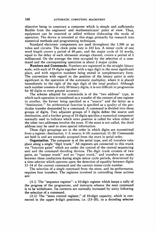
Numbers and Commands. Numbers are registered in the straight binary
scale, with each of 19 digits together with a sign digit in the most significant
place, and with negative numbers being stored in complementary form.
The convention with regard to the position of the binary point is only
significant in the operation of the automatic multiplier, where it is placed
immediately to the right of the sign digit of the total product. Although
each number consists of only 20 binary digits, it is not difficult to programme
for 40 digits or even greater accuracy.
The scheme adopted for commands is of the "two address" type, in
which each operation is considered as a transfer of the content of one register
to another, the former being specified as a "source" and the latter as a
"destination." An arithmetical function is specified as a quality of the par-
ticular transfer demanded by a command. A command is divided into three
groups of digits. Two adjacent groups of 5 digits define the source and
destination, and a further group of 10 digits specifies a numerical component
normally used to indicate which store position is called for when either of
the other two addresses involve the store. If the store is not called, the third
address may be used to store special information.
These digit groupings are in the order in which digits are transmitted
from a register: destination, 1-5; source, 6-10; numerical, 11-20. Commands
are held in and are normally accepted from the store in serial order.
Organization. The computer is of the serial type, and all transfers take
place along a single "digit trunk." All registers are connected to this trunk
via "function gates" which are under the control of the central sequencing
unit and the command decoding devices. The digit trunk consists of two
parts, an "output trunk" and an "input trunk," and transfers are made
between these conductors during single minor cycle periods, determined by
a time selector which operates upon the detection of equality between digits
11-14 of the current command and the current minor-cycle number.
The selection of a single command from the store, and its performance,
requires four transfers. The registers involved in controlling these actions
are:
(A i) The "sequence register": a 10-digit register which keeps a tally of
the progress of the programme, and instructs whence the next command
is to be withdrawn. Its contents are normally increased by unity following
the selection of a command.
(A ii) The "store control register," of 10-digit capacity, which is con-
nected in the upper 6-digit positions, i.e. (15-20), to a decoding selector
AUTOMATIC COMPUTING MACHINERY 169
used to specify which store channel is needed, and in its lower 4 digit
positions (11-14) to the time selector.
(A iii) The "interpreter register," of 20-digit capacity, which is con-
nected to the "source and destination selectors" each possessing 32 outputs.
Some of these registers possess special function gates and may be called
to transfer or receive by a command, as follows:
(B i) The sequence register can be called to "count in," i.e., to increase
its content by a number equal to the number of unit digits entering; to
"add in" on the digit positions 11-20; and to "substitute in" on the same
positions, i.e., reset and add in. Also it can be called to transmit in the digit
group 11-20.(B ii) The interpreter register can be called to transfer out its numerical
content on digit positions 11-20.
The four transfers involved in satisfying a single command are of invari-
able form. They constitute what is called the computer routine and are as
follows :(C i) The content of the sequence register is transferred to the store
control register whose content it replaces.
(C ii) Under the control of the content of the store control register,
the store is allowed to transmit. The time selector finally allows the desired
command to enter the interpreter register via the "input trunk."
(C iii) The command may call for the store to transmit or receive,
hence the numerical part of the command is transferred from the interpreter
to the store control register, replacing any previous content.
(C iv) Under the control of the time selector and the action of the
source and destination selectors, a selected pair of function gates is actuated,
and the desired transfer is performed.
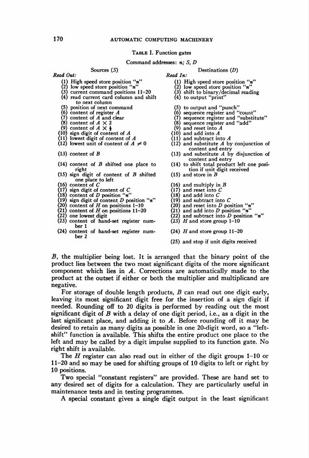
The function gates and their actions are listed in Table I.
The Arithmetical Unit. The arithmetical unit consists of a group of 5ultrasonic delay-line registers of which A, B, C are of 20-digit capacity,
whilst H is of 10 digits only. The fifth register D can store sixteen 20-digit
numbers. Registers A, C, and D can add, subtract, and replace, whilst H
can read in and replace in either of the digit groups 1-10 or 11-20. Register
B is a non-adding register.
Register A is the main accumulator and possesses a number of special
gates for performing the functions of shifting right and left by one place,
as well as reading out the most significant digit and the lowest digit. It is
also capable of certain logical functions. Registers C and D are capable of
reading out the sign digit of their content. This applies to any single number
in D. Registers A, C, and D can read out their contents, and also may do
so with simultaneous reset.
Special functions associated with multiplication have been introduced
which also may be used for other purposes. For automatic multiplication,
registers A, B, and C are coupled together. Register C holds the multipli-
cand whilst B receives the multiplier. The registers A and B are connected
into series circulation together with an extra digit period, for a period of
41 minor cycles during which the multiplier digits are investigated succes-
sively and removed from circulation. The total product is built up by
successive addition and shifting, until actually it occupies registers A and
170 AUTOMATIC COMPUTING MACHINERY
Table I. Function gates
Command addresses: n; S, D
Read Out:Sources (5)
(1) High speed store position "n"(2) low speed store position "n"(3) current command positions 11-20(4) read current card column and shift
to next columnÍ5) position of next command6) content of register A
Í7) content of A and clear8) content of A X 2
(9) content of A X è(10) sign digit of content of A(11) lowest digit of content of A(12) lowest unit of content of A ^ 0
(13) content of B
(14)
(15)
(16)(17)(18)19)
(20)(21)22)
(23)
(24)
content of B shifted one place toright
sign digit of content of B shiftedone place to left
content of Csign digit of content of Ccontent of D position "»"sign digit of content D position "n"content of H on positions 1-10content of H on positions 11-20one lowest digitcontent of hand-set register num-
ber 1content of hand-set register num-
ber 2
Read In:Destinations (D)
(1) High speed store position "n"(2) low speed store position "n"(3) shift to binary/decimal reading(4) to output "print"
(5) to output and "punch"(6) sequence register and "count"(7) sequence register and "substitute"(8) sequence register and "add"(9) and reset into A
(10) and add into A(11) and subtract into A(12) and substitute A by conjunction of
content and entry(13) and substitute A by disjunction of
content and entry(14) to shift total product left one posi-
tion if unit digit received(15) and store in B
(16) and multiply in B(17) and reset into C(18) and add into C(19) and subtract into C _(20) and reset into D position "n"(21) and add into D position "»"(22) and subtract into D position "n"(23) H and store group 1-10
(24) H and store group 11-20
(25) and stop if unit digits received
B, the multiplier being lost. It is arranged that the binary point of the
product lies between the two most significant digits of the more significant
component which lies in A. Corrections are automatically made to the
product at the outset if either or both the multiplier and multiplicand arenegative.
For storage of double length products, B can read out one digit early,
leaving its most significant digit free for the insertion of a sign digit if
needed. Rounding off to 20 digits is performed by reading out the most
significant digit of B with a delay of one digit period, i.e., as a digit in the
last significant place, and adding it to A. Before rounding off it may be
desired to retain as many digits as possible in one 20-digit word, so a "left-
shift" function is available. This shifts the entire product one place to the
left and may be called by a digit impulse supplied to its function gate. No
right shift is available.The H register can also read out in either of the digit groups 1-10 or
11-20 and so may be used for shifting groups of 10 digits to left or right by
10 positions.
Two special "constant registers" are provided. These are hand set to
any desired set of digits for a calculation. They are particularly useful in
maintenance tests and in testing programmes.
A special constant gives a single digit output in the least significant
AUTOMATIC COMPUTING MACHINERY 171
place (i.e., position 1), and a further destination is provided to stop the
sequence. This function is performed if a non-zero digit passes this gate.
A list of the sources and destinations is given in Table I.
Use of the Functions. Whenever a command does not involve the store
or register D, the digits in positions 11-20 may be used for other purposes,
and special 20-digit constants may be compiled by transfer via the H
register. Frequent use is found for special digit groupings in the positions
11-20.Absolute transfer of control can be made by using the read-out faculty
of the interpreter register and the read-in property of the sequence register,
whilst relative transfers can be made by adding into the latter register.
Conditional transfers are made by using the sign-selecting property of the
arithmetical registers. A sign digit is counted into the sequence register,
and an absolute or relative transfer may follow or not according to the sign.
Multiconditional transfers can be made in a single count.
For instance, in terms of the code numbers of Table I, the commands
n; 3, 1,n; 3, 8,
respectively, replace the content of the sequence register by "«" and add
to it; whilst
0; 10, 6
adds a unit to the sequence register if the content of register A is negative.
The use of standard sub-routines as aids to building complete pro-
grammes is adopted. Most sub-routines can, with the aid of the properties
of the sequence register and the multiplicity of adding registers in the
arithmetical unit, be made independent of their actual position in the store.
This simplifies programming. Transfers to and from sub-routines to the
master programme are performed simply by use of the last word position
of the D register, numbered 15. The content of the sequence register is
stored there immediately before the transfer to a sub-routine headed, say,
at position m. One of the commands of the sub-routine adds 1 to this address,
and the last command transfers the content of Du to the sequence register,
which in turn calls for a transfer of control to the next command in the
master programme. This method has the advantage of not involving the
main arithmetical registers A, B, and C during transfers. The commands
needed are shown in Table II.
Input and Output. At present data are inserted via punched cards of the
IBM type. These are read in a columnar fashion, ten binary digits being
Table II
Command Position Command Significance
n-2 15; 5, 20 Stores n- 1 in Dun - 1 m; 3, 7 Transfers to "m"
m — Head of sub-routine
m + r - 1 15; 22, 21 Adds unit to Aem + r 15; 18, 7 Last command of sub-routine;
transfers to "n"n — Continues programme
172 AUTOMATIC COMPUTING MACHINERY
entered from each column. A primary routine of twenty commands is
entered, prior to the feeding of cards, through a group of permanently wired
stepping switches. This routine supplies sufficient information to the com-
puter to enable it to assemble 10-digit data into 20-digit words.
The card reader is also capable of reading decimal data, punched in the
usual decimal manner, and changes from binary to decimal reading and
back are by the computer.
Most programme data are supplied in binary form being mostly of sub-
routine type, and little extra effort is required to punch the cards of the
master programme in binary form.
The X and Y punch positions are used for reading control ; in particular
a Y punch is used to adjust commands as they enter the computer in order
to allow for data which vary with the problem and so on.
Output is obtained in two ways: by standard teletype page printing
and by decimal card punching, again in columnar fashion. Punching is so
arranged that results may be re-inserted later into the computer as problem
data if required.
T. PearceyDivision of Radiophysics
Commonwealth Scientific and Industrial
Research Organization
Australia
Discussions
Minimum Access Programming
The following discussion outlines programming techniques which may
be applied to reduce computation time on certain large scale general purpose
computers. The computers to which these techniques can be applied most
readily have memory systems of large capacity, storing commands and
operands in an alterable medium. These techniques have been applied to great
advantage in the ERA 1101, a computer using a magnetic drum storage
system. On the 1101 the techniques have given an advantage of 20 to 1 in
computing speed over ordinary induction loop techniques for the average
program, with an advantage of 100 to 1 over short stretches.
The internal memory of a typical computer under discussion is divided
into compartments called memory boxes, each memory box having an
address. The computer performs operations such as addition and subtraction
on operands contained in memory boxes. The content of a memory box is
called a "word." The word may either be an operand or a command.1 If
the word is a command, it will consist of a command code and one to four
execution addresses.
The addresses of the memory boxes have a cyclic order. Access to a
memory box is made possible when a coincidence is detected between a
locating register and a storage address register. The storage address register
contains the address of the memory box to which access is desired. As each
memory box is scanned its address is held in the locating register. The
addresses of all the memory boxes pass through the locating register in
their cyclic order every memory cycle.
Let an address be sent to the storage address register. The interval
between the time that the coincidence detector is turned on and the time
AUTOMATIC COMPUTING MACHINERY 173
that a coincidence is detected depends on the distance between the memory
box containing the instruction and the memory box containing the operand.
For each command of a computer there is a minimum interval between
the location of the command and its operand or operands, such that if-a
different interval is programmed the effect would be a loss of operating
time. Attention to these minimum (coding) intervals in construction of a
program is called minimum access programming.
In order to examine minimum access techniques more closely, those
used on a specific machine, the ERA 1101, will be discussed.
The ERA 1101 is a high-speed electronic, general purpose digital com-
puter, having a large internal memory. The computer operates on 24 binary
digits (bits) and uses the one address system of logic. The internal memory
consists of a magnetic drum2 of 16,384 memory boxes. A portion of the
drum in which a digit is stored is called a memory cell and a portion of
the drum in which a word is stored is called a memory box. For each memory
box there are 24 memory cells. All of the digits of a word are read from or
written in a memory box in parallel. Arithmetic operations treat numbers
up to ±247 — 1 in a double length accumulator.
The drum is subdivided into eight groups along its length, so that for
each angular position of the drum, any one of eight memory boxes is avail-
able for access. Each group, by itself, contains 2,048 memory boxes.
Let a memory box on the drum be designated by the address 013^12 • ■ •
a-ißiao held by locating registers, where the a's are binary digits. Then the
digits analog in the locating registers denote the group containing the
memory box, the digits a^ßn denote the quadrant containing the memory
box, and the remaining digits denote the angular position of the memory
box within the quadrant.
00000&>
007T7
\A \A \A\ hiooa\ 1 piooA V 13300a
> \Lmr\ 01000 ILIÜ 02000 \L%\
/oooo
/O 777
OIOOOto
Ol 777
02000&
02777
03000¿o
03 777
-( 12/000-\\22000¡ i \23000\0 I I e» j 1IOOO I I £0 I I20O0 b
/ Wrrrl & / \1z777f ¿, I 123777/
J\Jj±J\h=J\l/300o
Z3777
07000
¿o
07777
17OO OOUU I
777 IZ7777
Fig. 1. Address mapping on drum for 1 interlace.
174 AUTOMATIC COMPUTING MACHINERY
2° 212 2'*29 28 27 26 2» 2-SAR
LR
22 2I 20
o13 o122 2 2 2 28 27 26 25 24 23 2* 21 2°
Fig. 2. Patching connections for IB interlace.
In order to select memory locations around the drum so that they are
associated with consecutive memory boxes, the storage address register
(SAR) is connected to the locating register (LR) through an interchange-
able plugboard called an interlace chassis.
If the digits of the SAR are carried into their corresponding positions
in the LR, then consecutive addresses are located in consecutive memory
boxes. This is called a one interlace.
For adjacent memory boxes, with any interlace, the difference between
their addresses is called the increment. The one interlace has an increment
of one.
One may see that there are 14! ways to interlace the drum with the
storage address register, although only a few of these have been useful.
Those used most frequently are the 1, 2, 4, 8, 16, 32, 64, 128 and IB inter-lace. The special interlace hook-up called the IB interlace has been found
useful for loading the drum. The interlace may be dialed.
With a 64 interlace, memory boxes having consecutive addresses are 64
cell periods apart. One cell period is the interval between two adjacent
memory boxes on the drum and is equal to 8 microseconds. Also for a 64
interlace we have an increment of 32.
Starting with address zero, adjacent memory boxes have the following
addresses for 64 interlace. Octal notation is used.
X is the group index :
0X0000X0400X1000X140
0X7401X0001X0401X100
1X7001X7402X0002X0402X100
etc.
AUTOMATIC COMPUTING MACHINERY 175
Each command consists of a six bit command code, a2%, • • •, an, four
skip bits an, • • •, au and a fourteen bit execution address an, • • • ,a0.
A 1 appearing in any one of the skip bit positions of a command can be
used to advance the program address counter by pulsing one of its first ten
stages. Four selector switches determine which stages are to be pulsed by
the skip bits should they appear.Delays inserted in the skip bit lines allow multiple skip bits to be used
with the same command.
One skip bit setting used by the author carries
»is into 2°, aie into 21, and an into 22
with the selector switch for an turned off.
Then if a command appears in box y with l's in au, au and an, the next
command will appear in address y + 2° + 21 + 22 + 1.
If an interlace of one were used, with no skips, at least one drum revo-
lution would be required for each instruction. By choosing the proper inter-
lace and skips, however, operands and instructions may be so placed that
several instructions are executed in one drum revolution.
In order to coordinate the philosophy of minimum access programming
with techniques used in the ERA 1101, a discussion of the 1101 commands
is in order.
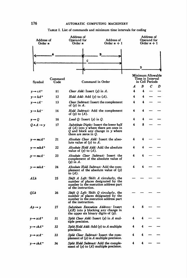
The list given in Table I gives the commands and their corresponding
minimum allowable access times. In the table interpret "y" as the address
of the memory box containing the word "(y)." The symbol "—*" is inter-
preted as "goes to." AL is the left half or higher order accumulator and
AR is the right half or lower order accumulator. A is a 48-bit electronic
register and Q is a 24-bit electronic register. Negative numbers are expressed
by complements.
The intervals A, B, C and D specified in Table I are minimum values.
Should a shorter interval be programmed, the only effect is a loss of oper-
ating time. The interval is then automatically lengthened by the duration
of a complete drum revolution.
The intervals of commands 17, 27, 35 and 36 are valid for a single
writing operation. The minimum allowable interval between two successive
writing operations in the same group is 256 cell periods. In different groups,
the minimum interval is 4 cell periods. Note that a reading operation will
normally occur between successive writing operations.
The minimum interval for either C or D of commands 25 and 26 is
approximately 6 + 0.33k cell periods where k is the number of places
shifted.
Fig. 3. Patching connections for a 64 interlace.
176 AUTOMATIC COMPUTING MACHINERY
Table I. List of commands and minimum time intervals for coding
Address ofOrder n
Address ofOperand for
Order »Address of
Order n + 1
Symbol
y—+cA +
y — hA+
y-*-cA~
y^-hA-
y-*Q
Q*A -*-y
y-+mcA+
y-*mhA+
y-+mcA~
y-*mhA~
ALk
QLk
Ap-*y
y-*-scA+
y — shA+
y -*■ scA~
y -» shA ■
CommandCode
11
12
13
14
16
17
21
22
23
24
25
26
27
31
32
33
34
Command in Order
Clear Add: Insert (y) in A.
Hold Add: Add (y) to (A).
Clear Subtract: Insert the complementof (y) in A.
Hold Subtract: Add the complementof (y) to 04).
Load Q: Insert (y) in Q.
Substitute Digits: Insert the lower halfof (A) into y where there are ones inQ and block any change in y wherethere are zeros in Q.
Absolute Clear Add: Insert the abso-lute value of (y) to A.
Absolute Hold Add: Add the absolutevalue of (y) to (A).
Absolute Clear Subtract: Insert thecomplement of the absolute value of(y) in A.
Absolute Hold Subtract: Add the com-plement of the absolute value of (y)to (A).
Shift A Left: Shift A circularly, thenumber of places designated by thenumber in the execution address partof the instruction.
Shift Q Left: Shift Q circularly, thenumber of places designated by thenumber in the execution address partof the instruction.
Substitute Execution Address: Insert(AR) into y blocking any change inthe upper six binary digits of (y).
Split Clear Add: Insert (y) in A mul-tiple precision.
Split Hold Add: Add (y) to A multipleprecision.
Split Clear Subtract: Insert the com-plement of (y) in A multiple precision.
Split Hold Subtract: Add the comple-ment of (y) to (A) multiple precision.
Address ofOperand forOrder n + 1
Minimum AllowableTime in Intervalin Cell Periods
A B C D
4 4 — —
4 4 — —
4 4 — —
4 — —
4 _ _
8 — —
4 4 —
4 4 —
4 4 —
4 8 — —
4 4 — —
4 4 — —
4 4 — —
4 4 — —
AUTOMATIC COMPUTING MACHINERY
Table I—Continued
CommandSymbol Code Command in Order
A-*-y 35 Store A: Insert (AR) into y.
Q-*y 36 Store Q: Insert (Q) into y.
zero -* AR 37 Cïear 4.R: Clear the lower order accu-mulator.
Q->-cA 41 Clear Add from Q: Insert (Q) in .4.
Q — hA 42 HoW ¿<W /row Q: Add (Q) to (¿).
4 -»■ cQ 43 Transmit A to Q: Insert (4.R) in Q.
QJ 44 Q Jump: If (Q) is negative, insert (y)in the 5^41?. In either case shift Qcircularly one place to the left.
J 45 Jump: Insert y in the SAR.
cJ 46 Sign-Conditional Jump: If (A) is nega-tive, insert y in the SAR.
zero / 47 Zero-Conditional Jump: If (.4) is zeroinsert y in the 5^4i?. In either casesubtract one from A.
Qy-*-cA 51 Clear Logical Multiply: Insert (y) inAR where there are ones in Q, block-ing a change in AR where there arezeros in Q.
Qy — hA 52 Hold Logical Multiply: Add (y) toiAR) where there are ones in Q, block-ing a change in AR where there arezeros in Q.
y-*-P 53 Print Only: Print the six bit characterwhose address is y.
y -► P/P 54 Print and Punch: Print and punch thesix bit character whose address is y.
IS 55 Intermediate Stop: Stop the computerand turn on the intermediate stoplight. Proceed only after the operatorpushes the start button.
05 56 Optional Stop: Stop the computer ifthe optional stop button has beenpushed, and give suitable indication.
FS 57 Final Stop: Stop the computation andturn on the final stop light.
Qy-cA 61 Clear Multiply: Obtain (y)-(Q) in A.
Q-y — hA 62 Hold Multiply: Add (y) ■ (Q) to (A ).
A/y-*'cQ 63 Divide: Obtain (A)/(y). Find the quo-tient in Q and the non-negative re-mainder in A.
65 Optional Jump: Same as optional stopexcept when the computer is on TEST.If on TEST, and the optional jumpswitch is on, then this command isthe same as the jump command.
66 Do Nothing: Performs no operation.
y + 1 -» A 71 Clear Add Plus One: Insert (y) + l inA.
178 AUTOMATIC COMPUTING MACHINERY
The intervals of commands 53 and 54 are for a single print operation.
The minimum allowable interval between two successive print operations
is approximately 19,000 cell periods or 150,000 microseconds. Should a
shorter interval be programmed it will automatically be lengthened to this
interval. Note, however, that while a print command is being executed, the
computer can proceed with the program of instructions provided the follow-
ing orders do not call for another print operation.
Although interval B of command 62 is indicated as being a minimum of
13 cell periods, a 12 cell period may be used for B when interval A is pro-
grammed at no more than 4 cell periods. Under this condition, interval C
is therefore 16 cell periods.
The 66 command performs no operation but its skip bits may be used
to augment those of the previous command.
In writing a minimum access program, the programmer sometimes takes
advantage of induction loop programming methods. A case in point is the
matrix multiplication of two 10 X 10 matrices. The solution of the problem
gives X • Y = Z, where X, Y and Z are 10X10 matrices.A portion of the program of a matrix multiplication is shown in Table II.
Skips are not used as the program was written before they were made
available. In preparation for the execution of this program, elements of X
are inserted row by row in memory boxes whose addresses are designated
by the following table of addresses at 128 interlace in group <j>. Octal nota-
The elements of Y transpose are inserted row by row in memory boxes
whose addresses are designated by the table of addresses at 128 interlace,
but in group 1.Z is written in a similar block, where the elements of the first row are
in consecutive addresses at 64 interlace.
The program of Table II obtains the products of the rows of X and a
column of Y in 30 revolutions of the drum, and the entire matrix product
has been clocked at 8.9 seconds where no overflow occurred during the
multiplication. If a z„- occurs larger than 223 — 1, then 223 — 1 is subtracted
from Zij and a conditional jump is executed.
The scaling routine which starts at address 30540 does not utilize mini-
mum access techniques. This is an ordinary induction loop routine. A
minimum access attack may be made on the scaling routine at the expense
of memory space.
It is possible to manufacture portions of the minimum access program
in the computer. This manufactured program may be punched out ready
for use.From the program of Table II and from other material presented above,
it may be concluded that : Arranging operands and instructions so that they
AUTOMATIC COMPUTING MACHINERY 179
Table II. Matrix multiplication on 64 interlace of two 10 X 10 matrices
Insert the following commands at 1 B interlace (Octal notation is used) :
Memory Box
03120031210312203123
03131
0322003221
11111111
2727
Command
03030303
0303
10101111
0000
31713171
11 03 14 71
3272
Explanation
3120 at 1 B interlace be-comes 10031 at 64 interlace.
The operation starts withthe command in memorybox 10031.
3220 at 1 B interlace be-comes 10032 at 64 interlace.
03231
0332003321
27 03 04 72
4545
0101
0001
7131
3220 at 1 B interlace be-comes 10033 at 64 interlace.
0333003331
At 64 interlace:
30500
30501305023050330504305053050630507
30534305353053630537
31001310023100331004
4545
0103
0405
7100
11 03 05 36
35112711122745
00007700
11351135
03030303030300
00037700
01010101
05050505050500
00077700
10301040
37350707340700
40416500
02030405
Minus ten counter.
310233102431025
31031
31037
113545
010103
107000
242500
00 01 20 00
00 00 00 02
Subroutines starting in memory boxes 31041, 31101, 31141, 31201, 31241, 31301, 31341,and 31401 have been omitted to conserve space. Their function is similar to the sub-routines of 31001 to 31025 and 31441 to 31465.
31441314423144331444
11351135
01010101
14301440
42034405
3146431465
3545
0103
7000
2500
31471 00 01 24 40
180 AUTOMATIC COMPUTING MACHINERY
Memory Box
3000030001300023000330004
1116621662
Table II—Continued
Command
0101010101
0000300040
0102030405
Explanation
zero A*u — Q
Q-yu-+hAxu-+Q
QjV~kA
300233002430025300263002730030300313003230033
166246144645123545
010103010303010003
007020200005200000
242526273140320040
*i,io-*(?Q-yiy — hA
37777777 -+hA-
37777777 — hA+
The subroutines starting in memory boxes 30040, 30100, 30140, 30200, 30240, 30300,30340, and 30400 are similar to the subroutines of 30000 to 30033 and 30440 to 30472.
occur as close as possible to the minimum allowable coding intervals shortens
the computation time considerably. In the program of Table II the method
used to obtain a product of a row by a column is faster than an ordinary
induction loop program by a factor of approximately 50. A 10 X 10 matrix
multiplication may be performed in approximately 8 seconds using minimum
access techniques.
1 In the UNIVAC a word contains two commands.2 A. A. Cohen, "Magnetic drum storage for digital information processing systems,"
MTAC, v. 4, p. 31-39.
Engineering Research Associates
Arlington, Virginia
David P. Perry
Bibliography Z-XX
1. William A. Allen & Richard H. Stark, "Ray tracing using the IBMCard Programmed Electronic Calculator," Optical Society of America,
Jn., v. 41, p. 636-640.The IBM Card Programmed Electronic Calculator is described, and the
manner in which the ray tracing equations are modified in order to adapt
them especially for this calculator is outlined. Equations are given and
procedure explained for tracing meridional and skew rays through a spheri-
cal lens system. Numerical examples are given for both a meridional and a
skew ray trace, and the accuracy of the machine calculations is discussed.
Ethel MardenNBSCL
2. Franz L. Alt, "Evaluation of automatic computing machines," Prod.
Eng., v. 22, Nov. 1951, p. 146-152.The author explains the why and wherefore of large scale automatic
computing equipment and predicts the further growth of such equipment
as engineering tools. The essential features of digital machines are described
and contrasted with those of analogue machines and some advantages and
automatic computing machinery 183
disadvantages of the two types are enumerated. A summary table of vital
statistics is included on three computers in operation at present (EN I AC,
SSEC, and SEAC), and three computers under test as of the early part of
1951 (Mark III, UN I VAC, and ERA). Despite the advances alreadyachieved with the aid of such machines in the fields of engineering, mathe-
matics, physics, industrial management and control, military science, etc.,
according to the author we have only begun to scratch the surface of the
vast regions now capable of being investigated.
J. H. LevinNBSCL
3. Anon., "Office robots," Fortune, v. 45, Jan. 1952, p. 82-87.This article gives an overall account of the history of "electronic brains"
from the development of EN I AC in 1946 to the present time. A few of the
better known machines are discussed from those of the ninety organizations
throughout the country working on some form of computer. A few diagrams
are shown to illustrate the very rudiments of how a high-speed computer
computes. Examples are given of the savings attained for some companies
employing these machines. Several examples of special purpose machines
are discussed, such as one developed by the Bell Telephone Laboratories,
called the Automatic Message Accounting Machine, which automatically
records and accounts toll and local calls and makes out customers' bills.
Donald O. LarsonNBSCL
4. A. A. Auerbach, J. P. Eckert, Jr., R. F. Shaw, J. R. Weiner, & L. D.Wilson, "The BINAC," IRE, Proc, v. 40, Jan. 1952, p. 12-29.The logical design, instruction code, and some typical circuitry of the
Binary Automatic Computer, BINAC, are all described here, though neces-
sarily quite concisely. Such broad coverage in one article should appeal to
a newcomer to the field, although it requires very thoughtful reading. The
expert will certainly be interested because BINAC was the first of its genus
of high-speed, serial, digital computers to be completed in this country, its
pulse repetition rate, 4 mc/s, is still the highest in use, and BINAC can be
a relatively perspicuous introduction to the much more complex UNIVAC's.
The serious student of BINAC's and UNIVAC's circuitry should notice
three basic changes made in the UNIVAC's:
1) The pulse repetition frequency was reduced from 4 to 2.25 mc/s.
2) In the pulse reforming circuit a flipflop was substituted for the
Guillemin line.3) In the mercury delay line memory simple impulse excitation was
replaced by gating a carrier wave.
R. D. ElbournNBSEC
5. F. P. Cozzone, "Organizing a computer center in the engineering depart-
ment," Prod. Eng., v. 23, Jan. 1952, p. 136-141.The author stresses the importance of computing facilities in engineering
analysis. A brief outline is given of some types of digital and analogue
184 AUTOMATIC COMPUTING MACHINERY
computers as well as some varieties of auxiliary data recording and process-
ing equipment. A table is included classifying five computers according to
their adaptability to different types of aircraft design problems. Finally
some suggestions are given on the organization of a sample engineering
computing facility. This article is carelessly written and contains a number
of errors of fact. For example, the IBM Defense Calculator is identified
with the SSEC in Fig. 2 and with the Card Programmed Calculator inTable III.
J. H. LevinNBSCL
6. J. W. Donnell, "If computation costs too much," Chemical Engineering,
v. 58, Dec. 1951, p. 138-141.This article points to high-speed mechanical and electronic aids to calcu-
lation for savings in money and man power for computational problems
arising in engineering. Ways in which engineering offices can make the most
effective use of high-speed computing machinery are given. Several ex-
amples are described illustrating this point.
Donald O. LarsonNBSCL
7. Donald P. Feder, "Optical calculations with automatic computing
machinery," Optical Society of America, Jn., v. 41, Sept. 1951, p.
630-635.This paper describes the procedures employed for tracing rays through
an optical lens system, using automatic computing machinery, namely, the
IBM Card Programmed Electronic Calculator and the SEAC. There are
two main phases of the computation: finding the point of incidence of a
ray with the following surface, and computing the direction cosines of the
refracted ray. It is shown how the process may be modified to apply to
aspheric surfaces. A process is outlined for use on the CPEC for the com-
putations of first and third order imagery and for the extension of this
calculation to aspheric surfaces.
Ethel MardenNBSCL
8. H. H. Goode, "Simulation—its place in system design," IRE, Proc,
v. 39, Dec. 1951, p. 1501-1506.The uses of both analogue and digital computers as aids in the task of
designing large complex systems are discussed in broad general terms.
Careful study of each problem rather than adherence to any universal rule
is urged.R. D. Elbourn
NBSEC
9. H. J. Gray, Jr., "Logical description of some digital-computer adders
and counters," IRE, Proc, v. 40, Jan. 1952, p. 29-33.A set of logical block diagram symbols and ordinary (non-Boolean)
algebra are used to describe a few binary adder-subtractors and counters.
R. D. ElbournNBSEC
AUTOMATIC COMPUTING MACHINERY 185
10. B. Kazan & M. Knoll, "Fundamental processes in charge-controlled
storage tubes," RCA, Review, v. 12, Dec. 1951, p. 702-753.This paper is a review of a large, important, and delicate subject. The
subject is large because it includes secondary emission, photo emission,
photo conduction, and electron-induced conduction. The importance of
these processes lies in the civilian and military uses of the tubes for which
they are the heart. Some idea of the possible extent of these applications
can be gained by realizing that the term covers not only all the many types
of storage tubes for computer use, but also includes all television "pick-up"
tubes (such as the Image-Orthicon), direct viewing tubes (such as the
"Snooperscope") and all types of signal converter tubes. The subject is
delicate in two ways: first, the processes themselves are very delicate,
varying drastically upon very slight provocation; secondly, so few of the
many attempts to produce useful storage tubes have been successful that
many of the potential users of such tubes have become discouraged.
For inventors, the field of charge-controlled storage'tubes is wide open,
and the authors have written the primer on the subject. Part I tells how
the basic processes behave under the action of light and electron bombard-
ment; Part 2 gives definitions of terms used in the business; Part 3 tells
about storage tube reading and writing; and Part 4 gives 97 bibliography
references. A great many of these references, particularly those dealing
with the basic processes, are written in German, but the authors have done
us an extra service by giving a summary of each paper in English. The list
is reasonably complete, although no attempt was made to catalogue the
recent spate of papers which have been unraveling the theory of the Williams
method of cathode ray tube storage. The authors of this paper have done a
real service in bringing together so much of the information on storage tubes.
Arthur W. HoltNBSEC
11. A. J. Lephakis, "An electrostatic-tube storage system," IRE, Proc,
v. 39, November 1951, p. 1413-1415.A binary storage system is described which should prove useful in
studying certain communication problems. The system comprises two chan-
nels, each using an MIT electrostatic storage tube, with provision for
writing incoming pulses in one channel while recovering previously stored
pulses from the other. The order of incoming pulses is preserved during
storage, but the time rate of recovery may be faster or slower than the
original writing rate. A block diagram and two typical circuits are shown.
Performance details are discussed.
William W. DavisNBSEC
12. Office of Naval Research, Digital Computer Newsletter, v. 4, April1952, 6 pages.The contents are as follows :
1. Whirlwind I.2. The ONR Relay Computer.3. The ABC.4. The SEAC.
186 automatic computing machinery
5. TheSWAC.6. The Circle Computer.7. Moore School Automatic Computer (MSAC).
8. The UNIVAC.9. The Jacobs Instrument Company Computers (JAINCOMP).
10. The CADAC.11. Consolidated Electronic Digital Computer Model 30-201.12. The ACE Pilot Model.13. Data-Handling Devices.
13. H. Rutishauser, A. Speiser, & E. Stiefel, "Programmgesteuertedigitale Rechengerate," Inst. f. angew. Math., Mitt. No. 2, 1951, 102pages.
This is a comprehensive exposition of the logical organization of auto-
matic digital computers and of the principles of their physical realization.
It is the first publication of its kind in German and far better than most
similar writings in English. Concisely and precisely written, complete, and
as unbiased as is possible in this controversial field, it is highly recommend -
able as an introduction to the subject.
The first chapter deals briefly with the why and how of automatic
computation, its history, relations to formal logic and neurophysiology,
and (perhaps too briefly) applications. A second chapter lists and describes,
in only four pages, the major components of automatic computers. The
third chapter explains in full detail the various methods for representing
numbers (binary, coded decimal; fixed vs. floating point) and for carrying
out the elementary arithmetic operations. There follows a chapter on coding
and programming, including such topics as flow diagrams, branch points,
single and multiple address codes, modification of instructions by arith-
metic operations, and a completely carried out example (multiplication of
two matrices). Methods of evaluating mathematical functions as well as
checks, both built-in and programmed, are also discussed. The final chapter
describes the basic circuits occurring in computers, such as "and" gates,
"or" gates, adders, etc.; the several methods of number storage (acoustic,
magnetic, electrostatic) ; and media for input and output. There is a sum-
mary table of computer developments as of December 1949 and a compre-
hensive bibliography.Franz L. Alt
NBSCLNews
Association for Computing Machinery.—The spring meeting of the Association was
held on May 2 and 3, 1952, at the Mellon Institute, Pittsburgh, Pennsylvania. On May 2nd
at 7:00 p.m. a banquet was held at which time a talk, "History of mechanical computing
machinery," was presented by George C. Chase, Monroe Calculating Machine Company,
Orange, N. J. The program for the meeting was as follows:
May 2, 1952, 10:00 a.m.
General Session Franz L. Alt, NBSCL and President of
ACM, ChairmanAddress of Welcome E. R. Weidlein, President, Mellon Insti-
tute
Evaluation of Automatic Computing Irven Travis, Burroughs Adding Machine
Co.
AUTOMATIC COMPUTING MACHINERY 187
Transistor Physics
Mark IV
May 2, 1952, 2
Computers and Components I
Special-Purpose Digital Data-Processing
Computers
The Remington-Rand Punch-Card Elec-
tronic Computer, Type 409-2
The Elecom 100 General Purpose Computer
The Quadratic Arc Computer (QVAC)
A System for Counting and Recording Elec-
trical Impulses in Printed Decimal Form
The Logical Organization of the New IBM
Scientific Calculator
W. Shockley, Bell Telephone Laboratories
H. H. Aiken, Harvard Computation Lab-
oratory
30 to 5:00 p.m.
Jan. A. Rajchman, RCA. Chairman
B. M. Gordon and R. N. Nicola, Labora-
tory for Electronics, Inc.
L. P. Crosman, Remington-Rand Corp.
Albert Auerbach, Electronic Computer
Corporation
M. J. Mendelson, Northrup Aircraft, Inc.
J. L. Lindesmith, Clary Multiplier Corp.
N. Rochester, IBM Corp.
May 2, 1952, 2
Mathematical Applications I
Engineering Problems Requiring Automatic
Computing Facilities
Digital Computer Methods for Problems
which Involve Linear Inequalities
Computational Problems of Linear Pro-
gramming
Small Problems on a Large Computer
Firing Table Computations on the ENIAC
Small-Scale Research and Automatic Com-
puting
May 2, 1952,2:
Theory I—Information and Control
Use of Computing Machinery in Applica-
tions of Information Theory
An Upper Bound on the Informational Ca-
pacity of a Synapse
Automatic Control of Machinery
The Maze Solving Computer
A Chart Method for Simplifying Truth
Functions
30 to 5:00 p.m.
Mina Rees, ONR, Chairman
E. L. Harder, Westinghouse Electric Corp.
Alex Orden, Hq. U.S.A.F.
A. Charnes, Carnegie Institute of Tech-
nology
C. W. Adams, MITH. L. Reed, Jr., Aberdeen Proving Ground
E. C. Berkeley, Edmund C. Berkeley &
Associates
30 to 5:00 p.m.
J. H. Curtiss, NBS, ChairmanW. G. Tuller, Melpar, Inc.
W. S. McCullough, Neuropsychiatrie In-
stitute, Donald MacKay, Kings College,
London
P. L. Nies, G. P. Tanquary, D. R. Auf-derhiede, D. W. Brown, C. J. Jacoby,
R. B. Keller, Harvard Univ.
R. A. Wallace, L. and O. Research and
Development Co.
E. W. Veitch, Burroughs Adding Machine
Co.
May 3, 1952, 9:30 to 12:00 Noon
Computers and Components II
Transistor Circuits for Computers
Standardized Printed Circuit Units for Digi-
tal Computers
Non-Linear Switching Elements
John D. Dillon, Air Force Missile Test
Center, Cocoa, Florida, Chairman
J. H. Felker, Bell Telephone Laboratories
D. L. Johnson, Elliott Brothers, Ltd., Bore-
ham wood, England
B. Moffat, F. A. Schwertz, Mellon Insti-
tute, B. O. Marshall, Air Force Cam-
bridge Research Center
188 AUTOMATIC COMPUTING MACHINERY
Optical Elements for Computers
The Selenium Rectifier—A Non-Linear and
Asymmetric Resistance Element
May 3, 1952, 2:1
Theory III—Logic and Circuit Synthesis
Formal Logic and Switching Circuits
Minimization Synthesis of Two-Valued
Feed-Back Circuits
B. O. Marshall, Air Force Cambridge
Research Center, J. R. Bowman, F. A.
Schwertz, Mellon Institute
N. Hardy, International Resistance Co.
2:00 to 5:00 p.m.
H. H. Aiken, Harvard Computation Lab-
oratory, Chairman
Theodore Kalin, Air Force Cambridge
Research Center
William Burkhart, Monroe Calculating
Machine Co.
May 3, 1952, 9:30 to 12:00 Noon
Mathematical Applications II
Discussion on the Use and Construction of
Subroutines
Alston S. Householder, Oak Ridge Na-
tional Laboratory, Chairman
James Alexander, Argonne National Lab-
oratory, Herman H. Goldstine, IAS,
Joseph H. Levin, NBS, H. Rubenstein
and J. D. Rutledge, Remington-Rand,
Inc.
May 3, 1952, 9
Theory IÍ—Mathematical
A Unified Approach to the Monte Carlo
MethodThe Solution of Boundary Value Problems
by the Method of Kernel Functions
Boundary Value Problems in Doubly Con-
nected Domains
May 3, 1952,
Computers and Components III
Digital Storage Using Ferromagnetic Ma-
terials
Some Recent Research on Ultrasonic Propa-
gation in Solid Media
Static Magnetic Memory—Its Application
to Computers and Controlling Systems
Static Magnetic Memory for the ENIAC
Magnetic Binaries in the Logical Design of
Information Handling Machines
:30 to 12:00 Noon
C. V. L. Smith, ONR, Chairman
J. H. Curtiss, NBS
Stefan Bergman, Stanford Univ.
Franz L. Alt, NBS
2:00 to 5:00 p.m.
L. P. Crosman, Remington-Rand Corpora-
tion, Chairman
P. D. Atkinson, A. E DeBarr, R. Miller-
ship, R. C. Robbins, Elliott Brothers,
Ltd.T. F. Rogers, Air Force Cambridge Re-
search Center
An Wang, Wang Laboratories
Isaac L. Auerbach, Burroughs Adding
Machine Co.
N. B. Saunders, Transducer Corp.
May 3, 1952, 2:00 to 5:00 p.m.
Mathematical Applications IV
Discussion on the Use and Construction of
Subroutines
Alston S. Householder, Oak Ridge Na-
tional Laboratory, Chairman
Roselyn Lipkis, NBS, David J. Wheeler,
University of Illinois and University of
Cambridge, John W. Carr, MIT, GraceM. Hopper, Remington-Rand, Inc.
AUTOMATIC COMPUTING MACHINERY 189
Characteristic Numbers and Their Use in
the Decomposition of Switching Functions
Rectifiers as Elements of Switching Circuits
The Theory of Counting Techniques
The Application of Counting Techniques
Warren L. Semon, Harvard Computation
Laboratory
Peter F. Strong, Harvard Computation
Laboratory
Theodore Singer, Harvard Computation
Laboratory
Robert L. Ashenhurst, Harvard Compu-
tation Laboratory
University of California at Los Angeles.—On April 30, May 1-2, 1952, at UCLA, asymposium on electronic computers was held under the sponsorship of the Los Angeles
IRE Professional Group on Electronic Computers and the Department of Engineering of
the University. The program was as follows:
Wednesday, April 30, 1952Registration
Opening Session
Introduction
Welcome
Keynote—Engineering Tomorrow's Com-
puters
Session on Magnetic Devices
Design Features of a Magnetic Drum Mem-
ory for the National Bureau of Standards
Western Automatic Computer (SWAC)
Problems Involved in Magnetic Tape Re-
cording
Survey of Tape Drive Systems
Session on Analog Devices
An Electro-Mechanical Multiplier for Ana-
log Computer Application
The Thermal Analyzer—A Special Purpose
Analog Computer
Panel Discussion—Utilization of Germa-
nium Diodes
Panel Discussion—Designing for Maximum
Reliability
R. G. Canning, Naval Air Missile Test
Center, Point Mugu, Calif.
L. M. K. Boelter, Department of Engi-
neering, UCLA, Chairman
H. D. Huskey, NBSINA
John J. Connolly, The Rand Corporation,
Chairman
R. Thorensen, NBSINA
Norman E. Gibbs, Raytheon Manufactur-
ing Company
Harold Sarkissian, Computer Research
Corporation
W. L. Martin, Department of Engi-
neering, UCLA, Chairman
S. E. Dorsey, Naval Ordnance Test Sta-
tion, Inyokern, Calif.
W. L. Martin and R. Bromberg, Depart-
ment of Engineering, UCLA
L. L. Kilpatrick, North American Avia-
tion, Inc., Chairman
Norton Bell, Consolidated Engineering
Corporation
L. S. Pelfrey, Hughes Aircraft Co.
W. Speer, Computer Research Corp.
A. S. Zukin, Hughes Aircraft Co.
Harry T. Larson, Hughes Air-craft
Company, Chairman
John J. Connoly, The Rand Corp.Harry D. Huskey, NBSINARobert Lusser, Naval Air Missile Test
Center, Point Mugu, Calif.
Robert Rawlins, Lockheed Aircraft Cor-
poration
William Wagenseil, Hughes Aircraft
Company
190 OTHER AIDS TO COMPUTATION
Thursday,
Session on Programming and Coding
An Approach to the Use of the IBM Card-
Programmed Electronic Calculator in the
Solution of Engineering Calculations
Some General Precepts for Programmers
Programming for On-Line Computations
The Human Computer's Dreams of the
Future
Automatic Program Control Utilizing a
Variable Reference for Addressing
Programming for Finding Characteristic
Values of Mathieu's Equation and the
Spheroidal Wave Equation
Session on Input-Output Equipment
The Benson-Lehner Photoformer
Input-Output on the New IBM Scientific
Computer
An Accurate Digital-Analog Function Gen-
erator
Some Techniques of Analog to Digital Con-
version
The Teleplotter, A Digital Plotting Device
Summary Session
Introduction
Speakers
May 1, 1952
Roselyn Lipkis, NBSINA .Chairman
Murray L. Lesser, Northrop Aircraft, Inc.
E. C. Yowell, NBSINAH. Luxenberg, Hughes Aircraft Co.
Ida Rhodes, NBS (Read by R. R. Rey-nolds, NBSINA)
A. S. Zukin, Hughes Aircraft Co.
Gertrude Blanch, NBSINA
H. Doeleman, Electronic Engineering
Company of Calif., Chairman
D. L. Pitman, Benson-Lehner Corp.
M. M. Astrahan, IBM Corporation
W. A. Farrand, North American Aviation,
Inc.
H. E. Burke, Consolidated Engineering
Corporation
Donald F. Belloff, Telecomputing Corp.
R. L. Sisson, Computer Research Corp.
D. H. Lehmer, NBSINALouis N. Ridenour, International Tele-
meter Corp.
Friday, May 2, 1952
Tours were conducted to the following facilities:
The Rand Corporation,
Telecomputing Corporation,
California Institute of Technology,
Northrop Aircraft, Inc.
OTHER AIDS TO COMPUTATION
Linear Algebraic Systems and the REAC1. Introduction. A great variety of problems in both pure and applied
mathematics involves, either directly or indirectly, the solution of systems
of simultaneous linear algebraic equations. Although the solution of such a
system can readily be indicated by determinants, it is found that the attain-
ment of actual numerical answers frequently becomes laborious for systems
of order greater than three. Further, it is found that a great deal of effort
has been, and is being, expended in the development of numerical procedures
and in the design and development of computers which can be applied to
such linear systems.
The approach in this instance is somewhat different. Here we are inter-
ested in extending the utility of an existing computer, or to be more specific,