16 ENGINE ELECTRICAL – Charging System CHARGING SYSTEM GENERAL INFORMATION The charging system is a system which charges the battery with the alternator output to keep the battery charged at a constant level during varying electrical load. Operation Rotation of the excited field coil generates AC voltage in the stator. This alternating current is rectified through diodes to DC vol- tage having a waveform shown in the illustration at left. The average output voltage fluctuates slightly with the alterna- tor load condition. When the ignition switch is turned on, current flows in the field coil and initial excitation of the field coil occurs. When the stator coil begins to generate power after the engine is started, the field coil is excited by the output current of the stator coil. The alternator output voltage rises as the field cur- rent increases and it falls as the field current de- creases. When the battery voltage (alternator S terminal voltage) reaches a regulated voltage of approx. 14.4V, the field current is cut off. When the battery voltage drops below the regulated vol- tage, the voltage regulator regulates the output voltage to a constant level by controlling the field current. In addition, when the field current is constant, the alternator output voltage rises as the engine speed increases. Stator coil Field coil Voltage re- gulator Charge light Ignition switch Battery B L S Main Index 16 Index Time Voltage About 14.5V
Transcript
16 ENGINE ELECTRICAL – Charging System
CHARGING SYSTEMGENERAL INFORMATIONThe charging system is a system which chargesthe battery with the alternator output to keep the
battery charged at a constant level during varyingelectrical load.
OperationRotation of the excited field coil generates AC voltage inthe stator.This alternating current is rectified through diodes to DC vol-tage having a waveform shown in the illustration at left.The average output voltage fluctuates slightly with the alterna-tor load condition.
When the ignition switch is turned on, current flowsin the field coil and initial excitation of the fieldcoil occurs.When the stator coil begins to generate power afterthe engine is started, the field coil is excited bythe output current of the stator coil.The alternator output voltage rises as the field cur-rent increases and it falls as the field current de-creases. When the battery voltage (alternator S
terminal voltage) reaches a regulated voltage ofapprox. 14.4V, the field current is cut off. Whenthe battery voltage drops below the regulated vol-tage, the voltage regulator regulates the outputvoltage to a constant level by controlling the fieldcurrent.In addition, when the field current is constant, thealternator output voltage rises as the engine speedincreases.
Stator coil
Field coilVoltage re-gulator
Charge light Ignitionswitch
Battery
B
L
S
Time
Voltage
About14.5V
16 ENGINE ELECTRICAL – Charging System
ALTERNATOR SPECIFICATIONS
Items
Type Battery voltage sensingRated output V/A 12/110Voltage regulator Electronic built-in type
SERVICE SPECIFICATIONS
Items Standard value LimitRegulated voltage V(Ambient temp. at voltage –20C 14.2–15.4 –
20C 13.9–14.9 –Regulated voltage V(Ambient temp. at voltage 60C 13.4–14.6 –regulator) 80C 13.1–14.5 –
Rotor coil resistance Ω Approx. 2.6 –Output current – 70% of nominal output current
SPECIAL TOOL
Tool Tool number and name Supersession Application
MB991348
Test harness set
EMB991348 Inspection of ignition primaryvoltage (power transistor con-nection)
16 ENGINE ELECTRICAL – Charging System
ON-VEHICLE SERVICEALTERNATOR OUTPUT LINE VOLTAGE DROP TEST
Alternator
Voltmeter
Ammeter
Battery
–
+
This test determines whether the wiring from thealternator “B” terminal to the battery (+) terminal(including the fusible link) is in a good conditionor not.1. Always be sure to check the following before
the test. Alternator installation Alternator drive belt tension (Refer
Group 11A On Vehicle Service.) Fusible link Abnormal noise from the alternator while
the engine is running2. Turn the ignition switch to the OFF position.3. Disconnect the negative battery cable.4. Disconnect the alternator output wire from the
alternator “B” terminal and connect a DC testammeter with a range of 0 – 130 A in seriesbetween the “B” terminal and the disconnectedoutput wire. (Connect the (+) lead of the am-meter to the “B” terminal, and then connect
the (–) lead of the ammeter to the disconnectedoutput wire.)
NOTEAn inductive-type ammeter which enablesmeasurements to be taken without disconnect-ing the alternator output wire is recommended.The reason for this is if a vehicle in which thevoltage may have dropped due to a poor con-nection at the alternator “B” terminal is beinginspected, and the alternator “B” terminal isloosened when the test ammeter is connected,the connection will be completed at this timeand the possibility of finding problems will bereduced.
5. Connect a digital-type voltmeter between thealternator “B” terminal and the battery (+) termi-nal. (Connect the (+) lead of the voltmeterto the “B” terminal, and then connect the (–)lead of the voltmeter to the battery (+) cable.)
16 ENGINE ELECTRICAL – Charging System
6. Connect a tachometer.Refer Group 11A On Vehicle Service.)
7. Reconnect the negative battery cable.8. Leave the hood open.9. Start the engine.10. With the engine running at 2500 rpm, turn the
headlights and other lights on and off to adjustthe alternator load so that the value displayedon the ammeter is slightly above 30 A.
Limit value: Max. 0.3 V
NOTEWhen the alternator output is high and the valuedisplayed on the ammeter does not decreaseto 30A, set the value to 40A. Read the valuedisplayed on the voltmeter at this time.In this case the limit value becomes max. 0.4V.Adjust the engine speed by gradually decreas-ing it until the value displayed on the ammeter
is 30 A. Take a reading of the value displayedon the voltmeter at this time.
11. If the value displayed on the voltmeter is abovethe limit value, there is probably a malfunctionin the alternator output wire, so check the wiringbetween the alternator “B” terminal and thebattery (+) terminal (including fusible link).If a terminal is not sufficiently tight or if theharness has become discoloured due to over-heating, repair and then test again.
12. After the test, run the engine at idle.13. Turn off all lights and turn the ignition switch
to the OFF position.14. Disconnect the negative battery cable.15. Disconnect the ammeter, voltmeter and ta-
chometer.16. Connect the alternator output wire to the alter-
nator “B” terminal.17. Connect the negative battery cable.
OUTPUT CURRENT TEST
Battery
Ignition switch
Charging warning light
Alternator relay
Voltmeter
Alternator
– +
Load
L
Ammeter
S
B+
+ –
16 ENGINE ELECTRICAL – Charging System
This test determines whether alternator output cur-rent is normal.1. Before the test, always be sure to check the
following. Alternator installation Battery (Refer
Group 54 On Vehicle Service.)
NOTEThe battery to be used should be slightly dis-charged. The load in a fully-charged batterywill be insufficient and the test may not be ableto be carried out correctly. Alternator drive belt tension (Refer
Group 11A On Vehicle Service.) Fusible link Abnormal noise from the alternator while
the engine is running2. Turn the ignition switch to the OFF position.3. Disconnect the negative battery cable.4. Disconnect the alternator output wire from the
alternator “B” terminal and connect a DC testammeter with a range of 0–130 A in seriesbetween the “B” terminal and the disconnectedoutput wire. (Connect the (+) lead of the am-meter to the “B” terminal, and then connectthe (–) lead of the ammeter to the disconnectedoutput wire.)
CautionNever use clips but tighten bolts and nutsto connect the line. Otherwise loose connec-tions (e.g. using clips) will lead to a seriousaccident because of high current.
NOTEAn inductive-type ammeter which enablesmeasurements to be taken without disconnect-ing the alternator output wire is recommended.
5. Connect a voltmeter with a range of 0–20 Vbetween the alternator “B” terminal and theground. (Connect the (+) lead of the voltmeterto the “B” terminal, and then connect the (–)lead of the voltmeter to the ground.)
6. Connect a tachometer.Refer Group 11A On Vehicle Service.)
7. Connect the negative battery cable.8. Leave the hood open.9. Check to be sure that the reading on the volt-
meter is equal to the battery voltage.
NOTEIf the voltage is 0 V, the cause is probably
an open circuit in the wire or fusible link betweenthe alternator “B” terminal and the battery (+)terminal.
10. After turning the light switch on and turningon the headlights, start the engine.
11. Immediately after setting the headlights to highbeam and turning the heater blower switch tothe high speed position, increase the enginespeed to 2,500 rpm and read the maximumcurrent output value displayed on the ammeter.
Limit value: 70% of nominal current output
NOTE For the nominal current output, refer
Alternator Specifications. Because the current from the battery will
soon drop after the engine is started, theabove step should be carried out as quicklyas possible in order to obtain the maximumcurrent output value.
The current output value will depend onthe electrical load and the temperature ofthe alternator body.
If the electrical load is small while testing,the specified level of current may not beoutput even though the alternator is normal.In such cases, increase the electrical loadby leaving the headlights turned on forsome time to discharge the battery or byusing the lighting system in another vehicle,and then test again.
The specified level of current also may notbe output if the temperature of the alternatorbody or the ambient temperature is toohigh. In such cases, cool the alternatorand then test again.
12. The reading on the ammeter should be abovethe limit value. If the reading is below thelimit value and the alternator output wire is nor-mal, remove the alternator from the engine andcheck the alternator.
13. Run the engine at idle speed after the test.14. Turn the ignition switch to the OFF position.15. Disconnect the negative battery cable.16. Disconnect the ammeter, voltmeter and ta-
chometer.17. Connect the alternator output wire to the alter-
nator “B” terminal.18. Connect the negative battery cable.
16 ENGINE ELECTRICAL – Charging System
REGULATED VOLTAGE TEST
Ignition switch
Alternator
Load
Battery
VoltmeterAmmeter
Charging warning light MB991519
Yellow
Alternator relay
++–
–
L
S
B+
This test determines whether the voltage regulatoris correctly controlling the alternator output voltage.1. Always be sure to check the following before
the test. Alternator installation Check to be sure that the battery installed
in the vehicle is fully charged. (Refer Group 54 On Vehicle Service.)
Alternator drive belt tension (Refer Group 11A On Vehicle Service.)
Fusible link Abnormal noise from the alternator while
the engine is running2. Turn the ignition switch to the OFF position.3. Disconnect the negative battery cable.4. Connect a digital-type voltmeter between the
alternator “S” terminal and the ground.(Connect the (+) lead of the voltmeter to the“S” terminal, and then connect the (–) leadof the voltmeter to a secure ground or to thebattery (–) terminal.)
5. Disconnect the alternator output wire from thealternator “B” terminal.
6. Connect a DC test ammeter with a range of0–130 A in series between the “B” terminaland the disconnected output wire. (Connectthe (+) lead of the ammeter to the “B” terminal,and then connect the (–) lead of the ammeterto the disconnected output wire.)
7. Connect a tachometer or the MUT II.Refer Group 11A On Vehicle Service.)
8. Reconnect the negative battery cable.9. Turn the ignition switch to the ON position and
check that the reading on the voltmeter is equalto the battery voltage.
NOTEIf the voltage is 0 V, the cause is probablyan open circuit in the wire or fusible link betweenthe alternator “S” terminal and the battery (+)terminal.
10. Check to be sure that all lights and accessoriesare off.
11. Start the engine.12. Increase the engine speed to 2,500 rpm.13. Read the value displayed on the voltmeter when
the current output by the alternator becomes10 A or less.
14. If the voltage reading conforms to the valuein the voltage regulation table, then the voltageregulator is operating normally.If the voltage is outside the standard value,there is a malfunction of the voltage regulatoror of the alternator.
15. After the test, lower the engine speed to theidle speed.
16. Turn the ignition switch to the “OFF” position.17. Disconnect the negative battery cable.18. Disconnect the ammeter, voltmeter and
tachometer or the MUT II.19. Connect the alternator output wire to the
alternator “B” terminal.20. Connect the negative battery cable.
16 ENGINE ELECTRICAL – Charging System
VOLTAGE REGULATION TABLE
Inspection terminal Voltage regulator ambient temperature (C) Standard value (V)
Terminal “S” –20 14.2–15.4
20 13.9–14.9
60 13.4–14.6
80 13.1–14.5
16 ENGINE ELECTRICAL – Charging System
WAVE PATTERN CHECK USING ANANALYSERMEASUREMENT METHODConnect the analyser special patterns pick-up to the alternatorB terminal.
STANDARD WAVEFORMObservation Conditions
FUNCTION SPECIAL PATTERNS
PATTERN HEIGHT VARIABLE
VARIABLE knob Adjust while viewing the wave pattern
PATTERN SELECTOR RASTER
Engine speed Curb idle speed
Voltage atalternator Bterminal
0.4
0.2
0
–0.2
–0.4
Time
NOTEThe voltage waveform of the alternator B terminal can undulateas shown at left. This waveform is produced when the regulatoroperates according to fluctuations in the alternator load (cur-rent), and is normal for the alternator.
AnalyserAlternator
B terminal
Specialpatternspickup
16 ENGINE ELECTRICAL – Charging System
ABNORMAL WAVEFORM EXAMPLES
NOTE1. The size of the waveform patterns differs largely depending on the adjustment of the variable knob
on the analyser.2. Identification of abnormal waveforms is easier when there is a large output current (regulator is not
operating). (Waveforms can be observed when the headlamps are illuminated.)3. Check the conditions of the charge light (illuminated/not illuminated). Also, carry out a total check
of the charging system.
Abnormal waveforms Problem cause
Example 1 Open diode
Example 2
7EL0121
Short in diode
Example 3
7EL0122
Broken wire in stator coil
Example 4
7EL0123
Short in stator coil
Example 5
NOTE: At this time, the charge light is illuminated.
Open supplementarydiode
16 ENGINE ELECTRICAL – Charging System
ALTERNATOR RELAY CONTINUITY CHECK1. Remove the alternator relay from the relay box inside
the engine compartment
2. Set the circuit tester to the Ω range and check that thereis continuity when the (+) terminal of the tester is connectedto terminal 4 of the alternator relay and the (–) terminalis connected to terminal 2.
3. Next, check that there is no continuity when the (+) terminalis connected to terminal 2 and the (–) terminal is connectedto terminal 4.
4. If the continuity checks in steps 2 and 3 show a defect,replace the alternator relay.
Alternatorrelay
1
4
2
3
16 ENGINE ELECTRICAL – Charging System
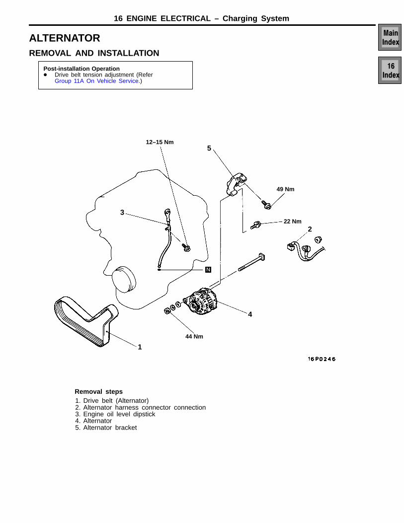
ALTERNATORREMOVAL AND INSTALLATION
Post-installation Operation Drive belt tension adjustment (Refer
Disassembly steps1. Voltage regulator retaining screws
A 2. Voltage regulator3. Suppressor retaining nut4. Suppressor5. B+ terminal nut and washers6. Through bolts7. Slip ring end housing and stator
assembly8. Rectifier assembly retaining nuts
B 9. Stator assembly10. Pulley retaining nut11. Pulley
12. Drive end bearing retaining platescrews
13. Drive end plate14. Drive end bearing15. Bearing retaining plate16. Rotor17. Slip ring end housing bearing18. Slip ring end housing bearing cap19. Rectifier assembly20. Bush21. Slip ring assembly22. Cooling fans
DISASSEMBLY SERVICE POINTSAVOLTAGE REGULATOR REMOVALTilt the regulator slightly from the plug connection until theregulator clears the housing then lift clear.
Caution:Never remove regulator with B+ cable still connectedas alternator rectifier will be damaged.
16 ENGINE ELECTRICAL – Charging System
BSTATOR REMOVALWhen removing stator, unsolder the stator leads solderedto main diodes on rectifier.
Caution1. When soldering or unsoldering, use care to make
sure that heat of soldering iron in not transmittedto diodes for a long period. Finish soldering orunsoldering in as short a time as possible.
2. Use care that no undue force is exerted to leadsof diodes.
INSPECTIONROTOR1. Check rotor coil for continuity. Check to ensure that there
is continuity between slip rings. If resistance is too small,it means that there is a short circuit. If there is no continuityor if there is a short circuit, replace rotor assembly.
Resistance value: Approx. 2.6 Ω2. Check rotor coil for grounding. Check to ensure that there
is no continuity between slip ring and core. If there iscontinuity, replace rotor assembly.
DIODE CONNECTIONS
Diode Diode
Housing(Anode)
Housing(Cathode)
Current blockedCurrent flow
Connection(Anode)
Connection(Cathode)
16 ENGINE ELECTRICAL – Charging System
STATOR1. Make continuity test on stator coil. Check to ensure that
there is continuity between coil leads. If there is no conti-nuity, replace stator assembly.
2. Check coil for grounding. Check to ensure that thereis no continuity between coil and core. If there is continuity,replace stator assembly.
POWER DIODES1. Apply the negative test probe of the diode tester or a
multimeter with a diode test feature to the positive heatsinkand the positive probe alternatively to A, B and C, alow resistance reading, or the forward voltage drop acrossthe diode should be obtained. Reverse the test probes,a high resistance reading or a higher reverse voltageshould be obtained.
2. Connect the positive test probe to the negative heatsinkand the negative test probe alternatively to D, E andF, a low resistance of forward voltage drop across thediode should be obtained. Reverse the test probes, ahigh resistance reading or higher reverse voltage readingshould be obtained.
BRUSHES1. Ensure the brushes have not been worn to or beyond
their wear limit,
Brush wear limit: 3.8mm2. Check the brush springs for burning and loss of tension
due to excessive heat.
SLIP RINGS1. Check the slip rings for excessive wear and damage.
Minimum slip ring diameter: 26.7mm
DIODE CONNECTIONS
Diode Diode
Housing(Anode)
Housing(Cathode)
Current blockedCurrent flow
Connection(Anode)
Connection(Cathode)
A
B
C
GH
D
E
F
16 ENGINE ELECTRICAL – Starting System
STARTING SYSTEMGENERAL INFORMATIONIf the ignition switch is turned to the “START” posi-tion, current flows in the coil provided inside magnet-ic switch, attracting the plunger. When the plungeris attracted, the lever connected to the plungeris actuated to engage the starter clutch.Attracting the plunger will turn on the magneticswitch, allowing the B terminal and M terminal toconduct. Thus, current flows to engage the startermotor.
When the ignition switch is returned to the “ON”position after starting the engine, the starter clutchis disengaged from the ring gear.An overrunning clutch is provided between thepinion and the armature shaft, to prevent damageto the starter.
Battery
Ignition switch
Pull-in coil Hold-in coilPlunger
Armature
Brush Yoke
Lever
Overrunningclutch
Pinion
Reduction drive unit
B
M
S
STARTER MOTOR SPECIFICATIONS
Items
Type Reduction drive with planetary gearRated output kW/V 1.4/12No. of pinion teeth 8
16 ENGINE ELECTRICAL – Starting System
SERVICE SPECIFICATIONS
Items Standard value Limit
Free running Terminal voltage V 12 ± 0.1 –
Free running Current A 65 –characteristics Speed r/min 3,300 or more –Commutator run out mm 0.10 –Commutator diameter mm 32.3 31.2Undercut depth mm 0.8 –
16 ENGINE ELECTRICAL – Starting System
STARTER MOTORREMOVAL AND INSTALLATION
Pre-removal and Post-installation OperationAir Cleaner Removal and Installation
2
131 Nm
131 Nm
Removal steps1. Bolt2. Starter motor
16 ENGINE ELECTRICAL – Starting System
MAGNETIC SWITCH PULL-IN TEST1. Disconnect field coil wire from M-terminal of magnetic
switch.2. Connect a 12V battery between S-terminal and M-termi-
nal.
CautionThis test must be performed quickly (in less than10 seconds) to prevent coil from burning.
3. If pinion moves out, then pull-in coil is good. If it doesn’t,replace magnetic switch.
MAGNETIC SWITCH HOLD-IN TEST1. Disconnect field coil wire from M-terminal of magnetic
switch.2. Connect a 12V battery between S-terminal and body.
CautionThis test must be performed quickly (in less than10 seconds) to prevent coil from burning.
3. If pinion remains out, everything is in order. If pinion movesin, hold-in circuit is open. Replace magnetic switch.
FREE RUNNING TEST1. Place starter motor in a vice equipped with soft jaws
and connect a fully-charged 12-volt battery to starter motoras follows:
2. Connect a test ammeter (130-ampere scale) and carbonpile rheostat in series between battery positive post andstarter motor terminal.
3. Connect a voltmeter (15-volt scale) across starter motor.4. Rotate carbon pile to full-resistance position.5. Connect battery cable from battery negative post to starter
motor body.6. Adjust the rheostat until the battery voltage shown by
the voltmeter is 11V.7. Confirm that the maximum amperage is within the speci-
fications and that the starter motor turns smoothly andfreely.
Current: Max. 110 Amps
MAGNETIC SWITCH RETURN TEST1. Disconnect field coil wire from M-terminal of magnetic
switch.2. Connect a 12V battery between M-terminal and body.
CautionThis test must be performed quickly (in less than10 seconds) to prevent coil from burning.
3. Pull pinion out and release. If pinion quickly returns toits original position, everything is in order. If it doesn’t,replace magnetic switch.
Field coil wire
12V
S
Field coil wire
12V
Startermotor
Carbon-pile rheostat
Ammeter
Voltmeter
Battery12V
12V
Field coil wire
16 ENGINE ELECTRICAL – Starting System
STARTER MOTORDISASSEMBLY AND REASSEMBLY
1
16
14
13
2
11
12
1718
15
4
10
98 7 6
5
3
Disassembly steps1. Screw
A 2. Magnetic switch3. Spring4. Solenoid barrel5. End cover screws6. End cover7. C clip8. Flat washer9. Through bolts
DISASSEMBLY SERVICE POINTSAMAGNETIC SWITCH REMOVAL1. Disconnect the field coil wire from terminal M of the
magnetic switch.
BBRUSH HOLDER REMOVAL1. Mark the position of the brush holder in relation to the
yoke assembly.2. Prise back the brush retaining lugs of the brushes which
are connected to the yoke assembly and remove thebrush plate.
CSNAP RING AND STOP RING REMOVAL1. Press the stop ring, by using an appropriate socket
wrench, to the snap ring side.
2. After removing the snap ring (by using snap-ring pliers),remove the stop ring and the overrunning clutch.
STARTER MOTOR PART CLEANING1. Do not immerse parts in cleaning solvent. Immersing the
yoke and field assembly and/or armature will damageinsulation. Wipe these parts with a cloth only.
2. Do not immerse drive unit in cleaning solvent. Overrunningclutch is pre-lubricated at the factory and solvent will washlubrication from clutch.
3. The drive unit may be cleaned with a brush moistenedwith cleaning solvent and wiped dry with a cloth.
Magneticswitch S terminal
B terminal
M terminal
Fieldcoilwire
Stop ring
Socket
Pinion gear
Overrunningclutch
Armature
Snap ring
Pinion gear
Overrunningclutch
Snap-ring pliers
Armature
16 ENGINE ELECTRICAL – Starting System
REASSEMBLY SERVICE POINTASTOP RING AND SNAP RING INSTALLATIONUsing a suitable pulling tool, pull the overrunning clutch stopring over the snap ring.
BGEAR SET HOUSING INSTALLATIONEnsure the flat of the gear set housing and the flat of thefront housing are aligned together.
INSPECTIONCOMMUTATOR1. Place the armature on a pair of V-blocks, and check the
deflection by using a dial gauge.
Standard value: 0.05 mmLimit: 0.1 mm
2. Check the outer diameter of the commutator.
Standard value: 32.3 mmLimit: 31.2 mm
3. Check the depth of the undercut between segments.
Standard value: 0.8 mm
Snap ring
Stop ringOverrunningclutch
Stop ring
Gear set andfront housingflat section
Mica
Segment
Undercut
16 ENGINE ELECTRICAL – Starting System
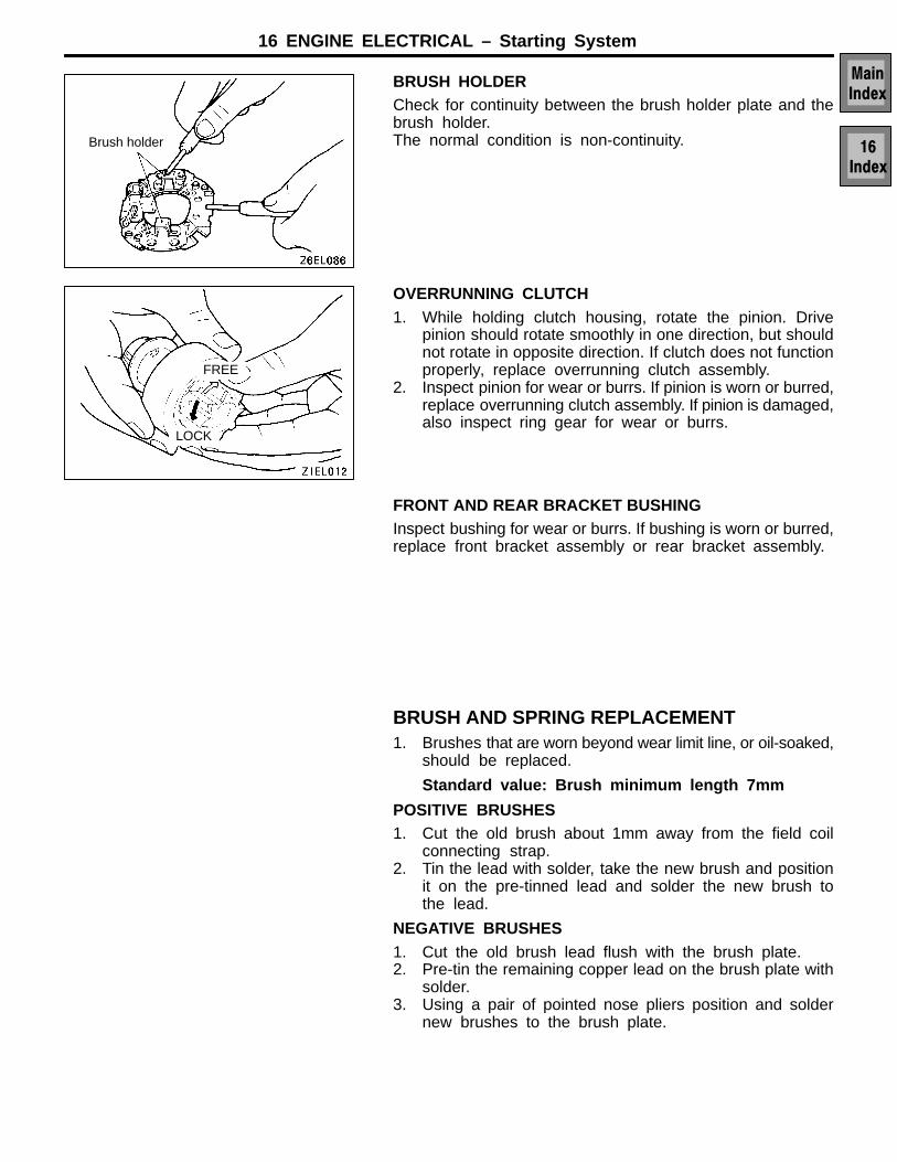
BRUSH HOLDERCheck for continuity between the brush holder plate and thebrush holder.The normal condition is non-continuity.
OVERRUNNING CLUTCH1. While holding clutch housing, rotate the pinion. Drive
pinion should rotate smoothly in one direction, but shouldnot rotate in opposite direction. If clutch does not functionproperly, replace overrunning clutch assembly.
2. Inspect pinion for wear or burrs. If pinion is worn or burred,replace overrunning clutch assembly. If pinion is damaged,also inspect ring gear for wear or burrs.
FRONT AND REAR BRACKET BUSHINGInspect bushing for wear or burrs. If bushing is worn or burred,replace front bracket assembly or rear bracket assembly.
BRUSH AND SPRING REPLACEMENT1. Brushes that are worn beyond wear limit line, or oil-soaked,
should be replaced.
Standard value: Brush minimum length 7mm
POSITIVE BRUSHES1. Cut the old brush about 1mm away from the field coil
connecting strap.2. Tin the lead with solder, take the new brush and position
it on the pre-tinned lead and solder the new brush tothe lead.
NEGATIVE BRUSHES1. Cut the old brush lead flush with the brush plate.2. Pre-tin the remaining copper lead on the brush plate with
solder.3. Using a pair of pointed nose pliers position and solder
new brushes to the brush plate.
Brush holder
LOCK
FREE
16 ENGINE ELECTRICAL – Starting System
ARMATURE TESTARMATURE SHORT-CIRCUIT TEST1. Place armature in a growler.2. Hold a thin steel blade parallel and just above while rotating
the armature slowly. A shorted armature will cause theblade to vibrate and be attracted to the core. Replacea shorted armature.
ARMATURE COIL GROUND TESTCheck the insulation between the armature coil cores andthe commutator segments. They are normal if there is nocontinuity.
ARMATURE COIL OPEN-CIRCUIT TESTCheck for continuity between segments. The condition is nor-mal if there is continuity.
Growler
16 ENGINE ELECTRICAL – Ignition System
IGNITION SYSTEMGENERAL INFORMATIONInterruption of the primary current flowing in theprimary side of the ignition coil generates high vol-tage in the secondary side of the ignition coil. Thehigh voltage thus generated is directed by the distri-butor to the applicable spark plug. The engine firingorder is 1–2–3–4–5–6 cylinders.On application of high voltage, the spark plug gener-ates a spark to ignite the compressed air fuel mixturein the combustion chamber.The Engine A/T-ECU makes and breaks the primarycurrent of the ignition coil to regulate the ignitiontiming.
The Engine A/T-ECU detects the crankshaft posi-tion by the crank angle sensor mounted on theengine to provide ignition at the most appropriatetiming for the engine operating condition.When the engine is cold or operated at a highaltitude, the ignition timing is slightly advanced toprovide optimum performance to the operatingcondition.When the automatic transmission shifts gears, igni-tion timing is retarded to reduce output torque andalleviate shock during shifting.
Air flow sensor
Intake air temperature sensor
Engine coolant temperaturesensor
Idle position switch
Vehicle speed sensor
Inhibitor switch
Ignition switch-(ST)
Engine-A/T-ECU
Camshaftpositionsensor
Powertransistor
To tachometer
Distributor
Spark plug
Ignitionswitch
Battery
Engine-ECU
Crank angle sensorA/T-ECU
16 ENGINE ELECTRICAL – Ignition System
DISTRIBUTOR SPECIFICATIONS
Items
Type Contact pointless with built-in ignition coil and powertransistor
Advance mechanism ElectronicFiring order 1–2–3–4–5–6
IGNITION COIL SPECIFICATION
Items
Type Moulded single-coil incorporated in distributor
ON-VEHICLE SERVICESPARK PLUG CABLE TEST1. Disconnect, one at a time, each of the spark plug cables
while the engine is idling to check whether the engine’srunning performance changes or not.
CautionWear rubber gloves while doing so.
2. If the engine performance does not change, check theresistance of the spark plug cable, and check the sparkplug itself.
SPARK PLUG TEST1. Remove the spark plug and connect to the spark plug
cable.Caution
Inhibit engine starting2. Ground the spark plug outer electrode (body), and crank
the engine.Check to be sure that there is an electrical dischargebetween the electrodes at this time.
IGNITION COIL CHECK1. Measurement of the primary coil resistance
Measure the resistance between connector terminal 1and 2 of the distributor.
Standard value: 0.5–0.7Ω
2. Measurement of secondary coil resistanceMeasure the resistance between the high-voltage termi-nals and connector terminals 1 or 2.
Standard value: 9–13 kΩ
Spark plug cable
Spark plug
Defective insulationDefective insulation
GoodDefective insulation
Hightensionterminal
16 ENGINE ELECTRICAL – Ignition System
POWER TRANSISTOR CHECK
NOTEAn analog-type ohmmeter should be used.
1. Connect the negative (–) terminal of the 1.5V power supplyto terminal 4 of the power transistor; then check whetherthere is continuity between terminal 4 and terminal 2 whenterminal 3 and the positive (+) terminal are connectedand disconnected.
NOTEConnect the negative (–) probe of the circuit tester toterminal 12.
Terminal 6 and (+) terminal Terminal 5 and terminal 12
Connected Continuity
Unconnected No continuity
2. Replace the power transistor if there is a malfunction.
SPARK PLUG CABLE RESISTANCE CHECK
Measure the resistance of all spark plug leads.1. Check cap and coating for cracks.2. Measure resistance
Limit: Max. 22 kΩ
Distributor connector
1.5V+ –
+–
16 ENGINE ELECTRICAL – Ignition System
SPARK PLUG CHECK AND CLEANING1. Remove the engine cover and intake manifold plenum,
refer Group 11B On Vehicle Service.2. Remove the spark plug cables.
CautionWhen pulling off the spark plug cable from the plugalways hold the cable cap, not the cable.
3. Remove the spark plugs.4. Check for burned out electrode or damaged insulator.
Check for even burning.5. Remove carbon deposits with a plug cleaner. Remove
sand from plug screw with compressed air.
CautionWhen cleaning platinum tip spark plugs the tip maybe damaged. If carbon deposits must be removeduse a plug cleaner and complete cleaning within 20seconds. Do not use a wire brush.
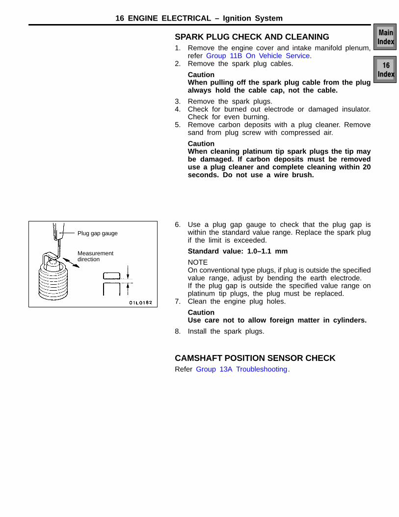
6. Use a plug gap gauge to check that the plug gap iswithin the standard value range. Replace the spark plugif the limit is exceeded.
Standard value: 1.0–1.1 mm
NOTEOn conventional type plugs, if plug is outside the specifiedvalue range, adjust by bending the earth electrode.If the plug gap is outside the specified value range onplatinum tip plugs, the plug must be replaced.
7. Clean the engine plug holes.
CautionUse care not to allow foreign matter in cylinders.
8. Install the spark plugs.
CAMSHAFT POSITION SENSOR CHECKRefer Group 13A Troubleshooting.
Plug gap gauge
Measurementdirection
16 ENGINE ELECTRICAL – Ignition System
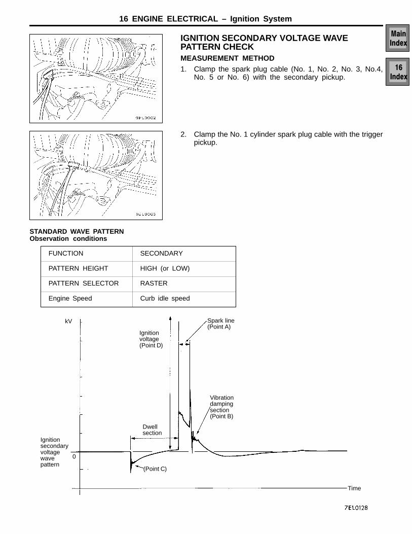
IGNITION SECONDARY VOLTAGE WAVEPATTERN CHECKMEASUREMENT METHOD1. Clamp the spark plug cable (No. 1, No. 2, No. 3, No.4,
No. 5 or No. 6) with the secondary pickup.
2. Clamp the No. 1 cylinder spark plug cable with the triggerpickup.
STANDARD WAVE PATTERNObservation conditions
FUNCTION SECONDARY
PATTERN HEIGHT HIGH (or LOW)
PATTERN SELECTOR RASTER
Engine Speed Curb idle speed
Ignitionvoltage(Point D)
Spark line(Point A)
Vibrationdampingsection(Point B)
Dwellsection
(Point C)
Ignitionsecondaryvoltagewavepattern
Time
kV
0
16 ENGINE ELECTRICAL – Ignition System
WAVEFORM OBSERVATION POINTS
Point A:The height, length and slope of the spark line (refer to abnormal waveform examples 1, 2, 3and 4) show the following trends.
Spark line Plug gap Condition ofelectrode
Compressionforce
Concentration ofair mixture
Ignition tim-ing
Spark plug cable
Length Long Small Normal Low Rich Advanced Leak
Length Short Large Large wear High Lean Retarded High resistance
Height High Large Large wear High Lean Retarded High Resistance
Height Low Small Normal Low Rich Advanced Leak
Slope Large Plug isfouled
– – – –
Point B:Number of vibration in reduction vibration section(Refer to abnormal waveform example 5.)
Number of vibrations Coil and condenser
Three or more Normal
Except above Abnormal
Point C:Number of vibrations at beginning of dwell section(Refer to abnormal waveform example 5.)
Number of vibrations Coil
5–6 or higher Normal
Except above Abnormal
Point D:Ignition voltage height (distribution per each cylinder) shows the following trends.
Ignitionvoltage
Plug gap Condition ofelectrode
Compressionforce
Concentration ofair mixture
Ignition timing Spark plugcable
High
Low
Large
Small
Large wear
Normal
High
Low
Lean
Rich
Retarded
Advanced
High resistance
Leak
16 ENGINE ELECTRICAL – Ignition System
ABNORMAL WAVEFORMS EXAMPLES
Abnormal waveform Wave characteristics Cause of problem
Example 1 Spark line is high and short. Spark plug gap is too large.
Example 2 Spark line is low and long, and issloping.
Also, the second half of the sparkline is distorted. This could be a re-sult of misfiring.
Spark plug gap is too small.
Example 3 Spark line is low and long, and issloping. However, there is almostno spark line distortion.
Spark plug gap is fouled.
Example 4 Spark line is high and short.
Difficult to distinguish between thisand abnormal wave pattern exam-ple 1.
Spark plug cable is nearly falling off.(Causing a dual ignition)
Example 5 No waves in wave damping section Rare short in ignition coil.
16 ENGINE ELECTRICAL – Ignition System
IGNITION PRIMARY VOLTAGE WAVE PATTERNCHECKMEASUREMENT METHOD1. Disconnect the distributor connector and connect the spe-
cial tool (test harness: EMB991348) in between. (All ofthe terminals should be connected.)
2. Connect the analyser primary pickup to the distributorconnector terminal 2.
3. Connect the primary pickup earth terminal.4. Clamp the spark plug cable with the trigger pickup.
NOTEThe wave pattern of the cylinder clamped to the triggerpickup will appear at the left edge of the screen.
Analyser
Primarypickup
Ground
16 ENGINE ELECTRICAL – Ignition System
STANDARD WAVE PATTERNObservation conditions
FUNCTION SECONDARY
PATTERN HEIGHT HIGH (or LOW)
PATTERN SELECTOR RASTER
Engine Speed Curb idle speed
Zenervoltage(Point C)
(Approx.40×10V)
Spark line(Point A)
Dwellsection
Vibrationdampingsection(Point B)
Ignitionprimaryvoltagewavepattern
Time
(V)
100
0
Observation conditions(Only the pattern selector shown below changes from the previous conditions)
Ignitionprimaryvoltagewavepattern
Centresection
Time
(V)
100
0
PATTERN SELECTOR DISPLAY
16 ENGINE ELECTRICAL – Ignition System
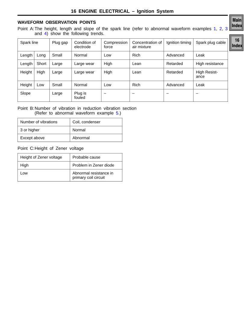
WAVEFORM OBSERVATION POINTSPoint A:The height, length and slope of the spark line (refer to abnormal waveform examples 1, 2, 3
and 4) show the following trends.
Spark line Plug gap Condition ofelectrode
Compressionforce
Concentration ofair mixture
Ignition timing Spark plug cable
Length Long Small Normal Low Rich Advanced Leak
Length Short Large Large wear High Lean Retarded High resistance
Height High Large Large wear High Lean Retarded High Resist-ance
Height Low Small Normal Low Rich Advanced Leak
Slope Large Plug isfouled
– – – –
Point B:Number of vibration in reduction vibration section(Refer to abnormal waveform example 5.)
Number of vibrations Coil, condenser
3 or higher Normal
Except above Abnormal
Point C:Height of Zener voltage
Height of Zener voltage Probable cause
High Problem in Zener diode
Low Abnormal resistance inprimary coil circuit
16 ENGINE ELECTRICAL – Ignition System
ABNORMAL WAVEFORMS EXAMPLES
Abnormal waveform Wave characteristics Cause of problem
Example 1 Spark line is high and short. Spark plug gap is too large.
Example 2 Spark line is low and long, and issloping.
Also, the second half of the sparkline is distorted. This could be a re-sult of misfiring.
Spark plug gap is too small.
Example 3 Spark line is low and long, and issloping. However, there is almostno spark line distortion.
Spark plug gap is fouled.
Example 4 Spark line is high and short. Spark plug cable is nearly falling off.(Causing a dual ignition)
Example 5 No waves in wave damping section Rare short in ignition coil.
16 ENGINE ELECTRICAL – Ignition System
IGNITION SYSTEMREMOVAL AND INSTALLATION
Pre-removal and Post-installation OperationEngine cover removal and installation (ReferGroup 11B On Vehicle Service.)
1
4
3
2
23 Nm
25 Nm1
Removal stepsB 1. Spark plug cable
2. Spark plugA 3. Distributor
4. O-ring
16 ENGINE ELECTRICAL – Ignition System
INSTALLATION SERVICE POINTSADISTRIBUTOR INSTALLATION1. Turn the crankshaft so that the No. 1 cylinder is at top
dead centre.2. Align the distributor housing and gear mating marks and
install the distributor.
BSPARK PLUG CABLEImproper arrangement of spark plug cables will induce voltagebetween the cables, causing misfiring and developing a surgeat acceleration in high-speed operation.Therefore, be careful to arrange the spark plug cables properlypaying attention to the following items.1. Install the cables securely to avoid possible contact with
metal parts.2. Install the cables neatly, ensuring they are not too tight,