40
Prof. B V S Viswanadham, Department of Civil Engineering, IIT Bombay 17

Prof. B V S Viswanadham, Department of Civil Engineering, IIT Bombay
17
Prof. B V S Viswanadham, Department of Civil Engineering, IIT Bombay
Permeability and Seepage -6

Prof. B V S Viswanadham, Department of Civil Engineering, IIT Bombay
Flow net construction for an earth dam
H1
H2
A
B
CD
E
AE – Flow line; AB – Eqp. Line with head H1;
DE -Eqp. Line with head H2; BC – flow line ( or phreatic surface);
CD – neither a flow line nor an eqp. line (component of flow normal to CD ad water flows freely down the surface of the slope).

Prof. B V S Viswanadham, Department of Civil Engineering, IIT Bombay
Embankment with permeable filter
H
A
a
0.3∆
d
∆H
pp∆
a′Basic parabola
β = 180; ∆l/(l+∆l) = 0
EQP. Line with zero head

Prof. B V S Viswanadham, Department of Civil Engineering, IIT Bombay
Seepage through homogeneous sand beneath base of concrete dams
Prof. B V S Viswanadham, Department of Civil Engineering, IIT Bombay
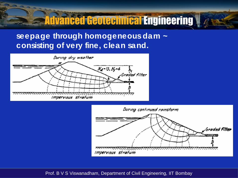
seepage through homogeneous dam ~consisting of very fine, clean sand.

Prof. B V S Viswanadham, Department of Civil Engineering, IIT Bombay
Filter designWhen seepage water flows from a soil with relativelyfine grains into a coarser material, there is a dangerthat the fine soil particles may wash away into thecoarse material.
Such a situation can be prevented by the use of afilter or protective filter between the two soils.

Prof. B V S Viswanadham, Department of Civil Engineering, IIT Bombay
Typical flow net for an earthdam with rock toe filterWithout filter at the toe, the seepage water would wash the finesoil grains into the toe and undermine the structure.
For FOS

Prof. B V S Viswanadham, Department of Civil Engineering, IIT Bombay
Typical flow net for an earth dam withchimney drain

Prof. B V S Viswanadham, Department of Civil Engineering, IIT Bombay
Filter design
1) The size of the voids in the filter material should besmall enough to hold the larger particles of theprotected material in place.
2) The filter material should have a high permeabilityto prevent buildup of large seepage forces andhydrostatic pressure in the filters.
For the proper selection of the filter material,
54)
)(85
(15 −≤S
F
dd
54)
)(15
(15 −≥S
F
dd
d15(F) = Dia. Through which 15% of filter materialwill pass
d85(S) = Dia. Through which 85% of soil to be protectedwill pass
d15(S) = Dia. Through which 15% of soil to beprotected will pass

Prof. B V S Viswanadham, Department of Civil Engineering, IIT Bombay
Earthen dam section without any drainage (or with clogged drain)
6 m
30g

Prof. B V S Viswanadham, Department of Civil Engineering, IIT Bombay
Numerical simulation of Earthen dam section without any drainage
(or with clogged drain)

Prof. B V S Viswanadham, Department of Civil Engineering, IIT Bombay
Transient seepage analysis duration-30 days (SEEP/W)

Prof. B V S Viswanadham, Department of Civil Engineering, IIT Bombay
Earthen dam section with horizontal sand drain of 0.6 m thickness
6 m
30g

Prof. B V S Viswanadham, Department of Civil Engineering, IIT Bombay
Transient seepage analysis duration-30 days (SEEP/W)

Prof. B V S Viswanadham, Department of Civil Engineering, IIT Bombay
Numerical simulation of Earthen dam section with horizontal sand drain of
0.6 m thickness

Prof. B V S Viswanadham, Department of Civil Engineering, IIT Bombay
For a single row of sheet pile structure, draw a flownet diagram, given that:
a) the soil is isotropic, with permeability of 0.001m/sec.b) the soil is anisotropic with ratio of permeabilitiesas kx=6kz
Example Problem:

Prof. B V S Viswanadham, Department of Civil Engineering, IIT Bombay
FEM mesh of the sheet pile section

Prof. B V S Viswanadham, Department of Civil Engineering, IIT Bombay
Case a: Isotropicsection. Note that theflow and equipotentiallines are orthogonal inthis case.

Prof. B V S Viswanadham, Department of Civil Engineering, IIT Bombay
Case b: Anisotropicsection. Note that theflow and equipotentiallines are not orthogonalin this case.

Prof. B V S Viswanadham, Department of Civil Engineering, IIT Bombay
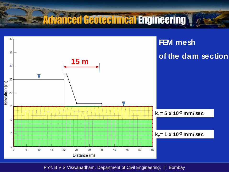
Construct a flow net for the dam section resting ona two layered soil deposit with k1= 5 x 10⁻²
mm/sec and k2 = 1 x 10⁻² mm/sec. Hencecomment on the results obtained.
Example problem:
Prof. B V S Viswanadham, Department of Civil Engineering, IIT Bombay
k1= 5 x 10⁻² mm/sec
k2= 1 x 10⁻² mm/sec
FEM mesh
of the dam section15 m

Prof. B V S Viswanadham, Department of Civil Engineering, IIT Bombay
Note: Since k1/k2 =5,the length-to-widthratio of the flowelements in layer 2with respective tolayer 1 is 1/5.
l2/b2 = 1/5 with b1/l1 = 1

Prof. B V S Viswanadham, Department of Civil Engineering, IIT Bombay
Drop in pressure head along the length of thedam due to seepage losses

Prof. B V S Viswanadham, Department of Civil Engineering, IIT Bombay
Construct the flow nets for the dam sections shown,given that:
a) the soil is isotropic, with permeability of 5 x 10⁻⁵
m/sec
b) the dam is zoned with k2 = 5k1
Example problem:

Prof. B V S Viswanadham, Department of Civil Engineering, IIT Bombay
Case a: Homogeneous dam; k = 5 x 10⁻⁵ m/sec

Prof. B V S Viswanadham, Department of Civil Engineering, IIT Bombay
Solution for Case a:
fd
NNhkq =
Nf = 2.5; Nd = 10

Prof. B V S Viswanadham, Department of Civil Engineering, IIT Bombay
Case b) Zoned dam

Prof. B V S Viswanadham, Department of Civil Engineering, IIT Bombay
Flow net for seepage through a zoned earth dam
The soil for the upstream half of the dam has apermeability k1, and the soil for the downstream halfof the dam has a permeability k2 = 5 k1.
Square elementsl1 = b1
k1
k2
α1
α2
k1 < k2
b2/l2 <1
Using
For k1/k2 = 5 b2/l2 = 1/5b2
l2

Prof. B V S Viswanadham, Department of Civil Engineering, IIT Bombay
Solution for Case b:
k1
k2 = 5 k1
Nf1 = Number of full flow channels in soil 1 with k1 = 2 +2/3
11
2/3
1/51/5
2/15
Nf2 = Number of full flow channels in soil 2 with k2 = 8/15
Nd = 10
2211 fd
fd
NNhkN
Nhkq ==

Prof. B V S Viswanadham, Department of Civil Engineering, IIT Bombay
Failure due to piping for single row of sheet-pile wall structure (Terzaghi, 1922)By considering a soil prismon the downstream side ofunit thickness and ofsection D x D/2Using the flow net the hydraulic uplift pressure can be determined as:
mwDhU γ21
=2
BAm
hhh += hA
hBhm = Avg. hydraulic head at the base of the soil prism
2
21 DW γ ′=′

Prof. B V S Viswanadham, Department of Civil Engineering, IIT Bombay
Failure due to piping for single row of sheet-pile wall structureFOS against heave(or piping) is wm
mwhD
Dh
D
UWFOS
γγ
γ
γ ′=
′=′
=
2121 2
m
c
iiFOS =
eGi s
wc +
−=
′=
11
γγ∴≈ 4
Dhi m
m =To find hm – Find the total head within D/2 zone horizontally

Prof. B V S Viswanadham, Department of Civil Engineering, IIT Bombay
For structures other than a single row of sheet pile walls
Terzaghi (1943) recommendedthat D/2 x D′X1
0 < D′ ≤ D

Prof. B V S Viswanadham, Department of Civil Engineering, IIT Bombay
Safety of hydraulic structures against piping
According to Harza (1935)
exit
c
iiFOS =
iexit = maximum hydraulic gradient
lhiexit
∆= From flow net
=
DHiexit π
1 According to Harr (1962)H = Maximum hydraulic head;
D = Depth of penetration of sheet pile wall

Prof. B V S Viswanadham, Department of Civil Engineering, IIT Bombay
Safety of hydraulic structures against piping
maximum hydraulic gradient

Prof. B V S Viswanadham, Department of Civil Engineering, IIT Bombay
Example problem
A stiff clay layer underlies a 12 m thick silty sanddeposit. A sheet pile is driven into the sand to a depthof 7 m. k of silty sand is 8 x 10⁻⁶ m/s. The stiff clay canbe assumed to be impervious. e of silty sand is 0.72and Gs = 2.65
a) Draw the flow net and estimate Q
b) What is the PWP at the tip of the sheet pile wall
c) FOS against piping failure?

Prof. B V S Viswanadham, Department of Civil Engineering, IIT Bombay
3 m
2 m
7 m
5 m
Silty sand
Stiff clay
Example problem

Prof. B V S Viswanadham, Department of Civil Engineering, IIT Bombay
Example problem
2 m8
65
3
0
Prof. B V S Viswanadham, Department of Civil Engineering, IIT Bombay
Example problem
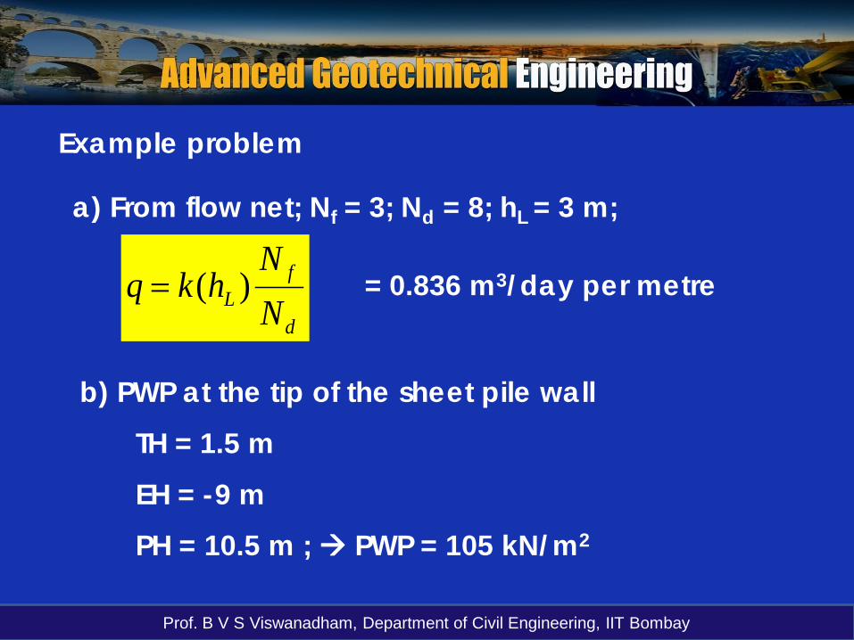
a) From flow net; Nf = 3; Nd = 8; hL = 3 m;
d
fL N
Nhkq )(= = 0.836 m3/day per metre
b) PWP at the tip of the sheet pile wall
TH = 1.5 m
EH = -9 m
PH = 10.5 m ; PWP = 105 kN/m2

Prof. B V S Viswanadham, Department of Civil Engineering, IIT Bombay
Example problem
c) Head loss per EQP drop ∆h = 3/8 = 0.375 m
Max. exit hydraulic gradient = 0.375/2.6 = 0.144
ic = (2.65-1)/(1 + 0.72) = 0.96
exit
c
iiFOS = = 0.96/0.144 = 6.7 > 5
The arrangement is quite safe with respect to piping failure


