68
EK210 State Volume Corrector EK210 Operating Manual and Installation Instructions Operating Manual 73017449 SW version: from V 1.21 Issued: 19.04.2004 (d) Edition:

EK210
State Volume Corrector EK210 Operating Manual and Installation Instructions
Operating Manual 73017449 SW version: from V 1.21 Issued: 19.04.2004 (d) Edition:
Electronic Volume Corrector EK210
2 ELSTER Handel GmbH
All rights reserved. Copyright © 2004 ELSTER Handel GmbH, D-55252 Mainz-Kastel All the figures and descriptions in this operating and instruction manual have been compiled only after careful checking. Despite this however, the possibility of errors cannot be completely eliminated. Therefore, no guarantee can be given for completeness or for the content. Also, the manual cannot be taken as giving assurance with regard to product characteristics. Furthermore, characteristics are also described in it that are only available as options. The right is reserved to make changes in the course of technical development. We would be very grateful for suggestions for improvement and notification of any errors, etc. With regard to extended product liability the data and material characteristics given should only be taken as guide values and must always be individually checked and corrected where applicable. This particularly applies where safety aspects must be taken into account. Passing this manual to third parties and its duplication, in full or in part, are only allowed with written permission from ELSTER Handel GmbH. Mainz-Kastel, April 2004

Electronic Volume Corrector EK210
ELSTER HANDEL GmbH 3
Contents I Safety information ........................................................................................5
II Items supplied and accessories...................................................................6
1 Brief description ...........................................................................................7
2 Operation......................................................................................................9 2.1 Front panel ..................................................................................................... 9 2.2 Display............................................................................................................ 9
2.2.1 Line 1 = Labels....................................................................................... 10 2.2.2 Line 2 = Value with name and unit ......................................................... 10
2.3 Keypad ......................................................................................................... 11 2.3.1 Changing values..................................................................................... 12 2.3.2 Entering "sources".................................................................................. 13 2.3.3 Entry errors............................................................................................. 13
2.4 Access rights ................................................................................................ 14 2.4.1 Calibration lock....................................................................................... 14 2.4.2 Supplier's lock and customer's lock........................................................ 15
2.5 Formation of the list structure ....................................................................... 15
3 Functional description ................................................................................18 3.1 User list......................................................................................................... 19 3.2 Standard volume list ..................................................................................... 20 3.3 Actual volume list.......................................................................................... 21 3.4 Pressure list.................................................................................................. 22 3.5 Temperature list............................................................................................ 24 3.6 Volume corrector list..................................................................................... 26 3.7 Status list ...................................................................................................... 28
3.7.1 Messages in system status (SR.Sy)....................................................... 29 3.7.2 Messages in Status Registers 1 to 9 (SR.1 to SR.9) ............................. 30
3.8 System list .................................................................................................... 36 3.9 Service list .................................................................................................... 38 3.10 Input list ............................................................................................... 40 3.11 Output list............................................................................................. 42
3.11.1 Brief summary of output parameterisation ............................................. 47 3.12 Archives ............................................................................................... 48
3.12.1 Month Archive 1 (counter readings and maxima) .................................. 48 3.12.2 Logbook (event logbook)........................................................................ 48 3.12.3 Changes logbook (audit trail) ................................................................. 48
Electronic Volume Corrector EK210
4 ELSTER Handel GmbH
4 Applications ............................................................................................... 49 4.1 Application in areas subject to explosion hazards ....................................... 49
4.1.1 Applications in Zone 1............................................................................ 49 4.1.2 Applications in Zone 2............................................................................ 49
5 Installation and maintenance .................................................................... 50 5.1 Installation procedure ................................................................................... 50 5.2 Cable connection and earthing..................................................................... 51 5.3 Terminal layout ............................................................................................. 52 5.4 Seals............................................................................................................. 53
5.4.1 Seal layout.............................................................................................. 54 5.5 Battery replacement ..................................................................................... 55
5.5.1 Carrying out battery replacement........................................................... 56
A Approvals................................................................................................... 57 A.1 EC Declaration of Conformance.......................................................... 57 A.2 Approval for Ex Zone 1........................................................................ 59
B Technical data ........................................................................................... 63 B-1 General data (mechanical)............................................................................. 63 B-2 Battery ................................................................................................. 63 B-3 Pulse and status inputs ....................................................................... 64 B-4 Signal and pulse outputs ..................................................................... 64 B-5 Optical serial interface ......................................................................... 65 B-6 Pressure sensor .................................................................................. 65 B-7 Temperature sensor ............................................................................ 66
B-7.1 Temperature sensor Pt500 / EBL160KF ................................................ 66 B-7.2 Temperature sensor Pt500 / EBL50KF .................................................. 67
B-8 Measurement uncertainty .................................................................... 67
C Index.......................................................................................................... 68
Electronic Volume Corrector EK210
ELSTER HANDEL GmbH 5
I Safety information F The connections of the EK210 are freely accessible during setting up. Therefore, make
sure that no electrostatic discharge (ESD) can occur in order to avoid damage to the components. The person carrying out the installation can, for example, discharge himself/herself by touching the potential equalisation line.
F To avoid erroneous operation and problems, the operating manual must be read before putting the EK210 into operation.
The EK210 Electronic State Volume Corrector is suitable for applications in Ex Zone 1 for gases in the temperature class T4 (ignition temperature > 135°C, e.g. nat ural gas) according to VDE 0170 (see Appendix A-2). In this application it is essential to take note of the following information:
F Follow the regulations in the relevant standards, in particular DIN EN 60079-14 (VDE 0165 Part 1) and DIN EN 50014.
F Make sure that the limits quoted in the certificate of conformance (see Appendix A-2) for the devices to be connected are not exceeded.
F The housing of the EK210 must be earthed directly to a potential equalisation strip. A connection screw is located on the left wall of the housing for this purpose.

Electronic Volume Corrector EK210
6 ELSTER Handel GmbH
II Items supplied and accessories Items supplied: The items supplied with the EK210 include:
a) EK210 Electronic State Volume Corrector b) Dispatch list c) Design data sheet d) Operating Manual e) Bag of accessories
Ordering information and accessories Order no.
• EK210 Electronic State Volume Corrector, complete 83 462 240
• EBL 50 Temperature Sensor Receptacle, complete with M10 x 1 weld-in sleeve
73 012 634
• EBL 67 Temperature Sensor Receptacle, complete with M10 x 1 weld-in sleeve
73 014 456
• EBL 160 Temperature Sensor Receptacle, complete with G 3/4" weld-in sleeve and seal
73 012 100
• EBL 250 Temperature Sensor Receptacle, complete with G 3/4" weld-in sleeve and seal
73 015 695
• Three-way test tap 73 008 403
• Shut-off ball valve with Ermeto 6L test connection 73 016 166
• Minimess test connection 73 016 167
• Operating manual, German 73 017 271
• Operating manual, English 73 017 449
• Operating manual, French 73 017 923
• Plug-in terminal, 2-pole black 04 130 407
• Calibration covering cap 73 016 879
• Battery module, 13 Ah 73 015 774
• Bag of accessories, EK2xx 73 017 991
Electronic Volume Corrector EK210
ELSTER HANDEL GmbH 7
1 Brief description
The EK210 Electronic State Volume Corrector is used for the conversion of the gas volume measured in the operating state by a gas meter to the standard state. The momentary values of pressure and temperature are measured for the determination of the operating state. The gas law deviation value (K factor) can alternatively be calculated according to S-GERG-88 or entered as a constant.
Power supply: • Battery operation with a service life depending on operating mode ≥ 5 years. • Optional double battery life by connection of an additional battery possible. • Battery replacement possible without loss of data and without violation of calibration seals. • Data retention without battery supply due to internal EEPROM.
Operator interface: • Alphanumeric display with two lines of 16 characters. • A display list freely assignable by the user. • Programming via keypad possible. • Calibration switch (separately sealed in the device). • Two user locks (supplier's and customer's locks) with numerical codes. • Access rights for each individual value can be set separately via interface (with appropriate
rights).
Counting / signal inputs: • 3 inputs for reed contacts or transistor switches, programmable as pulse or signal inputs. • Maximum counting frequency 10 Hz. • Pulse value for each input separately adjustable by decade. • Various counters for Vb and V as well as for each input (main counter, disturbance
volumes, totaliser, adjustable counter). • Each input can be separately sealed and secured under official calibration.
Pulse / signal outputs: • 4 programmable transistor outputs, each freely programmable as alarm / warning output,
pulse output, signal output for limit monitoring. • Outputs A1 and A2 can be separately sealed and secured under official calibration.
Data interface: • Optical interface according to IEC 1107.
Pressure sensor: • Type CT30 pressure sensor mounted in device.
Temperature sensor: • Pt500 temperature sensor, types EBL 50 or EBL 160.

Electronic Volume Corrector EK210
8 ELSTER Handel GmbH
Mechanical details / housing: • Suitable for wall mounting and meter and pipe installation (with mounting bracket). • Mounting + device installation without violating the calibration seals. • Ambient temperature range: -20°C...+60°C (with CT30 pressure sensor)
Extended temperature with restricted functions possible.
Approvals: • Calibration approval as electronic state volume corrector, • Ex approval for use in Ex Zone 1 according to EEx ia IIC T4.
Monitoring functions • Monitoring of signalling inputs. • Monitoring of any values against programmable limits. • All monitoring can trigger appropriate reactions such as for example, entries in the status
register, log book or signalling via outputs.
Archive • Counter readings and maxima from the last 15 months for Vb and V • Last month's end value for standard and actual volumes • Event logbook with 250 entries for events such as for example status changes, signalling
inputs, limit violations. • Changes logbook ("audit trail") with entry of the last 200 changes to settings
(parameterising steps). • Automatic summer time changeover can be set.
Electronic Volume Corrector EK210
ELSTER HANDEL GmbH 9
2 Operation
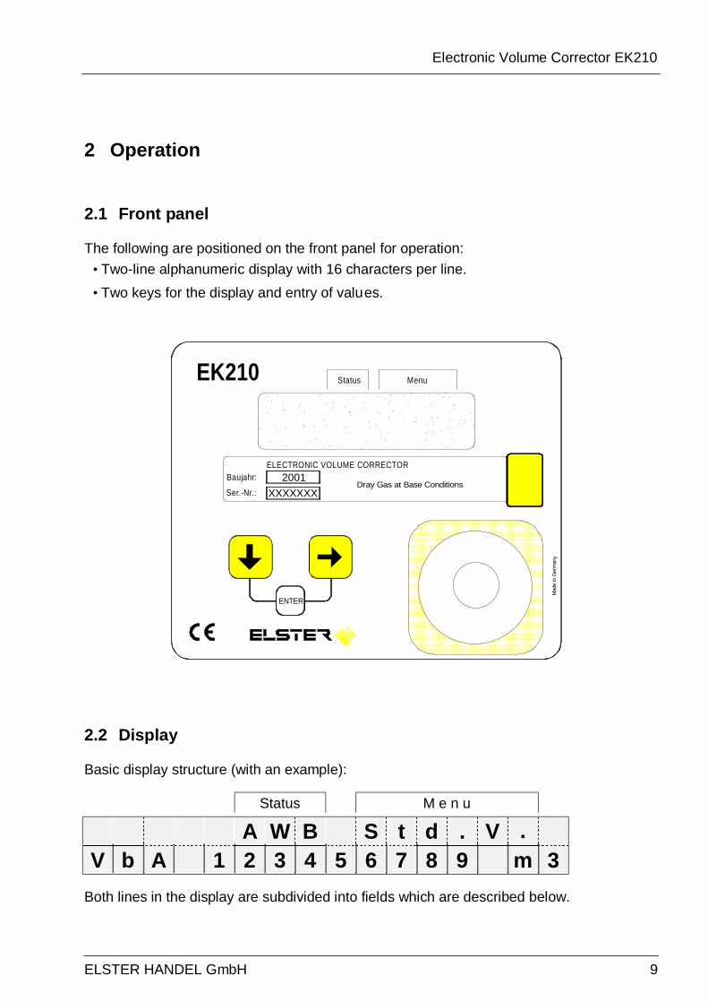
2.1 Front panel
The following are positioned on the front panel for operation: • Two-line alphanumeric display with 16 characters per line. • Two keys for the display and entry of values.
2.2 Display
Basic display structure (with an example):
Status M e n u
A W B S t d . V .
V b A 1 2 3 4 5 6 7 8 9 m 3 Both lines in the display are subdivided into fields which are described below.
ENTER
XXXXXXX2001
ELECTRONIC VOLUME CORRECTORBaujahr:
Ser.-Nr.:
Mad
e in
Ger
man
y
Dray Gas at Base Conditions
EK210 MenuStatus

Electronic Volume Corrector EK210
10 ELSTER Handel GmbH
2.2.1 Line 1 = Labels The first line is subdivided into two fields, both of which are labelled on the front panel.
1. Device status Here a maximum of three of the most important items of status information are continually shown. A flashing label indicates that the corresponding state is still present. A non-flashing character signifies that the corresponding state is past, but the message in the status register has not yet been cleared. Meaning of the letters:
- A "Alarm" At least one status message has occurred which has resulted in disturbance volumes being counted. Basically, all messages "1" and "2" represent alarms (e.g. "Alarm limits for pressure or temperature violated" → 3.7). Alarm messages are copied into the status register and are retained here, even after rectification of the cause of the error, until they are manually cleared.
- W "Warning" At least one status message has occurred which is valid as a warning. Basically, all messages ""3" to "8" represent warnings (e.g. "Error on output" → 3.7). Warning messages are copied into the status register and are retained here, even after rectification of the cause of the error, until they are manually cleared.
- B "Battery discharged" The remaining battery service life is less than 3 months.
- P "Programming mode" The programming lock (calibration lock) is open.
- o "On-line" A data transfer via the optical or permanently wired interface is running. In each case the other interface cannot then be used.
2. Menu Here is displayed to which list according to Chapter 3. The currently displayed value belongs.
2.2.2 Line 2 = Value with name and unit In the second line the name, value and (when available) the unit of the data are always shown. Example:
V b A 1 2 3 4 5 6 7 8 9 m 3

Electronic Volume Corrector EK210
ELSTER HANDEL GmbH 11
2.3 Keypad
Key(s) Designation Effect
Down cursor key
• Downwards movement within the list: From the first value in the list movement is in the direction of the last value or from the last value directly to the first one.
Right cursor key
• Movement to the right to a different list: From the first list movement is in the direction of the last list or from the last list directly to the first one.
• Switchover to the second part of the value for values displayed on two lines: - Counter readings divided into pre- and post-decimal places. - Date and time (together one value) divided.
+ Enter
Depends on the value displayed (Data class, → 2.3.1) • Activate the entry mode. • Terminate entry mode. • Update measurement (by pressing twice).
In the entry mode the keys change their functions, see Chapter 2.3.1.
Electronic Volume Corrector EK210
12 ELSTER Handel GmbH
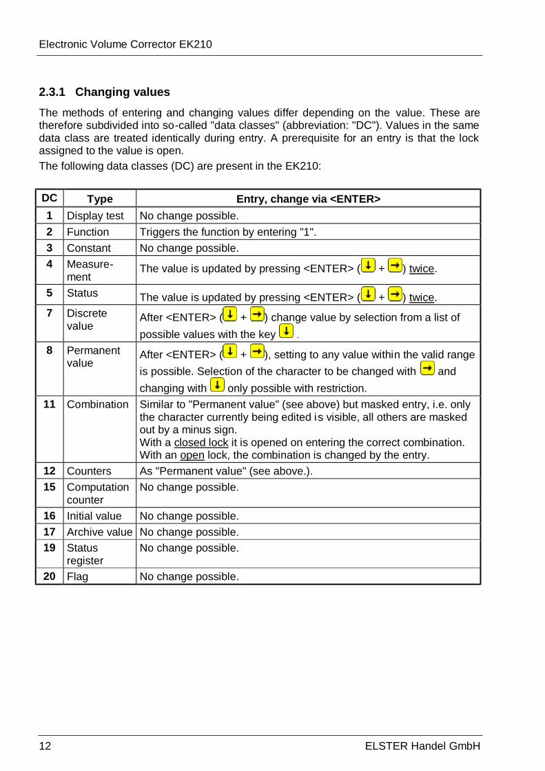
2.3.1 Changing values The methods of entering and changing values differ depending on the value. These are therefore subdivided into so-called "data classes" (abbreviation: "DC"). Values in the same data class are treated identically during entry. A prerequisite for an entry is that the lock assigned to the value is open. The following data classes (DC) are present in the EK210: DC Type Entry, change via <ENTER> 1 Display test No change possible. 2 Function Triggers the function by entering "1". 3 Constant No change possible. 4 Measure-
ment The value is updated by pressing <ENTER> ( + ) twice.
5 Status The value is updated by pressing <ENTER> ( + ) twice. 7 Discrete
value After <ENTER> ( + ) change value by selection from a list of possible values with the key .
8 Permanent value
After <ENTER> ( + ), setting to any value within the valid range is possible. Selection of the character to be changed with and changing with only possible with restriction.
11 Combination Similar to "Permanent value" (see above) but masked entry, i.e. only the character currently being edited is visible, all others are masked out by a minus sign. With a closed lock it is opened on entering the correct combination. With an open lock, the combination is changed by the entry.
12 Counters As "Permanent value" (see above.). 15 Computation
counter No change possible.
16 Initial value No change possible. 17 Archive value No change possible. 19 Status
register No change possible.
20 Flag No change possible.

Electronic Volume Corrector EK210
ELSTER HANDEL GmbH 13
2.3.2 Entering "sources" At a number of points the entry of a "source" is required for paramete risation (e.g. SC.A1 in the output list). The address of the desired value is entered as the source. This can be found in the tables of the relevant list. In comparison to the addresses shown there however, the following supplements must be given: - Completion of leading zeroes so that a total of four numbers exist in front of the colon. - If the address includes no underscore "_", then "_0" should be appended. Example 1: Source: 2:300 (Address of the standard volume Vb, see table in 3.2) Enter: 0002:300_0 (Supplements printed in bold)
2.3.3 Entry errors Entry errors are displayed if incorrect entries are made by the operator via the keypad. Main representation:
with x = Error code according to the following table.
Code Description 4 Parameter cannot be changed (constant). 5 No authorisation for changing the value.
To change the value the appropriate lock must be opened. 6 Invalid value.
Entered value is outside the permissible limits. 7 Incorrect combination.
The entered combination (numerical code) is incorrect and the lock is not opened. 8 Entry not possible due to special setting or configuration.
20 Value for the application-specific display is not defined. The value to be displayed can be defined by the user by entering the address. No value is displayed because this has not yet occurred.
Electronic Volume Corrector EK210
14 ELSTER Handel GmbH
2.4 Access rights
The EK210 differentiates between four access parties. Each access party has a lock and a corresponding code. The locks have the order of priority
Calibration lock – Manufacturer lock1 – Supplier lock – Customer lock. The access rights apply both for keypad inputs as well as for accesses via the optical interface. If the lock is locked, all attempts to set values are answered with an appropriate error message (see Chap. 2.3.3). Also the reading of values via the interface is only possible, for reasons of data protection, when at least one of the locks is open. Normally, in addition to the access rights assigned to each individual value, values can also be changed by the access parties with higher priority. A value, which for example has "S" ("Supplier") as access rights, can also be changed by calibration officials and a value subject to the customer's lock can also be changed by suppliers. Each party with write access for a value can also change the access rights (write and read access for each party) for this value via interface. This means that also the rights of parties with higher priority can be changed.
2.4.1 Calibration lock The calibration lock is used for securing parameters subject to calibration regulations. This includes all values which affect the volume counting. The calibration lock is implemented as a pushbutton located within the EK210 housing below the circuit board cover panel. It can be secured with an adhesive seal ( → 5.4.1) The parameters protected under calibration regulations are each identified with "C" in the lists in the functional description (→ 3 ). Depending on the applications, values, which are not included as inputs subject to calibration regulations, can be placed under the user lock via the WinPADS parameterising software, for example to be able to use them as signalling inputs. The calibration lock is opened by pressing the pushbutton (the symbol "P" flashes in the display) and is closed again when it is pressed again (symbol "P" goes out). Closure is also possible by deleting the value "St.CL" (→ 3.9) via the keypad or interface.
1 The manufacturer lock is reserved for ELSTER GmbH and is not described here.
Electronic Volume Corrector EK210
ELSTER HANDEL GmbH 15
2.4.2 Supplier's lock and customer's lock The supplier's and customer's locks are used for securing all data which is not subject to calibration regulations, but which should also not be changed without authorisation. The parameters which are write-protected under the supplier or customer locks are each identified with "S" or "K" in the lists in the functional description (→ 3). All values which are shown with a minus symbol "-" cannot be changed, because they represent, for example, measurements or constants. The locks can be opened by entering a code (the "combination"). ( → 3.9: St.SL, Cod.S, St.KL, Cod.K)
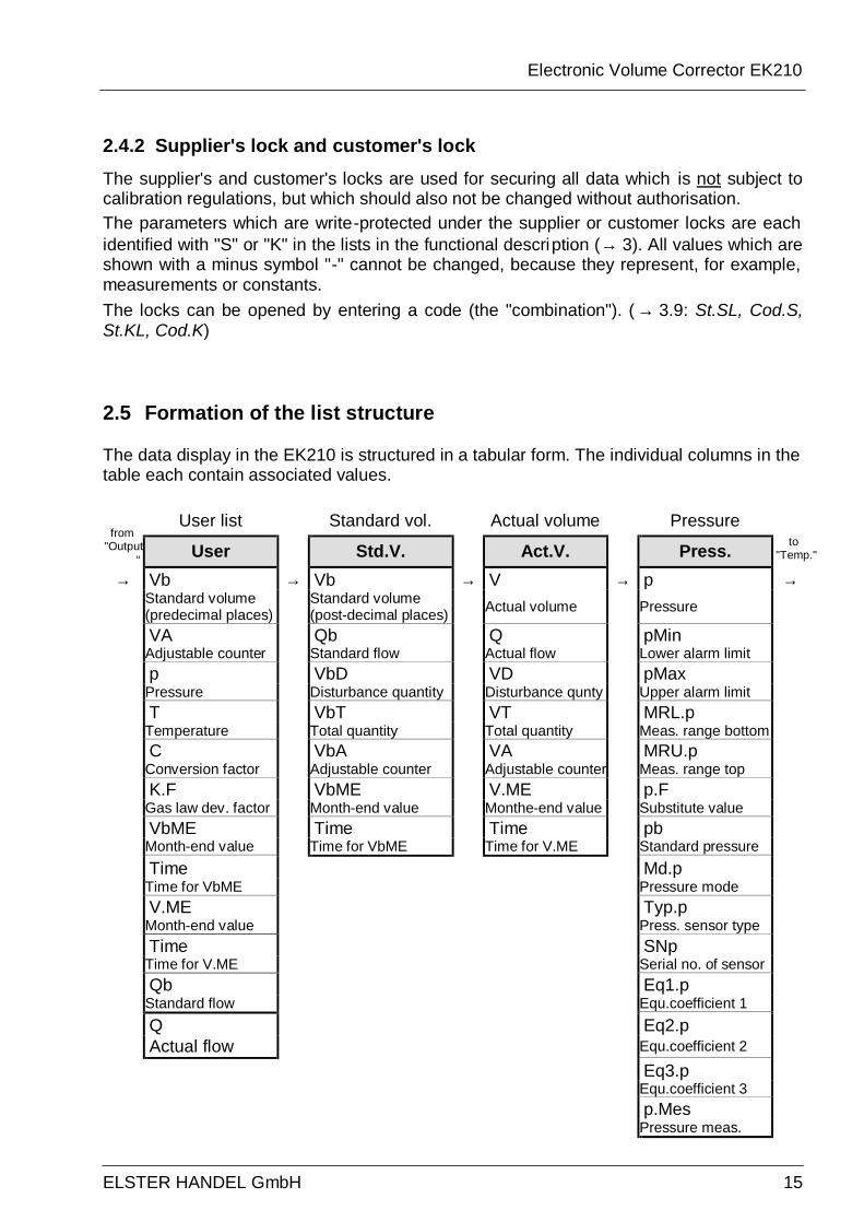
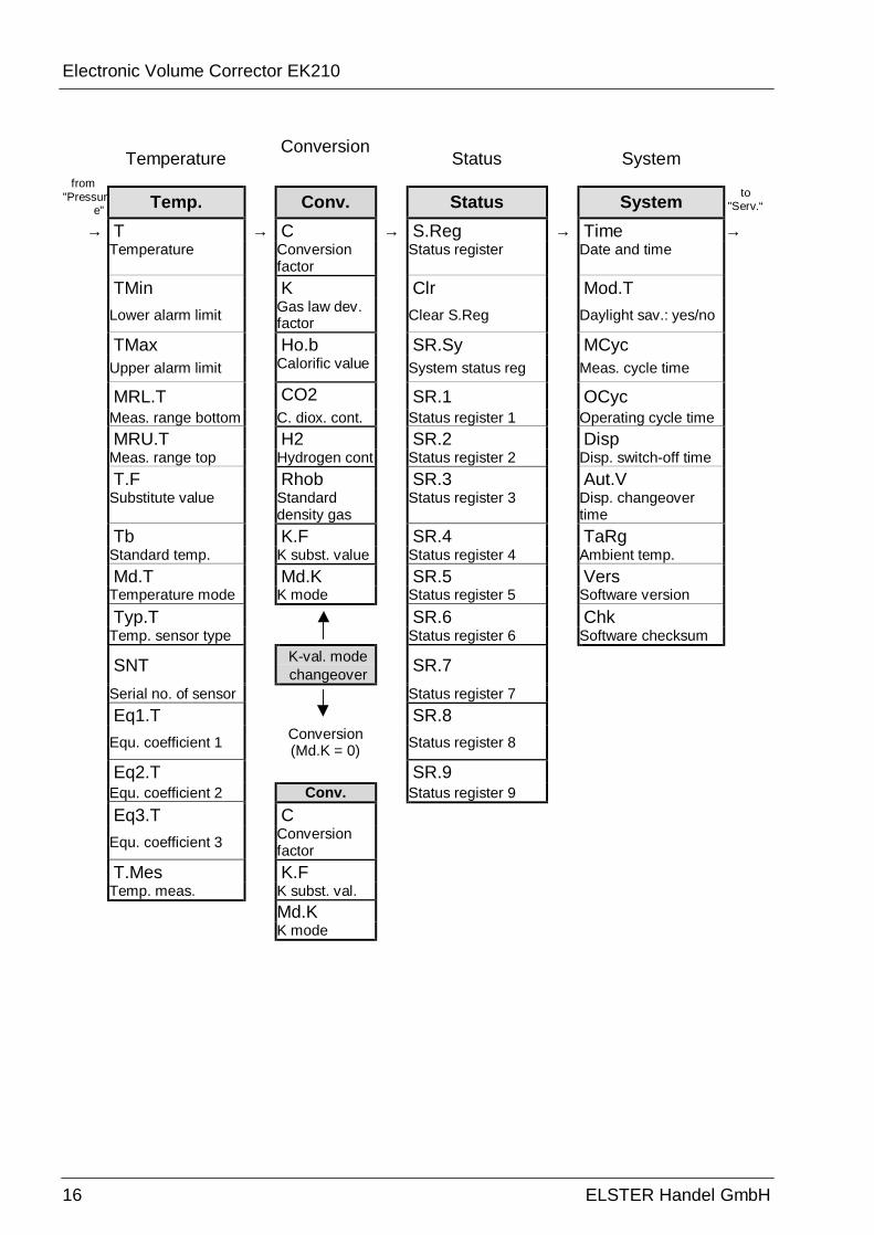
2.5 Formation of the list structure
The data display in the EK210 is structured in a tabular form. The individual columns in the table each contain associated values.
User list Standard vol. Actual volume Pressure from
"Output“ User Std.V. Act.V. Press. to
"Temp."
→ Vb → Vb → V → p → Standard volume
(predecimal places) Standard volume (post-decimal places) Actual volume Pressure
VA Qb Q pMin Adjustable counter Standard flow Actual flow Lower alarm limit p VbD VD pMax
Pressure Disturbance quantity Disturbance qunty Upper alarm limit T VbT VT MRL.p
Temperature Total quantity Total quantity Meas. range bottom C VbA VA MRU.p
Conversion factor Adjustable counter Adjustable counter Meas. range top K.F VbME V.ME p.F
Gas law dev. factor Month-end value Monthe-end value Substitute value VbME Time Time pb
Month-end value Time for VbME Time for V.ME Standard pressure Time Md.p
Time for VbME Pressure mode V.ME Typ.p
Month-end value Press. sensor type Time SNp
Time for V.ME Serial no. of sensor Qb Eq1.p
Standard flow Equ.coefficient 1 Q Eq2.p Actual flow Equ.coefficient 2 Eq3.p
Equ.coefficient 3 p.Mes
Pressure meas.
Electronic Volume Corrector EK210
16 ELSTER Handel GmbH
Temperature Conversion
Status System from
"Pressure" Temp. Conv. Status System to
"Serv.“ → T → C → S.Reg → Time → Temperature Conversion
factor Status register Date and time
TMin K Clr Mod.T Lower alarm limit Gas law dev.
factor Clear S.Reg Daylight sav.: yes/no
TMax Ho.b SR.Sy MCyc Upper alarm limit Calorific value System status reg Meas. cycle time
MRL.T CO2 SR.1 OCyc Meas. range bottom C. diox. cont. Status register 1 Operating cycle time MRU.T H2 SR.2 Disp
Meas. range top Hydrogen cont Status register 2 Disp. switch-off time T.F Rhob SR.3 Aut.V
Substitute value Standard density gas
Status register 3 Disp. changeover time
Tb K.F SR.4 TaRg Standard temp. K subst. value Status register 4 Ambient temp. Md.T Md.K SR.5 Vers
Temperature mode K mode Status register 5 Software version Typ.T SR.6 Chk
Temp. sensor type Status register 6 Software checksum
SNT K-val. mode changeover SR.7
Serial no. of sensor
Status register 7 Eq1.T SR.8
Equ. coefficient 1 Conversion (Md.K = 0) Status register 8
Eq2.T SR.9 Equ. coefficient 2 Conv. Status register 9 Eq3.T C
Equ. coefficient 3 Conversion factor
T.Mes K.F Temp. meas. K subst. val. Md.K K mode
Electronic Volume Corrector EK210
ELSTER HANDEL GmbH 17
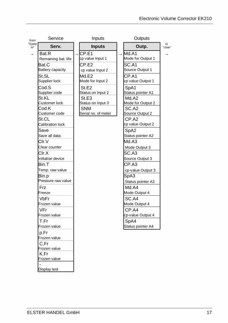
Service Inputs Outputs from "Syste
m“ Serv. Inputs Outp. to "User“
→ Bat.R → CP.E1 → Md.A1 → Remaining bat. life cp value Input 1 Mode for Output 1
Bat.C CP.E2 SC.A1 Battery capacity cp value Input 2 Source Output 1
St.SL Md.E2 CP.A1 Supplier lock Mode for Input 2 cp value Output 1
Cod.S St.E2 SpA1 Supplier code Status on Input 2 Status pointer A1 St.KL St.E3 Md.A2
Customer lock Status on Input 3 Mode for Output 2 Cod.K SNM SC.A2
Customer code Serial no. of meter Source Output 2 St.CL CP.A2
Calibration lock cp value Output 2
Save SpA2 Save all data Status pointer A2 Clr.V Md.A3 Clear counter Mode Output 3
Clr.X SC.A3 Initialise device Source Output 3 Bin.T CP.A3 Temp. raw value cp-value Output 3
Bin.p SpA3 Pressure raw value Status pointer A3
Frz Md.A4 Freeze Mode Output 4 VbFr SC.A4
Frozen value Mode Output 4
VFr CP.A4 Frozen value cp-value Output 4
T.Fr SpA4 Frozen value Status pointer A4 p.Fr
Frozen value C.Fr
Frozen value K.Fr
Frozen value -
Display test
Electronic Volume Corrector EK210
18 ELSTER Handel GmbH
3 Functional description
The data display is structured in tabular form (list structure) (→ 2.5). The individual columns in the table each contain associated values. The following functional description is orientated to this list structure. Here, the following abbreviations are used:
- SD Abbreviated designation Designation of the value in the display
- Access Write access Indicates which lock must be opened to change the value (→ 2.4.1, 2.4.2): - C = Calibration lock - M = Manufacturer's lock - S = Supplier's lock - K = Customer's lock If the letter is located in brackets, the value can only be changed via the interface and not via the keypad.
- Address Address of the value. This is required especially for data transmission via the serial interface.
- DC Data class The data class shows, amongst other properties, whether and how the value can be changed. (→ 2.3.1)
Electronic Volume Corrector EK210
ELSTER HANDEL GmbH 19
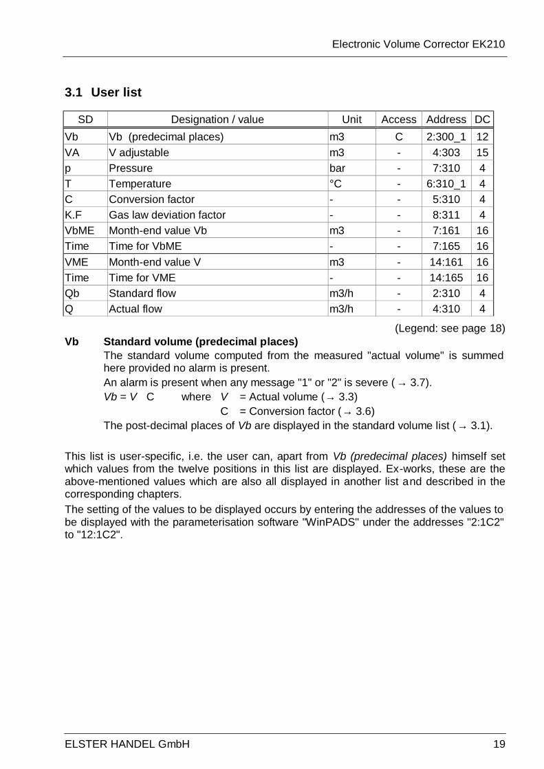
3.1 User list
SD Designation / value Unit Access Address DC Vb Vb (predecimal places) m3 C 2:300_1 12 VA V adjustable m3 - 4:303 15 p Pressure bar - 7:310 4 T Temperature °C - 6:310_1 4 C Conversion factor - - 5:310 4 K.F Gas law deviation factor - - 8:311 4 VbME Month-end value Vb m3 - 7:161 16 Time Time for VbME - - 7:165 16 VME Month-end value V m3 - 14:161 16 Time Time for VME - - 14:165 16 Qb Standard flow m3/h - 2:310 4 Q Actual flow m3/h - 4:310 4
(Legend: see page 18) Vb Standard volume (predecimal places)
The standard volume computed from the measured "actual volume" is summed here provided no alarm is present. An alarm is present when any message "1" or "2" is severe ( → 3.7). Vb = V û C where V = Actual volume (→ 3.3) C = Conversion factor (→ 3.6) The post-decimal places of Vb are displayed in the standard volume list (→ 3.1).
This list is user-specific, i.e. the user can, apart from Vb (predecimal places) himself set which values from the twelve positions in this list are displayed. Ex-works, these are the above-mentioned values which are also all displayed in another list and described in the corresponding chapters. The setting of the values to be displayed occurs by entering the addresses of the values to be displayed with the parameterisation software "WinPADS" under the addresses "2:1C2" to "12:1C2".
Electronic Volume Corrector EK210
20 ELSTER Handel GmbH
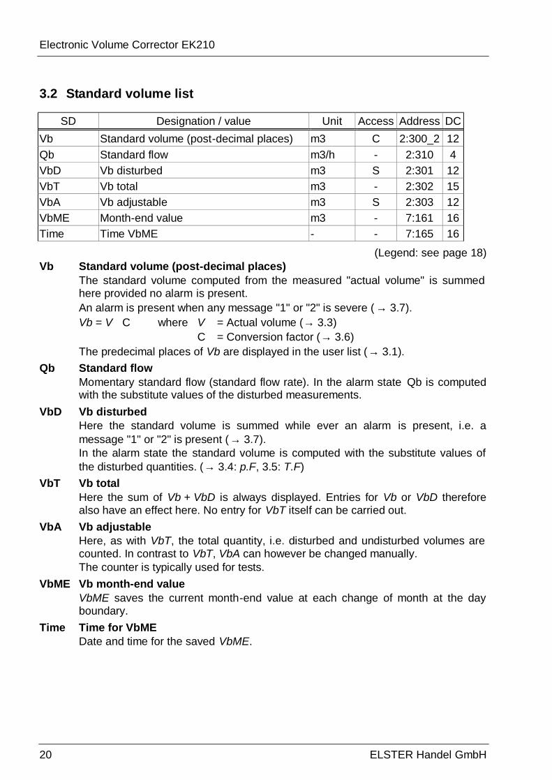
3.2 Standard volume list
SD Designation / value Unit Access Address DC Vb Standard volume (post-decimal places) m3 C 2:300_2 12 Qb Standard flow m3/h - 2:310 4 VbD Vb disturbed m3 S 2:301 12 VbT Vb total m3 - 2:302 15 VbA Vb adjustable m3 S 2:303 12 VbME Month-end value m3 - 7:161 16 Time Time VbME - - 7:165 16
(Legend: see page 18) Vb Standard volume (post-decimal places)
The standard volume computed from the measured "actual volume" is summed here provided no alarm is present. An alarm is present when any message "1" or "2" is severe ( → 3.7). Vb = V û C where V = Actual volume (→ 3.3) C = Conversion factor (→ 3.6) The predecimal places of Vb are displayed in the user list (→ 3.1).
Qb Standard flow Momentary standard flow (standard flow rate). In the alarm state Qb is computed with the substitute values of the disturbed measurements.
VbD Vb disturbed Here the standard volume is summed while ever an alarm is present, i.e. a message "1" or "2" is present (→ 3.7). In the alarm state the standard volume is computed with the substitute values of the disturbed quantities. (→ 3.4: p.F, 3.5: T.F)
VbT Vb total Here the sum of Vb + VbD is always displayed. Entries for Vb or VbD therefore also have an effect here. No entry for VbT itself can be carried out.
VbA Vb adjustable Here, as with VbT, the total quantity, i.e. disturbed and undisturbed volumes are counted. In contrast to VbT, VbA can however be changed manually. The counter is typically used for tests.
VbME Vb month-end value VbME saves the current month-end value at each change of month at the day boundary.
Time Time for VbME Date and time for the saved VbME.

Electronic Volume Corrector EK210
ELSTER HANDEL GmbH 21
3.3 Actual volume list
SD Designation / value Unit Access Address DC V Actual volume m3 C 4:300 12 Q Actual flow m3/h - 4:310 4 VD V disturbed m3 S 4:301 12 VT V total m3 - 4:302 15 VA V adjustable m3 S 4:303 12 V.ME Month-end value m3 - 14:161 16 Time Time for VME - - 14:165 16
(Legend: see page 18) V Actual volume
The volume measured on Input 1 is summed here provided no alarm is present. An alarm is present when any message "1" or "2" is severe ( → 3.7).
Q Actual flow rate Momentary actual flow (actual flow rate).
VD V disturbed Here the actual volume is summed while ever an alarm is present, i.e. a message "1" or "2" is present (→ 3.7).
VT V total Here the sum of V + VD is always displayed. Entries for V or VD therefore also have an effect here. No entry for VT itself can be carried out.
VA V adjustable Here, as with VT, the total quantity, i.e. disturbed and undisturbed volumes are counted. In contrast to VT, VA can however be changed manually. This counter is typically set to the same reading as the gas meter in order to be able to easily detect deviations by comparison of the two counter readings.
V.ME V month-end value V.ME saves the current month-end value at each change of month at the day boundary.
Time Time for V.ME Date and time for the saved VME.
Electronic Volume Corrector EK210
22 ELSTER Handel GmbH
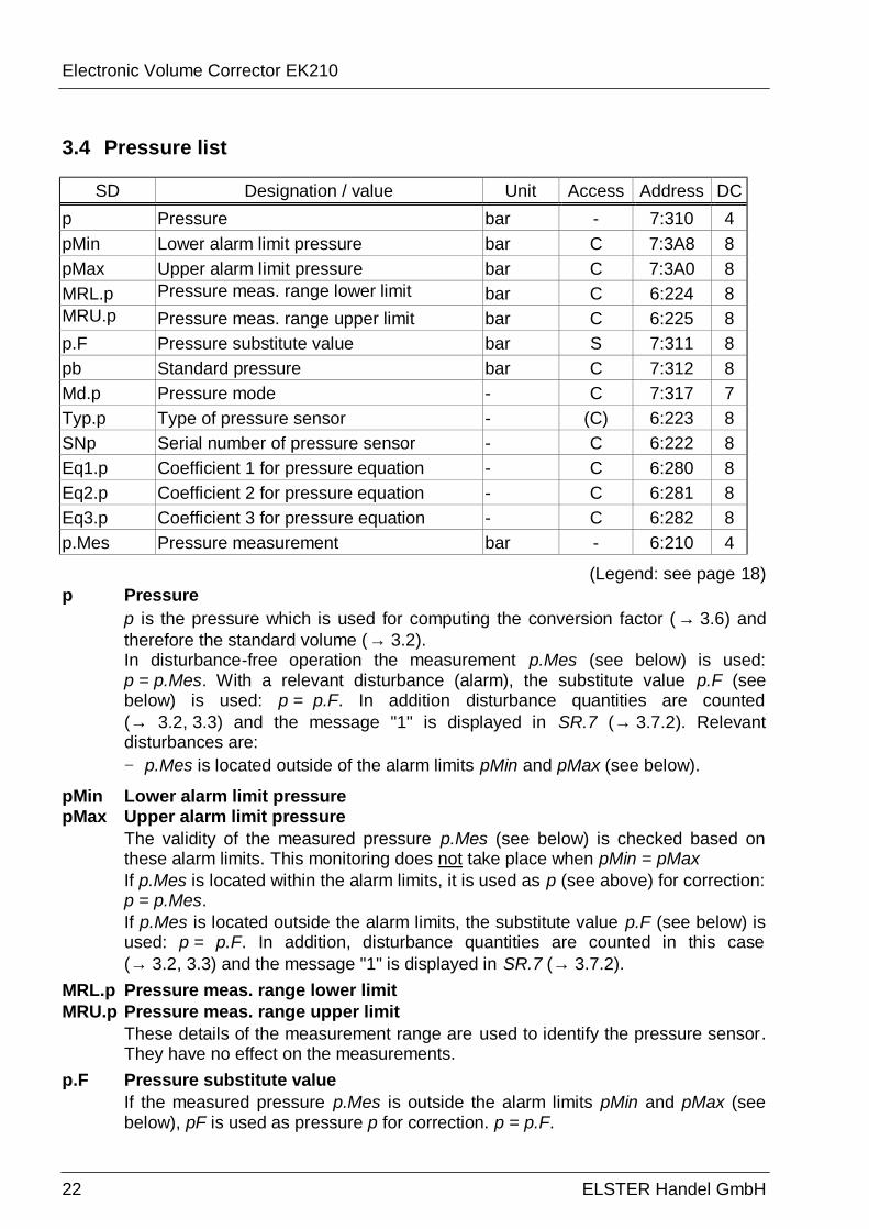
3.4 Pressure list
SD Designation / value Unit Access Address DC p Pressure bar - 7:310 4 pMin Lower alarm limit pressure bar C 7:3A8 8 pMax Upper alarm limit pressure bar C 7:3A0 8 MRL.p Pressure meas. range lower limit bar C 6:224 8 MRU.p Pressure meas. range upper limit bar C 6:225 8 p.F Pressure substitute value bar S 7:311 8 pb Standard pressure bar C 7:312 8 Md.p Pressure mode - C 7:317 7 Typ.p Type of pressure sensor - (C) 6:223 8 SNp Serial number of pressure sensor - C 6:222 8 Eq1.p Coefficient 1 for pressure equation - C 6:280 8 Eq2.p Coefficient 2 for pressure equation - C 6:281 8 Eq3.p Coefficient 3 for pressure equation - C 6:282 8 p.Mes Pressure measurement bar - 6:210 4
(Legend: see page 18) p Pressure
p is the pressure which is used for computing the conversion factor ( → 3.6) and therefore the standard volume (→ 3.2). In disturbance-free operation the measurement p.Mes (see below) is used: p = p.Mes. With a relevant disturbance (alarm), the substitute value p.F (see below) is used: p = p.F. In addition disturbance quantities are counted (→ 3.2, 3.3) and the message "1" is displayed in SR.7 (→ 3.7.2). Relevant disturbances are: − p.Mes is located outside of the alarm limits pMin and pMax (see below).
pMin Lower alarm limit pressure pMax Upper alarm limit pressure
The validity of the measured pressure p.Mes (see below) is checked based on these alarm limits. This monitoring does not take place when pMin = pMax If p.Mes is located within the alarm limits, it is used as p (see above) for correction: p = p.Mes. If p.Mes is located outside the alarm limits, the substitute value p.F (see below) is used: p = p.F. In addition, disturbance quantities are counted in this case (→ 3.2, 3.3) and the message "1" is displayed in SR.7 (→ 3.7.2).
MRL.p Pressure meas. range lower limit MRU.p Pressure meas. range upper limit
These details of the measurement range are used to identify the pressure sensor. They have no effect on the measurements.
p.F Pressure substitute value If the measured pressure p.Mes is outside the alarm limits pMin and pMax (see below), pF is used as pressure p for correction. p = p.F.
Electronic Volume Corrector EK210
ELSTER HANDEL GmbH 23
pb Standard pressure The standard pressure is used for computing the conversion factor ( → 3.6) and hence the standard volume.
Md.p Pressure mode With Md.p = "1" the measured pressure p.Mes (see below) is used for correction, provided it does not violate the alarm limits. With Md.p = "0" the fixed value (substitute value) p.F is always used for correction. No disturbance quantities are counted.
Typ.p Pressure sensor type SNp Serial no. of pressure sensor
Identification of the pressure sensor associated with the EK210.
Eq1.p Coefficient 1 of pressure equation Eq2.p Coefficient 2 of pressure equation Eq3.p Coefficient 3 of pressure equation
The coefficients of the quadratic equation for calculating the pressure p.Mes from the raw pressure value Bin.p (→ 3.9): p.Mes = Eq1.p + Eq2.p û Bin.p + Eq3.p û Bin.p2 To adjust the pressure measurement circuit, the three coefficients of the quadratic equation can either be found by the EK210 itself or calculated and entered by the user and can be set via WinPADS. External to the EK210, the three coefficients can be calculated based on three values for Bin.p and the corresponding reference values. When the EK210 determines the coefficients, it uses the value for Eq3.p available at the time of entering and it calculates the corresponding Eq1.p and Eq2.p for this. Standard for Eq3.p is “0”.
p.Mes Pressure measurement If the measured pressure p.Mes is within the alarm limits pMin and pMax (see above), then it is used as the pressure p for correction: p = p.Mes.
Electronic Volume Corrector EK210
24 ELSTER Handel GmbH
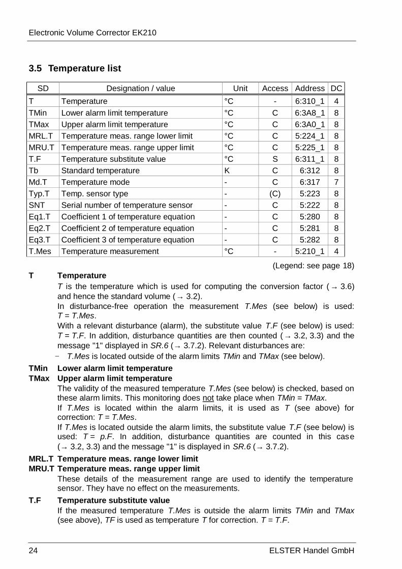
3.5 Temperature list
SD Designation / value Unit Access Address DC T Temperature °C - 6:310_1 4 TMin Lower alarm limit temperature °C C 6:3A8_1 8 TMax Upper alarm limit temperature °C C 6:3A0_1 8 MRL.T Temperature meas. range lower limit °C C 5:224_1 8 MRU.T Temperature meas. range upper limit °C C 5:225_1 8 T.F Temperature substitute value °C S 6:311_1 8 Tb Standard temperature K C 6:312 8 Md.T Temperature mode - C 6:317 7 Typ.T Temp. sensor type - (C) 5:223 8 SNT Serial number of temperature sensor - C 5:222 8 Eq1.T Coefficient 1 of temperature equation - C 5:280 8 Eq2.T Coefficient 2 of temperature equation - C 5:281 8 Eq3.T Coefficient 3 of temperature equation - C 5:282 8 T.Mes Temperature measurement °C - 5:210_1 4
(Legend: see page 18) T Temperature
T is the temperature which is used for computing the conversion factor (→ 3.6) and hence the standard volume (→ 3.2). In disturbance-free operation the measurement T.Mes (see below) is used: T = T.Mes. With a relevant disturbance (alarm), the substitute value T.F (see below) is used: T = T.F. In addition, disturbance quantities are then counted (→ 3.2, 3.3) and the message "1" displayed in SR.6 (→ 3.7.2). Relevant disturbances are:
− T.Mes is located outside of the alarm limits TMin and TMax (see below).
TMin Lower alarm limit temperature TMax Upper alarm limit temperature
The validity of the measured temperature T.Mes (see below) is checked, based on these alarm limits. This monitoring does not take place when TMin = TMax. If T.Mes is located within the alarm limits, it is used as T (see above) for correction: T = T.Mes. If T.Mes is located outside the alarm limits, the substitute value T.F (see below) is used: T = p.F. In addition, disturbance quantities are counted in this case (→ 3.2, 3.3) and the message "1" is displayed in SR.6 (→ 3.7.2).
MRL.T Temperature meas. range lower limit MRU.T Temperature meas. range upper limit
These details of the measurement range are used to identify the temperature sensor. They have no effect on the measurements.
T.F Temperature substitute value If the measured temperature T.Mes is outside the alarm limits TMin and TMax (see above), TF is used as temperature T for correction. T = T.F.
Electronic Volume Corrector EK210
ELSTER HANDEL GmbH 25
Tn Standard temperature The standard temperature is used for computing the conversion factor ( → 3.6) and hence the standard volume.
Md.T Temperature mode With Md.T = "1" the measured temperature T.Mes (see below) is used for correction, provided it does not violate the alarm limits . With Md.T = "0" the fixed value (substitute value) T.F is always used for correction. No disturbance quantities are counted.
Typ.T Temperature sensor type SNT Serial number of temperature sensor
Identification of the temperature sensor associated with the E K210.
Eq1.T Coefficient 1 of temperature equation Eq2.T Coefficient 2 of temperature equation Eq3.T Coefficient 3 of temperature equation
The coefficients of the quadratic equation for calculating the temperature T.Mes from the raw temperature value Bin.T (→ 3.9): T.Mes = Eq1.T + Eq2.T û Bin.T + Eq3.T û Bin.T2 To adjust the pressure measurement circuit, the three coefficients of the quadratic equation can either be found by the EK210 itself or calculated and entered by the user. External to the EK210, the three coefficients can be calculated based on three values for Bin.T and the corresponding reference values. When the EK210 determines the coefficients, it uses the value for Eq3.T set at the time of entry and it calculates the corresponding Eq1.T and Eq2.T for this. The standard value for Eq3.T is 2.6975û10-7.
T.Mes Temperature measurement If the measured temperature T.Mes is within the alarm limits TMin and TMax (see above), then it is used as the temperature T (see above) for correction. T = T.Mes.
Electronic Volume Corrector EK210
26 ELSTER Handel GmbH
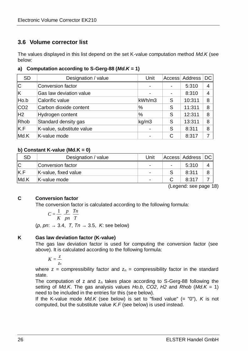
3.6 Volume corrector list
The values displayed in this list depend on the set K-value computation method Md.K (see below:
a) Computation according to S-Gerg-88 (Md.K = 1)
SD Designation / value Unit Access Address DC C Conversion factor - - 5:310 4 K Gas law deviation value - - 8:310 4 Ho.b Calorific value kWh/m3 S 10:311 8 CO2 Carbon dioxide content % S 11:311 8 H2 Hydrogen content % S 12:311 8 Rhob Standard density gas kg/m3 S 13:311 8 K.F K-value, substitute value - S 8:311 8 Md.K K-value mode - C 8:317 7 b) Constant K-value (Md.K = 0)
SD Designation / value Unit Access Address DC C Conversion factor - - 5:310 4 K.F K-value, fixed value - S 8:311 8 Md.K K-value mode - C 8:317 7
(Legend: see page 18) C Conversion factor
The conversion factor is calculated according to the following formula:
TTn
pnp
KC ⋅⋅=
1
(p, pn: → 3.4, T, Tn → 3.5, K: see below)
K Gas law deviation factor (K-value) The gas law deviation factor is used for computing the conversion factor (see above). It is calculated according to the following formula:
nzzK =
where z = compressibility factor and zn = compressibility factor in the standard state. The computation of z and zn takes place according to S-Gerg-88 following the setting of Md.K. The gas analysis values Ho.b, CO2, H2 and Rhob (Md.K = 1) need to be included in the entries for this (see below). If the K-value mode Md.K (see below) is set to "fixed value" (= "0"), K is not computed, but the substitute value K.F (see below) is used instead.
Electronic Volume Corrector EK210
ELSTER HANDEL GmbH 27
Ho.b Calorific value CO2 Carbon dioxide content H2 Hydrogen content Rhob Standard density gas
These gas analysis values must be entered so that the gas law deviation value K can be correctly computed. Range of validity: Ho.b 6,0 ... 13,0 kWh/m3
CO2 0,0 ... 30,0 Mol-% H2 0,0 ... 10,0 Mol-% Rhob 0,71 ... 1,16 kg/m3
F For Ho.b and Rhob the values converted to the German standard must be entered.
F Furthermore, the following limits must be ensured by the gas supplier: Methane CH4 50 - 100 % Propane C3H8 0 - 5 % Nitrogen N2 0 - 50 % Butane C4H10 0 - 1 % Ethane C2H6 0 - 20 % Pentane C5H12 0 – 0.5 %
K.F K-value, substitute value If the K-value mode Md.K (see below) is set to "fixed value" (= "0"), the constant substitute value K.F is used instead of the calculated gas law deviation value K for the computation of the conversion factor C (see above).
Md.K K-value mode
With Md.K you can set whether the conversion factor C (→ 3.6) and hence the standard volume Vb (→ 3.2) are determined with the calculated K-value or with the constant K-value, K.F: Md.K = "0": The fixed value (substitute value) K.F is used. Md.K = "1": The K-value is calculated according to S-Gerg-88.
Electronic Volume Corrector EK210
28 ELSTER Handel GmbH
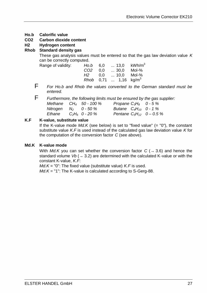
3.7 Status list
SD Designation / value Unit Access Address DC S.Reg Status register, total - - 1:101 19 Clr Clear status register - S 4:130 2 SR.Sy System status register - - 2:101 19 SR.1 Status register 1 - - 1:111 19 SR.2 Status register 2 - - 2:111 19 SR.3 Status register 3 - - 3:111 19 SR.4 Status register 4 - - 4:111 19 SR.5 Status register 5 - - 5:111 19 SR.6 Status register 6 - - 6:111 19 SR.7 Status register 7 - - 7:111 19 SR.8 Status register 8 - - 8:111 19 SR.9 Status register 9 9:111 19
(Legends: see page 18) S.Reg Status register, total
In the status register messages since the last manual clear are collected. Here, it can therefore be seen what, for example, has occurred since the last station inspection. The messages can be cleared in this list with the command "Clr".
The momentary status (1:100) can only be read out by means of WinPADS. Messages in the momentary status indicate current statuses, such as, for example, prevailing errors. When the status is no longer present, the corresponding message is removed from the momentary status. Manual deletion is not possible.
S.Reg combines the messages of all status registers. Message "8" in S.Reg signifies, for example, that message "8" has been entered in at least one of the status registers.
The meaning of the messages displayed is described in the Chapters 3.7.1 and 3.7.2.
Clr Clear status register Here, the content of all status registers, i.e. "S.Reg" and all subordinate status registers (SR.Sy and SR.1 to SR.9), can be cleared. If the alarm or warning states are however still present, they are again directly entered as messages.
SR.Sy System status Display of the system status messages → 3.7.1
SR.1, SR.2, SR.3, SR,4, SR.5, SR.6, SR.7, SR.8, SR.9 Possible messages → 3.7.2
Electronic Volume Corrector EK210
ELSTER HANDEL GmbH 29
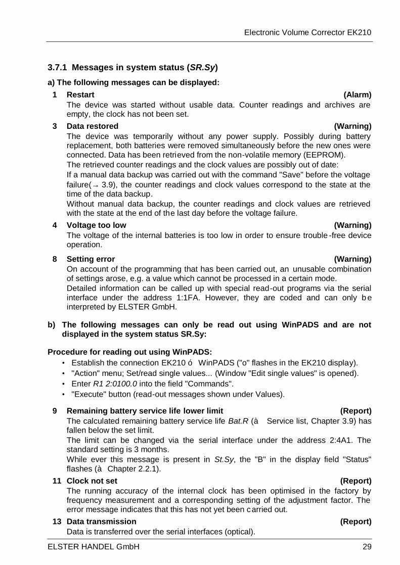
3.7.1 Messages in system status (SR.Sy) a) The following messages can be displayed:
1 Restart (Alarm) The device was started without usable data. Counter readings and archives are empty, the clock has not been set.
3 Data restored (Warning) The device was temporarily without any power supply. Possibly during battery replacement, both batteries were removed simultaneously before the new ones were connected. Data has been retrieved from the non-volatile memory (EEPROM). The retrieved counter readings and the clock values are possibly out of date: If a manual data backup was carried out with the command "Save" before the voltage failure(→ 3.9), the counter readings and clock values correspond to the state at the time of the data backup. Without manual data backup, the counter readings and clock values are retrieved with the state at the end of the last day before the voltage failure.
4 Voltage too low (Warning) The voltage of the internal batteries is too low in order to ensure trouble -free device operation.
8 Setting error (Warning) On account of the programming that has been carried out, an unusable combination of settings arose, e.g. a value which cannot be processed in a certain mode. Detailed information can be called up with special read-out programs via the serial interface under the address 1:1FA. However, they are coded and can only b e interpreted by ELSTER GmbH.
b) The following messages can only be read out using WinPADS and are not displayed in the system status SR.Sy:
Procedure for reading out using WinPADS: • Establish the connection EK210 ó WinPADS ("o" flashes in the EK210 display). • "Action" menu; Set/read single values... (Window "Edit single values" is opened). • Enter R1 2:0100.0 into the field "Commands". • "Execute" button (read-out messages shown under Values).
9 Remaining battery service life lower limit (Report) The calculated remaining battery service life Bat.R (à Service list, Chapter 3.9) has fallen below the set limit. The limit can be changed via the serial interface under the address 2:4A1. The standard setting is 3 months. While ever this message is present in St.Sy, the "B" in the display field "Status" flashes (à Chapter 2.2.1).
11 Clock not set (Report) The running accuracy of the internal clock has been optimised in the factory by frequency measurement and a corresponding setting of the adjustment factor. The error message indicates that this has not yet been carried out.
13 Data transmission (Report) Data is transferred over the serial interfaces (optical).
Electronic Volume Corrector EK210
30 ELSTER Handel GmbH
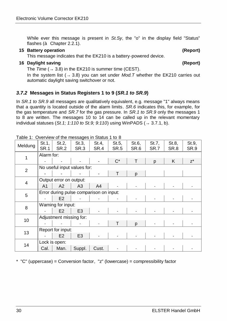
While ever this message is present in St.Sy, the "o" in the display field "Status" flashes (à Chapter 2.2.1).
15 Battery operation (Report) This message indicates that the EK210 is a battery-powered device.
16 Daylight saving (Report) The Time (→ 3.8) in the EK210 is summer time (CEST). In the system list (→ 3.8) you can set under Mod.T whether the EK210 carries out automatic daylight saving switchover or not.
3.7.2 Messages in Status Registers 1 to 9 (SR.1 to SR.9) In SR.1 to SR.9 all messages are qualitatively equivalent, e.g. message "1" always means that a quantity is located outside of the alarm limits. SR.6 indicates this, for example, for the gas temperature and SR.7 for the gas pressure. In SR.1 to SR.9 only the messages 1 to 8 are written. The messages 10 to 14 can be called up in the relevant momentary individual statuses (St.1; 1:110 to St.9; 9:110) using WinPADS (→ 3.7.1, b).
Table 1: Overview of the messages in Status 1 to 8
Meldung St.1, SR.1
St.2, SR.2
St.3, SR.3
St.4, SR.4
St.5, SR.5
St.6, SR.6
St.7, SR.7
St.8, SR.8
St.9, SR.9
Alarm for: 1 - - - - C* T p K z*
No useful input values for: 2 - - - - T p
Output error on output: 4 A1 A2 A3 A4 - - - - -
Error during pulse comparison on input: 5 - E2 - - - - - - -
Warning for input: 8 - E2 E3 - - - - - -
Adjustment missing for: 10 - - - - T p - - -
Report for input: 13 - E2 E3 - - - - - -
Lock is open: 14 Cal. Man. Suppl. Cust. - - - - -
* "C" (uppercase) = Conversion factor, "z" (lowercase) = compressibility factor

Electronic Volume Corrector EK210
ELSTER HANDEL GmbH 31
SR.1 Status Register 1 a) The following messages can be displayed:
4 Error on Output 1 (Warning) The volume pulses to be passed through an output are temporarily saved in a pulse buffer. The buffer can accommodate 65535 pulses. If the volume to be output is continuously greater than that which can be output in the form of pulses, the pulse buffer continually fills and will eventually reach its maximum state. If then further pulses arrive, these can no longer be temporarily saved and are lost. The pulse buffer remains at its maximum state in this case. Message "4" indicates that pulses have been lost in this way. If the pulse buffer drops below the level of 65000 pulses, the message is cleared again. To rectify the cause of this problem, the cp value of the output (→ 3.11 Output list) can be reduced or the output frequency (address 1:617) increased with an AS-200 Read-out Device or the WinPADS Parameterisation Software. With a change of the output cp value, the corresponding input buffer is cleared .
b) The following messages can only be read out using WinPADS and are not
displayed in SR.1:
14 Calibration lock open (Report) For protection against unauthorised parameterisation or reading out via a serial interface, the EK210 has a total of four locks in the following order of priority: Calibration, manufacturer's, supplier's and customer's locks. The calibration lock can be opened and closed using a sealable pushbutton which is located inside the device (→ 5.4.1). Closure is also possible by deleting the value "St.PL" (→ 3.9) via the keypad or interface.
While ever this message can be read out in St.1 (1:110), the "P" in the display field "Status" flashes (→ Chapter 2.2.1).
SR.2 Status Register 2 a) The following messages can be displayed:
4 Error on Output 2 (Warning) The pulse buffer for Output 2 has overflowed (for further explanation: See message 4 for SR.1).
5 Error during pulse comparison on Input 2 (Warning) Input 2 (E2) can be parameterised for monitoring as a pulse or signal input. When used as a pulse input, the pulses arriving on E2 can, for example, be compared with those on Input 1. If the deviation is too great, message "5" is displayed in SR.3. Settings for comparing pulses can be loaded into the EK210 via parameter files using WinPADS. Further explanation for this: → 3.10.
Electronic Volume Corrector EK210
32 ELSTER Handel GmbH
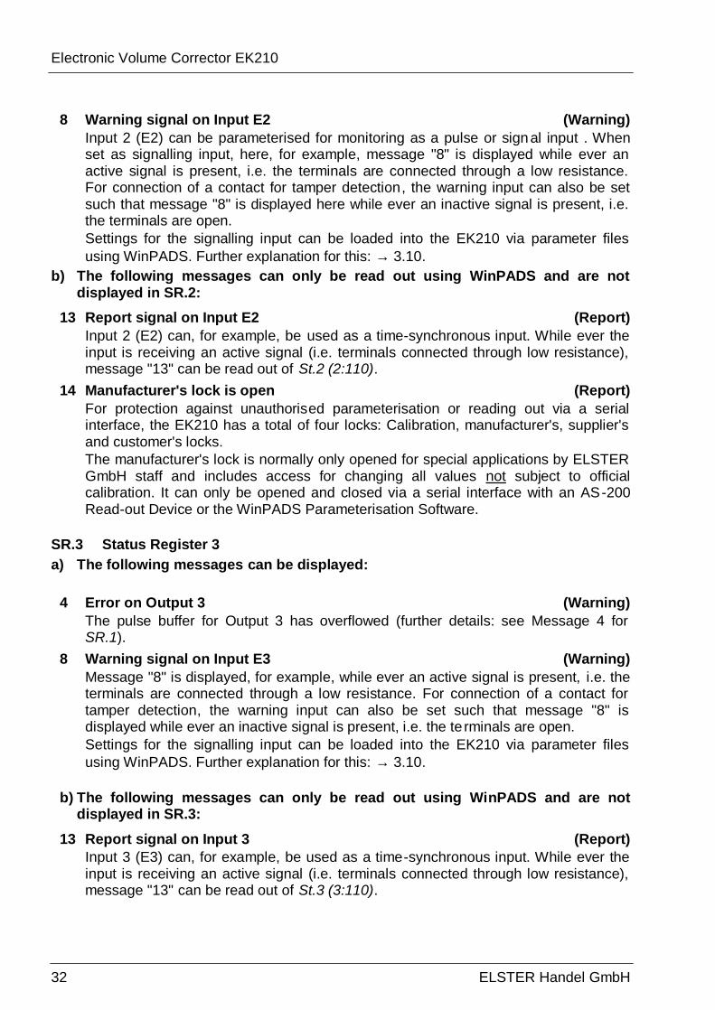
8 Warning signal on Input E2 (Warning) Input 2 (E2) can be parameterised for monitoring as a pulse or signal input . When set as signalling input, here, for example, message "8" is displayed while ever an active signal is present, i.e. the terminals are connected through a low resistance. For connection of a contact for tamper detection, the warning input can also be set such that message "8" is displayed here while ever an inactive signal is present, i.e. the terminals are open. Settings for the signalling input can be loaded into the EK210 via parameter files using WinPADS. Further explanation for this: → 3.10.
b) The following messages can only be read out using WinPADS and are not displayed in SR.2:
13 Report signal on Input E2 (Report) Input 2 (E2) can, for example, be used as a time-synchronous input. While ever the input is receiving an active signal (i.e. terminals connected through low resistance), message "13" can be read out of St.2 (2:110).
14 Manufacturer's lock is open (Report) For protection against unauthorised parameterisation or reading out via a serial interface, the EK210 has a total of four locks: Calibration, manufacturer's, supplier's and customer's locks. The manufacturer's lock is normally only opened for special applications by ELSTER GmbH staff and includes access for changing all values not subject to official calibration. It can only be opened and closed via a serial interface with an AS-200 Read-out Device or the WinPADS Parameterisation Software.
SR.3 Status Register 3 a) The following messages can be displayed:
4 Error on Output 3 (Warning) The pulse buffer for Output 3 has overflowed (further details: see Message 4 for SR.1).
8 Warning signal on Input E3 (Warning) Message "8" is displayed, for example, while ever an active signal is present, i.e. the terminals are connected through a low resistance. For connection of a contact for tamper detection, the warning input can also be set such that message "8" is displayed while ever an inactive signal is present, i.e. the te rminals are open. Settings for the signalling input can be loaded into the EK210 via parameter files using WinPADS. Further explanation for this: → 3.10.
b) The following messages can only be read out using WinPADS and are not displayed in SR.3:
13 Report signal on Input 3 (Report) Input 3 (E3) can, for example, be used as a time-synchronous input. While ever the input is receiving an active signal (i.e. terminals connected through low resistance), message "13" can be read out of St.3 (3:110).

Electronic Volume Corrector EK210
ELSTER HANDEL GmbH 33
14 Supplier's lock is open (Report) For protection against unauthorised parameterisation or reading out via a serial interface, the EK210 has a total of four locks: Calibration, manufacturer's, supplier's and customer's locks. The supplier's lock is normally used by the gas supplier. It permits changing various values which are not subject to calibration regulations. The relevant values are identified with an "S" in the lists (→ 3 EK210 Electronic State Volume Corrector). The supplier's lock can be opened and closed with "Cod.S" and "St.SL" (→ 3.9).
SR.4 Status Register 4 a) The following messages can be displayed:
4 Error on Output 4 (Warning) The pulse buffer for Output 4 has overflowed (further details: see Message 4 for SR.1).
b) The following messages can only be read out using WinPADS and are not displayed in SR.4:
14 Customer's lock is open (Report) For protection against unauthorised parameterisation or reading out via a serial interface, the EK210 has a total of four locks: Calibration, manufacturer's, supplier's and customer's locks. The customer's lock is normally used by gas customers. It permits changing various values which are not subject to calibration regulations. The relevant values are identified with a "K" in the lists (→ 3). The customer's lock can be opened and closed with "Cod.K" and "St.SL" (→ 3.9).
SR.5 Status Register 5 a) The following messages can be displayed:
1 Conversion factor cannot be computed (Alarm) The conversion factor C (→ 3.6) cannot be computed because the temperature T (→ 3.5) is outside the range -100°C to +100°C or no usable gas law deviation value K (→ 3.6) is available. Possibly the temperature sensor is not connected correctly or the substitute value for the gas law deviation value K.F (→ 3.6) has the value "0". The conversion factor is set to "0" and disturbance quantities for V are counted in VD (→ 3.3). With the correct device setting, this message does not occur, because, for example, when an alarm limit, TMin or TMax (→ 3.5), is exceeded, the temperature substitute value T.F is used.
Electronic Volume Corrector EK210
34 ELSTER Handel GmbH
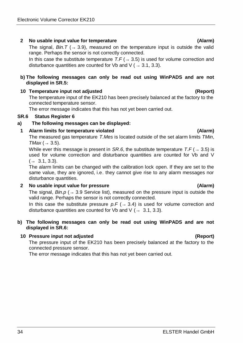
2 No usable input value for temperature (Alarm) The signal, Bin.T (→ 3.9), measured on the temperature input is outside the valid range. Perhaps the sensor is not correctly connected. In this case the substitute temperature T.F (→ 3.5) is used for volume correction and disturbance quantities are counted for Vb and V (→ 3.1, 3.3).
b) The following messages can only be read out using WinPADS and are not displayed in SR.5:
10 Temperature input not adjusted (Report) The temperature input of the EK210 has been precisely balanced at the factory to the connected temperature sensor. The error message indicates that this has not yet been carried out.
SR.6 Status Register 6 a) The following messages can be displayed:
1 Alarm limits for temperature violated (Alarm) The measured gas temperature T.Mes is located outside of the set alarm limits TMin, TMax (→ 3.5). While ever this message is present in SR.6, the substitute temperature T.F (→ 3.5) is used for volume correction and disturbance quantities are counted for Vb and V (→ 3.1, 3.3). The alarm limits can be changed with the calibration lock open. If they are set to the same value, they are ignored, i.e. they cannot give rise to any alarm messages nor disturbance quantities.
2 No usable input value for pressure (Alarm) The signal, Bin.p (→ 3.9 Service list), measured on the pressure input is outside the valid range. Perhaps the sensor is not correctly connected. In this case the substitute pressure p.F (→ 3.4) is used for volume correction and disturbance quantities are counted for Vb and V (→ 3.1, 3.3).
b) The following messages can only be read out using WinPADS and are not displayed in SR.6:
10 Pressure input not adjusted (Report) The pressure input of the EK210 has been precisely balanced at the factory to the connected pressure sensor. The error message indicates that this has not yet been carried out.

Electronic Volume Corrector EK210
ELSTER HANDEL GmbH 35
SR.7 Status Register 7 a) The following messages can be displayed:
1 Alarm limits for pressure violated (Alarm) The measured gas pressure p.Mes is located outside of the set alarm limits pMin, pMax (→ 3.4). While ever this message is present in SR.7, the substitute pressure p.F (→ 3.4) is used for volume correction and disturbance quantities are counted for Vb and V (→ 3.1, 3.3). The alarm limits can be changed with the calibration lock open. If they are set to the same value, they are ignored, i.e. they cannot give rise to any alarm messages nor disturbance quantities.
b) The following messages can only be read out using WinPADS and are not displayed in SR.7:
For the EK210 no further messages are currently applicable here.
SR.8 Status Register 8 a) The following messages can be displayed:
1 Gas law deviation factor cannot be computed (Alarm) The gas law deviation value K (→ 3.6) cannot be computed because no valid imperfect-gas factor could be determined. (cf. message "1" in St.9). While ever this problem exists, the substitute value K.F is used for the gas law deviation value and disturbance quantities are counted for Vb and V (→ 3.1, 3.3).
b) The following messages can only be read out using WinPADS and are not displayed in the system status SR.8:
There are currently no further messages applicable here for the EK210. SR.9 Status Register 9 a) The following messages can be displayed:
1 Imperfect-gas factor cannot be computed (Alarm) At least one of the gas analysis values Ho.b, CO2, H2, Rhob (→ 3.6) is located outside of the permissible range. While ever this problem exists, the last valid value for each of the affected gas analysis values is used and disturbance quantities are counted for Vb and V (→ 3.1, 3.3). If a valid value has not yet been able to be calculated (because the gas analysis has not till now been correct), the imperfect-gas factor is set to "0". Consequently therefore, also no gas law deviation value can be computed. (See above: message "1" in St.8).
b) The following messages can only be read out using WinPADS and are not displayed in the system status SR.9:
There are currently no further messages applicable here for the EK210.
Electronic Volume Corrector EK210
36 ELSTER Handel GmbH
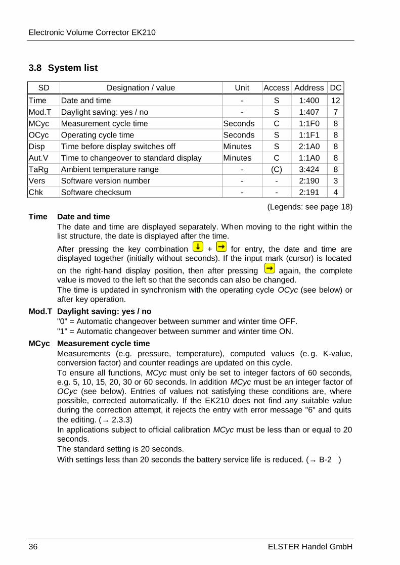
3.8 System list
SD Designation / value Unit Access Address DC Time Date and time - S 1:400 12 Mod.T Daylight saving: yes / no - S 1:407 7 MCyc Measurement cycle time Seconds C 1:1F0 8 OCyc Operating cycle time Seconds S 1:1F1 8 Disp Time before display switches off Minutes S 2:1A0 8 Aut.V Time to changeover to standard display Minutes C 1:1A0 8 TaRg Ambient temperature range - (C) 3:424 8 Vers Software version number - - 2:190 3 Chk Software checksum - - 2:191 4
(Legends: see page 18) Time Date and time
The date and time are displayed separately. When moving to the right within the list structure, the date is displayed after the time. After pressing the key combination + for entry, the date and time are displayed together (initially without seconds). If the input mark (cursor) is located on the right-hand display position, then after pressing again, the complete value is moved to the left so that the seconds can also be changed. The time is updated in synchronism with the operating cycle OCyc (see below) or after key operation.
Mod.T Daylight saving: yes / no "0" = Automatic changeover between summer and winter time OFF. "1" = Automatic changeover between summer and winter time ON.
MCyc Measurement cycle time Measurements (e.g. pressure, temperature), computed values (e. g. K-value, conversion factor) and counter readings are updated on this cycle. To ensure all functions, MCyc must only be set to integer factors of 60 seconds, e.g. 5, 10, 15, 20, 30 or 60 seconds. In addition MCyc must be an integer factor of OCyc (see below). Entries of values not satisfying these conditions are, where possible, corrected automatically. If the EK210 does not find any suitable value during the correction attempt, it rejects the entry with error message "6" and quits the editing. (→ 2.3.3) In applications subject to official calibration MCyc must be less than or equal to 20 seconds. The standard setting is 20 seconds. With settings less than 20 seconds the battery service life is reduced. (→ B-2 )
Electronic Volume Corrector EK210
ELSTER HANDEL GmbH 37
OCyc Operating cycle time The time and all values which relate to a time interval (e.g. 1 month) are updated on this cycle. OCyc must only be set to values which are integer factors or multiples of 60 seconds and which are also integer multiples of MCyc (see above). Entries of other values are, where possible, corrected automatically. If the EK210 does not find any suitable value during the correction attempt, it rejects the entry with e rror message "6" and quits the editing. (→ 2.3.3) The standard setting is 300 seconds (= 5 minutes). With settings less than 300 seconds the battery service life is reduced. (→ B-2 )
Disp Time before display switches off In order to conserve the batteries the display switches off after key operation once the set time has expired. The setting "0" signifies that the display is always switched on. With settings of "0" or greater than 10 minutes, the battery service life is reduced.
TaRg Ambient temperature range The permissible ambient temperature for the EK210 in operation subject to calibration regulations. It mainly depends on the pressure sensor used (→ B-6 Pressure sensor).
Aut.V Time to changeover to standard display After key operation the display automatically changes over to the standard display Vb (→ 3.1) once the time set here has expired. The setting "0" signifies that the display is not switched over. In applications subject to official calibration this setting is not however permissible. The standard setting is 1 minute.
Vers Software version number Chk Software checksum
Version number and checksum provide clear identification of the software implemented in the EK210.
Electronic Volume Corrector EK210
38 ELSTER Handel GmbH
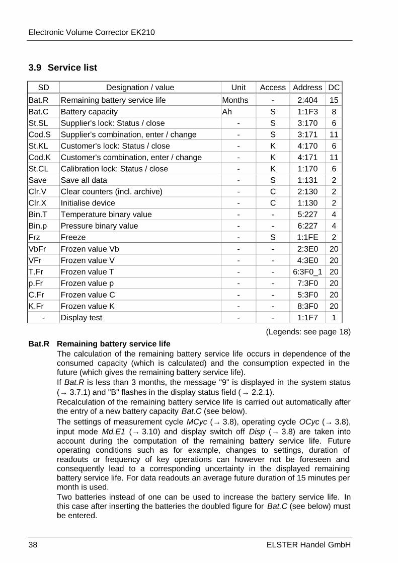
3.9 Service list
SD Designation / value Unit Access Address DC Bat.R Remaining battery service life Months - 2:404 15 Bat.C Battery capacity Ah S 1:1F3 8 St.SL Supplier's lock: Status / close - S 3:170 6 Cod.S Supplier's combination, enter / change - S 3:171 11 St.KL Customer's lock: Status / close - K 4:170 6 Cod.K Customer's combination, enter / change - K 4:171 11 St.CL Calibration lock: Status / close - K 1:170 6 Save Save all data - S 1:131 2 Clr.V Clear counters (incl. archive) - C 2:130 2 Clr.X Initialise device - C 1:130 2 Bin.T Temperature binary value - - 5:227 4 Bin.p Pressure binary value - - 6:227 4 Frz Freeze - S 1:1FE 2 VbFr Frozen value Vb - - 2:3E0 20 VFr Frozen value V - - 4:3E0 20 T.Fr Frozen value T - - 6:3F0_1 20 p.Fr Frozen value p - - 7:3F0 20 C.Fr Frozen value C - - 5:3F0 20 K.Fr Frozen value K - - 8:3F0 20
- Display test - - 1:1F7 1
(Legends: see page 18)
Bat.R Remaining battery service life The calculation of the remaining battery service life occurs in dependence of the consumed capacity (which is calculated) and the consumption expected in the future (which gives the remaining battery service life). If Bat.R is less than 3 months, the message "9" is displayed in the system status (→ 3.7.1) and "B" flashes in the display status field (→ 2.2.1). Recalculation of the remaining battery service life is carried out automatically after the entry of a new battery capacity Bat.C (see below). The settings of measurement cycle MCyc (→ 3.8), operating cycle OCyc (→ 3.8), input mode Md.E1 (→ 3.10) and display switch off Disp (→ 3.8) are taken into account during the computation of the remaining battery service life. Future operating conditions such as for example, changes to settings, duration of readouts or frequency of key operations can however not be foreseen and consequently lead to a corresponding uncertainty in the displayed remaining battery service life. For data readouts an average future duration of 15 minutes per month is used. Two batteries instead of one can be used to increase the battery service life. In this case after inserting the batteries the doubled figure for Bat.C (see below) must be entered.

Electronic Volume Corrector EK210
ELSTER HANDEL GmbH 39
Bat.C Battery capacity Here, the original capacity and not the residual capacity of the batteries last used is displayed. After a battery replacement the capacity of the battery used must be entered here so that recalculation of the remaining battery service life is initiated. The capacity to be entered need not necessarily correspond to the typical capacity quoted by the battery manufacturer. Apart from these details, the capacity depends on the application conditions such as ambient temperature and the device current consumption. In view of this and as a precaution, the minimum and not the typical value should be used. When used in ambient temperatures between –10°C and +50°C, the value to be entered is normally about 80% of the capacity quoted by the manufacturer. With the use of the battery obtainable from Elster of size "D", the value 13 Ah should be entered for Bat.C and 26.0 Ah when 2 cells are used.
St.SL Supplier's lock (status / close) Cod.S Supplier's combination (enter / change) St.KL Customer's lock (status / close) Cod.K Customer's combination (enter / change)
Basic principle of operation of lock and combination: → 2.4.2. Open lock: Enter the correct combination (numerical code) Close lock: Clear St.SL resp. St.KL. Clearing using the keypad
1.) + 2.) (⇒ "0") 3.) + Change combination: Entry of a new combination (code) with lock open.
(irrespective of the above mentioned access rights) The individual characters of the combination code in hexadecimal notation, i.e. they take on values from 0 to 9 and from A to F. "A" follows "9" and "0" follows "F" again.
St.CL Calibration lock (status / close) Basic principle of operation of the calibration lock: → 2.4.1. Opening the calibration lock: Only with the sealed pushbutton (→ 5.4.1). Closing the calibration lock: Either by pressing the button again or by clearing St.CL via interface or keypad. Clearing via keypad: 1.) + 2.) (⇒ „0“) 3.) +
Save Save all data This function should be executed before any battery replacement in order to save the counter readings, date and time in the non-volatile memory (EEPROM).
Clr.V Clear counters (incl. archive) All the counter readings and archives are cleared.
Clr.X Initialise device All data (counter readings, archives and settings) are cleared.
Bin.T Temperature binary value Bin.p Pressure binary value
These are the raw values measured directly on the respective input and which are converted to the corresponding measurement quantities with the adjustments made (→ 3.4, 3.5).
Electronic Volume Corrector EK210
40 ELSTER Handel GmbH
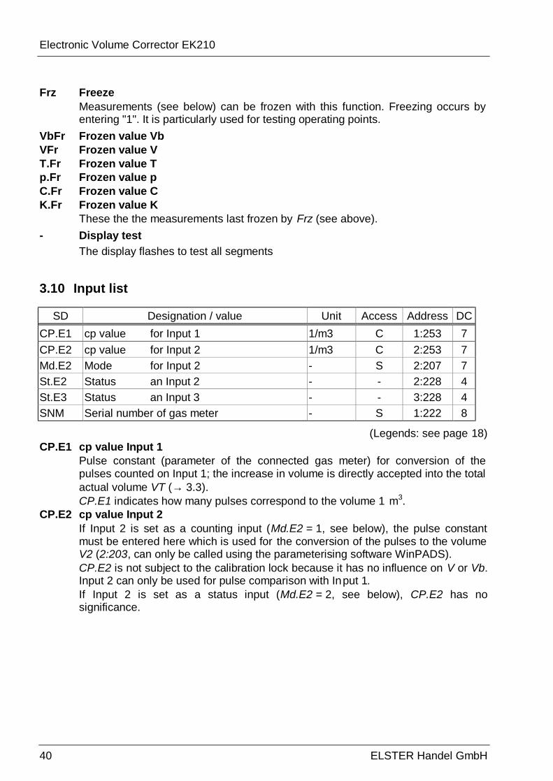
Frz Freeze Measurements (see below) can be frozen with this function. Freezing occurs by entering "1". It is particularly used for testing operating points.
VbFr Frozen value Vb VFr Frozen value V T.Fr Frozen value T p.Fr Frozen value p C.Fr Frozen value C K.Fr Frozen value K
These the the measurements last frozen by Frz (see above).
- Display test The display flashes to test all segments
3.10 Input list
SD Designation / value Unit Access Address DC CP.E1 cp value for Input 1 1/m3 C 1:253 7 CP.E2 cp value for Input 2 1/m3 C 2:253 7 Md.E2 Mode for Input 2 - S 2:207 7 St.E2 Status an Input 2 - - 2:228 4 St.E3 Status an Input 3 - - 3:228 4 SNM Serial number of gas meter - S 1:222 8
(Legends: see page 18) CP.E1 cp value Input 1
Pulse constant (parameter of the connected gas meter) for conversion of the pulses counted on Input 1; the increase in volume is directly accepted into the total actual volume VT (→ 3.3). CP.E1 indicates how many pulses correspond to the volume 1 m3.
CP.E2 cp value Input 2 If Input 2 is set as a counting input (Md.E2 = 1, see below), the pulse constant must be entered here which is used for the conversion of the pulses to the volume V2 (2:203, can only be called using the parameterising software WinPADS). CP.E2 is not subject to the calibration lock because it has no influence on V or Vb. Input 2 can only be used for pulse comparison with Input 1. If Input 2 is set as a status input (Md.E2 = 2, see below), CP.E2 has no significance.
Electronic Volume Corrector EK210
ELSTER HANDEL GmbH 41
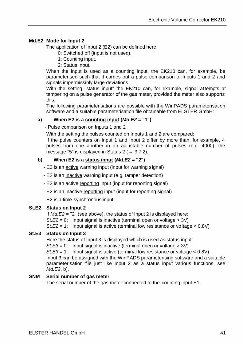
Md.E2 Mode for Input 2 The application of Input 2 (E2) can be defined here. 0: Switched off (input is not used). 1: Counting input. 2: Status input. When the input is used as a counting input, the EK210 can, for example, be parameterised such that it carries out a pulse comparison of Inputs 1 and 2 and signals impermissibly large deviations. With the setting "status input" the EK210 can, for example, signal at tempts at tampering on a pulse generator of the gas meter, provided the meter also supports this. The following parameterisations are possible with the WinPADS parameterisation software and a suitable parameterisation file obtainable from ELSTER GmbH:
a) When E2 is a counting input (Md.E2 = "1") - Pulse comparison on Inputs 1 and 2
With the setting the pulses counted on Inputs 1 and 2 are compared: If the pulse counters on Input 1 and Input 2 differ by more than, for example, 4 pulses from one another in an adjustable number of pulses (e.g. 4000), the message "5" is displayed in Status 2 (→ 3.7.2).
b) When E2 is a status input (Md.E2 = "2") - E2 is an active warning input (input for warning signal) - E2 is an inactive warning input (e.g. tamper detection) - E2 is an active reporting input (input for reporting signal) - E2 is an inactive reporting input (input for reporting signal) - E2 is a time-synchronous input
St.E2 Status on Input 2 If Md.E2 = "2" (see above), the status of Input 2 is displayed here: St.E2 = 0: Input signal is inactive (terminal open or voltage > 3V) St.E2 = 1: Input signal is active (terminal low resistance or voltage < 0.8V)
St.E3 Status on Input 3 Here the status of Input 3 is displayed which is used as status input: St.E3 = 0: Input signal is inactive (terminal open or voltage > 3V) St.E3 = 1: Input signal is active (terminal low resistance or voltage < 0.8V) Input 3 can be assigned with the WinPADS parameterising software and a suitable parameterisation file just like Input 2 as a status input various functions, see Md.E2, b).
SNM Serial number of gas meter The serial number of the gas meter connected to the counting input E1.
Electronic Volume Corrector EK210
42 ELSTER Handel GmbH
3.11 Output list
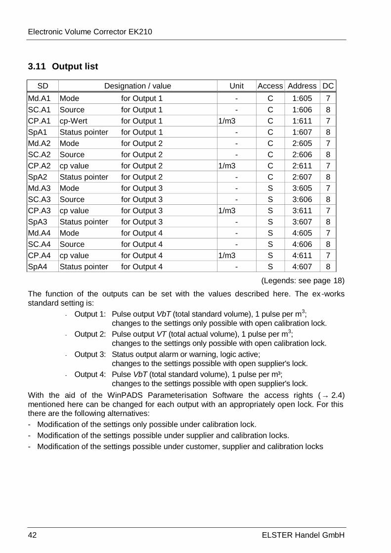
SD Designation / value Unit Access Address DC Md.A1 Mode for Output 1 - C 1:605 7 SC.A1 Source for Output 1 - C 1:606 8 CP.A1 cp-Wert for Output 1 1/m3 C 1:611 7 SpA1 Status pointer for Output 1 - C 1:607 8 Md.A2 Mode for Output 2 - C 2:605 7 SC.A2 Source for Output 2 - C 2:606 8 CP.A2 cp value for Output 2 1/m3 C 2:611 7 SpA2 Status pointer for Output 2 - C 2:607 8 Md.A3 Mode for Output 3 - S 3:605 7 SC.A3 Source for Output 3 - S 3:606 8 CP.A3 cp value for Output 3 1/m3 S 3:611 7 SpA3 Status pointer for Output 3 - S 3:607 8 Md.A4 Mode for Output 4 - S 4:605 7 SC.A4 Source for Output 4 - S 4:606 8 CP.A4 cp value for Output 4 1/m3 S 4:611 7 SpA4 Status pointer for Output 4 - S 4:607 8
(Legends: see page 18)
The function of the outputs can be set with the values described here. The ex-works standard setting is:
- Output 1: Pulse output VbT (total standard volume), 1 pulse per m3; changes to the settings only possible with open calibration lock.
- Output 2: Pulse output VT (total actual volume), 1 pulse per m3; changes to the settings only possible with open calibration lock.
- Output 3: Status output alarm or warning, logic active; changes to the settings possible with open supplier's lock.
- Output 4: Pulse VbT (total standard volume), 1 pulse per m³; changes to the settings possible with open supplier's lock.
With the aid of the WinPADS Parameterisation Software the access rights (→ 2.4) mentioned here can be changed for each output with an appropriately open lock. For this there are the following alternatives: - Modification of the settings only possible under calibration lock. - Modification of the settings possible under supplier and calibration locks. - Modification of the settings possible under customer, supplier and calibration locks
Electronic Volume Corrector EK210
ELSTER HANDEL GmbH 43
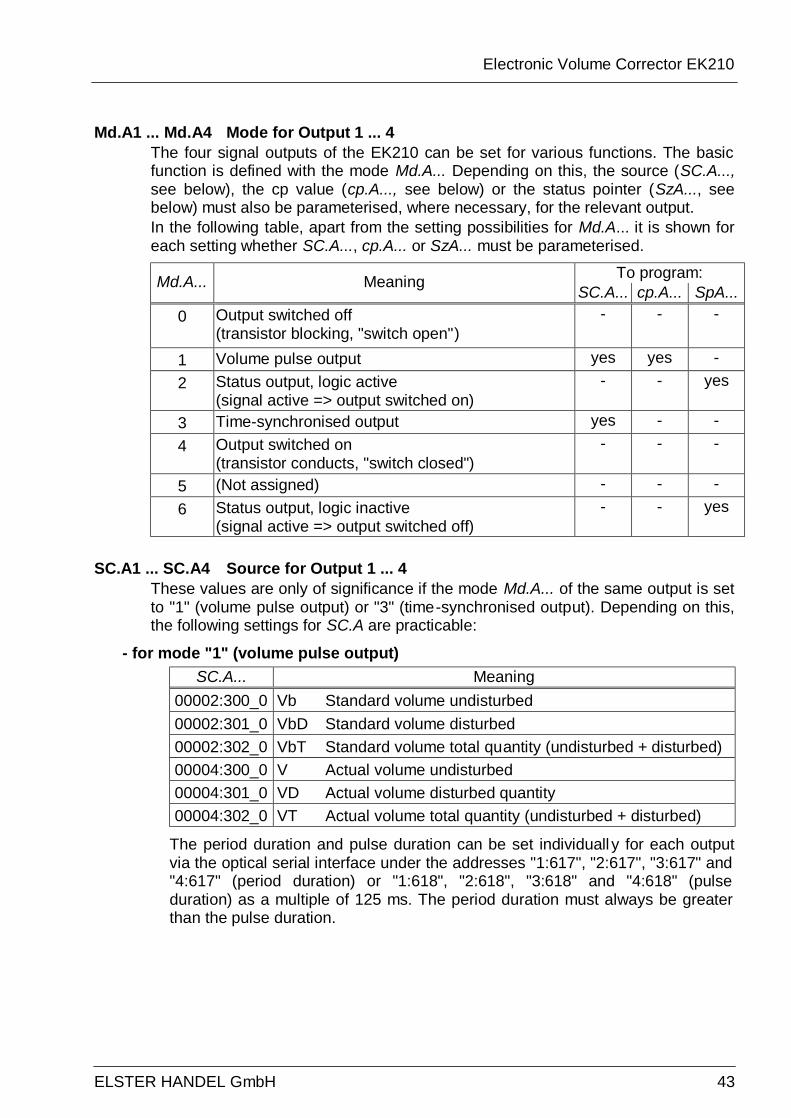
Md.A1 ... Md.A4 Mode for Output 1 ... 4 The four signal outputs of the EK210 can be set for various functions. The basic function is defined with the mode Md.A... Depending on this, the source (SC.A..., see below), the cp value (cp.A..., see below) or the status pointer (SzA..., see below) must also be parameterised, where necessary, for the relevant output. In the following table, apart from the setting possibilities for Md.A... it is shown for each setting whether SC.A..., cp.A... or SzA... must be parameterised.
To program: Md.A... Meaning SC.A... cp.A... SpA... 0 Output switched off
(transistor blocking, "switch open") - - -
1 Volume pulse output yes yes - 2 Status output, logic active
(signal active => output switched on) - - yes
3 Time-synchronised output yes - - 4 Output switched on
(transistor conducts, "switch closed") - - -
5 (Not assigned) - - - 6 Status output, logic inactive
(signal active => output switched off) - - yes
SC.A1 ... SC.A4 Source for Output 1 ... 4
These values are only of significance if the mode Md.A... of the same output is set to "1" (volume pulse output) or "3" (time-synchronised output). Depending on this, the following settings for SC.A are practicable:
- for mode "1" (volume pulse output) SC.A... Meaning
00002:300_0 Vb Standard volume undisturbed 00002:301_0 VbD Standard volume disturbed 00002:302_0 VbT Standard volume total quantity (undisturbed + disturbed) 00004:300_0 V Actual volume undisturbed 00004:301_0 VD Actual volume disturbed quantity 00004:302_0 VT Actual volume total quantity (undisturbed + disturbed)
The period duration and pulse duration can be set individuall y for each output via the optical serial interface under the addresses "1:617", "2:617", "3:617" and "4:617" (period duration) or "1:618", "2:618", "3:618" and "4:618" (pulse duration) as a multiple of 125 ms. The period duration must always be greater than the pulse duration.
Electronic Volume Corrector EK210
44 ELSTER Handel GmbH
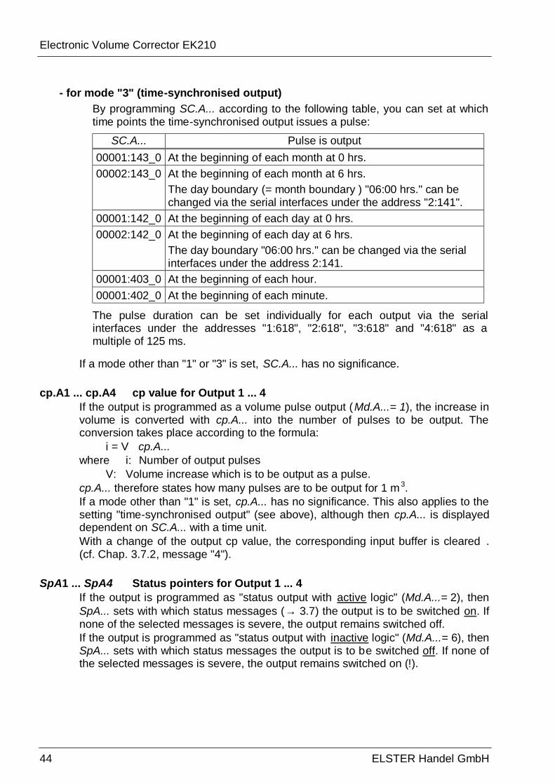
- for mode "3" (time-synchronised output) By programming SC.A... according to the following table, you can set at which time points the time-synchronised output issues a pulse:
SC.A... Pulse is output 00001:143_0 At the beginning of each month at 0 hrs. 00002:143_0 At the beginning of each month at 6 hrs.
The day boundary (= month boundary ) "06:00 hrs." can be changed via the serial interfaces under the address "2:141".
00001:142_0 At the beginning of each day at 0 hrs. 00002:142_0 At the beginning of each day at 6 hrs.
The day boundary "06:00 hrs." can be changed via the serial interfaces under the address 2:141.
00001:403_0 At the beginning of each hour. 00001:402_0 At the beginning of each minute.
The pulse duration can be set individually for each output via the serial interfaces under the addresses "1:618", "2:618", "3:618" and "4:618" as a multiple of 125 ms.
If a mode other than "1" or "3" is set, SC.A... has no significance. cp.A1 ... cp.A4 cp value for Output 1 ... 4
If the output is programmed as a volume pulse output (Md.A...= 1), the increase in volume is converted with cp.A... into the number of pulses to be output. The conversion takes place according to the formula: i = V û cp.A... where i: Number of output pulses V: Volume increase which is to be output as a pulse. cp.A... therefore states how many pulses are to be output for 1 m 3. If a mode other than "1" is set, cp.A... has no significance. This also applies to the setting "time-synchronised output" (see above), although then cp.A... is displayed dependent on SC.A... with a time unit. With a change of the output cp value, the corresponding input buffer is cleared . (cf. Chap. 3.7.2, message "4").
SpA1 ... SpA4 Status pointers for Output 1 ... 4
If the output is programmed as "status output with active logic" (Md.A...= 2), then SpA... sets with which status messages (→ 3.7) the output is to be switched on. If none of the selected messages is severe, the output remains switched off. If the output is programmed as "status output with inactive logic" (Md.A...= 6), then SpA... sets with which status messages the output is to be switched off. If none of the selected messages is severe, the output remains switched on (!).
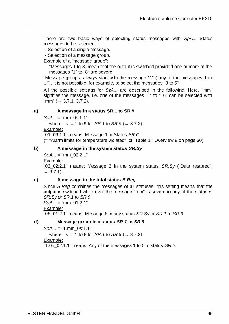
Electronic Volume Corrector EK210
ELSTER HANDEL GmbH 45
There are two basic ways of selecting status messages with SpA... Status messages to be selected: - Selection of a single message. - Selection of a message group. Example of a "message group":
"Messages 1 to 8" mean that the output is switched provided one or more of the messages "1" to "8" are severe.
"Message groups" always start with the message "1" ("any of the messages 1 to ..."). It is not possible, for example, to select the messages "3 to 5".
All the possible settings for SzA... are described in the following. Here, "mm" signifies the message, i.e. one of the messages "1" to "16" can be selected with "mm" (→ 3.7.1, 3.7.2).
a) A message in a status SR.1 to SR.9 SpA... = "mm_0s:1.1"
where s = 1 to 9 for SR.1 to SR.9 (→ 3.7.2) Example: "01_06:1.1" means: Message 1 in Status SR.6 (= "Alarm limits for temperature violated", cf. Table 1: Overview 8 on page 30)
b) A message in the system status SR.Sy SpA... = "mm_02:2.1" Example: "03_02:2.1" means: Message 3 in the system status SR.Sy ("Data restored", → 3.7.1).
c) A message in the total status S.Reg Since S.Reg combines the messages of all statuses, this setting means that the output is switched while ever the message "mm" is severe in any of the statuses SR.Sy or SR.1 to SR.9. SpA... = "mm_01:2.1" Example: "08_01:2.1" means: Message 8 in any status SR.Sy or SR.1 to SR.9.
d) Message group in a status SR.1 to SR.9 SpA... = "1.mm_0s:1.1"
where s = 1 to 8 for SR.1 to SR.9 (→ 3.7.2) Example: "1.05_02:1.1" means: Any of the messages 1 to 5 in status SR.2.
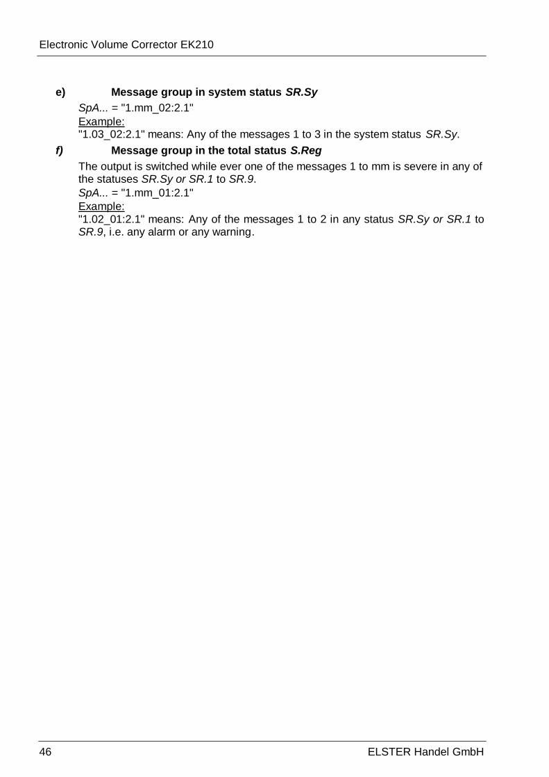
Electronic Volume Corrector EK210
46 ELSTER Handel GmbH
e) Message group in system status SR.Sy SpA... = "1.mm_02:2.1" Example: "1.03_02:2.1" means: Any of the messages 1 to 3 in the system status SR.Sy.
f) Message group in the total status S.Reg The output is switched while ever one of the messages 1 to mm is severe in any of the statuses SR.Sy or SR.1 to SR.9. SpA... = "1.mm_01:2.1" Example: "1.02_01:2.1" means: Any of the messages 1 to 2 in any status SR.Sy or SR.1 to SR.9, i.e. any alarm or any warning.
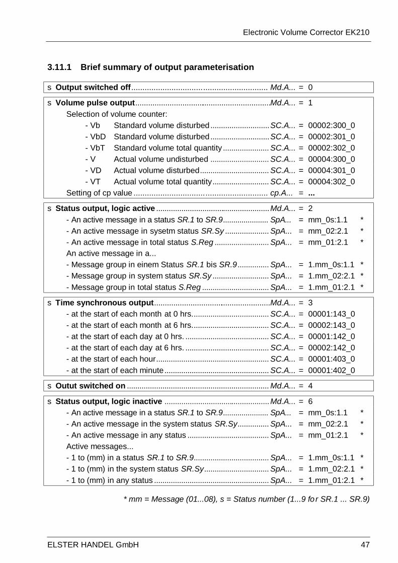
Electronic Volume Corrector EK210
ELSTER HANDEL GmbH 47
3.11.1 Brief summary of output parameterisation
s Output switched off............................................................. Md.A... = 0
s Volume pulse output................................................................Md.A... = 1 Selection of volume counter: - Vb Standard volume disturbed............................SC.A... = 00002:300_0 - VbD Standard volume disturbed............................SC.A... = 00002:301_0 - VbT Standard volume total quantity ...................... SC.A... = 00002:302_0 - V Actual volume undisturbed ............................ SC.A... = 00004:300_0 - VD Actual volume disturbed................................. SC.A... = 00004:301_0 - VT Actual volume total quantity........................... SC.A... = 00004:302_0 Setting of cp value ............................................................ cp.A... = ...
s Status output, logic active ......................................................Md.A... = 2 - An active message in a status SR.1 to SR.9...................... SpA... = mm_0s:1.1 * - An active message in sysetm status SR.Sy ..................... SpA... = mm_02:2.1 * - An active message in total status S.Reg .......................... SpA... = mm_01:2.1 * An active message in a... - Message group in einem Status SR.1 bis SR.9............... SpA... = 1.mm_0s:1.1 * - Message group in system status SR.Sy ........................... SpA... = 1.mm_02:2.1 * - Message group in total status S.Reg ................................ SpA... = 1.mm_01:2.1 *
s Time synchronous output.......................................................Md.A... = 3 - at the start of each month at 0 hrs..................................... SC.A... = 00001:143_0 - at the start of each month at 6 hrs..................................... SC.A... = 00002:143_0 - at the start of each day at 0 hrs. ........................................ SC.A... = 00001:142_0 - at the start of each day at 6 hrs. ........................................ SC.A... = 00002:142_0 - at the start of each hour...................................................... SC.A... = 00001:403_0 - at the start of each minute.................................................. SC.A... = 00001:402_0
s Outut switched on .................................................................... Md.A... = 4
s Status output, logic inactive ..................................................Md.A... = 6 - An active message in a status SR.1 to SR.9...................... SpA... = mm_0s:1.1 * - An active message in the system status SR.Sy............... SpA... = mm_02:2.1 * - An active message in any status ....................................... SpA... = mm_01:2.1 * Active messages... - 1 to (mm) in a status SR.1 to SR.9.................................... SpA... = 1.mm_0s:1.1 * - 1 to (mm) in the system status SR.Sy............................... SpA... = 1.mm_02:2.1 * - 1 to (mm) in any status ....................................................... SpA... = 1.mm_01:2.1 *
* mm = Message (01...08), s = Status number (1...9 fo r SR.1 ... SR.9)
Electronic Volume Corrector EK210
48 ELSTER Handel GmbH
3.12 Archives
The EK210 has three archives - Month Archive 1 (counter readings and maxima) - Logbook (event logbook) - Changes logbook (audit trail) All archives cannot be displayed on the device. They can be read out with the AS-200 Readout Device or the WinPADS parameterisation software.
3.12.1 Month Archive 1 (counter readings and maxima) The counter readings and consumption maxima of the last 15 months are sav ed in Month Archive 1. The day boundary (= month boundary ) "06:00 hrs." can be changed via the serial interfaces under the address 2:141. Each archive data row has the following entries: • AONo Block number • Time Storage time-point • Vb Standard volume • VbT Totaliser Vb • VbMP max Month maximum VbMP • Time Time-point VbMP max • Stat Status for VbMP max • VbDy max Month maximum VbDy • Time Time-point VbDy max • Stat Status for VbDy max • V Actual volume
• VT1 Totaliser Input 1 • VMP max Month maximum VMP • Time Time-point VMP max • Stat Status for VMP max • VDy max Month maximum VDy • Time Time-point VDy max • Stat Status for VDy max • St.2 Status 2 (incl. Vb) • St.4 Status 4 (incl. V) • Er.Ch Checksum
3.12.2 Logbook (event logbook) Here, the last 250 status changes are archived. Each archive data row has the following entries: • AONo Block number • Time Storage time-point • St.Ae Trigger event • Er.Ch Checksum
3.12.3 Changes logbook (audit trail) Here, the last 200 settings changes (parameterisations) are arch ived. Each archive data row has the following entries: • AONo Block number • Time Storage time-point • Adr Address of the changed value • Old Old value • New New value
• St.CL Calibration lock • St.ML Manufacturer's lock • St.SL Supplier's lock • St.KL Customer's lock • Er.Ch Checksum
Electronic Volume Corrector EK210
ELSTER HANDEL GmbH 49
4 Applications
4.1 Application in areas subject to explosion hazards
4.1.1 Applications in Zone 1 The EK210 is suitable for applications in Ex Zone 1 for gases in the temperature class T4 (ignition temperature > 135°C, e.g. natural gas). (Certificate of conformance: à Appendix A-2). With applications in Zone 1 connected devices must not exceed the conditions and limits quoted in the certificate of conformance (à A-2). Furthermore, all safety information (à Chapter I) must be followed.
4.1.2 Applications in Zone 2 The device may also be used in Zone 2 under all conditions which enable application in Zone 1 (à 4.1). Furthermore, the device may be used according to DIN EN 60079-14 (VDE 0165 Part 1), Section 5.2.3 c) in Zone 2 for gases of temperature class T1 (e.g. natural gas) if the installation is implemented according to DIN EN 60079-14 (VDE 0165 Part 1) and the operating conditions quoted in these instructions are fulfilled . In particular they are:
• Ambient temperature according to Chapter B-1. • Batteries according to Chapter B-2. • Correct wiring, in particular no active outputs switching one against the other. • Switching of the digital inputs DE1...DE3 according to Chapter B-3 only with reed
contacts or transistor switches. • Switching voltage of the device connected to the outputs DA1..DA4 with a maximum
of 30 V according to Chapter B-4 (manufacturer's rating of the connected devices). • Unused cable glands must be closed off according to DIN EN 60079-14 (VDE 0165
Part 1), Section 14.3.2 with plugs or suitable screw caps. • Installation, cables and lines according to DIN EN 60079-14 (VDE 0165 Part 1), in
particular Sections 9, 12.1, 12.2 and 14.3.

Electronic Volume Corrector EK210
50 ELSTER Handel GmbH
5 Installation and maintenance
The EK210 is suitable for wall or pipe mounting and for installation on a gas meter. The holes for wall mounting become accessible after opening the housing cover. For installation on a meter a mounting bracket is required and for a pipe installation a mounting bracket with a pipe clamp is needed. The installation and first test can occur without the presence of a calibration official, because all relevant areas are secured by adhesive labels.
5.1 Installation procedure
The following steps must be carried out to install the device: 1. Mounting of the EK210 on the gas meter, a bracket, a pipe or on the wall. 2. Connection of the pulse generator, pressure line and insertion of the temperature
sensor in the temperature sensor receptacle. 3. If required, connection of following devices to, for example, pulse/signal outputs. F If the EK210 is used in an area subject to explosive atmospheres (Zone 1), then only
intrinsically safe electrical circuits of certificated "associated operating equipment" must be connected. Their certificated electrical data must conform to the requirements stated in the certificate of conformance for the EK210.
4. With unused union screw joints the insertion seal must be replaced by one the enclosed blind insertion seals.
5. Sealing of the device by the weights and measures office or test station according to the seal layout.
6. Close the housing. F When closing the housing, make sure that no cables are pinched.
Electronic Volume Corrector EK210
ELSTER HANDEL GmbH 51
5.2 Cable connection and earthing
The EK210 housing must always be earthed in order to divert high energy and high voltage electromagnetic interference. An M6 screw is provided for this on the left -hand side of the housing. The earthing must be low resistance. The best condi tions are obtained when a direct connection is provided to the local potential equalisation strip through a cable which is as short and as thick (at least 4mm²) as possible. All permanently connected cables have a screen which must be earthed at both ends to prevent interference due to high frequency electromagnetic fields. The screen must be connected all round, complete and flat. The EK210 has special EMC cable glands for this purpose. With correct connection of the cable screens and correct laying of th e cables effects due to circulation should not be expected. If, however, interference due to earthing points with potential differences occurs, potential equalisation lines can be laid in parallel to the cables. These should then be connected as close as possible to the cable screen connection points.

Electronic Volume Corrector EK210
52 ELSTER Handel GmbH
5.3 Terminal layout
Connection of the individual cables is made to the corresponding terminals on the circuit board in the housing cover. When positioning the cables, make sure that no cables are pinched as the cover is closed.
Gehäuse-Deckel(Innenansicht)
DE1+
X14
X13 -DA1DE2 DE3
+- +- -DA2 DA3
+ +- +-X35 X85
DA4+-
X84
Fig. 1: Terminal layout
Inputs: DE1 Digital input 1 for pulse generator DE2 Digital input 2 DE3 Digital input 3
Outputs: DA1 Digital output 1 (can be sealed) DA2 Digital output 2 (can be sealed) DA3 Digital output 3 DA4 Digital output 4
Housing cover (internal view)
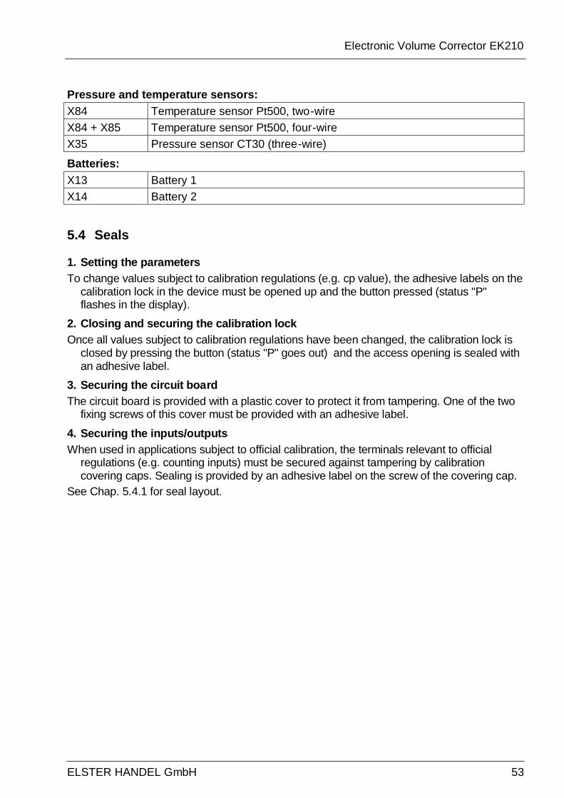
Electronic Volume Corrector EK210
ELSTER HANDEL GmbH 53
Pressure and temperature sensors: X84 Temperature sensor Pt500, two-wire X84 + X85 Temperature sensor Pt500, four-wire X35 Pressure sensor CT30 (three-wire)
Batteries: X13 Battery 1 X14 Battery 2
5.4 Seals
1. Setting the parameters To change values subject to calibration regulations (e.g. cp value), the adhesive labels on the
calibration lock in the device must be opened up and the button pressed (status "P" flashes in the display).
2. Closing and securing the calibration lock Once all values subject to calibration regulations have been changed, the calibration lock is
closed by pressing the button (status "P" goes out) and the access opening is sealed with an adhesive label.
3. Securing the circuit board The circuit board is provided with a plastic cover to protect it from tampering. One of the two
fixing screws of this cover must be provided with an adhesive label.
4. Securing the inputs/outputs When used in applications subject to official calibration, the terminals relevant to official
regulations (e.g. counting inputs) must be secured against tampering by calibration covering caps. Sealing is provided by an adhesive label on the screw of the covering cap.
See Chap. 5.4.1 for seal layout.
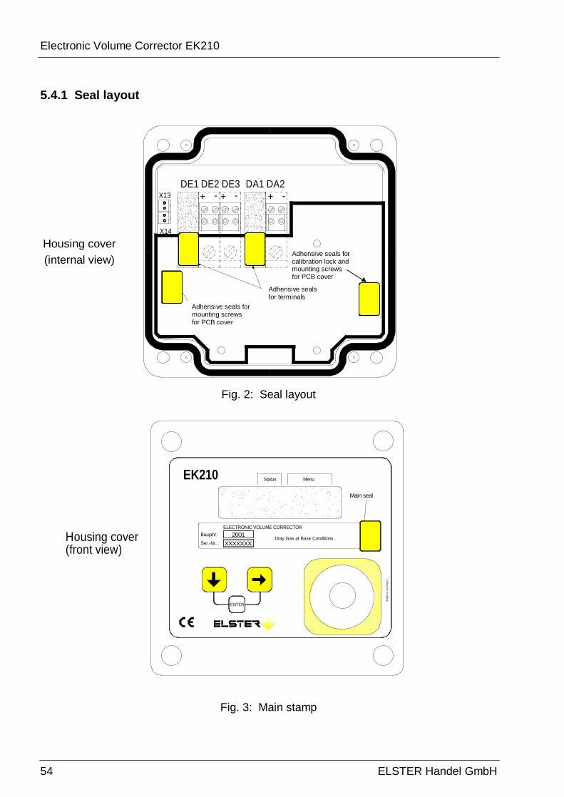
Electronic Volume Corrector EK210
54 ELSTER Handel GmbH
5.4.1 Seal layout
Klebeplomben für Befestigungsschraubeder Leiterkarten-Abdeckung
DE2
Gehäuse-Deckel(Innenansicht) GF 2
01
GF 2
01
X14
X13 + -DE1
Klebeplombe fürBefestigungsschraubeder Leiterkarten-Abdeckungund Eichschalter
GF 201
Klebeplombenfür Klemmen
GF 2
01
-+ + -DA1DE3 DA2
Fig. 2: Seal layout
Fig. 3: Main stamp
Main seal
ENTER
XXXXXXX2001
ELECTRONIC VOLUME CORRECTORBaujahr:
Ser.-Nr.:Housing cover(front view)
Mad
e in
Ger
man
y
Dray Gas at Base Conditions
EK210 MenuStatus
Housing cover (internal view)
Adhensive seals for mounting screws for PCB cover
Adhensive seals for terminals
Adhensive seals for calibration lock and mounting screws for PCB cover

Electronic Volume Corrector EK210
ELSTER HANDEL GmbH 55
5.5 Battery replacement
During operation a check must be made from time to time of whether t he battery needs to be replaced. For this, the battery warning "B" in the "Status" field of the display is used (→ 2.2.1) as well as the remaining battery life in the service list (→ 3.9: Bat.R).
F In the standard operating case (→ B-2 Battery) the operating period with one battery is at least 5 years. The operating period may reduce due to different modes of operation. For further details → 3.9: Bat.R and Bat.C
F Battery replacement can be carried out without the present of a calibration official, because the housing itself is not sealed.
F During battery replacement at least one battery should always remain connected. Before the old battery is removed, the new battery must be connected. A total of two plugs are provided for this.
F EK210 measurements may be lost due to careless procedures. All the set parameters, along with the once-daily date, time and counter readings are saved in a non-volatile memory (EEPROM) and automatically recalled when required.
F As an additional backup, all data should be saved in the non-volatile memory (EEPROM) directly before battery replacement (→ 3.9, "Save"). If, due to an operating fault during battery replacement, data is lost, the EK210 automatically recalls the data from the time it was previously saved.
F Replacement should only be carried out by ELSTER Service or by specially trained personnel.

Electronic Volume Corrector EK210
56 ELSTER Handel GmbH
5.5.1 Carrying out battery replacement
1. Carry out a data backup as a precautionary measure (→ 3.9: Save). 2. Open up the housing cover and swivel downwards. The battery in the bottom part of
the housing is then accessible.
3. Check the type and order number of the new batteries.
C Tip: Mark the old battery, e.g. with a felt-tip pen or sticker before you start the battery replacement. This avoids any later confusion.
4. At least one battery must always be connected to one of the two plugs. If this is not the case, volume pulses may be lost during the battery replacement and the clock may be slow after battery replacement.
5. Remove the retaining clip on the battery holder.
6. Insert the new battery and connect to the free plug in parallel to the old battery (both are electrically isolated). The plugs are polarised against incorrect connection.
7. Pull off the old battery from the plug and remove.
8. Fit the retaining clip on the battery holder.
9. Reclose the housing (make sure that the cable is not pinched).
10. Under "Service" - "Battery capacity" (→ 3.9: BAT.K) the initial capacity must be entered (essential even with the same capacity value)! With the use of the battery obtainable from ELSTER GmbH of size "D", the value 13 Ah should be entered for Bat.C and 26.0 Ah when 2 cells are used.
11. Check the operating life calculated by the EK210:Bat.R (→ 3.9).
12. End of the battery replacement.

Electronic Volume Corrector EK210
ELSTER HANDEL GmbH 57
A Approvals
A.1 EC Declaration of Conformance

Electronic Volume Corrector EK210
58 ELSTER Handel GmbH
(Translation of German document)
EC Declaration of Conformance
according to the "Law on the electromagnetic compatibility of equipment (EMCL)" and the EMC Directive 89/336/EWG of the Council of 3rd May 1989 (EMC Directive) as well as
Articles 5 and 14 of the Directive 93/68/EWG of the Council of 22nd July 1993 about the modification of Directive 89/336/EWG.
No.______KCE106____________ Supplier: ELSTER GmbH Address: Steinernstraße 19-21 D-55252 Mainz-Kastel Product: State Volume Corrector Type EK210 The product described above conforms to: Document No. Title Issue/Date
of Issue DIN EN 6100-6-2 Interference immunity for industrial sector 2000 DIN EN 50082-1 Interference immunity for residential, business and
commercial sectors 1997
DIN EN 55011 Class B
Interference emission on ISM devices 2000
DIN EN 50081-2 Interference immunity for industrial sector 1994 Additional details Mainz-Kastel, 17.10.2001 (Place and date of issue) O. Pfaff, Manager of Electronic System Development (Name, function) (Signature)
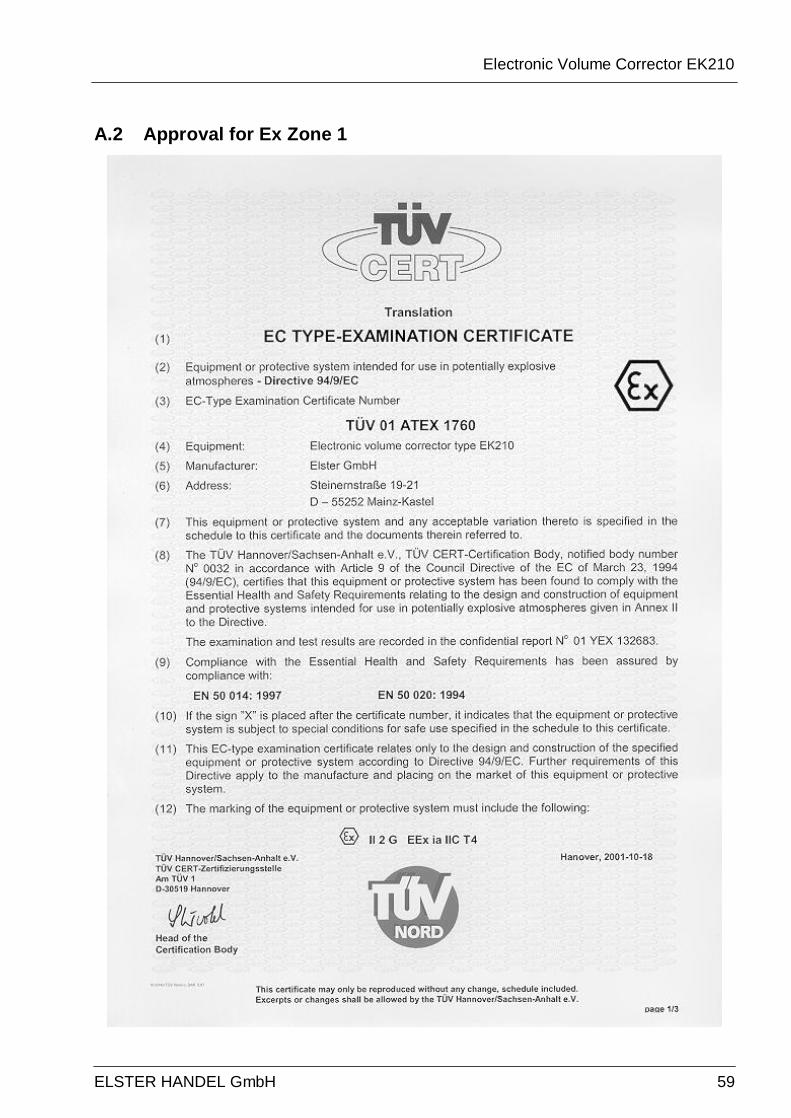
Electronic Volume Corrector EK210
ELSTER HANDEL GmbH 59
A.2 Approval for Ex Zone 1
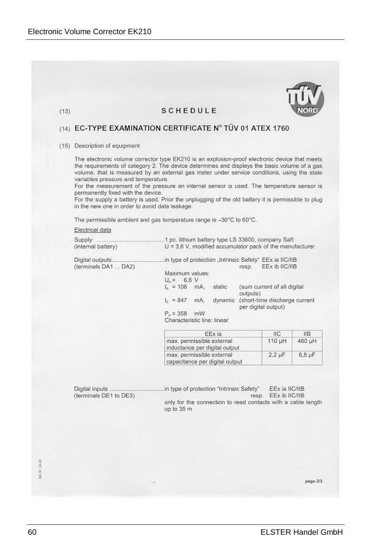
Electronic Volume Corrector EK210
60 ELSTER Handel GmbH
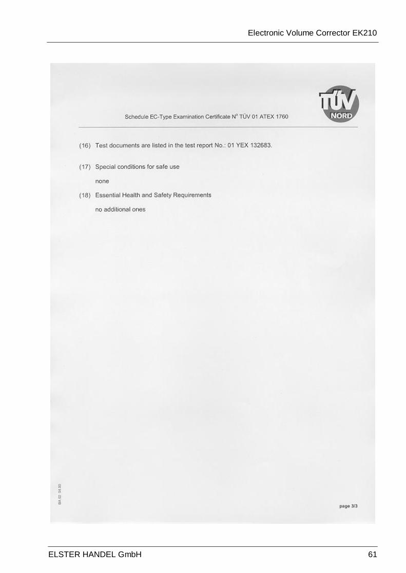
Electronic Volume Corrector EK210
ELSTER HANDEL GmbH 61
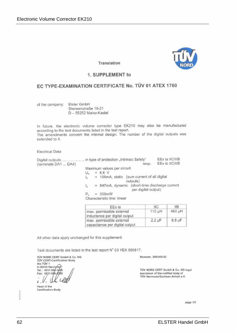
Electronic Volume Corrector EK210
62 ELSTER Handel GmbH
Electronic Volume Corrector EK210
ELSTER HANDEL GmbH 63
B Technical data B-1 General data (mechanical)
Housing/construction Wall-mounted housing; aluminium cast alloy G AI SI 12 / DIN 1775; cable entries
Dimensions (W x H x T) approx. 126 x 120 x 90 mm (with cable entry glands)
Weight approx. 1.7 kg Protection IP 66 according to EN60529 Ambient temperature -20°C ... +60 °C Climatic conditions Suitable for outside installation
B-2 Battery
Battery 1 lithium battery; 3.6V; size D normal rated capacity: 16.5 Ah Usable capacity for EK210: 13.0 Ah Order no.: 73015774
1 additional lithium batteries optional for double service life Order no.: 73015774
The minimum operating life of 5 years with two batteries is guaranteed for the following standard operating case: Measurement cycle 20 s Operating cycle 300 s (5 minutes) Mode for Input 1 1 (pulse input) Display active 1 hour per month Interface active 15 minutes per month Ambient temperature TA = -10...+50 °C
Electronic Volume Corrector EK210
64 ELSTER Handel GmbH
B-3 Pulse and status inputs
Three digital inputs with common ground (minus pole) for reed contacts or transistor switches. Designation DE1... DE3 Cable connection Plug-in terminals; 0.5 ... 1.5 mm²
With flexible cable use wire-end sleeves. Screening Connect cable screen to the cable gland over the full area. Special features Each input can be parameterised and sealed separately. Nominal data
F For data which is not mentioned here, the limits in the certificate of conformance must be observed when using the EK210 in Ex Zone 1.
Open-circuit voltage U0 ≈ 2 V Internal resistance Ri ≈ 500 kΩ Short circuit current Ik ≈ 4 µA Switching level "on" Re ≤ 100 kΩ or Ue < 0,8 V Switching level "off" Ra ≥ 2 MΩ Pulse duration te ≥ 50 ms Space duration ta ≥ 50 ms Counting frequency f ≤ 10 Hz
B-4 Signal and pulse outputs
Four transistor outputs with common ground (minus pole). The volume pulses acquired for one measurement cycle are output as pulse packets. They are therefore not suitable for open and closed-loop control purposes.
Designation DA1... DA4 Cable connection Plug-in terminals; 0.5 ... 1.5 mm²
With flexible cable use wire-end sleeves. Screening Connect cable screen to the cable gland over the full area. Special features All outputs can be parameterised separately and Outputs
A1 and A2 can be sealed using calibration labels. Nominal data:
F For data which is not mentioned here, the limits in the certificate of conformance must be observed when using the EK210 in Ex Zone 1.
Maximum switching voltage 30 V DC Maximum switching current 50 mA DC Maximum voltage drop 1V Maximum residual current 0.001 mA Pulse duration Min. 125 ms, adjustable on a pitch of 125 ms Space duration Min. 125 ms, adjustable on a pitch of 125 ms Output frequency Max. 4 Hz, adjustable
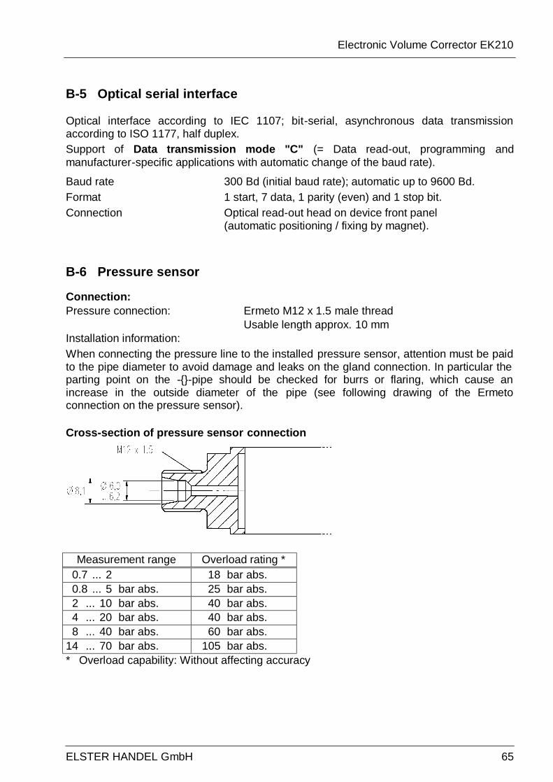
Electronic Volume Corrector EK210
ELSTER HANDEL GmbH 65
B-5 Optical serial interface
Optical interface according to IEC 1107; bit-serial, asynchronous data transmission according to ISO 1177, half duplex. Support of Data transmission mode "C" (= Data read-out, programming and manufacturer-specific applications with automatic change of the baud rate).
Baud rate 300 Bd (initial baud rate); automatic up to 9600 Bd. Format 1 start, 7 data, 1 parity (even) and 1 stop bit. Connection Optical read-out head on device front panel
(automatic positioning / fixing by magnet).
B-6 Pressure sensor
Connection: Pressure connection: Ermeto M12 x 1.5 male thread Usable length approx. 10 mm Installation information: When connecting the pressure line to the installed pressure sensor, attention must be paid to the pipe diameter to avoid damage and leaks on the gland connection. In particular the parting point on the --pipe should be checked for burrs or flaring, which cause an increase in the outside diameter of the pipe (see following drawing of the Ermeto connection on the pressure sensor). Cross-section of pressure sensor connection
Measurement range Overload rating * 0.7 ... 2 18 bar abs. 0.8 ... 5 bar abs. 25 bar abs. 2 ... 10 bar abs. 40 bar abs. 4 ... 20 bar abs. 40 bar abs. 8 ... 40 bar abs. 60 bar abs. 14 ... 70 bar abs. 105 bar abs. * Overload capability: Without affecting accuracy
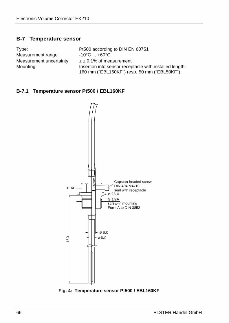
Electronic Volume Corrector EK210
66 ELSTER Handel GmbH
B-7 Temperature sensor
Type: Pt500 according to DIN EN 60751 Measurement range: -10°C ... +60°C Measurement uncertainty: ≤ ± 0.1% of measurement Mounting: Insertion into sensor receptacle with installed length:
160 mm ("EBL160KF") resp. 50 mm ("EBL50KF")
B-7.1 Temperature sensor Pt500 / EBL160KF
19AF
Capstan-headed screwDIN 404 M4x10seal with receptacle
G 1/2Ascrew-in mountingForm A to DIN 3852
Fig. 4: Temperature sensor Pt500 / EBL160KF

Electronic Volume Corrector EK210
ELSTER HANDEL GmbH 67
B-7.2 Temperature sensor Pt500 / EBL50KF
87.5
73.0
113.
0
Fig. 5: Temperature sensor Pt500 / EBL50KF
B-8 Measurement uncertainty
The error limits quoted in the calibration directive and in DIN EN 12405 are maintained. Depending on the ambient temperature and the pressure measurement range , detailed data is available on request.
Electronic Volume Corrector EK210
68 ELSTER Handel GmbH
C Index
A Alarm · 19, 20, 21, 46 Alarm limits · 22, 23, 24, 25, 30, 34, 35, 45 Ambient temperature · 37, 67 Area subject to explosive atmospheres · 50 Associated operating equipment · 50
B Battery · 6, 29, 37, 38, 55 Battery capacity · 38, 39, 56 Battery life · 29, 36, 37, 38, 39 Battery replacement · 29, 39, 55
C Calibration lock · 14, 18, 34, 35, 39 Calibration switch · See Calibration lock Changes logbook · 48 Clear output pulse buffer · 44 Clear output pulse buffer · 31 Clock · 29
Running accuracy · 29
D Data backup · 29 Day boundary · 44, 48 Daylight saving · 30, 36
E Event logbook · 48 Ex Zone 1 · see Zone 1
F Freeze · 38, 40
I Interface · 14
L Logbook
Changes logbook · 48 Lower alarm limit pressure · 22 Lower alarm limit temperature · 24
M Month archive · 48 Month boundary · 48
P Pressure sensor · 22, 23, 65 Pulse comparison · 41
R Remaining battery service life · See Battery life
S Save data · 39 Signal input · 32, 41
T Tamper detection · 32 Temperature sensor · 24, 25, 66
U Upper alarm limit pressure · 22 Upper alarm limit temperature · 24
V Voltage failure · 29
W Warning · 46
Z Zone 1 · 49, 50


