QMP 7.5/RC-1 Rev.1 Channabasaveshwara Institute of Technology (NAAC Accredited & ISO 9001:2015 Certified Institution) NH 206 (B.H. Road), Gubbi, Tumkur – 572 216. Karnataka Department of Civil Engineering Concrete and Highway Materials Laboratory 17CVL58 B. E – V Semester (CBCS) Laboratory Manual 2019-20 Prepared by: Reviewed by: 1. Mr. Manjunatha M Katti Dr. Sudhi Kumar G S Asst. Professor Professor 2. Prathap G P Asst. Professor Approved by: Dr. Sudhi Kumar G S Professor& Head Department of Civil Engineering
Transcript
QMP 7.5/RC-1 Rev.1
Channabasaveshwara Institute of Technology (NAAC Accredited & ISO 9001:2015 Certified Institution)
THEORY: The tensile strength is one of the basic and important properties of the concrete. The
concrete is not usually expected to resist the direct tension because of its low tensile strength and
brittle nature. However, the determination of tensile strength of concrete is necessary to
determine the load at which the concrete members may crack. The cracking is a form of tension
failure.
PROCEDURE:
1. Take mix proportion as 1:2:4 with water cement ratio of 0.6. Take 21kg of coarse
aggregate, 10.5 kg of fine aggregate 5.25kg of cement and 3.l5 liters of water. Mix them
thoroughly until uniform colour is obtained. This material will be sufficient for casting
three cylinders of the size 150mm diameter X 300 mm length. In mixing by hand cement
and fine aggregate be first mixed dry to uniform colour and then coarse aggregate is
added and mixed until coarse aggregate is uniformly distributed throughout the batch.
Now the water shall be added and the ingredients are mixed until resulting concrete is
uniform in colour. Mix at least for two minutes.
2. Pour concrete in moulds oiled with medium viscosity oil. Fill the cylinder mould in four
layers each of approximately 75 mm and ram each layer more than 35 times with evenly
distributed strokes.
3. Remove the surplus concrete from the tope of the moulds with the help of the trowel.
4. Cover the moulds with wet mats and put the identification mark after about 3 to 4 hours.
5. Remove the specimens from the mould after 24 hours and immerse them in water for the
final curing. The test is usually conducted at the age of 7-28 days. The time age shall be
calculated from the time of addition of water to the dry ingredients.
6. Test at least three specimens for each age of test as follows
(i) Draw diametrical lines on two ends of the specimen so that they are in the same
axial plane.
Concrete and Highway Materials Laboratory 17CVL58
Dept of Civil Engg. CIT Gubbi Page 39
Concrete and Highway Materials Laboratory 17CVL58
Dept of Civil Engg. CIT Gubbi Page 40
I. Determine the diameter of specimen to the nearest 0.2 mm by averaging the diameters of
the specimen lying in the plane of premarked lines measured near the ends and the
middle of the specimen. The length of specimen also shall be taken be nearest 0.2 mm by
averaging the two lengths measured in the plane containing pre marked lines.
II. Centre one of the plywood strips along the centre of the lower platen. Place the specimen
on the plywood strip and align it so that the lines marked on the end of the specimen are
vertical and centered over the plywood strip. The second plywood strip is placed length
wise on the cylinder center on the lines marked on the ends of the cylinder.
III. The assembly is positioned to ensure that lines marked on the end of specimen are
vertical and the projection of the plane passing through these two lines interest the centre
of the platen.
Apply the load without shock and increase it continuously at the rate toproduce a split tensile
stress of approximately1.4 to 2.1 N/mm2/min, until nogreater load can be sustained. Record the
maximum load applied to specimen
Note the appearance of concrete and any unusual feature in the type of failure.
Compute the split tensile strength of the specimen to the nearest 0.25 N/mm2
PRECAUTIONS
The mould and base plate must be oiled lightly before use
The specimen should be made and cured as per IS 516-1959
The specimen should be tested immediately on removal from the water
The specimen should be placed in testing machine centrally
Load should be applied without shock
RESULT
Concrete and Highway Materials Laboratory 17CVL58
Dept of Civil Engg. CIT Gubbi Page 41
Sketch:
Flexural Testing on concrete
Result: The flexural strength of concrete is N/mm2
IS Specification:
Conclusion:
Reference Code: -
IS 7246 – 1974 Recommendations for use of table vibrators consolidating concrete
IS 4031 - part 7 - 1988 Method of test for strength of concrete
IS 269: 1967 Specifications for ordinary and low Portland cement
IS: 650 – 1966 Specification for standard sand for testing of cement
Concrete and Highway Materials Laboratory 17CVL58
Dept of Civil Engg. CIT Gubbi Page 42
Exp No: Date:
FLEXURAL STRENGTH TEST
Aim: To determine, the strength of concrete using flexural test
Apparatus: The following apparatus are required for the test.
1. Prism mould (15 cm x 15 cm x 70 cm)
2. Universal Testing Machine
Theory: Concrete is relatively strong in compression and weak in tension. In RCC concrete
members, little dependence is placed on tensile strength of concrete since steel reinforcing bars
are provided to resist all tensile forces. However, tensile stresses are likely to develop in concrete
due to drying shrinkage, rusting of steel reinforcement, temperature gradient and many other
reasons. Therefore, the knowledge of tensile strength of concrete is of importance.
Procedure:
1. Test specimens are stored in water at a temperature of 24o C to 30o C for 48 hours before
testing. They are tested immediately on removal from the water whilst they are still wet
condition.
2. The dimension of each specimen should be noted before testing.
3. The bearing surface of the supporting and loading rollers is wiped and clean, and any
loose sand or other material removed from the surfaces of the specimen where they are to
make contact with the rollers.
4. The specimen is then placed in the machine in such manner that the load is applied to the
upper most surface as cast in the mould
5. The axis of specimen is carefully aligned with the axis of the loading device. No packing
is used between the bearing surfaces of the specimen and rollers.
6. The load is applied without shock and increasing continuously at a rate of the specimen.
The rate of loading is 4kN/min for the 15cm specimen and 18 kN /min for the 10cm
specimen.
7. The load is increased until the specimen fails and the maximum load applied to the
specimen during the test is recorded
Concrete and Highway Materials Laboratory 17CVL58
Dept of Civil Engg. CIT Gubbi Page 43
NON-DESTRUCTIVE TEST
Introduction
Non-destructive testing (NDT) methods are techniques used to obtain information about the
properties or internal condition of an object without damaging the object. Non-destructive testing
is a descriptive term used for the examination of materials and components in such way that
allows materials to be examined without changing or destroying their usefulness
The greatest disadvantage of the conventional methods of testing concrete lies in the fact that in-
situ strength of the concrete can not be obtained without damaging the actual structure. Also the
test specimens are destroyed, once the test is performed and subsequent testing of the same
specimens is not possible. The variability of constituents of the mix to be controlled, but they can
not take into account the differences of compaction and actual curing conditions between the test
specimens and the corresponding concrete in a structure. It is these differences, which are
difficult to assess by conventional strength tests, Also, conventional method of testing is not
sufficient to predict the performance of the structures under adverse conditions e.g. exposure to
liquid, gas, and chemicals radiation, explosion, fire, extreme cold or hot weather, marine and
chemical environment. All such severe exposure conditions may induce deterioration in concrete
and impair the integrity, strength and stability of the structure. Thus, conventional strength test
does not give idea about the durability and performance of the actual concrete in the structure.
NDT methods are extremely valuable in assessing the condition of structures, such as bridges,
buildings, elevated service reservoirs and highways etc. The principal objectives of the non-
destructive testing of concrete in situ is to assess one or more of the following properties of
structural concrete as below
In situ strength properties
Durability
Density
Moisture content
Elastic properties
Extent of visible cracks
Concrete and Highway Materials Laboratory 17CVL58
Dept of Civil Engg. CIT Gubbi Page 44
Thickness of structural members having only one face exposed
Position and condition of steel reinforcement
Concrete cover over the reinforcement.
Reliable assessment of the integrity or detection of defects of concrete members even
when they are accessible only from a single surface.
The Non Destructive Testing is being fast, easy to use at site and relatively less expensive can be
used for
To test actual structure instead of representative cube samples.
To test any number of points and at any location.
Quality control and quality assurance management tool
To assess the structure for various distressed conditions
Damage assessment due to fire, chemical attack, impact, age etc.
To detect cracks, voids, fractures, honeycombs and week locations
To monitor progressive changes in properties of concrete & reinforcement.
To assess overall stability of the structure
Monitoring repairs and rehabilitation systems
Scanning for reinforcement location, stress locations.
NDT TECHNIQUES
The various Non destructive / partial destructive tests are as below
Group - I A: Non Destructive Tests for Concrete
Surface Hardness Tests – Rebound Hammer Test
Ultrasonic Pulse Velocity Test
Group - I B: Partially Destructive Tests for Concrete
Penetration Resistance Test (Windsor Probe)
Pull-out Test
Pull-off Test
Break-off Test
Core Cutting
Concrete and Highway Materials Laboratory 17CVL58
Dept of Civil Engg. CIT Gubbi Page 45
Basic Features of Rebound Hammer
Schematic Cross Section of Rebound Hammer & Principle of Operation
Various positions of Rebound Hammer
Concrete and Highway Materials Laboratory 17CVL58
Dept of Civil Engg. CIT Gubbi Page 46
Exp No: Date:
SCHMIDT’S REBOUND HAMMER TEST
AIM: Assessing the compressive strength of concrete with the help of suitable co-relations
between rebound index and compressive strength
APPARATUS: Rebound Hammer
Principle of test: The test is based on the principle that the rebound of an elastic mass depends
on the hardness of the surface upon which it impinges. When the plunger of the rebound hammer
pressed against the surface of the concrete, the spring controlled mass rebounds and the extent of
such rebound depend upon the surface hardness of concrete. The surface hardness and therefore
the rebound is taken to be relation to the compressive strength of concrete. The rebound is read
off along a graduated scale and is designated as the rebound number or rebound index.
Working of rebound hammer: A schematic cut way view of Schmidt rebound hammer is
shown in figure. The hammer weight about 1.8 kg., is suitable for use both in a laboratory and in
the field. When the plunger of rebound hammer is pressed against the surface of concrete, a
spring controlled mass rebounds and the extent of such rebound depends upon the surface
hardness of concrete.
The rebound distance is measured on a graduated scale and is designated as rebound number.
Basically, the rebound distance depends on the value of kinetic energy in the hammer, prior to
impact with the shoulder of the plunger and how much of that energy is absorbed during impact.
The energy absorbed by the concrete depends on the stress-strain relationship of concrete. Thus,
a low strength low stiffness concrete will absorb more energy than high strength concrete and
will give a lower rebound number.
Method of testing (operation)
1. To prepare the instrument for a test, release the plunger from its locked position by
pushing the plunger against the concrete and slowly moving the body away from the
concrete. This causes the plunger to extend from the body and the latch engages the
hammer mass to the plunger rod.
Concrete and Highway Materials Laboratory 17CVL58
Dept of Civil Engg. CIT Gubbi Page 47
2. Hold the plunger perpendicular to the concrete surface and slowly push the body towards
the test object. (The surface must be smooth, clean and dry and should preferably be
formed, but if trowelled surfaced are unavoidable, they should be rubbed smooth with the
carborundum stone usually provided with the equipment. Loose material can be ground
off, but areas which are rough from poor compaction, grout loss, spalling or tooling must
be avoided, since the results will be unreliable).
3. As the body is pushed, the main spring connecting the hammer mass to the body is
stretched. When the body is pushed to the limit, the latch is automatically released and
the energy stored in the spring propels the hammer mass towards the plunger tip. The
mass impacts the shoulder of the plunger rod and rebounds.
4. During rebound, the slide indicator travels with the hammer mass and records the
rebound distance. A button on the side of the body is pushed to lock the plunger in the
retracted position and the rebound number is read from the scale.
The test can be conducted horizontally, vertically upward or downward or at any
intermediate angle. Due to different effects of gravity on the rebound as the test angle is
changed, the rebound number will be different for the same concrete. This will require
separate calibration or correction charts, given by the manufacturer of the hammer.
Factors affecting rebound number
The results of Schmidt rebound hammer are significantly influenced by the following
factors
(a) Smoothness of Test Surface
(b) Size, Shape and Rigidity of the Specimen
(c) Age of Test Specimen
(d) Moisture Condition
(e) Type of Coarse Aggregate
(f) Type of Cement
(g) Type of Mould
(h) Surface Carbonation
Concrete and Highway Materials Laboratory 17CVL58
Dept of Civil Engg. CIT Gubbi Page 48
Influence of these factors has different magnitudes. Hammer orientation will also
influence the measured values, although correction factors can be used to allow for this effect.
Precautions to be taken while using rebound hammer: The following precautionary measuresare
taken while using the rebound hammer which may give rise to minimize error
The surface on which the hammer strikes should be smooth and uniform. Moulded faces
in such cases may be preferred over the Trowelled faces.
The test hammer should not be used within about 20 mm from the edge of the specimen.
Rebound hammer should not be used over the same points more than once.
The rebound test must be conducted closely placed to test points; on at least 10 to 12
locations while taking the average extremely high and low values of the index number
should be neglected.
Concrete and Highway Materials Laboratory 17CVL58
Dept of Civil Engg. CIT Gubbi Page 49
Schematic Diagram of Ultrasonic Pulse Velocity Method
Different Methods of Propagating Ultrasonic Pulses through Concrete
Table: Velocity Criteria For Concrete Quality Grading As per Table 2 of IS 13311 (Part1):
1992
Sr. No.
Pulse Velocity by Cross Probing
( km/sec )
Concrete Quality
Grading
1. Above 4.5 Excellent
2. 3.5 to 4.5 Good
3. 3.0 to 3.5 Medium
4. Below 3.0 Doubtful
Concrete and Highway Materials Laboratory 17CVL58
Dept of Civil Engg. CIT Gubbi Page 50
Exp No: Date:
NON-DESTRUCTIVE TESTING OF CONCRETE BY ULTRASONIC PULSE
VELOCITY METHOD
AIM:The main objects of the ultrasonic pulse velocity method are to establish
The Homogeneity of the Concrete
The Quality of the Concrete in Relation to the Specified Standard Requirements.
APPARATUS: Electrical pulse generator,Transducer - one pair,Amplifier andElectronic
timing device.
Principle: This is one of the most commonly used method in which the ultrasonic pulses
generated by electro-acoustical transducer are transmitted through the concrete. In solids, the
particles can oscillate along the direction of sound propagation as longitudinal waves or the
oscillations can be perpendicular to the direction of sound waves as transverse waves. When the
pulse is induced into the concrete from a transducer, it undergoes multiple reflections at the
boundaries of the different material phases within the concrete. This transducers convert
electrical signals into mechanical vibrations (transmit mode) and mechanical vibration into
electrical signals (receive mode). The travel time is measured with an accuracy of +/- 0.1
microseconds.
The velocity and strength of concrete are directly related. The common factor is the density of
concrete; a change in the density results in a change in a pulse velocity, likewise for a same mix
with change in density, the strength of concrete changes. Thus lowering of the density caused by
increase in water-cement ratio decreases both the compressive strength of concrete as well as the
velocity of a pulse transmitted through it.
Pulse Velocity method is a convenient technique for investigating structural concrete. The
underlying principle of assessing the quality of concrete is that comparative higher velocities are
obtained when the quality of concrete in terms of density, homogeneity and uniformity is good.
In case poorer quality of concrete, lower velocities are obtained. If there is a crack, void or flaw
inside the concrete which comes in the way of transmission of the pulses, the pulse strength is
attenuated and it passes around the discontinuity, thereby making path length longer.
Consequently, lower velocities are obtained.
Concrete and Highway Materials Laboratory 17CVL58
Dept of Civil Engg. CIT Gubbi Page 51
Transducer
Any suitable type of transducer operating within the frequency Lange of 20 kHz to 150 kHz as in
following Table may be used. Piezoelectric and magneto-strictive types of transducers may be
used, the latter being more suitable for the lower part of the frequency range.
Natural Frequency of Transducers for Different Path Lengths
Path Length,
mm
Natural Frequency
Minimum Transverse
of Transducer, kHz
Dimensions of
Members, mm
Upto 500 150 25
500-700 >60 70
700-1500 >40 150
Above 1500 > 20 300
There are three possible ways of measuring pulse velocity through concrete:
a. Direct Transmission (Opposite faces) through Concrete: In this method transducers
are held on opposite face of the concrete specimen under test as shown in fig. The
method is most commonly used and is to be preferred to the other two methods because
this results in maximum sensitivity and provides a well defined path length.
b. Semi-direct Transmission (Adjacent faces) through Concrete:Sometimes one of the
face of the concrete specimen under test is not accessible, in that case we have to apply
semi-direct method as shown in fig. In this method, the sensitivity will be smaller than
cross probing and the path length is not clearly defined.
c. Indirect Transmission (Surface or Same face Probing) through Concrete:This
method of pulse transmission is used when only one face of concrete is accessible.
Surface probing is the least satisfactory of the three methods because the pulse velocity
measurements indicate the quality of concrete only near the surface and do not give
information about deeper layers of concrete. The weaker concrete that may be below a
strong surface can not be detected. Also in this method path length is less well defined.
Surface probing in general gives lower pulse velocity than in the case of cross probing
and depending on number of parameters.
Concrete and Highway Materials Laboratory 17CVL58
Dept of Civil Engg. CIT Gubbi Page 52
Determination of pulse velocity:
A pulse of longitudinal vibration is produced by an electro-acoustical transducer, which is held
in contact with one surface of the concrete member under test. After traversing a known path
length (L) in the concrete, the pulse of vibration is converted into an electrical signal by a second
electro-acoustical transducer and electronic timing circuit enable the transit time (T) of the pulse
to be measured. The pulse velocity (V) is given by
V = L / T
Where,
V = Pulse velocity
L = Path length
T = Time taken by the pulse to traverse the path length
Interpretation of Results:
The ultrasonic pulse velocity of concrete can be related to its density and modulus of elasticity. It
depends upon the materials and mix proportions used in making concrete as well as the method
of placing ,compacting and curing of concrete. If the concrete is not compacted thoroughly and
having segregation, cracks or flaws, the pulse velocity will be lower as compare to good
concrete, although the same materials and mix proportions are used. The quality of concrete in
terms of uniformity can be assessed using the guidelines as per Table 2 of IS 13311 (Part1):
1992:
Results:
Concrete and Highway Materials Laboratory 17CVL58
Dept of Civil Engg. CIT Gubbi Page 53
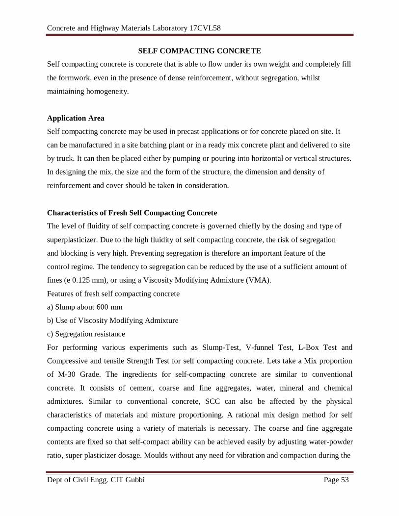
SELF COMPACTING CONCRETE
Self compacting concrete is concrete that is able to flow under its own weight and completely fill
the formwork, even in the presence of dense reinforcement, without segregation, whilst
maintaining homogeneity.
Application Area
Self compacting concrete may be used in precast applications or for concrete placed on site. It
can be manufactured in a site batching plant or in a ready mix concrete plant and delivered to site
by truck. It can then be placed either by pumping or pouring into horizontal or vertical structures.
In designing the mix, the size and the form of the structure, the dimension and density of
reinforcement and cover should be taken in consideration.
Characteristics of Fresh Self Compacting Concrete
The level of fluidity of self compacting concrete is governed chiefly by the dosing and type of
superplasticizer. Due to the high fluidity of self compacting concrete, the risk of segregation
and blocking is very high. Preventing segregation is therefore an important feature of the
control regime. The tendency to segregation can be reduced by the use of a sufficient amount of
fines (e 0.125 mm), or using a Viscosity Modifying Admixture (VMA).
Features of fresh self compacting concrete
a) Slump about 600 mm
b) Use of Viscosity Modifying Admixture
c) Segregation resistance
For performing various experiments such as Slump-Test, V-funnel Test, L-Box Test and
Compressive and tensile Strength Test for self compacting concrete. Lets take a Mix proportion
of M-30 Grade. The ingredients for self-compacting concrete are similar to conventional
concrete. It consists of cement, coarse and fine aggregates, water, mineral and chemical
admixtures. Similar to conventional concrete, SCC can also be affected by the physical
characteristics of materials and mixture proportioning. A rational mix design method for self
compacting concrete using a variety of materials is necessary. The coarse and fine aggregate
contents are fixed so that self-compact ability can be achieved easily by adjusting water-powder
ratio, super plasticizer dosage. Moulds without any need for vibration and compaction during the
Concrete and Highway Materials Laboratory 17CVL58
Dept of Civil Engg. CIT Gubbi Page 54
pouring process. It can be used in pre-cast applications or for concrete placed on site. SCC
results in durable concrete structures, and saves labour and consolidation noise.
Basic principles for production of self-compacting concrete
Schematic Composition of SCC
At the stage before solidification, self-compacting concrete is required to have three qualities:
high-flowabilityresistance against segregation and possibility, i.e, ability that is necessary to pass
the space between reinforcing bars. Other additional properties, such as, washout resistance and
finishability, may be significant and specified for individual projects/applications. Therefore, it is
important to test whether the concrete is selfcompactable or not and also to evaluate
deformability or viscosity for estimating proper mix proportioning if the concrete does not have
sufficient selfcompactability. The existing procedures for self-compacting characteristics are
those, which measure height differences at different points under free flow and also resistance
against blocking.
Concrete and Highway Materials Laboratory 17CVL58
Dept of Civil Engg. CIT Gubbi Page 55
Slump flow test
Percent of
Flow 0 – 20 % 20 – 60 % 60 – 100 %
100 – 120 % 120 – 150 %
Consistency Dry Stiff Plastic Wet Sloppy
Concrete and Highway Materials Laboratory 17CVL58
Dept of Civil Engg. CIT Gubbi Page 56
Exp No: Date:
Flow Test
Aim:
The flow table test or flow test is a method to determine the consistence of fresh concrete.
Equipment:
Flow table with a grip and a hinge, 70 cm x 70 cm.
Abrams cone, open at the top and at the bottom - 30 cm high, 17 cm top diameter, 25 cm
base diameter
Water bucket and broom for wetting the flow table.
Tamping rod, 60 cm height
Scale for measurement
Principle:
This test is giving us the ability of concrete to flow under the gravitational force when poured
and compacted within the cone and suddenly lifted up
The basic equipment used is the same as for theconventional Slump test. The test method differs from the conventional one in the way that the concrete sampleplaced into the mould has no
reinforcement rod and when theslump cone is removed the sample collapses. The diameter of
the spread of the sample is measured, ie, a horizontal distanceis measured as against the vertical
slump measured in theconventional test. While measuring the diameter of the spread,
the time that the sample takes to reach a diameter of 500 mm(T50) is also sometimes measured.
The Slump Flow test cangive an indication about the filling ability of SCC and anexperienced
operator can also detect an extreme susceptibilityof the mix to segregation.
Procedure:
1. The flow table is wetted.
2. The cone is placed on the flow table and filled with fresh concrete in two layers, each
layer 25 times tamp with tamping rod.
3. The cone is lifted, allowing the concrete to flow.
4. The flow table is then lifted up several centimeters and then dropped, causing the
concrete flow a little bit further.
5. After this the diameter of the concrete is measured in a 6 different direction and take the average.
Concrete and Highway Materials Laboratory 17CVL58
Dept of Civil Engg. CIT Gubbi Page 57
Fig. V-funnel
Concrete and Highway Materials Laboratory 17CVL58
Dept of Civil Engg. CIT Gubbi Page 58
Exp No: Date:
V-Funnel Test
Aim: This test gives account of the filling capacity (flowability).
Equipment:
1. V-funnel, as shown in Figure 7, made of steel, with a flat, horizontal top and placed on
vertical supports, and with a momentary releasable, watertight opening gate
2. Stopwatch with the accuracy of 0.1 secondfor recording the flow time
3. Straightedge for leveling the concrete
4. Buckets with a capacity of 12-14 litres for taking concrete sample
5. Moist sponge or towel for wetting the inner surface of the V-funnel
Principle:
The V-funnel test was developed in Japan and used by Ozawa, et al. The equipment consists of a
V-shaped funnel. The funnel is filled with concrete and the time taken by it to flow through the
apparatus measured. This test gives account of the filling capacity (flowability). The inverted
cone shape shows any possibility of the concrete to block is reflected in the result.
Though the test is designed to measure flow ability, the result is affected by concrete properties
other than flow. The inverted cone shape will cause any liability of the concrete to block to be
reflected in the result-if, for example there is too much coarse aggregate. High flow time can also
be associated with low deformability due to a high paste viscosity, and with high inter-particle
friction.
Procedure
1. Place the cleaned V-funnel vertically on a stable and flat ground, with the top opening
horizontally positioned
2. Wet the interior of the funnel with the moist sponge or towel and remove the surplus of
water, e.g. through the opening. The inner side of the funnel should be ‘just wet’.
3. Close the gate and place a bucket under it in order to retain the concrete to be passed
4. Fill the funnel completely with a representative sample of SCC without applying any
compaction or rodding
5. Remove any surplus of concrete from the top of the funnel using the straightedge.
Concrete and Highway Materials Laboratory 17CVL58
Dept of Civil Engg. CIT Gubbi Page 59
Concrete and Highway Materials Laboratory 17CVL58
Dept of Civil Engg. CIT Gubbi Page 60
Open the gate after a waiting period of (10 ± 2) seconds. Start the stopwatch at the same
moment the gate opens.
6. Look inside the funnel and stop the time at the moment when clear space is visible
through the opening of the funnel. The stopwatch reading is recorded as the V-funnel
flow time, noted as tV
7. Do not touch or move the V-funnel until it is empty.
Interpretation of result:
This test measures the ease of flow of concrete, shorter flow time indicates greater flow ability.
For SCC a flow time of 10 seconds is considered appropriate. The inverted cone shape restricts
the flow, and prolonged flow times may give some indication of the susceptibility of the mix to
blocking. After 5 minutes of settling, segregation of concrete will show a less continuous flow
with an increase in flow time.
Concrete and Highway Materials Laboratory 17CVL58
Dept of Civil Engg. CIT Gubbi Page 61
J-Ring Test Apparatus
Concrete and Highway Materials Laboratory 17CVL58
Dept of Civil Engg. CIT Gubbi Page 62
Exp No: Date:
J-Ring Test
Aim: The J-ring test aims at investigating both the filling ability and the passing
ability of SCC.
Apparatus:J-ring, Straight rod for aligning the reference line in the measurement,
with a length of about 400 mm and at least one flat side having the flexure less
than 1 mm.
Procedure
1. Place the cleaned base plate in a stable and level position
2. Fill the bucket with 6~7 litres of representative fresh SCC and let the sample stand still
for about 1 minute (± 10 seconds).
3. Under the 1 minute waiting period pre-wet the inner surface of the cone and the test
urface of the base plate using the moist sponge or towel, and place the cone in the centre
on the 200 mm circle of the base plate and put the weight ring on the top of the cone to
keep it in place. (If a heavy cone is used, or the cone is kept in position by hand no
weight ring is needed).
4. Place the J-ring on the base plate around the cone
5. Fill the cone with the sample from the bucket without any external compacting action
such as rodding or vibrating. The surplus concrete above the top of the cone should be
struck off, and any concrete remaining on the base plate should be removed
6. Check and make sure that the test surface is neither too wet nor too dry. No dry area on
the base plate is allowed and any surplus of the water should be removed – the moisture
state of the plate shall be ‘just wet’.
7. After a short rest (no more than 30 seconds for cleaning and checking the moist state of
the test surface), lift the cone perpendicular to the base plate in a single movement, in
such a manner that the concrete is allowed to flow out freely without obstruction from the
cone, and start the stopwatch the moment the cone loose the contact with the base plate
Concrete and Highway Materials Laboratory 17CVL58
Dept of Civil Engg. CIT Gubbi Page 63
Concrete and Highway Materials Laboratory 17CVL58
Dept of Civil Engg. CIT Gubbi Page 64
8. Stop the stopwatch when the front of the concrete first touches the circle of diameter 500
mm. The stopwatch reading is recorded as the T50J value. The test is completed when the
concrete flow has ceased.
9. lay the straight rod with the flat side on the top side of the J-ring and measure the relative
height differences between the lower edge of the straight rod and the concrete surface at
the central position (Δh0) and at the four positions outside the J-ring, two (Δhx1, Δhx2)
in the x-direction and the other two (Δhy1, Δhy2) in the y-direction (perpendicular to x)
10. Measure the largest diameter of the flow spread, dmax, and the one perpendicular to it,
dperp, using the ruler (reading to nearest 5 mm). Care should be taken to prevent the ruler
from bending
Expression Of Results
The J-ring flow spread SJ is the average of diameters dmax and dperp, SJ is expressed in mm to the
nearest 5 mm
Expression Of Results
The J-ring flow time T50J is the period between the moment the cone leaves the base plate and
SCC first touches the circle of diameter 500 mm. T50J is expressed in seconds to the nearest
1/10 seconds
The J-ring blocking step BJ is calculated using equation and expressed in mm to the nearest 1
mm.
Concrete and Highway Materials Laboratory 17CVL58
Dept of Civil Engg. CIT Gubbi Page 65
U-Box Test Apparatus
Concrete and Highway Materials Laboratory 17CVL58
Dept of Civil Engg. CIT Gubbi Page 66
Exp No: Date:
U box test
Aim: The test is used to measure the filing ability of self compacting concrete
Apparatus: U box of a stiff non absorbing material, Scoop.Trowel, Stopwatch
The test is used to measure the filing ability of self compacting concrete. The apparatus consists
of a vessel that is divided by a middle wall into two compartments; an opening with a sliding
gate is fitted between the two sections. Reinforcing bar with nominal diameter of 134 mm are
installed at the gate with centre to centre spacing of 50 mm. this create a clear spacing of 35 mm
between bars. The left hand section is filled with about 20 liter of concrete then the gate is lifted
and the concrete flows upwards into the other section. The height of the concrete in both sections
is measured.
Procedure:
1. About 20 liter of concrete is needed to perform the test, sampled normally.
2. Set the apparatus level on firm ground, ensure that the sliding gate can open freely and
then close it. Moisten the inside surface of the apparatus, remove any surplus water, fill
the vertical section of the apparatus with the concrete sample.
3. Leave it stand for 1 minute. Lift the sliding gate and allow the concrete to flow out into
the other compartment. After the concrete has come to rest, measure the height of the
concrete in the compartment that has been filled, in two places and calculate the mean
(H1).
4. Measure also the height in the other equipment (H2). Calculate H1-H2, the filling height.
The whole test has to be performed within 5 minutes.
Interpretation of the result:
If the concrete flows as freely as water, at rest it will be horizontal, so H1-H2=0. Therefore the
nearest this test value, the ‘filling height’, is to zero, the better the flow and passing ability of
the concrete.
Concrete and Highway Materials Laboratory 17CVL58
Dept of Civil Engg. CIT Gubbi Page 67
Concrete and Highway Materials Laboratory 17CVL58
Dept of Civil Engg. CIT Gubbi Page 68
Exp No: Date:
L-Box Test
Aim: The method aims at investigating the passing ability of SCC.
Apparatus
Two types of gates can be used, one with 3 smooth bars and one with 2 smooth bars. The
gaps are 41 and 59 mm, respectively
Suitable tool for ensuring that the box is level i.e. a spirit level
Suitable buckets for taking concrete sample
Principle
It measures the reached height of fresh SCC after passing through the specified
gaps of steel bars and flowing within a defined flow distance. With this reached
height, the passing or blocking behavior of SCC can be estimated.
Procedure
1. Place the L-box in a stable and level position
2. Fill the vertical part of the L-box, with the extra adapter mounted, with 12.7
liters of representative fresh SCC
3. Let the concrete rest in the vertical part for one minute (± 10 seconds). During
this time the concrete will display whether it is stable or not (segregation).
4. Lift the sliding gate and let the concrete flow out of the vertical part into the
horizontal part of the L-box.
5. When the concrete has stopped moving, measure the average distance, noted as
Δh, between the top edge of the box and the concrete that reached the end of the
box, at three positions, one at the centre and two at each side.
Expression of Results
The passing ratio PL or blocking ratio BL is calculated using equation and
expressed in dimensionless to the nearest 0.01
Concrete and Highway Materials Laboratory 17CVL58
Dept of Civil Engg. CIT Gubbi Page 69
Aggregate Crushing Test Apparatus
OBSERVATION
Sample I Sample II
Total weight of dry sample taken= W1
gm
Weight of portion passing 2.36 mm
sieve= W2gm
Aggregate crushing = (W2/W1)*100
Value (per cent)
Concrete and Highway Materials Laboratory 17CVL58
Dept of Civil Engg. CIT Gubbi Page 70
Exp No: Date:
AGGREGATE CRUSHING VALUE TEST
AIM: To determine the aggregate crushing value of coarse aggregates.
APPARATUS: The apparatus of the aggregate crushing value test as per IS: 2386 (Part IV) –
1963consists of:
1. A 15cm diameter open ended steel cylinder with plunger and base plate, of the general
form and dimensions as shown in Fig
2. A straight metal tamping rod of circular cross-section 16mm diameter and 45 to 60 cm
long, rounded at one end.
3. A balance of capacity 3k, readable and accurate up to 1 g.
4. IS Sieves of sizes 12.5,10 and 2.36 mm
5. A compression testing machine capable of applying load up to 40tonnes. At uniform rate
of 4tonnes. /minute
6. Cylindrical measure having internal dia. of 11.5cm. & height 18 cm. For measuring the
sample.
THEORY: The aggregate crushing value gives a relative measure of the resistance of an
aggregate to crushing under a gradually applied compressive load. Crushing value is a measure
of the strength of the aggregate. The aggregates should therefore have minimum crushing value.
PROCEDURE: The test sample: It consists of aggregates sized 12.5 mm - 10.0 mm(minimum
3kg). The aggregates should be dried by heating at 1000-1100 C for a period of 4 hours and
cooled.
1. Sieve the material through 12.5 mm and 10.0 mm IS sieve. The aggregates passing through 12.5
mm sieve and retained on 10.0 mm sieve comprises the test material.
2. The cylinder of the test shall be put in position on the base-plate and the test sample added in
thirds, each third being subjected to 25 strokes with the tamping rod.
3. The surface of the aggregate shall be carefully leveled.
Concrete and Highway Materials Laboratory 17CVL58
Dept of Civil Engg. CIT Gubbi Page 71
Concrete and Highway Materials Laboratory 17CVL58
Dept of Civil Engg. CIT Gubbi Page 72
4. The plunger is inserted so that it rests horizontally on this surface, care being taken to ensure that
the plunger does not jam in the cylinder
5. The apparatus, with the test sample and plunger in position, shall then be placed between the
plates of the testing machine.
6. The load is applied at a uniform rate as possible so that the total load is reached in 10 minutes.
The total load shall be 40 tones.
7. The load shall be released and the whole of the material is removed from the cylinder and sieved
on 2.36mm IS Sieve.
8. The fraction passing the sieve shall be weighed and recorded.
PRECAUTIONS
1. The plunger should be placed centrally & rest directly on the aggregates .Care should be
taken that it does not touch the walls of the cylinder so as to ensure that the entire load ids
transferred onto the aggregates.
2. In the operation of sieving the aggregates through 2.36mm sieve & weighing care should
be taken to avoid loss of fines. The sum of weights of fractions retained & passing the
sieve should not differ from the originals weights of the specimen by more than 1gm.
3. The tamping should be done properly by gently dropping the tamping rod and not by
hammering action Also the tamping should be uniform over the surface.
REPORTING OF RESULTS
The mean of the two results shall be reported to the nearest whole number as the ‘aggregate
crushing value’ of the size of the material tested.
RESULT
Meanaggregate Crushing test value =
Concrete and Highway Materials Laboratory 17CVL58
Dept of Civil Engg. CIT Gubbi Page 73
LOS ANGELES ABRASION TESTING MACHIN
OB SERVATIONS Sample I Sample II
Total weight of dry sample taken= W1
gm
Weight of portion passing 1.7 mm
sieve= W2gm
Aggregate abrasion value =
(W2/W1)*100 Value (per cent)
Concrete and Highway Materials Laboratory 17CVL58
Dept of Civil Engg. CIT Gubbi Page 74
Exp No: Date:
ABRASION TEST
AIM: To determine Los Angeles abrasion valueof coarse aggregates.
APPARATUS:The apparatus as per IS: 2386 (Part IV) – 1963 consists of:
a) Los Angeles Machine: It consists of a hollow steel cylinder, closed at both the ends with an
internal diameter of 700 mm and length 500 mm and capable of rotating about its horizontal axis.
A removable steel shaft projecting radially 88 mm into cylinder and extending full length (i.e.
500 mm) is mounted firmly on the interior of cylinder. The shelf is placed at a distance 1250 mm
minimum from the opening in the direction of rotation.
b) Abrasive charge: Cast iron or steel balls, approximately 48 mm in diameter and each weighing
between 390 to 445 g; 6 to 12 balls are required.
c) Sieve: The 1.70 mm IS sieve
d) Balance of capacity 5 kg or 10 kg
e) Drying oven
f) Miscellaneous like tray etc
THEORY: The abrasion value of the aggregates is determined in order to determine their
resistance against wearing. In this the aggregate sample is mixed with abrasive charge consisting
of six standard balls & rotated in closed inclined cylinders for specific number of revolutions.
The abrasion value is then expressed as the percentage of abraded material with reference to the
original weight of the test sample.
PROCEDURE: Test Sample: It consists of clean aggregates dried in oven at 1050- 1100C and
are coarser than 1.70 mm sieve size. The sample should conform to any of the grading shown in
table.
Concrete and Highway Materials Laboratory 17CVL58
Dept of Civil Engg. CIT Gubbi Page 75
Concrete and Highway Materials Laboratory 17CVL58
Dept of Civil Engg. CIT Gubbi Page 76
TABLE 1 GRADING OF TEST SAMPLE
Sieve size
(square hole)
Weight in g of Test Sample for Grade
Passing
mm
Retained
on mm
A B C D E F G
80 63 - - - - 2500* - -
63 50 - - - - 2500* - -
50 40 - - - - 5000* 5000* -
40 25 1250 - - - - 5000* 5000*
25 20 1250 - - - - - 5000*
20 12.5 1250 2500 - - - - -
12.5 10 1250 2500 - - - - -
10 6.3 - - 2500 - - - -
6.3 4.75 - - 2500 - - - -
4.75 2.36 - - 5000 - - -
*Tolerance of ±12 percent permitted.
1. Select the grading to be used in the test. It should be chosen such that it conforms to the
grading to be used in construction, to the maximum extent possible.
2. Take 5 kg of sample for grading A, B, C or D and 10 kg for grading E, F and G.
3. Choose the abrasive charge as per Table 2.
TABLE 2 SELECTION OF ABRASIVE CHARGES
Grading No. of Steel balls Weight of charge, g
A 12 5000 ± 25
B 11 4584 ± 25
C 8 3330 ± 25
D 6 2500 ± 25
E 12 5000 ± 25
F 12 5000 ± 25
Concrete and Highway Materials Laboratory 17CVL58
Dept of Civil Engg. CIT Gubbi Page 77
1. The test sample and the abrasive charge shall be placed in the Los Angles abrasion
testing machine.
2. The machine is rotated at a speed of 20 to 33 rev/min for grading A, B,C and D, the
machine shall be rotated for 500 revolutions; for grading E, F and G, it shall be rotated
for 1000 revolutions
3. The material is discharged from the machine after the completion of the test and is sieved
through 1.7 mm IS sieve.
4. The weight of the aggregate passing through 1.7mm sieve is taken and recorde
REPORTING OF RESULTS The difference between the original weight and the final weight
of the test sample shall beexpressed as a percentage of the original weight of the test sample.
This value is reported asthe percentage wear.
TABLE 3. MAXIMUM L A ABRASION VALUES OF AGGREGATES IN DIFFERENT
TYPES OF PAVEMENT LAYERS
Sl no.
Types of pavement layer Maximum Los
Angeles Abrasion
value (%) 1 Water bound macadam ,sub-base course 60
2 i) WBM base course with bituminous surfacing
ii) Bituminous macadam base course iii) Built-up spray grout base course