16
Screw-Type Flow Meter SVC

Screw-Type Flow Meter
SVC

Screw-Type Flow Meter SVC
1 Housing2 Measuring system (screw spindles)3 Bearing (roller contact bearing)
4 Sensing wheel and sensors5 Seal (O-ring)6 Connection
Screw-type flow meters belong to the group ofpositive displacement flow meters. Two measuringspindles (pos. 2) with a screw-shaped profile engagewith each other. They are low-friction mounted usingroller contact bearings (pos. 3) and enclosed by ahousing (pos. 1). The liquid flow causes the spindlesto rotate and passes through the device in an axialdirection. In so doing, self-contained part volumes areformed which are continuously filled and emptied.This principle of measurement causes no pressureand/or flow pulsations.
A sensing wheel attached to the measuring spindle(pos. 4) is scanned by two non-contact sensors.Using two sensors, a bidirectional flow with detectionof flow-direction is possible. The inflow and outflowoccurs almost without deflection.Consequently, the device exhibits a relatively lowdrop in pressure. Measuring this way does not requirethe flow to be calmed at the inlet and outlet.All moving parts are lubricated by the measurementmedium.
Description
KRACHT GmbH · Gewerbestr. 20 · 58791 Werdohl, Germany · fon +49(0)23 92/935-0 · fax +49(0)23 92/935 209 · mail [email protected] · web www.kracht.eu2
Construction
Product Characteristics
• Very low pressure drop• High-response measurement• Measurement with changing flow direction• pulsation free measurement principle• High working pressure• Very low noise emission• Measurement independent of viscositywithin the specified ranges
• High-precision measurement with outstandingreproducibility
• Temperature-independent output signals overa wide temperature range
• High degree of accuracy, even with low flow ratesat the bottom end of the measuring range
• High working reliability of the electronics• Easy to use terminal of the preamplifier• Working indication of the electronic• Sensor system and preamplifier in EMC-compatibledesign
• Explosion-proof version available (ATEX)
3 4 6 2 1 5

KRACHT GmbH · Gewerbestr. 20 · 58791 Werdohl, Germany · fon +49(0)23 92/935-0 · fax +49(0)23 92/935 209 · mail [email protected] · web www.kracht.eu 3
Screw-Type Flow Meter SVC
The accuracy figures quoted by KRACHT refer tothe impulse volume [cm3/Imp], that is to say thepercentage deviation applies to the current valuein each case.
The linearity error over the entire measuring rangeis ≤ ±0.1%.
From a viscosity of 20 mm2/s amounts the accuracy≤ ±0.2% about the whole measuring span of 1 : 150.
Accuracy checking forms part of quality inspectionin every case.
On request the result of the test will be documentedin the form of an accuracy characteristic curve; anexample relating to a SVC 10 A1 is given below.
The accuracy values quoted by Kracht are confirmedby the DKD (German Calibration Service).
Accuracy Characteristics
Accuracy 1.433
1.428
1.423
1.418
1.413
1.408
1.403
+ 0.2 %
-- 0.2 %
0 25 50 75 100 125 150
Volumeper
pulse
(cm
3 )
Flow rate l/min
Linearity 1.433
1.428
1.423
1.418
1.413
1.408
1.403
+ 0.1 %
-- 0.1 %
0 25 50 75 100 125 150
Volumeper
pulse
(cm
3 )
Flow rate l/min

KRACHT GmbH · Gewerbestr. 20 · 58791 Werdohl, Germany · fon +49(0)23 92/935-0 · fax +49(0)23 92/935 209 · mail [email protected] · web www.kracht.eu4
Screw-Type Flow Meter SVC
Working Characteristics
Permitted Temperature Ranges
Nominal Impulse Resolution Resolution Pulse Measuring Starting point Measuringsize volume (K-factor) (K-factor) rate chamber Mounting position range
4-fold * at Qnenn volume horizontal verticalcm3/ lmp lmp/ l lmp/ l Hz cm3/U l/min l /min l /min
10 1.418 705.2 2820.9 1175 26.94 0.05 0.02 1.0… 150
40 5.130 194.9 779.7 1300 123.1 0.10 0.02 4.0… 600
100 9.85 101.5 406.1 1692 354.6 0.15 0.03 10.0… 150010.0… 1000( -version)
250 18.25 54.8 219.2 2283 985.5 0.90 0.06 25.0… 3750
Note: The ATEX characteristics SVC 10 and SVC 40 correspond to the standard characteristics.* Resolution with 4-fold evaluation of both measuring canals
Materials
Housing and flanges EN-GJS-400-15 (GGG-40)
Measuring spindles Heat-treated steel
Roller contact bearing Heat-treated steel
O-ring NBR, FKM, EPDM, FEP(other sealing materials on request)
Characteristics
Mounting position optional
Flow direction optional
Connection type Pipe thread, SAE-flange, DIN-flange
Working pressure SVC 10, SVC 40 pmax = 250 barSVC 100 pmax = 140 barSVC 250 pmax = 40 bar
Max. pressure drop (short-time) ∆ pmax = 25 bar(permanent) ∆ pmax = 7 bar (at 50% of the nominal flow)SVC 100 ∆ pmax = 10 bar( -version)
Viscosity 1…1,000,000 mm2/s (depending on the flow)
Sound power level SVC 10 LWA = 46 dB (A)SVC 40 LWA = 52 dB (A)
(at 100% of the nominal flow)
Sealing Materials NBR FKM EPDM FEP
Ambient temperature --30 °C … 80 °C --15 °C … 80 °C --30 °C … 80 °C --30 °C … 80 °C
Media temperatures:
Standard version --30 °C … 100 °C --15 °C … 120 °C --30 °C … 120 °C --30 °C … 120 °C
High temperature version n. a. --15 °C … 150 °C n. a. --30 °C … 150 °C
-version --30 °C … 80 °C --15 °C … 80 °C --30 °C … 80 °C --30 °C … 80 °C

KRACHT GmbH · Gewerbestr. 20 · 58791 Werdohl, Germany · fon +49(0)23 92/935-0 · fax +49(0)23 92/935 209 · mail [email protected] · web www.kracht.eu 5
Screw-Type Flow Meter SVC
Ordering example
SVC 10 A 1 G1 F 1 S 1
ElectronicsS standardH high temperatureV without preamplifierX protection-design
Connection1 Hirschmann connector
Design code number(specified by Kracht)
SealF FKMN NBRE EPDMP FEP
Connection typeG1 Pipe threadF1 SAE-flange (SAE Code 61)D. DIN-flange (DIN EN 1092)
Product name
Nominal size10 Qnenn 100 l/min (Qmax = 150 l/min)40 Qnenn 400 l/min (Qmax = 600 l/min)100 Qnenn 1000 l/min (Qmax = 1500 l/min)250 Qnenn 2500 l/min (Qmax = 3750 l/min)
SeriesA standard
Spindle bearing1 Roller contact bearing2 Roller contact bearing with NBR-sealing
(only size 10)
Type Key

KRACHT GmbH · Gewerbestr. 20 · 58791 Werdohl, Germany · fon +49(0)23 92/935-0 · fax +49(0)23 92/935 209 · mail [email protected] · web www.kracht.eu6
Screw-Type Flow Meter SVC
Electrical Connection
Signal output channel 1
24 Volt (brown)
Channel 1 (green)
Channel 2 (yellow)
0 Volt (white)
Signal outputchannel 2
Signal Characteristics
Channel IA rising edge
B one pulse(corr. to flow rate of geom. tooth volume Vgz)
C falling edge
D ON phase
E OFF phase
F pulse duty factor 1 :1 ± 15 %
Channel IIG channel offset
H flow direction 1
K reversal of flow direction
J flow direction 2
Electrical Characteristics
Number ofmeasuring channels 2
Operating voltage Uop = 12 ... 30 VDCpolarized
Pulse amplitude UA ≥ 0.8 UB
Pulse shape withsymm. output signal square wave
pulse duty factor /channel1 :1 ± 15 %
Signal output PNP (NPN on request)
Pulse offset betweentwo channels 90° ± 30°
Power requirement Pbmax = 0.9 W
Output power/channel Pamax = 0.3 Wshort-circuit-proof
Degree of protection IP 65 DIN 40050

KRACHT GmbH · Gewerbestr. 20 · 58791 Werdohl, Germany · fon +49(0)23 92/935-0 · fax +49(0)23 92/935 209 · mail [email protected] · web www.kracht.eu 7
Screw-Type Flow Meter SVC
Safe area
K 130
II (2) G [EEx ia] IIC PTB 03 ATEX 2094 X II 2 GD EEx ia IICT4 PTB 03 ATEX 2249
Potentially explosive atmosphere
Channel 2
24 Volt7, 8 and 9 jumpered
shield
0 Volt
white
brown
yellowgreenPA
brown white
Channel 1
Technical Data of Switching Amplifier K-130/3-E-10
Power supplySupply voltage cl. 7 (L+), cl. 10 (L--) DC 24 Volt ± 20 %Ripple content white Wss < 10 %
Outputs (non-intrinsically safe)Characteristics cl. 9, 12, 8, 11Electronics outputs electrically isolated via optoelectronic couplerShort-circuit current approx. 25 mASignal level 1-signal 0.8 x supply voltage with RL > 2 k ohmSignal level 0-signal inhibited output, residual current < 10 uA
Ambience conditionsMinimum limiting temperature 248 K (-- 25 °C)Maximum limiting temperature 333 K (+ 60 °C)
MechanicsDimensions 107.5 x 92 x 22 mmConnection possibility can be snapped on a 35 mm mounting channel DIN 46277Weight approx. 150 g
Explosion-Proof Design (ATEX)
• All screw-type flow meters are available in explosion-proof design according to ATEX.
• The explosion-proof design consists of the screw-typeflow meter (intrinsically safe electrical apparatus) andthe switching amplifier K 130 (associated electricalapparatus). The type of protection „intrinsic safety“applies to this construction.
• The screw-type flow meter is installed in the potentiallyexplosive atmosphere.
• The mounting of the amplifier K 130 is carried outin the safe area.
Function
• Screw-type flow meter and switching amplifier areelectrically connected to each other. The switchingamplifier evaluates the sensor signals and convertsthem to square-wave signals.
• Without switching amplifier, the screw-type flow meter mustnot be operated in the potentially explosive atmosphere.
• Cable lengths of up to 400 m are possible betweenscrew-type flow meter and switching amplifier.
• LED’s for monitoring line breaks / short circuits,channel switching state and power supply are locatedon the switching amplifier.
Note: This graph is an example only. National laws for potentially explosive areas must be considered.
1011
12
78
9
45
6
12
3
green yellow
SVC

Screw-Type Flow Meter SVC
KRACHT GmbH · Gewerbestr. 20 · 58791 Werdohl, Germany · fon +49(0)23 92/935-0 · fax +49(0)23 92/935 209 · mail [email protected] · web www.kracht.eu8
Pressure Drop Parameter: Viscosity (mm2/s)
Flow rate Q in l/min
SVC 10 A1
Pressure
drop∆pin
bar
0 30 60 90 120 150
20
18
16
14
12
10
8
6
4
2
0
2000
1000
2001005010
2000
1000
500
200100
Flow rate Q in l/min
SVC 10 A1 (� extract)
Pressure
drop∆pin
bar
0 10 20 30 40 50
8
7
6
5
4
3
2
1
0
345010
34
Extractsee right
500
Flow rate Q in l/min
SVC 40 A1
Pressure
drop∆pin
bar
0 150 300 450 600
20
18
16
14
12
10
8
6
4
2
0
3000
2000
1000
2001003410
3000
1000
2000
500
2001003410
Flow rate Q in l/min
SVC 40 A1 (� extract)
Pressure
drop∆pin
bar
0 40 80 120 160 200
8
7
6
5
4
3
2
1
0
Extractsee right
500

KRACHT GmbH · Gewerbestr. 20 · 58791 Werdohl, Germany · fon +49(0)23 92/935-0 · fax +49(0)23 92/935 209 · mail [email protected] · web www.kracht.eu 9
Screw-Type Flow Meter SVC
Pressure Drop Parameter: Viscosity (mm2/s)
Flow rate Q in l/min
SVC 100 A1
Pressure
drop∆pin
bar
0 300 600 900 1200 1500
20
18
16
14
12
10
8
6
4
2
0
2000
1000
20010050
2000
1000
500
Flow rate Q in l/min
SVC 100 A1 (� extract)
Pressure
drop∆pin
bar
0 100 200 300 400 500
8
7
6
5
4
3
2
1
0
1308034
20010050
1308034
Extractsee right 500
Flow rate Q in l/min
SVC 250 A1
Pressure
drop∆pin
bar
0 500 1000 1500 2000 2500
10
9
8
7
6
5
4
3
2
1
0
3000
2000
1000
1308034
3000
1000
2000
500
Flow rate Q in l/min
SVC 250 A1 (� extract)
Pressure
drop∆pin
bar
0 250 500 750 1000 1250
7
6
5
4
3
2
1
0
Ausschnittsiehe rechts 500
10050 130
8034
10050
Screw-Type Flow Meter SVC
KRACHT GmbH · Gewerbestr. 20 · 58791 Werdohl, Germany · fon +49(0)23 92/935-0 · fax +49(0)23 92/935 209 · mail [email protected] · web www.kracht.eu10 KRACHT GmbH · Gewerbestr. 20 · 58791 Werdohl, Germany · fon +49(0)23 92/935-0 · fax +49(0)23 92/935 209 · mail [email protected] · web www.kracht.eu10
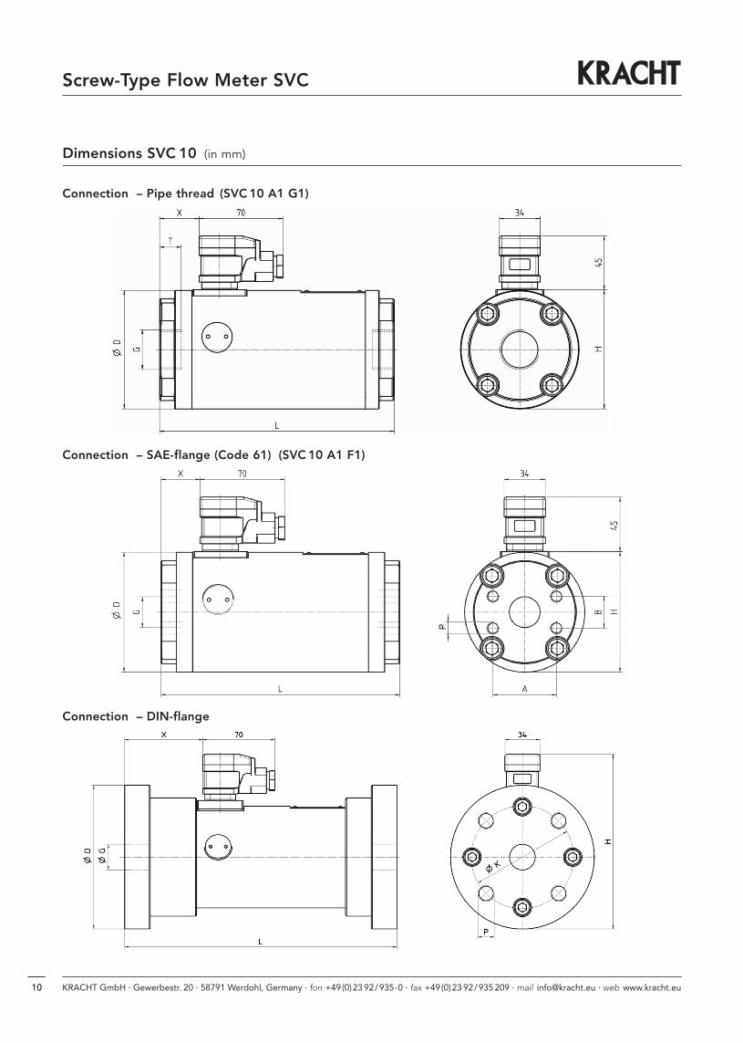
Dimensions SVC 10 (in mm)
Connection – Pipe thread (SVC 10 A1 G1)
Connection – SAE-flange (Code 61) (SVC 10 A1 F1)
Connection – DIN-flange

Screw-Type Flow Meter SVC
KRACHT GmbH · Gewerbestr. 20 · 58791 Werdohl, Germany · fon +49(0)23 92/935-0 · fax +49(0)23 92/935 209 · mail [email protected] · web www.kracht.eu 11KRACHT GmbH · Gewerbestr. 20 · 58791 Werdohl, Germany · fon +49(0)23 92/935-0 · fax +49(0)23 92/935 209 · mail [email protected] · web www.kracht.eu 11
Dimensions SVC 10 (in mm)
WeightNominal size A B D L K H G P T X kg
10 A1 G1 – – 99 196 – 101.5 * G 1 – 19 33 9.6
10 A1 F1 52.4 26.2 99 197 – 101.5 * SAE 1 M10 – 17 – 32 9.6deep
10 A1 D1 – – 140 265 100 167 * 32 M16 – 25 – 76 17.2deep
10 A1 D2 – – 140 265 100 167 * 25 M16 – 25 – 76 17.3deep
10 A1 D3 – – 150 275 105 172 * 25 M20 – 30 – 81 19.150deep
* plus 3 mm for electronic type “H“
Diameter Nominal Pressure dropDN (mm) PN (bar)
D1 32 40
D2 25 160
D3 25 250
Available DIN-flanges – type SVC 10

Screw-Type Flow Meter SVC
KRACHT GmbH · Gewerbestr. 20 · 58791 Werdohl, Germany · fon +49(0)23 92/935-0 · fax +49(0)23 92/935 209 · mail [email protected] · web www.kracht.eu12
Dimensions SVC 40 (in mm)
Connection – Pipe thread (SVC 40 A1 G1)
Connection – SAE-flange (Code 61) (SVC 40 A1 F1)
Connection – DIN-flange
KRACHT GmbH · Gewerbestr. 20 · 58791 Werdohl, Germany · fon +49(0)23 92/935-0 · fax +49(0)23 92/935 209 · mail [email protected] · web www.kracht.eu 13
Screw-Type Flow Meter SVC
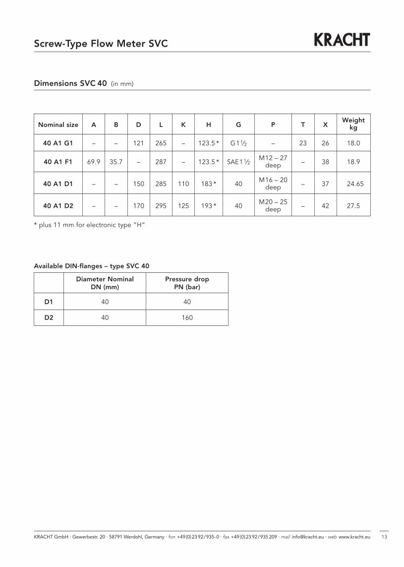
Dimensions SVC 40 (in mm)
Diameter Nominal Pressure dropDN (mm) PN (bar)
D1 40 40
D2 40 160
Available DIN-flanges – type SVC 40
WeightNominal size A B D L K H G P T X kg
40 A1 G1 – – 121 265 – 123.5 * G11⁄2 – 23 26 18.0
40 A1 F1 69.9 35.7 – 287 – 123.5 * SAE11⁄2M12 – 27 – 38 18.9deep
40 A1 D1 – – 150 285 110 183 * 40 M16 – 20 – 37 24.65deep
40 A1 D2 – – 170 295 125 193 * 40 M20 – 25 – 42 27.5deep
* plus 11 mm for electronic type “H“

Screw-Type Flow Meter SVC
KRACHT GmbH · Gewerbestr. 20 · 58791 Werdohl, Germany · fon +49(0)23 92/935-0 · fax +49(0)23 92/935 209 · mail [email protected] · web www.kracht.eu14
Dimensions SVC 100 (in mm)
Connection – Pipe thread (SVC 100 A1 G1)
Connection – SAE-flange (SVC 100 A1 F1)
Connection – DIN-flange

KRACHT GmbH · Gewerbestr. 20 · 58791 Werdohl, Germany · fon +49(0)23 92/935-0 · fax +49(0)23 92/935 209 · mail [email protected] · web www.kracht.eu 15
Screw-Type Flow Meter SVC
Dimensions SVC 100 (in mm)
WeightNominal size A B D L K H G P T X kg
100 A1 G1 – – 158 357 – 160 * G3 – 32 30 39.1
100 A1 F1 106.4 61.9 158 347 – 160 * SAE 3 M16 – 32 – 32 38.7deep
100 A1 D1 – – 200 365 160 226 * 80 M16 – 25 – 45 46.2deep
* plus 11 mm for electronic type “H“
Diameter Nominal Pressure dropDN (mm) PN (bar)
D1 80 40
Available DIN-flanges – type SVC 100
Dimensions SVC 250 (in mm)
WeightNominal size A B D L K H G P T X kg
250 A1 F1 130.2 77.8 200 440 – 203 * SAE 4 M16 – 30 – 37 76deep
* plus 11 mm for electronic type “H“
Connection – SAE-flange (SVC 250 A1 F1)

KRACHT GmbH · Gewerbestraße 20 · 58791 Werdohl, Germany · fon +49 (0) 23 92 / 935-0 · fax +49 (0) 23 92 / 935 209
mail [email protected] · web www.kracht.eu
SVC / GB /06.12
Transfer PumpsTransfer pumps for lubricating oilsupply equipment, low pressurefilling and feed systems, dosing andmixing systems.
Mobile HydraulicsSingle and multistage high pressuregear pumps, hydraulic motors andvalves for construction machinery,vehicle-mounted machines.
Flow MeasurementGear and turbine flow meters and electronicsfor volume and flow metering technology inhydraulics, processing and laquering technology.
Industrial Hydraulics /Test Bench ConstructionCetop directional control and proportionalvalves, hydraulic cylinders, pressure, quantityand stop valves for pipe and slab construction,hydraulic accessories for industrial hydraulics(mobile and stationary use).
Technology Test benches / Fluid Test benches.
Product Portfolio


