Abstract—Due to inertia-less feature of inverters, microgrids
with high penetration rate of inverter-interfaced distributed generators (DGs) usually suffer from power quality issues such as poor dynamic frequency stability. A promising solution of this issue is to apply virtual synchronous generator (VSG) control concept to inverter-interfaced DGs. In this paper, it is shown that compared to previous microgrid control scheme, e.g. conventional droop control, VSG control can improve microgrid frequency stability during loading transitions and fault events. This conclusion is demonstrated by theoretical time domain response of DG frequency obtained through small-signal analyses, and is verified by simulations performed in PSCAD/EMTDC.
Index Terms—Distributed power generation, droop control,
frequency stability, inverter, microgrid, virtual synchronous generator.
NOMENCLATURE 𝑆𝑆𝑏𝑏𝑏𝑏𝑏𝑏𝑏𝑏 Power rating 𝑃𝑃0, 𝑄𝑄0 Set value of active and reactive power 𝑃𝑃𝑖𝑖𝑖𝑖 Virtual shaft power 𝑃𝑃𝑜𝑜𝑜𝑜𝑜𝑜 , 𝑄𝑄𝑜𝑜𝑜𝑜𝑜𝑜 Output active and reactive power 𝑃𝑃𝑙𝑙𝑜𝑜𝑏𝑏𝑙𝑙 Load active power 𝑄𝑄𝑟𝑟𝑏𝑏𝑟𝑟 Reference value for reactive power control 𝜔𝜔0, 𝐸𝐸0 Nominal angular frequency and voltage 𝜔𝜔𝑚𝑚 Virtual rotor angular frequency 𝜔𝜔𝑔𝑔 Output voltage angular frequency 𝜃𝜃𝑚𝑚 Virtual rotor phase angle 𝐸𝐸 Virtual internal electromotive force 𝑉𝑉𝑜𝑜𝑜𝑜𝑜𝑜 Inverter output voltage 𝑉𝑉𝑏𝑏𝑜𝑜𝑏𝑏 Common ac bus voltage 𝐼𝐼𝑜𝑜𝑜𝑜𝑜𝑜 Inverter output current 𝑉𝑉𝑝𝑝𝑝𝑝𝑚𝑚, 𝜃𝜃𝑝𝑝𝑝𝑝𝑚𝑚 Voltage and phase of PWM reference 𝐽𝐽, 𝐷𝐷 Virtual inertia and virtual damping factor 𝑀𝑀∗ Inertia constant (= 𝐽𝐽𝜔𝜔0
2/𝑆𝑆𝑏𝑏𝑏𝑏𝑏𝑏𝑏𝑏) 𝑘𝑘𝑝𝑝, 𝑘𝑘𝑞𝑞 ω–P and V–Q droop coefficient 𝑅𝑅, 𝐿𝐿, Resistance and inductance 𝑋𝑋, 𝑍𝑍 Reactance and impedance 𝛿𝛿 Power angle 𝐾𝐾 Synchronizing power coefficient 𝑘𝑘𝑍𝑍, 𝑋𝑋/𝑅𝑅 proportional gain and 𝑋𝑋/𝑅𝑅 ratio of transi-
ent virtual stator impedance 𝑇𝑇𝑟𝑟𝑝𝑝, 𝑇𝑇𝑟𝑟𝑞𝑞 Time constant of 1st order filter for calcu-
lated active and reactive power 𝐾𝐾𝑝𝑝𝑞𝑞, 𝑇𝑇𝑖𝑖𝑞𝑞 Gain and time constant of reactive power
PI controller
J. Liu, Y. Miura, and T. Ise are with the Division of Electrical,
Electronic and Information Engineering, Graduate School of Engineering, Osaka University, Osaka, Japan (e-mail: [email protected], miura@eei. eng.osaka-u.ac.jp, [email protected]).
𝐾𝐾𝑝𝑝𝑏𝑏𝑏𝑏𝑝𝑝 , 𝑇𝑇𝑖𝑖𝑏𝑏𝑏𝑏𝑝𝑝 Gain and time constant of bus voltage and
frequency restoration PI controller
Subscripts/Superscripts: * Per unit value based on DG power rating i (i =1, 2) ith distributed generator f Inverter output LC filter line Distribution line ls Virtual stator α, β α-axis and β-axis component
I. INTRODUCTION Distributed power generation systems using renewable
energy resources such as solar panels and wind turbines have been developed in recent decades. As an inverter is usually installed at the output terminal, these systems are known as inverter-interfaced distributed generators (DGs).
To facilitate grid integration of DGs, the concept of “microgrid” is proposed to manage a cluster of DGs, distrib-uted energy storage systems (DESSs) and nearby loads as a single sub-system [1]. By applying microgrid configuration, the complexity of power system introduced by DGs can be significantly reduced. Meanwhile, as a microgrid can oper-ate in both islanded and grid-connected mode, high power supply reliability for internal loads can be obtained.
The control system of a microgrid is usually in a hierarchical structure, in which the primary control level embedded in DGs is responsible for basic operation and the secondary (and sometimes a tertiary) control level installed in a microgrid central controller (MGCC) is designed for optimal operation [2], [3]. Droop control is widely adopted in primary control level of microgrids, because it can provide automatic active and reactive power sharing between DGs in islanded mode and seamless transition between the two operation modes [4], [5].
However, unlike synchronous generators (SGs) with rotating mass, inverters have barely any inertia to support dynamic frequency stability. As a result, microgrids with high penetration rate of inverter-interfaced DGs may suffer from power quality issues such as large frequency deviation during loading transitions and fault events. To address this issue, virtual synchronous generator (VSG) control [6]–[10], or synchronverter [11], [12], inverter control methods to mimic dynamic characteristics of a SG by emulating the swing equation with virtual inertia and virtual damping factor, are proposed in the literature. It is also pointed out that inverters with VSG control can reduce rotor speed deviation of the conventional SGs moved by diesel or gas engine and operating in parallel with them in a VSC-HVDC transmission system [13] or a microgrid [14]; however, theoretical analysis is not provided. Detailed small-signal
Power Quality Improvement of Microgrids by Virtual Synchronous Generator Control
Jia Liu, Student Member, IEEE, Yushi Miura, Member, IEEE, and Toshifumi Ise, Member, IEEE
(a)
(b)
(c)
(d)
(e)
Fig. 2. Block diagrams of the adopted VSG control [16]. (a) Overall control scheme. (b) “Governor Model” block. (c) “Q Droop” block. (d) “Stator Impedance Adjuster” block. (e) “Vbus Estimator” block.
Fig. 1. The studied microgrid composed of two inverter-interfaced DGs.
analyses on the improved frequency stability introduced by VSG control are discussed in [15]; however, the case of parallel inverters, frequency restoration control in the secondary control level, and frequency behavior during a fault event are not included in this reference. An enhanced VSG control scheme for microgrid applications is presented in [16]; however, its improved dynamic frequency stability compared to conventional droop control is not thoroughly developed and thus should be further discussed.
In this paper, small-signal analyses are presented to study the dynamic response of microgrid frequency during loading transitions and fault events, for both VSG control proposed in [16] and an analogous droop control. The results are verified by simulations executed in PSCAD/EMTDC. It is demonstrated that thanks to the virtual inertia, VSG control results in lower frequency deviation during both loading transitions and fault events, thus improves the power quality of the microgrid.
II. SYSTEM CONFIGURATION AND CONTROL SCHEMES A microgrid composed of two parallel inverter-interfaced
DGs shown in Fig. 1 is studied in this paper. Two inverter-interfaced DGs are connected to the common ac bus in parallel, and passive loads composed of resistors and inductors are also connected to the bus through breakers. Control scheme embedded in the DGs using VSG concept is shown in Fig. 2 [16], and an analogous droop control method shown in Fig. 3 is also studied in this paper. As shown in Fig. 3, in order to focus on the dynamic frequency and to avoid influence from different voltage performance, only active power control part of VSG is replaced by conventional droop control, and reactive power control part is kept the same.
In the block “Swing Equation Function” of Fig. 2(a), swing equation (1) of a SG is emulated through iterative method, to provide virtual inertia and damping [7]–[10].
𝑃𝑃𝑖𝑖𝑖𝑖 − 𝑃𝑃𝑜𝑜𝑜𝑜𝑜𝑜 = 𝐽𝐽𝜔𝜔𝑚𝑚d𝜔𝜔𝑚𝑚d𝑜𝑜
+ 𝐷𝐷�𝜔𝜔𝑚𝑚 − 𝜔𝜔𝑔𝑔� (1)
In order to share steady-state active and reactive power, 𝜔𝜔 − 𝑃𝑃 and 𝑉𝑉 − 𝑄𝑄 droop control relations are inherited in the adopted VSG control, as shown in Figs. 2(b) and 2(c).
The “Stator Impedance Adjuster” block shown in Fig. 2(d) is to adjust the total output impedance of the DG by adding virtual stator impedance 𝑍𝑍𝑙𝑙𝑏𝑏 . The virtual stator impedance is composed of two parts, the constant virtual stator inductance 𝐿𝐿𝑙𝑙𝑏𝑏0 and the transient virtual stator imped-ance ∆𝑍𝑍𝑙𝑙𝑏𝑏 = ∆𝑅𝑅𝑙𝑙𝑏𝑏 + 𝜔𝜔0∆𝐿𝐿𝑙𝑙𝑏𝑏 . The constant virtual stator
inductance 𝐿𝐿𝑙𝑙𝑏𝑏0 is designed to share transient active power and to increase system damping, by adjusting the total output reactance of ith DG to 0.7 pu as shown in (2). 𝑋𝑋𝑖𝑖∗ = (𝐿𝐿𝑙𝑙𝑏𝑏0 𝑖𝑖 + 𝐿𝐿𝑟𝑟 𝑖𝑖 + 𝐿𝐿𝑙𝑙𝑖𝑖𝑖𝑖𝑏𝑏 𝑖𝑖)𝑆𝑆𝑏𝑏𝑏𝑏𝑏𝑏𝑏𝑏 𝑖𝑖𝜔𝜔0/𝐸𝐸02 = 0.7 pu (2)
The transient virtual stator impedance ∆𝑍𝑍𝑙𝑙𝑏𝑏 is proposed in [17] and developed in [16] to limit the DG overcurrent during a fault event. If the output current exceeds the predefined threshold value 𝐼𝐼𝑜𝑜ℎ𝑟𝑟𝑏𝑏𝑏𝑏ℎ (normally 1 pu), transient
(a)
(b)
Fig. 3. Block diagrams of an analogous droop control. (a) Overall control scheme. (b) “P Droop” block.
Fig. 4. Secondary control scheme in MGCC.
TABLE I. CONTROL PARAMETERS Parameter Value Parameter Value 𝑆𝑆𝑏𝑏𝑏𝑏𝑏𝑏𝑏𝑏1 10 kVA 𝐿𝐿𝑙𝑙𝑏𝑏0 1 6.39 mH 𝑆𝑆𝑏𝑏𝑏𝑏𝑏𝑏𝑏𝑏2 5 kVA 𝐿𝐿𝑙𝑙𝑏𝑏0 2 13.81 mH
𝐸𝐸0 = 𝑉𝑉𝑔𝑔𝑟𝑟𝑖𝑖𝑙𝑙 200 V 𝑘𝑘𝑍𝑍 𝑖𝑖 ∗ 1.79 pu
𝜔𝜔0 = 𝜔𝜔𝑔𝑔𝑟𝑟𝑖𝑖𝑙𝑙 376.99 rad/s 𝑋𝑋/𝑅𝑅𝑖𝑖 5 𝑀𝑀𝑖𝑖
∗ 8 s 𝑇𝑇𝑟𝑟𝑝𝑝 𝑖𝑖 7.96 × 10⁻³ s 𝐷𝐷𝑖𝑖∗ 17 pu 𝑇𝑇𝑟𝑟𝑞𝑞 𝑖𝑖 7.96 × 10⁻³ s
𝑃𝑃0 𝑖𝑖∗ (default) 1 pu 𝐾𝐾𝑝𝑝𝑞𝑞 𝑖𝑖
∗ 0.0125 pu 𝑄𝑄0 𝑖𝑖∗ (default) 0 pu 𝑇𝑇𝑖𝑖𝑞𝑞 𝑖𝑖 1.25 × 10⁻⁴ s 𝑘𝑘𝑝𝑝 𝑖𝑖∗ 20 pu 𝐾𝐾𝑝𝑝𝑏𝑏𝑏𝑏𝑝𝑝∗ 1 pu 𝑘𝑘𝑞𝑞 𝑖𝑖∗ 5 pu 𝑇𝑇𝑖𝑖𝑏𝑏𝑏𝑏𝑝𝑝 0.05 s
virtual stator impedance proportional to the amount of overcurrent will be applied to the DG in order to keep the overcurrent within acceptable range.
In the “Vbus Estimator” block shown in Fig. 2(e), ac bus voltage 𝑉𝑉𝑏𝑏𝑜𝑜𝑏𝑏 is calculated from DG output voltage and current, in order to generate an equivalent voltage reference for reactive power sharing.
In the droop control scheme shown in Fig. 3(a), the “Swing Equation Function” and “Governor Model” blocks of VSGs are replaced by a simple “P droop” block, in which conventional 𝑃𝑃 − 𝜔𝜔 droop relations is applied, as shown in Fig. 3(b). A first order low pass filter (LPF) with time constant 𝑇𝑇𝑟𝑟𝑝𝑝 is added in this block to filter the ripples in calculated output active power. It is pointed out in [13], [15] that this LPF can be also considered as virtual inertia; however, if this filter is designed traditionally, e.g. using 20 Hz cutoff frequency, the value of this virtual inertia is very small compared to that of VSG control.
As shown in Fig. 1, a MGCC is also included in this study. The secondary control scheme in MGCC shown in Fig. 4 is designed to restore the voltage and frequency of the
microgrid during islanded mode by adjusting the set value of active and reactive power of DGs. It is noteworthy that this secondary control should be inactivated during grid-connected mode and fault events, to avoid saturation of PI controller and the resulted abnormal control output.
The values of control parameters adopted in this paper are listed in Table I. It is noteworthy that per unit values of each DG are calculated according to respective power rating of each DG, in order to facilitate the design of the presented inverter-interfaced DGs.
III. ANALYSES OF DYNAMIC FREQUENCY STABILITY
A. Loading Transition Without Frequency Restoration First, to study the frequency dynamic during loading
transition, we begin with the case without frequency restoration control. By ignoring reactive power and line resistance in view of inductive output impedance and highly decoupled active and reactive power control, a state-space model for active power control part of the microgrid shown in Fig. 1 can be derived as shown in the following [16].
��̇�𝒙 = 𝑨𝑨𝒙𝒙 + 𝑩𝑩𝑩𝑩𝒚𝒚 = 𝑪𝑪𝒙𝒙 + 𝑫𝑫𝑩𝑩 , (3)
where 𝑩𝑩 = [∆𝑃𝑃𝑙𝑙𝑜𝑜𝑏𝑏𝑙𝑙 ∆𝑃𝑃0_1 ∆𝑃𝑃0_2]𝑇𝑇 (4) 𝒚𝒚 = [∆𝜔𝜔𝑚𝑚1 ∆𝜔𝜔𝑚𝑚2 ∆𝑃𝑃𝑜𝑜𝑜𝑜𝑜𝑜1 ∆𝑃𝑃𝑜𝑜𝑜𝑜𝑜𝑜2]𝑇𝑇 (5) and other matrices are omitted due to page limits, which can be referred to [16]. From this state-space model, transfer function of DG frequencies during a loading transition ∆𝜔𝜔𝑚𝑚 𝑖𝑖/∆𝑃𝑃𝑙𝑙𝑜𝑜𝑏𝑏𝑙𝑙 (i = 1, 2) can be obtained from the terms of 𝐺𝐺11(𝑠𝑠) and 𝐺𝐺21(𝑠𝑠) of transfer matrix 𝑮𝑮(𝑠𝑠) shown in (6). 𝑮𝑮(𝑠𝑠) = 𝑪𝑪(𝑠𝑠𝑰𝑰 − 𝑨𝑨)−1𝑩𝑩 + 𝑫𝑫 (6)
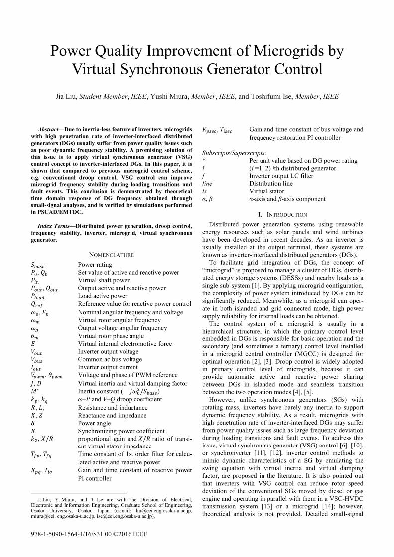
With these transfer functions, theoretical dynamic frequency performance of DG1 during a 15 kW (= 𝑆𝑆𝑏𝑏𝑏𝑏𝑏𝑏𝑏𝑏1 +𝑆𝑆𝑏𝑏𝑏𝑏𝑏𝑏𝑏𝑏2) step loading transition can be obtained as shown in Fig. 5. DG2 frequency is not shown because it is almost the same as that of DG1.
The transfer function of the case of using droop control can also be obtained from the same state-space model, by letting 𝐽𝐽𝑖𝑖 = 𝑘𝑘𝑝𝑝 𝑖𝑖𝑇𝑇𝑟𝑟𝑝𝑝 𝑖𝑖/𝜔𝜔0 and 𝐷𝐷𝑖𝑖 = 0 [15]. The resulted time response of DG1 frequency is also shown in Fig. 5.
As it is shown in Fig. 5, frequency change of DG1 is very fast in the case of droop control, but is slowed down in the case of VSG control, owing to the virtual inertia applied to the inverter. It implies that the frequency of VSG is less prone to change under a disturbance. This feature leads to better frequency stability as it is shown in later discussions.
B. Loading Transition With Frequency Restoration If the frequency restoration control in the MGCC is also
included, the state-space model shown in (3) should be modified. From Fig. 4, equation (7) can be easily obtained.
∆𝑃𝑃0_𝑖𝑖 = −𝐾𝐾𝑝𝑝𝑏𝑏𝑏𝑏𝑝𝑝 𝑖𝑖(1 + 1𝑇𝑇𝑖𝑖𝑖𝑖𝑖𝑖𝑖𝑖𝑏𝑏
)∆𝜔𝜔𝑏𝑏𝑜𝑜𝑏𝑏 (7)
To simplify the model, it is supposed that ∆𝜔𝜔𝑏𝑏𝑜𝑜𝑏𝑏 ≈ ∆𝜔𝜔𝑚𝑚1 in (7). This approximation will not influence the accuracy of the model because it is always true except the first several million seconds after a disturbance, whereas the settling time of frequency restoration control is usually of several seconds. Substituting (7) into (3), the state-space model should be modified as follow.
𝑨𝑨 =
⎣⎢⎢⎢⎢⎡−
𝐷𝐷1𝐾𝐾2𝐽𝐽1𝜔𝜔0(𝐾𝐾1+𝐾𝐾2)
− 𝑘𝑘𝑝𝑝1+𝐾𝐾𝑝𝑝𝑖𝑖𝑖𝑖𝑖𝑖1𝐽𝐽1𝜔𝜔0
𝐷𝐷1𝐾𝐾2𝐽𝐽1𝜔𝜔0(𝐾𝐾1+𝐾𝐾2)
− 𝐾𝐾1𝐽𝐽1𝜔𝜔0
− 𝐾𝐾𝑝𝑝𝑖𝑖𝑖𝑖𝑖𝑖1𝐽𝐽1𝜔𝜔0𝑇𝑇𝑖𝑖𝑖𝑖𝑖𝑖𝑖𝑖
𝐷𝐷2𝐾𝐾1𝐽𝐽2𝜔𝜔0(𝐾𝐾1+𝐾𝐾2)
− 𝐾𝐾𝑝𝑝𝑖𝑖𝑖𝑖𝑖𝑖2𝐽𝐽2𝜔𝜔0
− 𝐷𝐷2𝐾𝐾1𝐽𝐽2𝜔𝜔0(𝐾𝐾1+𝐾𝐾2)
− 𝑘𝑘𝑝𝑝2𝐽𝐽2𝜔𝜔0
𝐾𝐾1𝐽𝐽2𝜔𝜔0
− 𝐾𝐾𝑝𝑝𝑖𝑖𝑖𝑖𝑖𝑖2𝐽𝐽2𝜔𝜔0𝑇𝑇𝑖𝑖𝑖𝑖𝑖𝑖𝑖𝑖
𝐾𝐾2𝐾𝐾1+𝐾𝐾2
− 𝐾𝐾2𝐾𝐾1+𝐾𝐾2
0 01 0 0 0 ⎦
⎥⎥⎥⎥⎤
(9)
𝑩𝑩 =
⎣⎢⎢⎢⎢⎢⎡ − 𝐾𝐾1
𝐽𝐽1𝜔𝜔0(𝐾𝐾1+𝐾𝐾2)− 𝐷𝐷1𝐷𝐷2𝐾𝐾2
𝐽𝐽1𝐽𝐽2𝜔𝜔02(𝐾𝐾1+𝐾𝐾2)2
+ 𝐷𝐷12𝐾𝐾2
𝐽𝐽12𝜔𝜔0
2(𝐾𝐾1+𝐾𝐾2)2+ 𝐷𝐷1(𝑘𝑘𝑝𝑝1+𝐾𝐾𝑝𝑝𝑖𝑖𝑖𝑖𝑖𝑖1)
𝐽𝐽12𝜔𝜔0
2(𝐾𝐾1+𝐾𝐾2)1
𝐽𝐽1𝜔𝜔00
− 1𝐽𝐽2𝜔𝜔0
+ 𝐾𝐾1𝐽𝐽2𝜔𝜔0(𝐾𝐾1+𝐾𝐾2)
− 𝐷𝐷1𝐷𝐷2𝐾𝐾1𝐽𝐽1𝐽𝐽2𝜔𝜔0
2(𝐾𝐾1+𝐾𝐾2)2+ 𝐷𝐷2
2𝐾𝐾1𝐽𝐽22𝜔𝜔0
2(𝐾𝐾1+𝐾𝐾2)2+ 𝐷𝐷2𝑘𝑘𝑝𝑝2
𝐽𝐽22𝜔𝜔0
2(𝐾𝐾1+𝐾𝐾2)+ 𝐷𝐷1𝐾𝐾𝑝𝑝𝑖𝑖𝑖𝑖𝑖𝑖2
𝐽𝐽1𝐽𝐽2𝜔𝜔02(𝐾𝐾1+𝐾𝐾2)
0 1𝐽𝐽2𝜔𝜔0
− 𝐷𝐷1𝐾𝐾2𝐽𝐽1𝜔𝜔0(𝐾𝐾1+𝐾𝐾2)2
+ 𝐷𝐷2𝐾𝐾2𝐽𝐽2𝜔𝜔0(𝐾𝐾1+𝐾𝐾2)2
0 0
− 𝐷𝐷1𝐽𝐽1𝜔𝜔0(𝐾𝐾1+𝐾𝐾2)
0 0 ⎦⎥⎥⎥⎥⎥⎤
(10)
Fig. 5. Time responses of DG1 frequency during 15 kW loading transition while frequency restoration control is inactivated.
Fig. 6. Time responses of DG1 frequency during 15 kW loading transition while frequency restoration control is activated.
Fig. 7. Time responses of DG1 frequency during three-phase ground fault. (Input rectangular pulse duration: 0.1 s; amplitude: 15 kW)
𝒙𝒙 =
⎣⎢⎢⎢⎢⎡∆𝜔𝜔𝑚𝑚1 + 𝐷𝐷1
𝐽𝐽1𝜔𝜔0(𝐾𝐾1+𝐾𝐾2)∆𝑃𝑃𝑙𝑙𝑜𝑜𝑏𝑏𝑙𝑙
∆𝜔𝜔𝑚𝑚2 + 𝐷𝐷2𝐽𝐽2𝜔𝜔0(𝐾𝐾1+𝐾𝐾2)
∆𝑃𝑃𝑙𝑙𝑜𝑜𝑏𝑏𝑙𝑙
∆𝛿𝛿1 −1
𝐾𝐾1+𝐾𝐾2∆𝑃𝑃𝑙𝑙𝑜𝑜𝑏𝑏𝑙𝑙
∆𝜃𝜃𝑚𝑚1 ⎦⎥⎥⎥⎥⎤
(8)
𝑪𝑪 = �
1 0 0 00 1 0 00 0 𝐾𝐾1 00 0 −𝐾𝐾1 0
� (11)
𝑨𝑨 and 𝑩𝑩 are shown in the bottom of this page, and 𝑩𝑩, 𝒚𝒚, and 𝑫𝑫 are not changed.
With this modified state-space model, for the case where
frequency restoration control is applied, similar to Fig. 5, theoretical dynamic frequency performance of DG1 during a 15 kW step loading transition can be obtained as shown in Fig. 6. As it is shown in Fig. 6, owing to slower rate of change of frequency, VSG control results in smaller maximum frequency deviation during a loading transition before the frequency is restored by the secondary control from MGCC. Therefore, it can be concluded that the power quality of microgrid during a loading transition can be improved by VSG control.
C. Three-Phase Ground Fault To study the frequency behavior during a fault event, a
three-phase ground fault occurs in the ac bus of the microgrid is also investigated. As bus voltage is forced to 0 during the fault, the output power of DGs will drop down to a very low value. As a result, a three-phase ground fault can be modeled as a rectangular pulse in the input ∆𝑃𝑃𝑙𝑙𝑜𝑜𝑏𝑏𝑙𝑙. As mentioned previously, frequency and voltage restoration controls should be inactivated during a fault event to avoid PI controller saturation. Therefore, the transfer function derived from the state-space model without frequency restoration control shown in [16] is adopted in fault event study, and the results are shown in Fig. 7.
As it is shown in Fig. 7, when a 0.1 s, 15 kW rectangular pulse is imposed on ∆𝑃𝑃𝑙𝑙𝑜𝑜𝑏𝑏𝑙𝑙 to simulate a three-phase ground fault, the frequency of DG controlled by droop control soars up to around 1.05 pu, whereas the maximum frequency of DG controlled by VSG control is limited around 1.01 pu. Although the settling time in the case of droop control is shorter, it is a less important index than the maximum frequency deviation, as some sensible loads cannot work during a large frequency deviation of power supply. Again, VSG control outperforms conventional droop control owing to its virtual inertia which provides frequency support.
IV. SIMULATION RESULTS To verify the analyses presented in Section III, simula-
tions of the microgrid shown in Fig. 1 are performed in PSCAD/EMTDC, and the results are shown in Figs. 8–10.
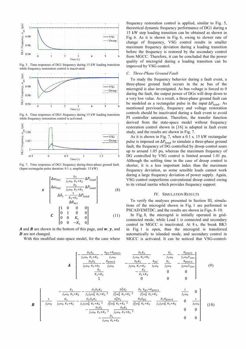
In Fig. 8, the microgrid is initially operated in grid-connected mode, while Load 1 is connected and secondary control in MGCC is inactivated. At 8 s, the break BK3 in Fig. 1 is open, thus the microgrid is transferred automatically to islanded mode, and secondary control in MGCC is activated. It can be noticed that VSG-control-
Fig. 8. Simulation results of islanding event and loading transition with VSG control in the left column and droop control in the right column. (a) Active power and frequency; (b) reactive power and voltage.
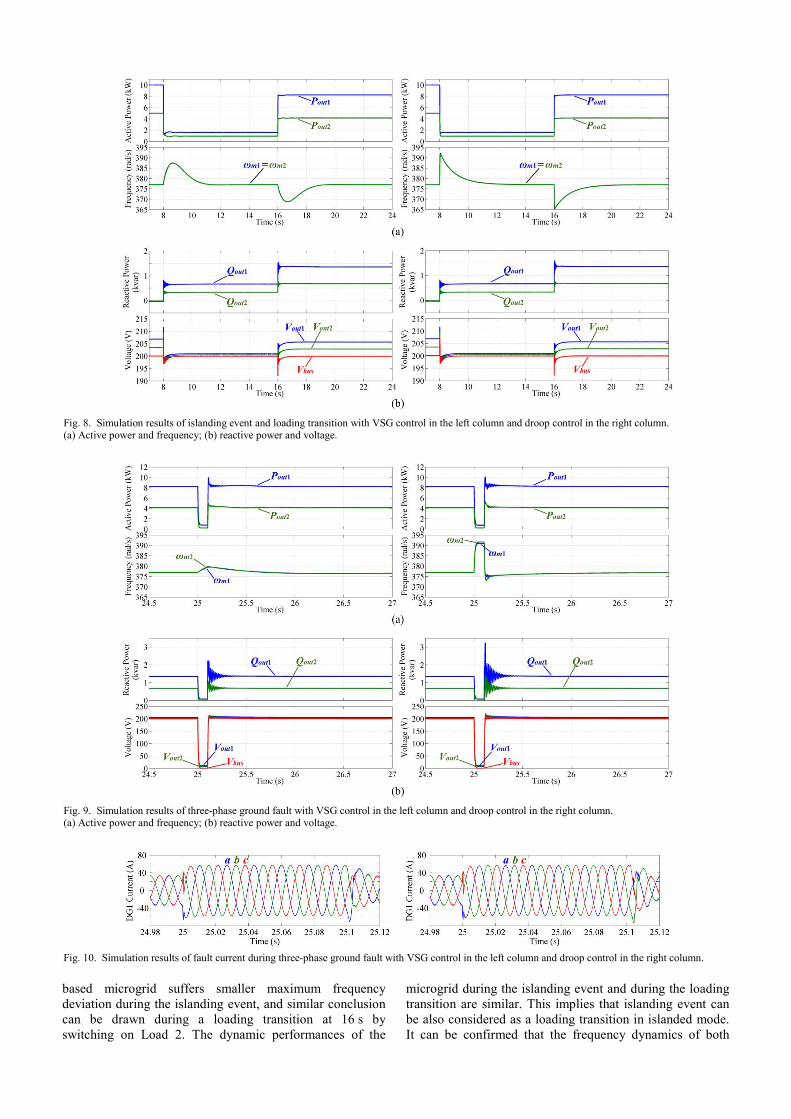
Fig. 9. Simulation results of three-phase ground fault with VSG control in the left column and droop control in the right column. (a) Active power and frequency; (b) reactive power and voltage.
Fig. 10. Simulation results of fault current during three-phase ground fault with VSG control in the left column and droop control in the right column.
based microgrid suffers smaller maximum frequency deviation during the islanding event, and similar conclusion can be drawn during a loading transition at 16 s by switching on Load 2. The dynamic performances of the
microgrid during the islanding event and during the loading transition are similar. This implies that islanding event can be also considered as a loading transition in islanded mode. It can be confirmed that the frequency dynamics of both
VSG control and droop control shown in Fig. 8 are similar to those in Fig. 6; therefore, the small-signal analyses on loading transition discussed in Section III is verified.
Fig. 9 is the following part of Fig. 8, in which the microgrid dynamics during a three-phase ground fault beginning at 25 s and lasting 0.1 s are depicted. It can be observed that the dynamic frequency during the fault is similar to Fig. 7, for both VSG control and droop control. This verifies the small-signal analyses and proves that VSG control leads to better dynamic frequency stability during a fault event. Some differences between Fig. 7 and Fig. 9 can be noticed after the clearance of fault, because the bus voltage does not settle down immediately as shown in Fig. 9(b), thus the ∆𝑃𝑃𝑙𝑙𝑜𝑜𝑏𝑏𝑙𝑙 is not a strict rectangular pulse after the clearance of fault. Besides, in the simulations, secondary control is inactivated after detection of fault event, and is reactivated right after the clearance of fault is detected, whereas Fig. 7 shows the time response without secondary control even after the clearance of fault.
The waveforms of the output current of DG1 during the three-phase ground fault are shown in Fig. 10. Considering the nominal peak current is about 41 A, the overcurrent is well controlled within 1.5 pu during the fault event by the transient virtual stator impedance method.
It is noteworthy that the performances of reactive and voltage are almost the same for both control methods as shown in Figs. 8 and 9, because the same reactive power control strategy is adopted in this study, and the active and reactive power controls are properly decoupled.
V. CONCLUSION In this paper, dynamic frequency of microgrid during
loading transitions and fault events was studied through a comparative approach, to demonstrate that the studied VSG control outperforms conventional droop control in view of better dynamic frequency stability. Both theoretical results from small-signal analyses and simulation results obtained in PSCAD/EMTDC were presented and compared, and the coherent results verified the improved frequency stability of microgrids introduced by the studied VSG control.
REFERENCES [1] R. H. Lasseter, “Microgrids,” in Proc. 2002 IEEE Power Eng. Soc.
Winter Meeting, pp. 305–308. [2] J. M. Guerrero, J. C. Vasquez, J. Matas, L. G. De Vicuña, and
M. Castilla, “Hierarchical control of droop-controlled DC and AC microgrids—A general approach towards standardization,” IEEE Trans. Ind. Electron., vol. 58, no. 1, pp. 158–172, Jan. 2011.
[3] A. Bidram and A. Davoudi, “Hierarchical structure of microgrids control system,” IEEE Trans. Smart Grid, vol. 3, no. 4, pp. 1963–1976, Dec. 2012.
[4] H. Nikkhajoei and R. H. Lasseter, “Distributed generation interface to the CERTS microgrid,” IEEE Trans. Power Del., vol. 24, no. 3, pp. 1598–1608, Jul. 2009.
[5] J. Rocabert, A. Luna, F. Blaabjerg, and P. Rodríguez, “Control of power converters in AC microgrids,” IEEE Trans. Power Electron., vol. 27, no. 11, pp. 4734–4749, Nov. 2012.
[6] J. Driesen and K. Visscher “Virtual synchronous generators,” in Proc. IEEE Power Energy Soc. Gen. Meeting—Convers. Del. Elect. Energy 21st Century, 2008, pp. 1–3.
[7] K. Sakimoto, Y. Miura, and T. Ise, “Stabilization of a power system including inverter type distributed generators by the virtual synchro-nous generator,” Electrical Engineering in Japan, vol. 187, no. 3, pp. 7–17, May 2014 [IEEJ Trans. Power and Energy, vol. 132, no. 4, pp. 341–349, Apr. 2012].
[8] T. Shintai, Y. Miura, and T. Ise, “Reactive power control for load sharing with virtual synchronous generator control,” in Proc. 7th Int. Power Electron. Motion Control Conf., 2012, pp. 846–853.
[9] T. Shintai, Y. Miura, and T. Ise, “Oscillation damping of a distributed generator using a virtual synchronous generator,” IEEE Trans. Power Del., vol. 29, no. 2, pp. 668–676, Apr. 2014.
[10] J. Alipoor, Y. Miura, and T. Ise, “Power system stabilization using virtual synchronous generator with alternating moment of inertia,” IEEE J. Emerg. Sel. Topics Power Electron., vol. 3, no. 2, pp. 451–458, Jun. 2015.
[11] Q.-C. Zhong and G. Weiss, “Synchronverters: inverters that mimic synchronous generators,” IEEE Trans. Ind. Electron., vol. 58, no. 4, pp. 1259–1267, Apr. 2011.
[12] Q.-C. Zhong, P.-L. Nguyen, Z. Ma, and W. Sheng, “Self-synchro-nized synchronverters: inverters without a dedicated synchronization unit,” IEEE Trans. Power Electron., vol. 29, no. 2, pp. 617–630, Feb. 2014.
[13] M. Guan, W. Pan, J. Zhang, Q. Hao, J. Cheng, and X. Zheng, “Synchronous generator emulation control strategy for voltage source converter (VSC) stations,” IEEE Trans. Power Syst., vol. 30, no. 6, pp. 3093–3101, Nov. 2015.
[14] J. Liu, Y. Miura, and T. Ise, “Parallel operation of a synchronous generator and a virtual synchronous generator under unbalanced loading condition in microgrids,” in Proc. 8th Int. Power Electron. Motion Control Conf., 2016.
[15] J. Liu, Y. Miura, and T. Ise, “Comparison of dynamic characteristics between virtual synchronous generator and droop control in inverter-based distributed generators,” IEEE Trans. Power Electron., vol. 31, no. 5, pp. 3600–3611, May 2016.
[16] J. Liu, Y. Miura, H. Bevrani, and T. Ise, “Enhanced virtual synchro-nous generator control for parallel inverters in microgrids,” IEEE Trans. Smart Grid, doi: 10.1109/TSG.2016.2521405.
[17] A. D. Paquette and D. M. Divan, “Virtual impedance current limiting for inverters in microgrids with synchronous generators,” IEEE Trans. Ind. Appl., vol. 51, no. 2, pp. 1630–1638, Mar./Apr. 2015.
Jia Liu (S’15) was born in Xuzhou, China, in 1986. He received the B.Eng. and M.Eng. degrees from Xi’an Jiaotong University, Xi’an, China, in 2008 and 2011, respectively, the Engineering degree from the University of Technology of Troyes, Troyes, France, in 2011, and the PhD.Eng. degree from Osaka University, Osaka, Japan, in 2016.
He was with Delta Electronics (Jiangsu), Ltd., Nanjing, China, from 2011 to 2012. Since 2016, he has been a Specially Appointed Assistant Pro-
fessor of the Division of Electrical, Electronic and Information Engineer-ing, Graduate School of Engineering, Osaka University. His research interests include power converter control, microgrids, modular multilevel converters, and motion control.
Yushi Miura (M’06) received the Doctoral degree in electrical and electronic engineering from the Tokyo Institute of Technology, Tokyo, Japan, in 1995.
From 1995 to 2004, he joined the Japan Atomic Energy Research Institute as a Research-er and developed power supplies and supercon-ducting coils for nuclear fusion reactors. Since 2004, he has been an Associate Professor of the Division of Electrical, Electronic and Information Engineering, Osaka University, Osaka, Japan.
His areas of research involve applications of power electronics for power systems.
Toshifumi Ise (M’86) was born in 1957. He received the B.Eng., M.Eng. and Doctor of Engi-neering degrees in electrical engineering from Osaka University, Osaka, Japan, in 1980, 1982 and 1986, respectively.
From 1986 to 1990, he was with the Nara National College of Technology, Nara, Japan. Since 1990, he has been with the Faculty of Engineering, Osaka University, where he is cur-rently a Professor of the Division of Electrical, Electronic and Information Engineering, Graduate
School of Engineering. His research interests are in the areas of power electronics and applied superconductivity for power systems including superconducting magnetic energy storage and future power systems including many distributed generations.