Educate – Enhance – Empower Version: 00/ feb 2018 THE GUIDELINES DESIGN IV / ENGINE ROOM LAYOUT Machinery and Electrical System Authors: Ir. Hari Prastowo, M.Sc Nurhadi Siswantoro, S.T., M.T. DEPARTMENT OF MARINE ENGINEERING FACULTY OF MARINE TECHNOLOGY - ITS 2018
Transcript
Educate – Enhance – Empower Version: 00/ feb 2018
THE GUIDELINES DESIGN IV / ENGINE ROOM LAYOUT Machinery and Electrical System
Authors: Ir. Hari Prastowo, M.Sc
Nurhadi Siswantoro, S.T., M.T.
DEPARTMENT OF MARINE ENGINEERING
FACULTY OF MARINE TECHNOLOGY - ITS
2018
Copyright: Dept. of Marine Engineering – ITS The guidelines for educational purposes only
Halaman ini sengaja dikosongkan
This page is intentionally left blank
Copyright: Dept. of Marine Engineering – ITS The guidelines for educational purposes only
SUBJECT : DESIGN IV / ENGINE ROOM LAYOUT
DOCUMENT TITTLE : THE GUIDELINES FOR DESIGN IV
/ ENGINE ROOM LAYOUT DOCUMENT NO : 01/D4-ERL/II/2018
DISCLAIMER
Manual desain ini hanya merupakan panduan untuk keperluan perkuliahan.
Penulis tidak merekomendasikan panduan ini dipakai untuk keperluan industri
dan komersial. Penulis tidak bertanggung-jawab bila terjadi kecelakaan yang
diakibatkan oleh penggunaan manual ini untuk aplikasi industri dan komersial.
This design manual is a guidelines for educational purposes only. The authors
do not recommend this guidelines for industrial and commercial purposes. The
author is not liable in the event of any accident resulting from the use of this
manual for industrial and commercial applications.
Copyright: Dept. of Marine Engineering – ITS The guidelines for educational purposes only
Halaman ini sengaja dikosongkan
This page is intentionally left blank
Copyright: Dept. of Marine Engineering – ITS The guidelines for educational purposes only
4. STANDAR DOKUMENTASI / STANDARD OF DOCUMENTATION................................... 3
LAMPIRAN A – Format laporan ...................................................................................... 3
LAMPIRAN B – Business Process ................................................................................ 23
LAMPIRAN C-1 - Design IV Machinery and Electrical System Form .......................... 27
LAMPIRAN C-2 – Engine Room Layout Form .............................................................. 41
Copyright: Dept. of Marine Engineering – ITS The guidelines for educational purposes only
Halaman ini sengaja dikosongkan
This page is intentionally left blank
DESIGN IV ENGINE ROOM LAYOUT
(Machinery and Electrical System) Doc. No 01/D4-ERL/II/2018
GUIDELINES
Rev. 00 Page 1 of 48
Date: February 2018
Copyright: Dept. of Marine Engineering – ITS The guidelines for educational purposes only
1. PENDAHULUAN
1. OVERVIEW
2. PROSEDUR
2. PROCEDURE
Prosedur dalam pengambilan mata kuliah Desain IV (ME141330) dan Ship Machinery Plants/Engine Room Layout (ME141603) secara garis besar dapat dilihat pada Lampiran B. 2.1 Mata Kuliah Pra-syarat Mahasiswa harus mengambil mata kuliah pra-syarat berikut sebelum mengambil Desain IV (ME141330) dan Ship Machinery Plants/Engine Room Layout (ME141603). Berikut adalah mata kuliah pra-syarat:
1. Design I 2. Design II 3. Design III 4. Ship Resistance & Propulsion 5. Marine Diesel & Propulsion
Systems 6. Marine Piping Systems 7. HVAC 8. Marine Electrical 9. Marine Safety
2.2 Pelaksanaan Pekerjaan Dalam pengerjaan tugas Desain IV/Engine Room Layout mahasiswa mengerjakan secara Tim.
The procedures for Design IV (ME141330) and Ship Machinery Plants / Engine Room Layout (ME141603), generally can be seen in Appendix B. 2.1 Pre-Requisite courses Students must take the following pre-requisite courses before taking Design IV (ME141330) and Ship Machinery Plants / Engine Room Layout (ME141603). Here are the pre-requisites:
1. Design I 2. Design II 3. Design III 4. Ship Resistance & Propulsion 5. Marine Diesel & Propulsion
Systems 6. Marine Piping Systems 7. HVAC 8. Marine Electrical 9. Marine Safety
2.2 Project Execution The student works on Partner/Team to finish Design IV / Engine Room Layout.
Panduan ini bertujuan sebagai pedoman mata kuliah Desain IV (ME141330) dan Ship Machinery Plants/Engine Room Layout (ME141603). Pedoman ini terdiri dari 3 bagian utama:
1. Prosedur 2. Laporan 3. Standar dokumentasi
The guidelines is intended as a guide for Design IV (ME141330) and Ship Machinery Plants/Engine Room Layout (ME141603). It consists of 3 main sections:
1. Procedures 2. Reports 3. Standard of documentation
DESIGN IV ENGINE ROOM LAYOUT
(Machinery and Electrical System) Doc. No 01/D4-ERL/II/2018
GUIDELINES
Rev. 00 Page 2 of 48
Date: February 2018
Copyright: Dept. of Marine Engineering – ITS The guidelines for educational purposes only
2.2.1 Tim Tim terdiri dari 2-3 mahasiswa
2.2.2 Dosen Pembimbing Dosen pembimbing terdiri dari Dosen Machinery dan Electrical
2.2.3 Deliverable Tim harus menyerahkan dokumen berupa: � Laporan Machinery System � Laporan Electrical System
catatan: (termasuk: gambar, lampiran yang mana telah disetujui oleh dosen pembimbing) pada saat UTS dan UAS
2.2.4 Monitoring Selama proses pengerjaan 16 minggu, ada 3 kali monitoring progress. � Progress I (Week 5) � Progress II (Week 10 + UTS) � Progress III (Week 16 + UAS)
Sudden death penalty: Jika tim tidak mampu menyelasaikan target pada setiap monitoring, maka tidak diperkenankan untuk melanjutkan ke tahap berikutnya. No Point of Return: Bila ada mahasisw yang melakukan “Drop” mata kuliah dan tidak menyelesaikan. Maka tidak akan diperkenankan untuk mengambil mata kuliah ini pada semester depannya.
2.2.1 Team The team consist of 2-3 students. 2.2.2 Supervisors The supervisor consist of machinery and electrical supervisor. 2.2.3 Deliverable The team must deliver documents of: � Report of Machinery System � Report of Electrical System
Note: (included: drawing, attachments which have been approved by the supervisor) at the Midterm and Final Examination 2.2.4 Monitoring There are 3 times monitoring progress for 16 weeks. � Progress I (Week 5) � Progress II (Week 10 + Mid
Exam) � Progress III (Week 16 + Final
Exam) Sudden death penalty: If the team is not able to complete the target on each monitoring, it is not allowed to proceed to the next stage. No Point of Return: Once decided to take this course must be finish. Those who quit from this course will not be allowed to take in the next consecutive semester.
DESIGN IV ENGINE ROOM LAYOUT
(Machinery and Electrical System) Doc. No 01/D4-ERL/II/2018
GUIDELINES
Rev. 00 Page 1 of 48
Date: February 2018
Copyright: Dept. of Marine Engineering – ITS The guidelines for educational purposes only
3. LAPORAN 3. REPORTStruktur laporan Desain IV / Engine Room Layout terdiri dari 3 bagian utama, yaitu:
a. Filosofi Desain b. Detail Perhitungan c. Lampiran (Spect, Drawing, dll)
3.1 Filosofi Desain Laporan machinery system terdiri dari 11 dokumen / filosofi desain, yaitu:
1. List codes of Equipment 2. Bilge System 3. Oily-Water Bilge System 4. Ballast System 5. Fire Main System 6. Fuel Oil System 7. Lubricating Oil System 8. Engine Cooling System 9. Compressed Air System 10. Domestic System 11. Engine Room Air Ventilation
System Laporan electrical terdiri dari 4 dokumen / filosofi desain:
1. Lightings and Electric Terminals 2. Communication and Navigation
Equipments 3. Emergency Source of Electricity
Power (ESEP) 4. Generator & Shore Connection
Note: Double Degree Program tidak ada electrical system Lihat Lampiran A untuk outline penulisan report.
The structure of Design IV / Engine Room Layout report, consists of 3 main parts, i.e.: a. Design Philosophy b. Detail of Calculation c. Attachment (Spect, Drawing,
etc)
3.1 Design Philosophy The report of machinery system consist of 11 documnets / design philosophy, i.e.:
1. List codes of Equipment 2. Bilge System 3. Oily-Water Bilge System 4. Ballast System 5. Fire Main System 6. Fuel Oil System 7. Lubricating Oil System 8. Engine Cooling System 9. Compressed Air System 10. Domestic System 11. Engine Room Air Ventilation
System
The electrical report consists of 4 documents / design philosophy:
1. Lightings and Electric Terminals
2. Communication and Navigation Equipments
3. Emergency Source of Electricity Power (ESEP)
4. Generator & Shore Connection
Note: Double Degree Program is not required for electrical system
See Appendix A for writing report outline.
DESIGN IV ENGINE ROOM LAYOUT
(Machinery and Electrical System) Doc. No 01/D4-ERL/II/2018
GUIDELINES
Rev. 00 Page 2 of 48
Date: February 2018
Copyright: Dept. of Marine Engineering – ITS The guidelines for educational purposes only
3.2 Detail Perhitungan Detail perhitungan merupakan pendukung dari isi filosofi desain. Detail perhitungan ditulis dalam format spreadsheet (Ms. Excel). Detail Perhitungan tambahan dapat ditambahkan apabila diperlukan. Detail perhitungan terdiri dari (minimal):
a. daftar code / referensi yang digunakan
b. algoritma perhitungan c. input parameter desain (given
parameter) d. output parameter desain e. detail perhitungan
Format detail perhitungan dapat dilihat Lampiran A 3.3 Lampiran
3.3.1 Spesifikasi Parameter spesifikasi merujuk pada lampiran (akan disediakan) 3.3.2 Gambar Gambar yang akan dikumpulkan adalah: � gambar schematic piping and
instrument (PID) diagram dan bukan process flow diagram (PFD)
� gambar Engine Room Layout, mencerminkan letak dan posisi peralatan sebenarnya di kamar mesin.
� gambar 3D, 2 gambar diantara 11 machinery system (masing-masing 1 gambar saat UTS dan UAS yang ditentukan oleh dosen pembimbing)
3.2 Detail of Calcuation Detail of calculation supports the content of the design philosophy. The calculation details are written in format spreadsheet (Ms. Excel). Additional calculations may be added when considered necessary. Detail of calculation consist of (at least):
a. list of code / reference b. calculation algorithm c. input of parameter design
(given parameter) d. output of parameters design e. detail of calculation
See Appendix A for format of calculation detail.
3.3 Attachment
3.3.1 Specification Minimum parameters to be stated in the spec is referring to the attachment (will be provided) 3.3.2 Drawing The drawing to be submitted are:
� schematic piping and instrument (PID) diagram drawing, not process flow diagram (PFD)
� Engine Room Layout drawings, reflecting the location and position of the actual equipment in the engine room
� 3D drawing, 2 drawings among 11 machinery systems (each drawing at Midterm Exam and Final Exam)
DESIGN IV ENGINE ROOM LAYOUT
(Machinery and Electrical System) Doc. No 01/D4-ERL/II/2018
GUIDELINES
Rev. 00 Page 3 of 48
Date: February 2018
Copyright: Dept. of Marine Engineering – ITS The guidelines for educational purposes only
Simbol yang digunakan pada gambar harus konsisten untuk semua gambar. Disarankan untuk merefer pada standar tertentu (JIS, DIN, ISO dll.) Format gambar data dilihat pada lampiran A 3.3.3 Lain-lain Lampiran tambahan dicantumkan bila ada yang diperlukan untuk mendukung detail perhitungan.
The symbols used in the drawing must be consistent for all keyplans. It is recommended to refer to certain standards (JIS, DIN, ISO etc.)
See Appendix A for format of drawing.
3.3.3 Others Other attachments are provided if support detail of calculations.
4. STANDAR DOKUMENTASI
4. STANDARD OF DOCUMENTATION
4.1 Format Penulisan Laporan a. Ukuran kertas adalah B5,
dengan berat minimal 70 gr. b. Left margin 2,5 cm; top margin
2 cm; right margin 1 cm; bottom margin 2 cm.
c. Font standar yang digunakan adalah Franklin Gothic Book. Font lain dapat digunakan untuk formula atau lambang lain yang spesifik.
d. Besar Font: i. Judul BAB menggunakan
huruf kapital dengan ukuran font 14 pt.
ii. Judul Seksi dari tiap tiap bab menggunakan ukuran font 12 pt.
iii. Judul sub seksi dari tiap tiap bab menggunakan ukuran font 11 pt.
iv. Isi dari bab menggunakan font ukuran 10 pt.
4.1 Format of Writting a. The paper size is B5, weighing
at least 70 grams. b. Left margin 2,5 cm; top margin
2 cm; right margin 1 cm; bottom margin 2 cm.
c. The standard font is the Franklin Gothic Book. Other fonts can be used for formulas or other specific symbols.
d. The size of font: i. Title CHAPTER uses
capital letters with 14 pt font size.
ii. The section title of each chapter uses a 12 pt font size.
iii. The sub-section title of each chapter uses the 11 pt font size.
iv. The contents of the chapter use a 11 pt size font.
DESIGN IV ENGINE ROOM LAYOUT
(Machinery and Electrical System) Doc. No 01/D4-ERL/II/2018
GUIDELINES
Rev. 00 Page 2 of 48
Date: February 2018
Copyright: Dept. of Marine Engineering – ITS The guidelines for educational purposes only
e. Spasi i. Spasi yang digunakan
untuk penulisan laporan adalah 1 (satu) spasi.
4.2 Format Gambar Kerja a. Ukuran kertas gambar adalah
A2 (420 mm x 594 mm) b. garis tepi gambar adalah 20
mm dari tepi kertas c. skala gambar disesuaikan
dengan ukuran kertas d. kepala gambar berukuran 120
mm x 60 mm
4.3 Soft Copy Semua pekerjaan harus diserahkan ke koordinator dalam bentuk soft copy sebelum ujian dimulai. Semua pekerjaan disimpan dalam CD yang terdiri dari :
a. Seluruh pekerjaan yang disimpan dalam satu file dalam format PDF, yang terdiri dari: i. Filosofi desain ii. Detail Perhitungan iii. Gambar Desain Sistem
b. Seluruh laporan dan gambar
kerja dalam format asli: i. Filosofi desain dalam bentuk
word ii. Detail Perhitungan dalam
format excel, spesifikasi peralatan dalam file html, pdf atau format lain
iii. Gambar Desain Sistem dalam bentuk autocad.
e. Spacing i. The spacing for report
writing is 1 (one) spacing.
4.2 Format of Keyplan a. The size of the drawing paper
is A2 (420 mm x 594 mm) b. the border of the drawing is 20
mm from the edge of the paper c. scale of drawing adjusted to
paper size d. Head of drawing is 120 mm x
60 mm
4.3 Soft Copy All documents must be submitted to the coordinator in soft copy before the examination. All documents is stored on a CD consisting of:
a. All work stored in one file in PDF format, which consists of:
i. Design philosophy ii. Detail of calculation iii. Drawing for all systems
b. All documents and drawings in
native format: i. Design philosophy in word
form ii. Detail of calculation in
excel format, equipment specifications in html, pdf or other format.
iii. All of drawings in autocad format.
DESIGN IV ENGINE ROOM LAYOUT
(Machinery and Electrical System) Doc. No 01/D4-ERL/II/2018
GUIDELINES
Rev. 00 Page 3 of 48
Date: February 2018
Copyright: Dept. of Marine Engineering – ITS The guidelines for educational purposes only
LAMPIRAN A – Format laporan
APPENDIX A – The Format of Report
DESIGN IV ENGINE ROOM LAYOUT
(Machinery and Electrical System) Doc. No 01/D4-ERL/II/2018
GUIDELINES
Rev. 00 Page 4 of 48
Date: February 2018
Copyright: Dept. of Marine Engineering – ITS The guidelines for educational purposes only
Halaman ini sengaja dikosongkan
This page is intentionally left blank
DESIGN IV ENGINE ROOM LAYOUT
(Machinery and Electrical System) Doc. No 01/D4-ERL/II/2018
GUIDELINES
Rev. 00 Page 5 of 48
Date: February 2018
Copyright: Dept. of Marine Engineering – ITS The guidelines for educational purposes only
Contoh Format Front Cover / Template of Front Cover
For Report of Machinery System
DESIGN IV – ME 141330 (20pt) MARINE MACHINERY AND ELECTRICAL SYSTEM (18pt) EVEN SEMESTER 2017/2018 (18pt) BOOK 1 REPORT MACHINERY (Franklin Gothic Book 16pt)
Prepared by Team No. WWXX-YYZZ (Franklin Gothic Book 12pt) (Name of Student 1) – (NRP) (Franklin Gothic Book 11pt) (Name of Student 1) – (NRP) (Franklin Gothic Book 11pt)
Supervisor machinery: (Franklin Gothic Book 12pt)
(Name of Supervisor) (Franklin Gothic Book 11pt) (NIP. _____________) (Franklin Gothic Book 11pt)
DEPARTMENT OF MARINE ENGINEERING (16pt) FACULTY OF MARINE TECHNOLOGY (12pt) INSTITUT TEKNOLOGI SEPULUH NOPEMBER (ITS) (12pt) SURABAYA (12pt) 20XX (12pt)
1st 2nd 3rd
4th
Background of cover based on number of attempt
DESIGN IV ENGINE ROOM LAYOUT
(Machinery and Electrical System) Doc. No 01/D4-ERL/II/2018
GUIDELINES
Rev. 00 Page 6 of 48
Date: February 2018
Copyright: Dept. of Marine Engineering – ITS The guidelines for educational purposes only
Contoh Format Front Cover / Template of Front Cover
For Report of Electrical System
DESIGN IV – ME 141330 (20pt) MARINE MACHINERY AND ELECTRICAL SYSTEM (18pt) EVEN SEMESTER 2017/2018 (18pt) BOOK 2 REPORT ELECTRICAL (Franklin Gothic Book 16pt)
Prepared by Team No. WWXX-YYZZ (Franklin Gothic Book 12pt) (Name of Student 1) – (NRP) (Franklin Gothic Book 11pt) (Name of Student 1) – (NRP) (Franklin Gothic Book 11pt)
Supervisor machinery: (Franklin Gothic Book 12pt)
(Name of Supervisor) (Franklin Gothic Book 11pt) (NIP. _____________) (Franklin Gothic Book 11pt)
DEPARTMENT OF MARINE ENGINEERING (16pt) FACULTY OF MARINE TECHNOLOGY (12pt) INSTITUT TEKNOLOGI SEPULUH NOPEMBER (ITS) (12pt) SURABAYA (12pt) 20XX (12pt)
1st 2nd 3rd
4th
Background of cover based on number of attempt
DESIGN IV ENGINE ROOM LAYOUT
(Machinery and Electrical System) Doc. No 01/D4-ERL/II/2018
GUIDELINES
Rev. 00 Page 7 of 48
Date: February 2018
Copyright: Dept. of Marine Engineering – ITS The guidelines for educational purposes only
Contoh Format Front Cover / Template of Front Cover
For Report of Engine Room Layput (Double Degree Program)
ENGINE ROOM LAYOUT –ME141603 (20pt) EVEN SEMESTER 2017/2018 (18pt)
Prepared by Team No. YYZZ (Franklin Gothic Book 12pt) (Name of Student 1) – (NRP) (Franklin Gothic Book 11pt) (Name of Student 1) – (NRP) (Franklin Gothic Book 11pt)
Supervisor: (Franklin Gothic Book 12pt)
(Name of Supervisor) (Franklin Gothic Book 11pt) (NIP. _____________) (Franklin Gothic Book 11pt)
DOUBLE DEGREE PROGRAM (16pt) DEPARTMENT OF MARINE ENGINEERING (16pt) INSTITUT TEKNOLOGI SEPULUH NOPEMBER (ITS) (12pt) HOCHSHULE WISMAR (12pt) 20XX (12pt)
1st 2nd 3rd
4th
Background of cover based on number of attempt
DESIGN IV ENGINE ROOM LAYOUT
(Machinery and Electrical System) Doc. No 01/D4-ERL/II/2018
GUIDELINES
Rev. 00 Page 8 of 48
Date: February 2018
Copyright: Dept. of Marine Engineering – ITS The guidelines for educational purposes only
Contoh Format Cover (Batas Setiap Dokumen) / Template of Cover In each Document
For Report of Machinery System
DESIGN IV MACHINERY SYSTEM
DEPARTMENT OF MARINE ENGINEERING
font : FRANKLIN GOTHIC BOOK 14pt)
JUDUL DOKUMEN / TITTLE OF
DOCUMENT (e.g. BILGE SYSTEM)
(font : FRANKLIN GOTHIC BOOK 24pt
BOLD) Doc.No. 01 - 42 VV WWXX – LE
(font : FRANKLIN GOTHIC BOOK 12 pt)
(Font FRANKLIN GOTHIC BOOK 10 pt)
Rev. Date Remark
Prepared by Checked by Approved by
Name of
Student 1
Name of
Student 2 Name of Supervisor
(signed) (signed) (signed)
DESIGN IV ENGINE ROOM LAYOUT
(Machinery and Electrical System) Doc. No 01/D4-ERL/II/2018
GUIDELINES
Rev. 00 Page 9 of 48
Date: February 2018
Copyright: Dept. of Marine Engineering – ITS The guidelines for educational purposes only
Contoh Format Cover (Batas Setiap Dokumen) / Template of Cover In each Document
For Report of Machinery Electrical
DESIGN IV ELECTRICAL SYSTEM
DEPARTMENT OF MARINE ENGINEERING
font : FRANKLIN GOTHIC BOOK 14pt)
JUDUL DOKUMEN / TITTLE OF
DOCUMENT (e.g. LIGHTINGS AND
ELECTRIC TERMINALS)
(font : FRANKLIN GOTHIC BOOK 24pt
BOLD) Doc.No. 01 - 42 VV YYZZ - EL
(font : FRANKLIN GOTHIC BOOK 12 pt)
(Font FRANKLIN GOTHIC BOOK 10 pt)
Rev. Date Remark
Prepared by Checked by Approved by
Name of
Student 1
Name of
Student 2 Name of Supervisor
(signed) (signed) (signed)
DESIGN IV ENGINE ROOM LAYOUT
(Machinery and Electrical System) Doc. No 01/D4-ERL/II/2018
GUIDELINES
Rev. 00 Page 10 of 48
Date: February 2018
Copyright: Dept. of Marine Engineering – ITS The guidelines for educational purposes only
Contoh Format Cover (Batas Setiap Dokumen) / Template of Cover In each Document
For Report of Engine Room Layout (only for Double Degree Program)
ENGINE ROOM LAYOUT
DOUBLE DEGREE ON MARINE ENGINEERING
ITS – HOCHSCHULE WISMAR
font : FRANKLIN GOTHIC BOOK 14pt)
JUDUL DOKUMEN / TITTLE OF
DOCUMENT (e.g. BILGE SYSTEM)
(font : FRANKLIN GOTHIC BOOK 24pt
BOLD) Doc.No. 01 - 42 XX YYZZ – BG
(font : FRANKLIN GOTHIC BOOK 12 pt)
(Font FRANKLIN GOTHIC BOOK 10 pt)
Rev. Date Remark
Prepared by Checked by Approved by
Name of
Student 1
Name of
Student 2
Name of
Supervisor
(signed) (signed) (signed)
DESIGN IV ENGINE ROOM LAYOUT
(Machinery and Electrical System) Doc. No 01/D4-ERL/II/2018
GUIDELINES
Rev. 00 Page 11 of 48
Date: February 2018
Copyright: Dept. of Marine Engineering – ITS The guidelines for educational purposes only
Contoh Penulisan Laporan / Template of Writing Report
NAME OF SYSTEM (14pt Franklin Gothic Book)
Doc. No. 01 - 42 XX YYZZ – LE
Rev. No. BB
Page CC of DD
I. INTRODUCTION (12pt Franklin Gothic Book) Bilge system in ships or vessels helps to remove excess water from engine
room, machinery spaces, cargo spaces, and other rooms below the main deck
of the ship. Water accumulated trough leakage, condensation, and other
means will go to the bilge well. Special case that water in the engine room or
machinery spaces are mixed with oil. So, to suct the excess water, will be
needed pumps to transfer the oily water from bilge well to the holding tank.
Then, another small pump will be needed to transfer the oily water rom the
holding tank through the OWS (Oil Water Separator). (11 Franklin Gothic
Book)
II. OBJECTIVES The things that we must understand about Bilge System are:
1. Understand the bilge system inside the ship.
2. Calculate the diameter of the main bilge and the branch bilge in ship.
3. Determining the capacity and head of bilge pump according BKI Rules Vol.
III Section 11.
4. Choosing the pipe and pump which match to the calculation above.
5. Drawing the design of bilge system
III. REFERENCES 1. BKI Volume III for Machinery Installations 2016 Edition
2. Pompa dan Kompresor Ir. Sularso dan Haruo Tahara, M MSE
3. BKI Volume II for Hull 2014 Edition
IV. LIST OF ABBREVATIONS HLs : Head loss mayor suction side (m)
Hld : Head loss discharge side (m)
Mls : Head loss minor at suction side (m)
Mld : Head loss minor at discharge side (m)
dH : Calculated inside diameter of main bilge pipe (mm)
B : Moulded breadth of the ship (m)
DESIGN IV ENGINE ROOM LAYOUT
(Machinery and Electrical System) Doc. No 01/D4-ERL/II/2018
GUIDELINES
Rev. 00 Page 12 of 48
Date: February 2018
Copyright: Dept. of Marine Engineering – ITS The guidelines for educational purposes only
NAME OF SYSTEM (14pt Franklin Gothic Book)
Doc. No. 01 - 42 XX YYZZ – LE
Rev. No. BB
Page CC of DD
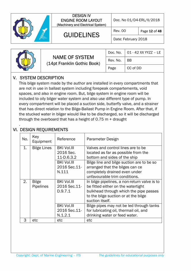
V. SYSTEM DESCRIPTION This bilge system made by the author are installed in every compartments that
are not in use in ballast system including forepeak compartements, void
spaces, and also in engine room. But, bilge system in engine room will be
included to oily bilger water system and also use different type of pump. In
every compartment will be placed a suction side, butterfly valve, and a strainer
that has direct relation to the Bilge-Ballast Pump in Engine Room. After that, if
the stucked water in bilger wiould like to be discharged, so it will be discharged
through the overboard that has a height of 0.75 m + draught
.
VI. DESIGN REQUIREMENTS
No. Key Equipment
Reference Parameter Design
1.
Bilge Lines BKI Vol.III 2016 Sec. 11-D.6.3.2
Valves and control lines are to be located as far as possible from the bottom and sides of the ship
BKI Vol.III 2016 Sec.11-N.111
Bilge line and bilge suction are to be so arranged that the bilges can ce completely drained even under unfavourable trim conditions.
2. Bilge Pipelines
BKI Vol.III 2016 Sec.11-D.9.7.1
In bilge pipelines, a non-return valve is to be fitted either on the watertight bulkhead through which the pipe passes to the bilge suction or at the bilge suction itself.
BKI Vol.III 2016 Sec.11-N.1.2.1
Bilge pipes may not be led through tanks for lubricating oil, thermail oil, and drinking water or feed water.
3 etc etc etc
DESIGN IV ENGINE ROOM LAYOUT
(Machinery and Electrical System) Doc. No 01/D4-ERL/II/2018
GUIDELINES
Rev. 00 Page 13 of 48
Date: February 2018
Copyright: Dept. of Marine Engineering – ITS The guidelines for educational purposes only
NAME OF SYSTEM (14pt Franklin Gothic Book)
Doc. No. 01 - 42 XX YYZZ – LE
Rev. No. BB
Page CC of DD
VII. SUMMARY OF CALCULATION 1. Calculated of Main Bilge Pipe
Main Pipe Diameter (dH) = mm
= inches
Spesification of pipe according to
Nominal Size = inches
= mm
Inside Diameter (dH) = inches
= mm
Outside Diameter (da) = inches
= mm
Schedule Number =
=
Thickness (s) = inches
= mm
2. Calculated of Branch Bilge Pipe Branch Pipe Diameter (dH) = mm
= inches
Spesification of pipe according to
Nominal Size = inches
= mm
Inside Diameter (dH) = inches
= mm
Outside Diameter (da) = inches
= mm
Schedule Number =
=
Thickness (s) = inches
= mm
DESIGN IV ENGINE ROOM LAYOUT
(Machinery and Electrical System) Doc. No 01/D4-ERL/II/2018
GUIDELINES
Rev. 00 Page 14 of 48
Date: February 2018
Copyright: Dept. of Marine Engineering – ITS The guidelines for educational purposes only
NAME OF SYSTEM (14pt Franklin Gothic Book)
Doc. No. 01 - 42 XX YYZZ – LE
Rev. No. BB
Page CC of DD
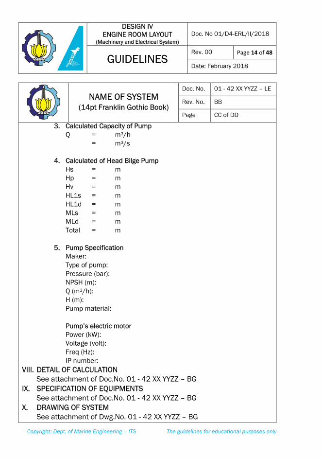
3. Calculated Capacity of Pump
Q = m3/h
= m3/s
4. Calculated of Head Bilge Pump
Hs = m
Hp = m
Hv = m
HL1s = m
HL1d = m
MLs = m
MLd = m
Total = m
5. Pump Specification
Maker:
Type of pump:
Pressure (bar):
NPSH (m):
Q (m3/h):
H (m):
Pump material:
Pump’s electric motor
Power (kW):
Voltage (volt):
Freq (Hz):
IP number:
VIII. DETAIL OF CALCULATION
See attachment of Doc.No. 01 - 42 XX YYZZ – BG
IX. SPECIFICATION OF EQUIPMENTS
See attachment of Doc.No. 01 - 42 XX YYZZ – BG
X. DRAWING OF SYSTEM
See attachment of Dwg.No. 01 - 42 XX YYZZ – BG
DESIGN IV ENGINE ROOM LAYOUT
(Machinery and Electrical System) Doc. No 01/D4-ERL/II/2018
GUIDELINES
Rev. 00 Page 15 of 48
Date: February 2018
Copyright: Dept. of Marine Engineering – ITS The guidelines for educational purposes only
DESIGN IV ELECTRICAL SYSTEM
DEPARTMENT OF MARINE ENGINEERING
font : FRANKLIN GOTHIC BOOK 14pt)
JUDUL LAMPIRAN / TITTLE OF
ATTACHMENT
(e.g. ATTACHMENT OF BILGE SYSTEM)
(font : FRANKLIN GOTHIC BOOK 24pt
BOLD) Attachment of Doc.No. 01 - 42 XX YYZZ – BG
(font : FRANKLIN GOTHIC BOOK 12 pt)
DESIGN IV ENGINE ROOM LAYOUT
(Machinery and Electrical System) Doc. No 01/D4-ERL/II/2018
GUIDELINES
Rev. 00 Page 16 of 48
Date: February 2018
Copyright: Dept. of Marine Engineering – ITS The guidelines for educational purposes only
ENGINE ROOM LAYOUT
DOUBLE DEGREE ON MARINE ENGINEERING
ITS – HOCHSCHULE WISMAR
font : FRANKLIN GOTHIC BOOK 14pt)
JUDUL LAMPIRAN / TITTLE OF
ATTACHMENT
(e.g. ATTACHMENT OF BILGE SYSTEM)
(font : FRANKLIN GOTHIC BOOK 24pt
BOLD) Attachment of Doc.No. 01 - 42 XX YYZZ – BG
(font : FRANKLIN GOTHIC BOOK 12 pt)
DESIGN IV ENGINE ROOM LAYOUT
(Machinery and Electrical System) Doc. No 01/D4-ERL/II/2018
GUIDELINES
Rev. 00 Page 17 of 48
Date: February 2018
Copyright: Dept. of Marine Engineering – ITS The guidelines for educational purposes only
DETAIL CALCULATION OF
BILGE SYSTEM (14pt Franklin Gothic Book)
Doc. No. 01 - 42 XX YYZZ – LE
Rev. No. BB
Page CC of DD
I. CALCULATION (12pt Franklin Gothic Book)
Content of calculation (11 Franklin Gothic Book)
Spreadsheet modeling for detail of calcuation in Ms.excel.
DESIGN IV ENGINE ROOM LAYOUT
(Machinery and Electrical System) Doc. No 01/D4-ERL/II/2018
GUIDELINES
Rev. 00 Page 18 of 48
Date: February 2018
Copyright: Dept. of Marine Engineering – ITS The guidelines for educational purposes only
SPECIFICATION OF BILGE
SYSTEM (14pt Franklin Gothic Book)
Dwg. No. 02 - 42 VV WWXX - BG
Rev. No. BB
Page CC of DD
Registrasi Equipment
Equipment ID : 100.01
Name : FO Transfer Pump
Specification
Maker : Allweiller
Type : SNS 660 ER 40
Capacity : 31.2 m3/h
Pressure : 3 bar
Catalog of specification
attached
DESIGN IV ENGINE ROOM LAYOUT
(Machinery and Electrical System) Doc. No 01/D4-ERL/II/2018
GUIDELINES
Rev. 00 Page 19 of 48
Date: February 2018
Copyright: Dept. of Marine Engineering – ITS The guidelines for educational purposes only
KEYPLAN OF BILGE
SYSTEM (14pt Franklin Gothic Book)
Dwg. No. 02 - 42 VV WWXX - BG
Rev. No. BB
Page CC of DD
DESIGN IV ENGINE ROOM LAYOUT
(Machinery and Electrical System) Doc. No 01/D4-ERL/II/2018
GUIDELINES
Rev. 00 Page 20 of 48
Date: February 2018
Copyright: Dept. of Marine Engineering – ITS The guidelines for educational purposes only
3D DRAWING OF BILGE
SYSTEM (14pt Franklin Gothic Book)
Dwg. No. 02 - 42 VV WWXX – 3D
Rev. No. BB
Page CC of DD
DESIGN IV ENGINE ROOM LAYOUT
(Machinery and Electrical System) Doc. No 01/D4-ERL/II/2018
GUIDELINES
Rev. 00 Page 21 of 48
Date: February 2018
Copyright: Dept. of Marine Engineering – ITS The guidelines for educational purposes only
Contoh Standar Gambar / Template of Drawing Standar
DESIGN IV ENGINE ROOM LAYOUT
(Machinery and Electrical System) Doc. No 01/D4-ERL/II/2018
GUIDELINES
Rev. 00 Page 22 of 48
Date: February 2018
Copyright: Dept. of Marine Engineering – ITS The guidelines for educational purposes only
Contoh Standar Kepala Gambar / Template of Head of Drawing Standar
*(dimension in millimeters)
Signed
Signed
Signed
Signed
Signed
Signed
DESIGN IV ENGINE ROOM LAYOUT
(Machinery and Electrical System) Doc. No 01/D4-ERL/II/2018
GUIDELINES
Rev. 00 Page 23 of 48
Date: February 2018
Copyright: Dept. of Marine Engineering – ITS The guidelines for educational purposes only
LAMPIRAN B – Business Process
APPENDIX B - Business Process
DESIGN IV ENGINE ROOM LAYOUT
(Machinery and Electrical System) Doc. No 01/D4-ERL/II/2018
GUIDELINES
Rev. 00 Page 24 of 48
Date: February 2018
Copyright: Dept. of Marine Engineering – ITS The guidelines for educational purposes only
Halaman ini sengaja dikosongkan
This page is intentionally left blank
DESIGN IV ENGINE ROOM LAYOUT
(Machinery and Electrical System) Doc. No 01/D4-ERL/II/2018
GUIDELINES
Rev. 00 Page 25 of 48
Date: February 2018
Copyright: Dept. of Marine Engineering – ITS The guidelines for educational purposes only
DEPARTMENT OF MARINE ENGINEERINGBUSINESS PROCESS OF DESIGN IV / ENGINE ROOM LAYOUT
COORDINATORSTUDENT SUPERVISOR EXAMINER
Rev
isio
n F
eb
20
18
START
Pre-Requisite courses
1. Design I
2. Design II
3. Design III
4. Ship Resistance & Propu ls ion
5. Marine Diesel & Propu ls ion Systems
6. Marine Piping Systems
7. HVAC
8. Marine Electrical
9. Marine Safety
Registration via FRS
1. Verify registration
2. List of Students
3. Coordinator grouping the
student by List of machinery
supervisor
SUPERVISION & APPROVAL
1. Form 01 (Document of assignment)
2. Form 03 (Completion)
3. Form 04 (Supervision Logbook)
WEEK-3
Verify Form 01
(Document of assignment)
OK?DROP NA
SUPERVISION & APPROVAL
1. Form 03 (Completion)
2. Form 04 (Supervision Logbook)
WEEK-10
VERIFY PROGRESS II
1. Form 03 (Completion)
2. Form 04 (Supervision
Logbook)
OK?DROP N
Y
BY
Supervisor of Machinery
1. Supervisor machinery
determines Team Partner
2. The team consist of 2-3
students.
Team Partner register(via Google Form)
1. List of Team Partner
2. Coordinator grouping the
Team Partner by List of
electrical supervisor
Supervisor of Electrical
Given List of team Partner
by CoordinatorUpload (via ME-Care)
1. Form 00 (Integrity P act)
2. Form 01 (Document of assignment)
3. Form 02 (Statement of lateness)
4. Form 03 (Completion)
5. Form 04 (Supervision Logbook)
6. Form 05 (Supervisor’s assessment)
Download Form 00 - 05
WEEK-5
VERIFY PROGRESS I
1. Form 03 (Completion)
2. Form 04 (Supervision
Logbook)
OK?
A
Y N
Page 1 of 2
SUPERVISION & APPROVAL
1. Form 03 (Completion)
2. Form 04 (Supervision Logbook)
DESIGN IV ENGINE ROOM LAYOUT
(Machinery and Electrical System) Doc. No 01/D4-ERL/II/2018
GUIDELINES
Rev. 00 Page 26 of 48
Date: February 2018
Copyright: Dept. of Marine Engineering – ITS The guidelines for educational purposes only
DEPARTMENT OF MARINE ENGINEERINGBUSINESS PROCESS OF DESIGN IV / ENGINE ROOM LAYOUT
COORDINATORSTUDENT SUPERVISOR EXAMINER
Re
vis
ion
Fe
b 2
01
8
B
SUPERVISION & APPROVAL
1. Form 03 (Completion)
2. Form 04 (Supervision Logbook)
WEEK-16
VERIFY PROGRESS III
1. Form 03 (Completion)
2. Form 04 (Supervision Logbook)
3. Evaluation Score from Supervisor
OK?
DROP
Determine list of Final
Examinees and Examiner
PASS
Result of Final Exam
Evaluation
WEEK 15
Evaluation from each
supervisor
(Machinery & Electrical)
Y
Y
Take Design IV/ERL
on Next SemesterN
UPDATE THE EVALUATION
1. Midterm Exam Score (Machinery)
2. Midterm Exam Score (Electrical)
3. Supervisor Score (Machinery)
4. Supervisor Score (Electrical)
5. Final Exam Score (Machinery)
6. Final Exam Score (Electrical)
END
SIMAKAD ITS
ENTRY FINAL SCORE
1. Midterm Exam Score (Machinery)
2. Midterm Exam Score (Electrical)
3. Supervisor Score (Machinery)
4. Supervisor Score (Electrical)
5. Final Exam Score (Machinery)
6. Final Exam Score (Electrical)
Determine list of Midterm
Examinees and Examiner
Midterm Exam
1. Machinery
2. Electrical
(INTERVIEW)
Result of Midterm
Exam Evaluation
List of Midterm
Examinees
for electrical
Database
List of Midterm
Examinees
for Machinery
List of Midterm
Examinees
for electrical
List of Midterm
Examinees
for Machinery
List of Midterm
Examinees
for electrical
List of Midterm
Examinees
for Machinery
Final Exam
1. Machinery
2. Electrical
(INTERVIEW)
List of Midterm
Examinees
for electrical
List of Midterm
Examinees
for Machinery
N
Page 2 of 2
DESIGN IV ENGINE ROOM LAYOUT
(Machinery and Electrical System) Doc. No 01/D4-ERL/II/2018
GUIDELINES
Rev. 00 Page 27 of 48
Date: February 2018
Copyright: Dept. of Marine Engineering – ITS The guidelines for educational purposes only
LAMPIRAN C-1 - Design IV Machinery and Electrical System Form
APPENDIX C1 - Design IV Machinery and Electrical System Form
DESIGN IV ENGINE ROOM LAYOUT
(Machinery and Electrical System) Doc. No 01/D4-ERL/II/2018
GUIDELINES
Rev. 00 Page 28 of 48
Date: February 2018
Copyright: Dept. of Marine Engineering – ITS The guidelines for educational purposes only
Halaman ini sengaja dikosongkan This page is intentionally left blank
The undersigned student is herewith to declare:
1.
2.
3.
4.
5.
The Undersigned Student 1, The Undersigned Student 2,
( ) ( )
NRP. NRP.
All assignmets items are done with no duplication or/and copy-cat
from other softcopy or other resources.
All documents and drawings produced, hardcopy and soft copy, will
not be given away to other students or other parties.
Any violation to above mentioned statements, I would bear any
sanction according to ITS Academic Regulation, i.e. disqualification
to all Courses taken in this semester.
DESIGN-IV: MACHINERY AND ELECTRICAL SYSTEM
INTEGRITY PACTFORM 00
Feb/2018Rev. 00
I will do this assignment until its completion, and I whatsoever will
not retreat from this course in this semester
All assignmet items are resulted from my own works.
STUDENT DATA:
VESSEL’S DATA: (referring to General Arrangement data)
Class ABS / BKI / BV / GL / LR / NK (circle as appropriate)
Flag State Indonesia
All documents are to be submitted in English
2 3-D Drawing for system :
Bilge System / OWS System / Ballast System / Fire Fighting System/ Fuel Oil System/
Engine Lubricating System / Engine Cooling System /Compressed Air System/ Engine
Room Ventilation System *
*(circle as appropriate – subject to Supervisor’s approval)
LPP (m)
B (m)
Lwl (m)
H (m)
Class Notation (ref to Class Rules Vol 1)
Sailing Area (ref to SOLAS Chapter IV)
Endurance (days) Service Speed (knot)
Name of the Vessel Vessel Type
Cargo Type Cargo Capacity
Semester Odd / Even* Academic Year 2017/2018
Name of Supervisor
(machinery)
Name of Supervisor
(electrical)
Name of Student 1 NRP of Student 1
Name of Student 2 NRP of Student 2
Team No. WWXX-YYZZ (refer to form 03) No. of attempt 1st/2
nd/3
rd/4
th *
DESIGN-IV: MACHINERY AND ELECTRICAL SYSTEM
DOCUMENT OF ASSIGNMENTFORM 01
Rev. 00 Feb/2018
T (m)Cb
LoA (m)
Semester Academic Year
Name NRP
Supervisor NIP
Write down your reasons for being late:
Surabaya, __________________
NIP.
( )
Student,
( )
Supervisor,
NIP. NRP.
Head of Undergraduate Program
Dept. of Marine Engineering - ITS
( )
DESIGN-IV: MACHINERY AND ELECTRICAL SYSTEM
STATEMENT OF LATENESS
FORM 02
Rev. 00 Feb/2018
1
2
3
4
5
6
7
8
9
10
11
12
13
14
15
16
17
18
19
20
21
22
23
24
25
26
27
28
29
30
VV = year of taking; WW = supervisor initials (machinery); XX = sequence team no. *) 3D Drawing: according to personal assigment decided by the Supervisor
NO NO. DOCUMENT / DRAWING DOCUMENT / DRAWING √SUPER-
VISOR
DESIGN-IV: MACHINERY AND ELECTRICAL SYSTEM
FORM OF COMPLETION
(MACHINERY SYSTEM)
FORM 03A
Rev. 00 Feb/2018
Calculation and Specification of Bilge System
Dwg.No. 02 - 42 VV WWXX - BG
Calculation and Specification of Oily-Water Bilge System
COORDI-
NATOR
Doc.No. 01 - 42 VV WWXX - LE List codes of Equipment
Dwg.No. 01 - 42 VV WWXX - LS List of Symbol and Drawing Standards
Dwg.No. 05 - 42 VV WWXX - BL
Calculation and Specification of Ballast System
Doc.No. 05 - 42 VV WWXX - FI
Calculation and Specification of Fuel Oil System
Dwg.No. 04 - 42 VV WWXX - 3D 3D Drawing of Bilge / OWS System *)
PROGRESS I : WEEK 5
Doc.No. 04 - 42 VV WWXX - BL
Calculation and Specification of Fire Main System
Doc.No. 03 - 42 VV WWXX - OW
Keyplan of Bilge System
Dwg.No. 03 - 42 VV WWXX - OW Keyplan of Oily-Water Bilge System
GRADE: A= 81 - 100 ; AB = 71 - 80 ; B = 66 - 70; BC = 61 - 65 ; C = 51 - 60 ; D = 41 - 51 E ≤ 40
3. STUDENT'S KNOWLEDGE AND PERSONAL SKILL:
DESIGN-IV: MACHINERY AND ELECTRICAL SYSTEM
SUPERVISOR'S ASSESMENT FORM
FORM 05
Rev. 00 Feb/2018
(1) Describing a design concept. (2) Explaining the document and drawing in detail (3)
Explaining the correlation between document contents to drawing. (4) Capability of estimation
based on engineering logics. (5) Promptness and attitude. (6) Number of supervising and
assistance.
1. DOCUMENT:
2. DRAWING:
IN
ALPHABET
IN
NUMBER
EVALUATION MARK
NRP
(1) Structure and sentences. (2) Completion and contents. (3) Allignment of documents and
drawing. (4) Compliance of calculations to References/ Rules/ Regulations/ Maker
Recommendations.
(1) Neatness (2) Completeness and consistency of coding dan symbol. (3) Completeness of
design parameters. (4) Completeness of instruments involeved. (5) Compliance of drawings
to those on document and rules & regulation (6) Correctness of drawing scale.
NO NAME OF STUDENTS
DATE SUPERVISOR SIGNED
DESIGN IV ENGINE ROOM LAYOUT
(Machinery and Electrical System) Doc. No 01/D4-ERL/II/2018
GUIDELINES
Rev. 00 Page 41 of 48
Date: February 2018
Copyright: Dept. of Marine Engineering – ITS The guidelines for educational purposes only
LAMPIRAN C-2 – Engine Room Layout Form
APPENDIX C-2 - Engine Room Layout Form
DESIGN IV ENGINE ROOM LAYOUT
(Machinery and Electrical System) Doc. No 01/D4-ERL/II/2018
GUIDELINES
Rev. 00 Page 42 of 48
Date: February 2018
Copyright: Dept. of Marine Engineering – ITS The guidelines for educational purposes only
Halaman ini sengaja dikosongkan This page is intentionally left blank
The undersigned student is herewith to declare:
1.
2.
3.
4.
5.
The Undersigned Student 1, The Undersigned Student 2,
( ) ( )
NRP. NRP.
All assignmets items are done with no duplication or/and copy-cat
from other softcopy or other resources.
All documents and drawings produced, hardcopy and soft copy, will
not be given away to other students or other parties.
Any violation to above mentioned statements, I would bear any
sanction according to ITS Academic Regulation, i.e. disqualification
to all Courses taken in this semester.
Feb/2018Rev. 00
I will do this assignment until its completion, and I whatsoever will
not retreat from this course in this semester
All assignmet items are resulted from my own works.
ENGINE ROOM LAYOUT
INTEGRITY PACTFORM 00
STUDENT DATA:
VESSEL’S DATA: (referring to General Arrangement data)
Ton / kL / TEUs *)
NOTES:
1
Surabaya, __________________
CbB (m) H (m) T (m)
Sailing Area
Academic Year 2017/2018
Cargo Type
Class Notation
Name of the Vessel
Name of Supervisor
No. of attempt 1st/2
nd/3
rd/4
th *
(ref to Class Rules Vol 1)
(ref to SOLAS Chapter IV)
Vessel Type
Cargo Capacity
NRP of Student 1
NRP of Student 2
Main Engine Spec
Service Speed (knot)
LPP (m) Lwl (m) LoA (m)
2
Student 1,
(_______________)
NRP.
Supervisor,
3-D Drawing for system :
Bilge System / OWS System / Ballast System / Fire Fighting System/ Fuel Oil System/
Engine Lubricating System / Engine Cooling System /Compressed Air System/ Engine
Room Ventilation System *
Coordinator,
Student 2,
*(circle as appropriate – subject to Supervisor’s approval)
(Nurhadi Siswantoro, S.T., M.T)
NIP. 1992201711049NIP.
(_______________)
NRP.
(_________________________)
Flag State
All documents are to be submitted in English
Class ABS / BKI / BV / GL / LR / NK (circle as appropriate)
Indonesia
YY-ZZ (refer to form 03)
ENGINE ROOM LAYOUT
DOCUMENT OF ASSIGNMENT
FORM 01
Rev. 00 Feb/2018
Name of Student 2
Name of Student 1
Team No.
Semester Odd / Even*
Endurance (days)
Semester Academic Year
Name NRP
Supervisor NIP
Write down your reasons for being late:
Surabaya, __________________
ENGINE ROOM LAYOUT
STATEMENT OF LATENESSFORM 02
Rev. 00 Feb/2018
NIP.
( )
Student,
( )
Supervisor,
NIP. NRP.
Head of Undergraduate Program
Dept. of Marine Engineering - ITS
( )
1
2
3
4
5
6
7
8
9
10
11
12
13
14
15
16
17
18
19
20
21
22
23
24
25
26
27
28
29
30
XX = year of taking; YY = supervisor initials (machinery); ZZ = sequence team no. *) 3D Drawing: according to personal assigment decided by the Supervisor
(_________________________)
NIP. NIP. 1992201711049
(Nurhadi Siswantoro, S.T., M.T)
(_______________) (_______________)
NRP. NRP.
Supervisor, Coordinator,
Dwg.No. 19 - 42 XX YYZZ - 3D
Engine Room Air Ventilation System
PROGRESS III : WEEK 16 + FINAL EXAM
Student 1, Student 2,
Doc.No. 11 - 42 XX YYZZ - VA
Engine Room Arrangement (Cross-Sectional View)
Dwg.No. 18 - 42 XX YYZZ - VA
Calculation and Specification of Engine Room Air Ventilation System
Dwg.No. 16 - 42 XX YYZZ - ER
3D Drawing of Compressed Air / Domestic Syst / Compiled Systems *)
Dwg.No. 17 - 42 XX YYZZ - ER
Engine Room Arrangement (Sectional View)
Dwg.No. 14 - 42 XX YYZZ - ER Engine Room Arrangement (Tank-Top Plan)
Dwg.No. 15 - 42 XX YYZZ - ER Engine Room Arrangement (Platform Plan).
Dwg.No. 12 - 42 XX YYZZ - DS Keyplan of Domestic System (FW & SW Supply System)
Dwg.No. 13 - 42 XX YYZZ - DS Keyplan of Domestic System (Sanitary Discharge System)
Dwg.No. 11 - 42 XX YYZZ - CA
Calculation and Specification of Domestic SystemDoc.No. 10 - 42 XX YYZZ - DS
Keyplan of Compressed Air System
3D Drawing of Ballast / Fire / FO / LO / Cooling Syst *)
PROGRESS II : WEEK 10 + MIDTERM EXAM
Doc.No. 09 - 42 XX YYZZ - CA Calculation and Specification of Compressed Air System
Dwg.No. 09 - 42 XX YYZZ - CO
Keyplan of Engine Lubricating Oil System
Dwg.No. 10 - 42 XX YYZZ - 3D
Keyplan of Engine Cooling System
Dwg.No. 08 - 42 XX YYZZ - LO
Keyplan of Ballast System
Doc.No. 08 - 42 XX YYZZ - CO
Keyplan of Fuel Oil SystemDwg.No. 07 - 42 XX YYZZ - FO
Keyplan and Arrangement of Fire-main System
Doc.No. 07 - 42 XX YYZZ - LO
Dwg.No. 06 - 42 XX YYZZ - FI
Calculation and Specification of Engine Lubricating Oil System
Doc.No. 06 - 42 XX YYZZ - FO
Calculation and Specification of Engine Cooling System
Dwg.No. 05 - 42 XX YYZZ - BL
Calculation and Specification of Ballast System
Doc.No. 05 - 42 XX YYZZ - FI
Calculation and Specification of Fuel Oil System
Dwg.No. 04 - 42 XX YYZZ - 3D 3D Drawing of Bilge / OWS System *)
PROGRESS I : WEEK 5
Doc.No. 04 - 42 XX YYZZ - BL
Calculation and Specification of Fire Main System
Doc.No. 03 - 42 XX YYZZ - OW
Keyplan of Bilge System
Dwg.No. 03 - 42 XX YYZZ - OW Keyplan of Oily-Water Bilge System
Doc.No. 02 - 42 XX YYZZ - BG Calculation and Specification of Bilge System
Dwg.No. 02 - 42 XX YYZZ - BG
Calculation and Specification of Oily-Water Bilge System
COORDI-
NATOR
Doc.No. 01 - 42 XX YYZZ - LE List codes of Equipment
Dwg.No. 01 - 42 XX YYZZ - LS List of Symbol and Drawing Standards
Feb/2018Rev. 00
FORM 03ENGINE ROOM LAYOUT
FORM OF COMPLETION
(MACHINERY SYSTEM)
NO NO. DOCUMENT / DRAWING DOCUMENT / DRAWING √SUPER-
VISOR
13
12
15
14
10
11
9
8
7
6
5
4
3
2
NA
ME O
F
ST
UD
EN
T 2
ENGINE ROOM LAYOUT
SUPERVISION LOGBOOK
FORM 04
Rev. 00 Feb/2018
1
NAME OF SUPERVISOR:
NO DATE
SU
PER
VIS
OR
SIG
NED
SUPERVISION
& REMARKS
NA
ME O
F
ST
UD
EN
T 2
EVALUATION CRITERIA:
1
2
3
4
5
6
7
8
9
10
GRADE: A= 81 - 100 ; AB = 71 - 80 ; B = 66 - 70; BC = 61 - 65 ; C = 51 - 60 ; D = 41 - 51 E ≤ 40
3. STUDENT'S KNOWLEDGE & PERSONAL SKILL:
DATE SUPERVISOR SIGNED
NO NAME OF STUDENTS
(1) Describing a design concept. (2) Explaining the document and drawing in detail (3)
Explaining the correlation between document contents to drawing. (4) Capability of estimation
based on engineering logics. (5) Promptness and attitude. (6) Number of supervising and
assistance.
1. DOCUMENT:
2. DRAWING:
IN
ALPHABETIN NUMBER
EVALUATION MARKS
NRP
(1) Structure and sentences. (2) Completion and contents. (3) Allignment of documents and
drawing. (4) Compliance of calculations to References/ Rules/ Regulations/ Maker
Recommendations.
(1) Neatness (2) Completeness and consistency of coding dan symbol. (3) Completeness of
design parameters. (4) Completeness of instruments involeved. (5) Compliance of drawings
to those on document and rules & regulation (6) Correctness of drawing scale.