A sidemarker (U.S. version) is integrated into the turn signal indicator.
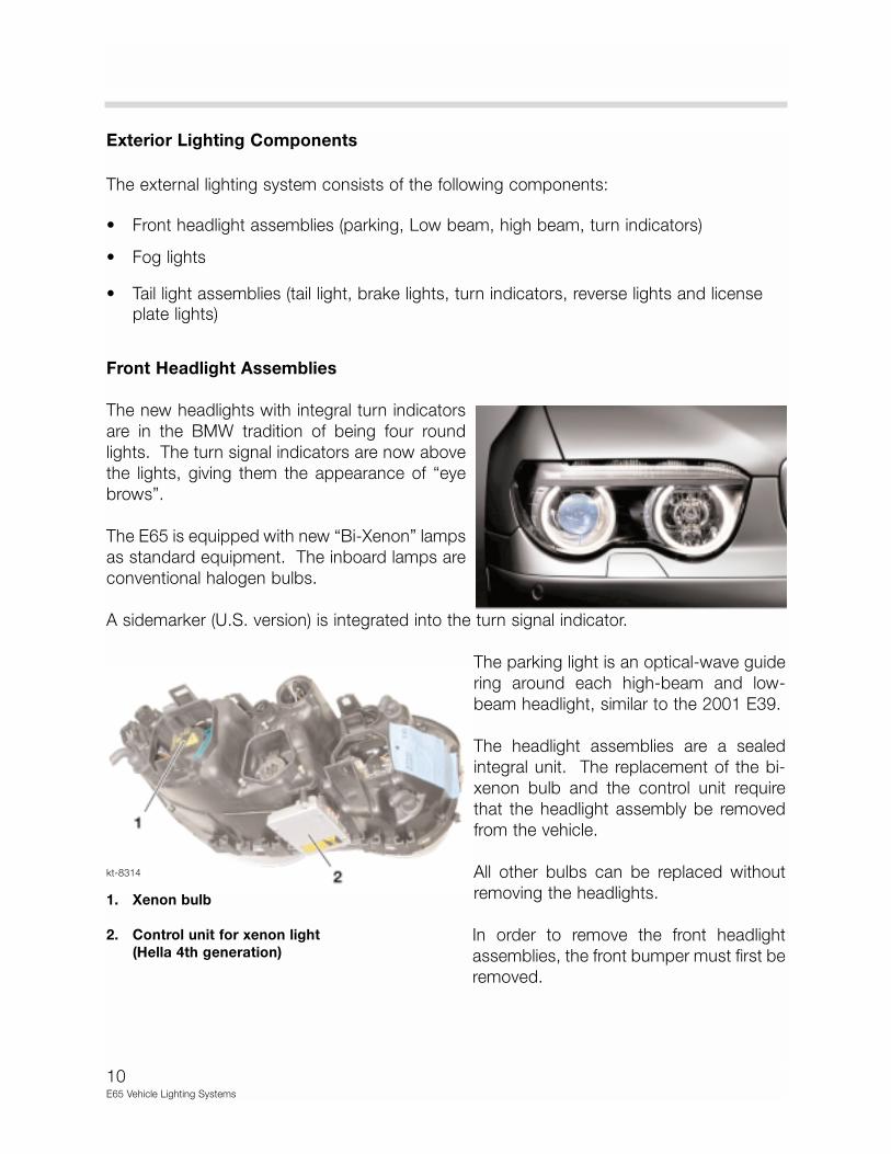
The parking light is an optical-wave guide
ring around each high-beam and low-
beam headlight, similar to the 2001 E39.
The headlight assemblies are a sealed
integral unit. The replacement of the bi-
xenon bulb and the control unit require
that the headlight assembly be removed
from the vehicle.
All other bulbs can be replaced without
removing the headlights.
In order to remove the front headlight
assemblies, the front bumper must first be
removed.
kt-8314
1. Xenon bulb
2. Control unit for xenon light
(Hella 4th generation)
11E65 Vehicle Lighting Systems
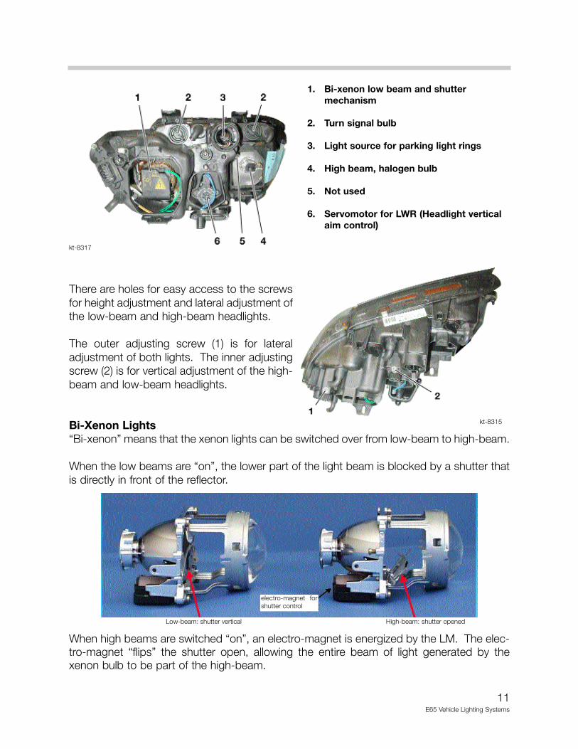
There are holes for easy access to the screwsfor height adjustment and lateral adjustment ofthe low-beam and high-beam headlights.
The outer adjusting screw (1) is for lateraladjustment of both lights. The inner adjustingscrew (2) is for vertical adjustment of the high-beam and low-beam headlights.
Bi-Xenon Lights“Bi-xenon” means that the xenon lights can be switched over from low-beam to high-beam.
When the low beams are “on”, the lower part of the light beam is blocked by a shutter thatis directly in front of the reflector.
When high beams are switched “on”, an electro-magnet is energized by the LM. The elec-tro-magnet “flips” the shutter open, allowing the entire beam of light generated by thexenon bulb to be part of the high-beam.
1. Bi-xenon low beam and shutter mechanism
2. Turn signal bulb
3. Light source for parking light rings
4. High beam, halogen bulb
5. Not used
6. Servomotor for LWR (Headlight vertical aim control)
kt-8317
kt-8315
electro-magnet forshutter control
Low-beam: shutter vertical High-beam: shutter opened
12E65 Vehicle Lighting Systems
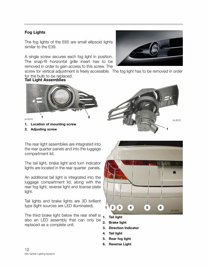
Fog Lights
The fog lights of the E65 are small ellipsoid lightssimilar to the E39.
A single screw secures each fog light in position.The snap-fit horizontal grille insert has to beremoved in order to gain access to this screw. Thescrew for vertical adjustment is freely accessible. The fog light has to be removed in orderfor the bulb to be replaced.Tail Light Assemblies
The rear light assemblies are integrated intothe rear quarter panels and into the luggagecompartment lid.
The tail light, brake light and turn indicatorlights are located in the rear quarter panels.
An additional tail light is integrated into theluggage compartment lid, along with therear fog light, reverse light and license platelight.
Tail lights and brake lights are 3D brillianttype (light sources are LED illuminated).
The third brake light below the rear shelf isalso an LED assembly that can only bereplaced as a complete unit.
1. Location of mounting screw
2. Adjusting screw
1. Tail light
2. Brake light
3. Direction Indicator
4. Tail light
5. Rear fog light
6. Reverse Light
kt-8310 kt-8312
kt-8300
13E65 Vehicle Lighting Systems
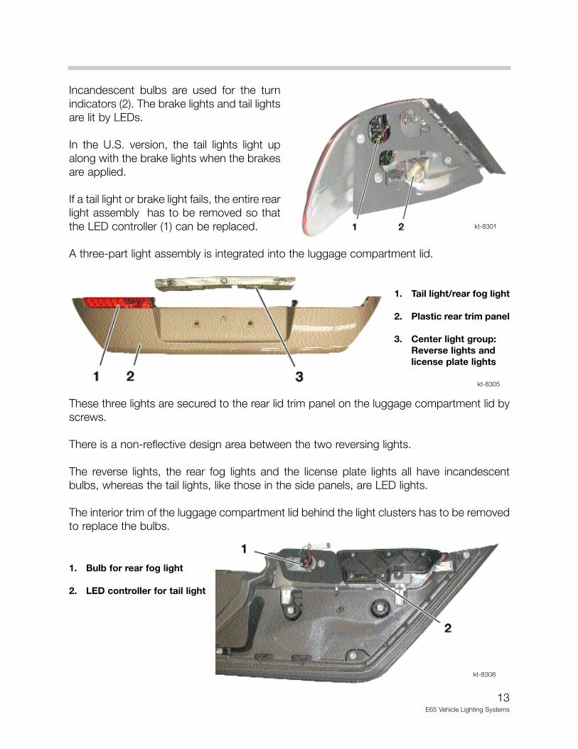
Incandescent bulbs are used for the turnindicators (2). The brake lights and tail lightsare lit by LEDs.
In the U.S. version, the tail lights light upalong with the brake lights when the brakesare applied.
If a tail light or brake light fails, the entire rearlight assembly has to be removed so thatthe LED controller (1) can be replaced.
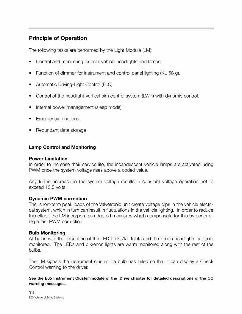
A three-part light assembly is integrated into the luggage compartment lid.
These three lights are secured to the rear lid trim panel on the luggage compartment lid byscrews.
There is a non-reflective design area between the two reversing lights.
The reverse lights, the rear fog lights and the license plate lights all have incandescentbulbs, whereas the tail lights, like those in the side panels, are LED lights.
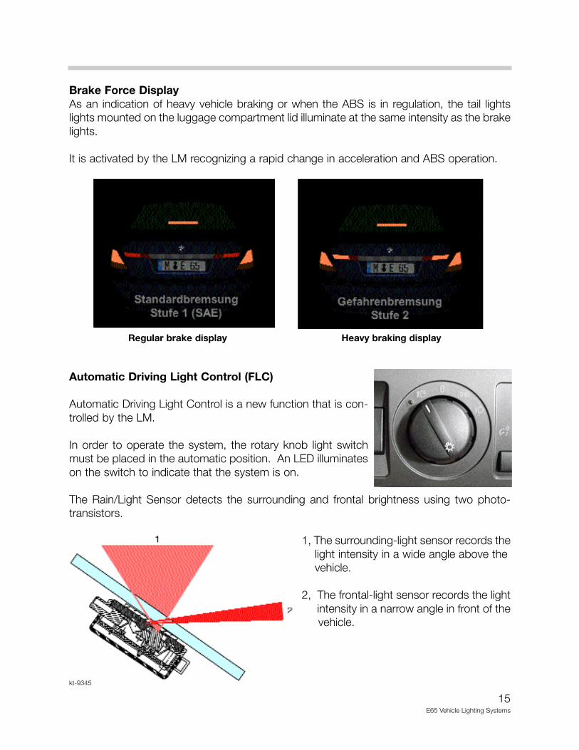
The interior trim of the luggage compartment lid behind the light clusters has to be removedto replace the bulbs.
kt-8301
kt-8305
1. Tail light/rear fog light
2. Plastic rear trim panel
3. Center light group:Reverse lights andlicense plate lights
1. Bulb for rear fog light
2. LED controller for tail light
kt-8308
14E65 Vehicle Lighting Systems
Principle of Operation
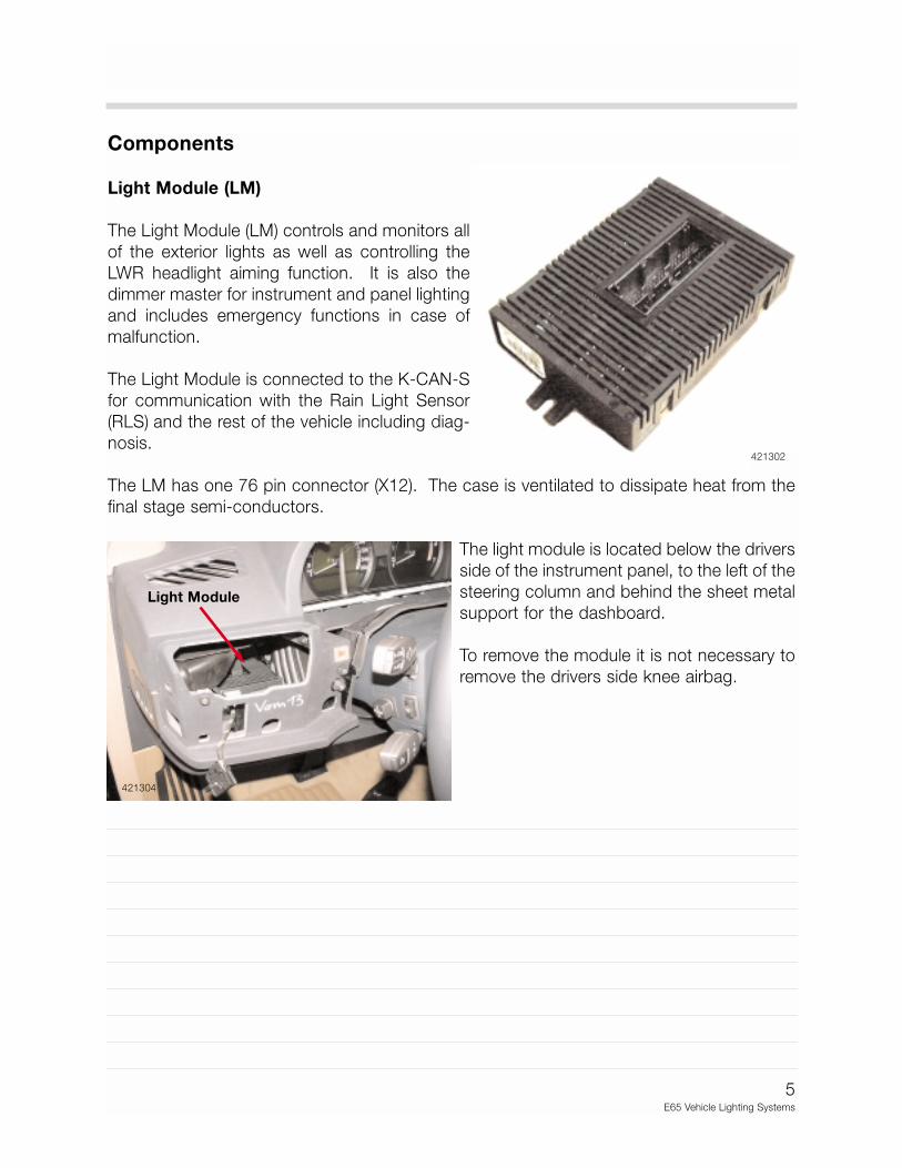
The following tasks are performed by the Light Module (LM):
• Control and monitoring exterior vehicle headlights and lamps.
• Function of dimmer for instrument and control panel lighting (KL 58 g).
• Automatic Driving-Light Control (FLC).
• Control of the headlight-vertical aim control system (LWR) with dynamic control.
• Internal power management (sleep mode)
• Emergency functions.
• Redundant data storage
Lamp Control and Monitoring
Power LimitationIn order to increase their service life, the incandescent vehicle lamps are activated usingPWM once the system voltage rises above a coded value.
Any further increase in the system voltage results in constant voltage operation not toexceed 13.5 volts.
Dynamic PWM correctionThe short-term peak loads of the Valvetronic unit create voltage dips in the vehicle electri-cal system, which in turn can result in fluctuations in the vehicle lighting. In order to reducethis effect, the LM incorporates adapted measures which compensate for this by perform-ing a fast PWM correction.
Bulb MonitoringAll bulbs with the exception of the LED brake/tail lights and the xenon headlights are coldmonitored. The LEDs and bi-xenon lights are warm monitored along with the rest of thebulbs.
The LM signals the instrument cluster if a bulb has failed so that it can display a CheckControl warning to the driver.
See the E65 Instrument Cluster module of the iDrive chapter for detailed descriptions of the CCwarning messages.
15E65 Vehicle Lighting Systems
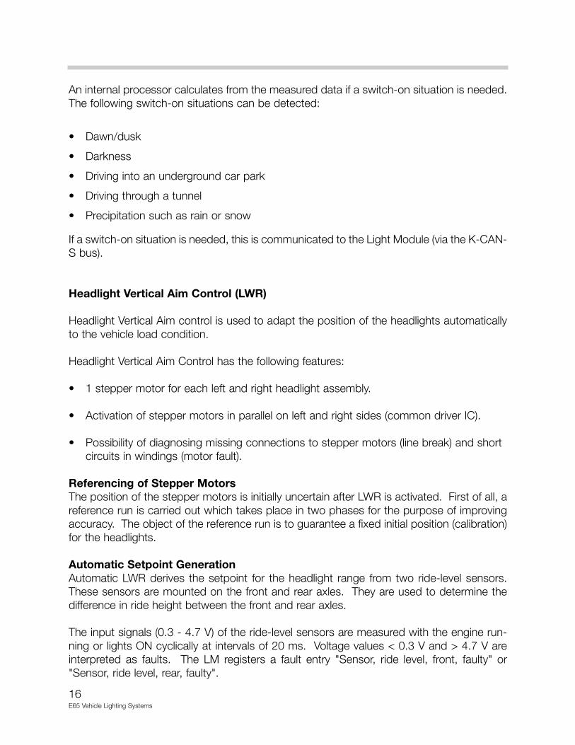
Brake Force Display As an indication of heavy vehicle braking or when the ABS is in regulation, the tail lightslights mounted on the luggage compartment lid illuminate at the same intensity as the brakelights.
It is activated by the LM recognizing a rapid change in acceleration and ABS operation.
Automatic Driving Light Control (FLC)
Automatic Driving Light Control is a new function that is con-trolled by the LM.
In order to operate the system, the rotary knob light switchmust be placed in the automatic position. An LED illuminateson the switch to indicate that the system is on.
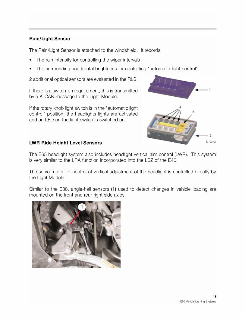
The Rain/Light Sensor detects the surrounding and frontal brightness using two photo-transistors.
1, The surrounding-light sensor records thelight intensity in a wide angle above the vehicle.
2, The frontal-light sensor records the lightintensity in a narrow angle in front of the vehicle.
Regular brake display Heavy braking display
kt-9345
16E65 Vehicle Lighting Systems
An internal processor calculates from the measured data if a switch-on situation is needed.The following switch-on situations can be detected:
• Dawn/dusk
• Darkness
• Driving into an underground car park
• Driving through a tunnel
• Precipitation such as rain or snow
If a switch-on situation is needed, this is communicated to the Light Module (via the K-CAN-S bus).
Headlight Vertical Aim Control (LWR)
Headlight Vertical Aim control is used to adapt the position of the headlights automaticallyto the vehicle load condition.
Headlight Vertical Aim Control has the following features:
• 1 stepper motor for each left and right headlight assembly.
• Activation of stepper motors in parallel on left and right sides (common driver IC).
• Possibility of diagnosing missing connections to stepper motors (line break) and short circuits in windings (motor fault).
Referencing of Stepper MotorsThe position of the stepper motors is initially uncertain after LWR is activated. First of all, areference run is carried out which takes place in two phases for the purpose of improvingaccuracy. The object of the reference run is to guarantee a fixed initial position (calibration)for the headlights.
Automatic Setpoint GenerationAutomatic LWR derives the setpoint for the headlight range from two ride-level sensors.These sensors are mounted on the front and rear axles. They are used to determine thedifference in ride height between the front and rear axles.
The input signals (0.3 - 4.7 V) of the ride-level sensors are measured with the engine run-ning or lights ON cyclically at intervals of 20 ms. Voltage values < 0.3 V and > 4.7 V areinterpreted as faults. The LM registers a fault entry "Sensor, ride level, front, faulty" or"Sensor, ride level, rear, faulty".
17E65 Vehicle Lighting Systems
Dynamic Headlight Vertical Aim ControlThe effect of dynamic LWR, is that the headlight aim is corrected immediately in critical dri-ving situations (extreme braking; heavy acceleration).
In this way, reduced headlight aim under certain circumstances (e.g. during braking) isimmediately corrected by the process of the head lights being "raised".
Also, the dazzling of other road users is eliminated during acceleration by the process ofthe headlights being "lowered".
The problem of incorrect interpretations (e.g. irregular road surface) is avoided by the useof more signals than just the ride-level signals.
It can usually be assumed that a braking operation is always accompanied by a simultane-ously actuated brake-light switch. However, the brake-light switch is not actuated duringacceleration. The vehicle speed is included in the correction calculation.
Dynamic Compensation During Braking: Because of the "system knowledge" thatcompensation of the headlight aim during braking is particularly more important when brak-ing at high speeds, dynamic LWR can dampen compensation of the headlight aim at lowspeeds.
Dynamic compensation during braking begins "gradually" above the minimum speed ofapprox. 40 km/h (25mph) and reaches its full effect from a speed of approx. 80 km/h(50mph).
As long as the brake light switch is not actuated, there is no dynamic compensation forbraking.
Dynamic Compensation During Acceleration: Acceleration is more "probable" thelower the initial speed is. Absolute accelerating performance decreases as speed increas-es because the vehicle is being driven in higher gears and therefore less torque is available.
Complete dynamic compensation takes place during acceleration as long as the speed isless than approx. 50 km/h (31mph). The effect of dynamic compensation decreasesincreasingly above this speed and disappears from a speed of approx. 110 km/h (68mph).
When the brake light switch is actuated, there is no dynamic compensation for accelera-tion.
18E65 Vehicle Lighting Systems
Activation of Stepper MotorsFunctions of the software driver for activating the stepper motors:
• Positioning of stepping motors (powering, acceleration and deceleration).
• Carrying out a reference run (each time LWR is activated).
• Inclusion of current actual step counter.
• Setpoint/actual-value comparison of step position.
• Activation of stepping-motor driver.
Internal Power Management (Sleep Mode)
Because the LM's operating current consumption would place unwanted load on the vehi-cle battery during long periods of parking and when its functions are not needed, it is pro-vided with mechanisms for identifying out-of-service periods and reducing the powerrequirement while retaining wake-up readiness.
The micro-processor of the LM functions with nominal operating current when:
• The CAN is active.
• Terminal R (input) is active.
• Terminal 15 (input) is active.
• Lamp functions are active.
• Anti-theft alarm-system alarm is active.
• The follow-me-home light circuit is active.
If none of the above conditions apply, the LM transmits it’s sleep readiness and then switch-es into sleep mode. It also switches into this mode when the sleep conditions are in placeand the sleep acknowledge bit has been received from another bus user.
After approx. 30 s the current consumption drops from approx. 120 mA to below 1 mA.The LM awakens cyclically and input signals are monitored so that the system can respondto possible changes in the switch states and the external inputs.
A CAN telegram received during this power-saving mode results in system wake-up.Following a wake-up period of max. 100 ms, the LM is again ready for communication, rel-evant telegrams are fully received and evaluated in each case so that no bus information islost.
19E65 Vehicle Lighting Systems
If no wake-up condition occurs for a period exceeding 390 s, the switch inputs are nolonger monitored and the zero-signal current is reduced further.
System wake-up is possible by CAN telegrams, an activated terminal 15 or the hazard-warning button.
Redundant Data Storage
The LM shares responsibility with the CAS for the storage of the Vehicle IdentificationNumber and the FA (Vehicle Order).
Emergency Functions
The system is equipped with hardware that is completely independent from the processorin order to safeguard the functions needed for driving safety should the processor or oneof its elements malfunction.
Emergency operation provides the following functions:
With terminal 15 ON, the following components are activated regardless of the position ofthe light switch:
• Low-beam headlights, left and right• Rear lamps/brake lights, left and right (outer)
With terminal 15 ON and actuated brake-light switch:
• Brake lights, left and right
Turn-signal and hazard-warning flashers, high beam, headlight flasher, front fog lamps, rearfog light and the 3rd brake light cannot be activated. Communication via K-CAN-S is notpossible.
20E65 Vehicle Lighting Systems
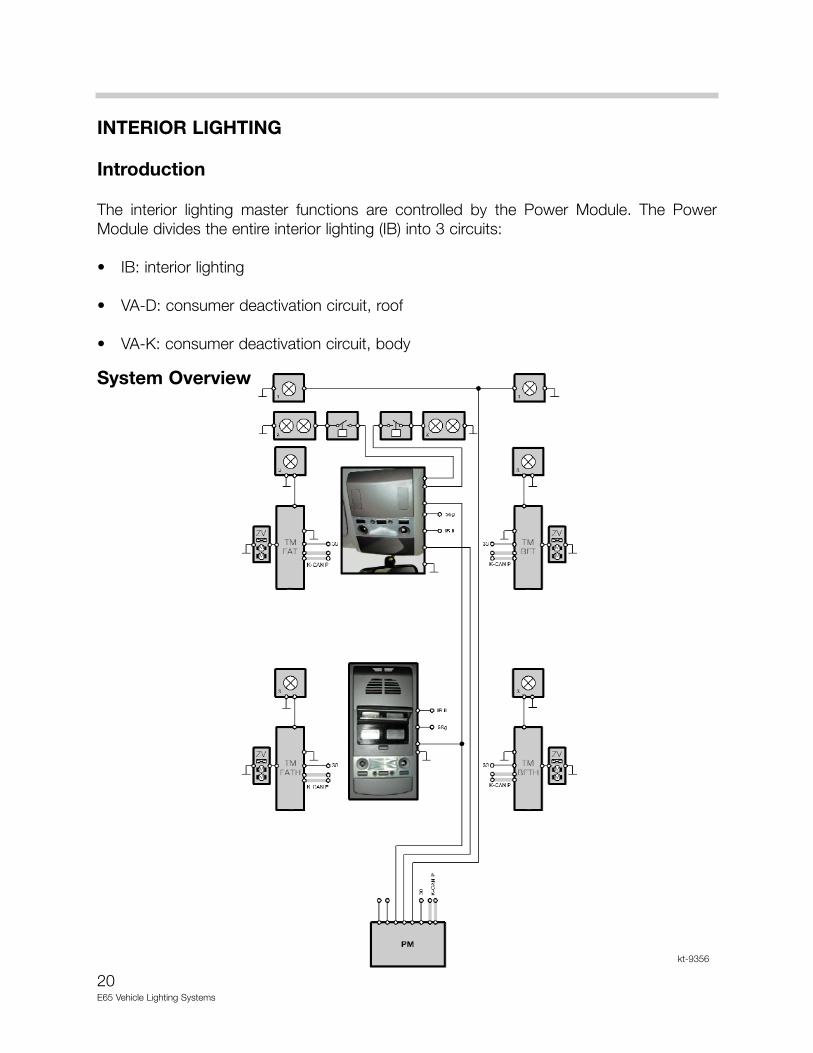
INTERIOR LIGHTING
Introduction
The interior lighting master functions are controlled by the Power Module. The PowerModule divides the entire interior lighting (IB) into 3 circuits:
• IB: interior lighting
• VA-D: consumer deactivation circuit, roof
• VA-K: consumer deactivation circuit, body
System Overview
kt-9356
21E65 Vehicle Lighting Systems
Components
The interior lighting includes the following lights:
External Door Handle Lighting (Visual Entry Aid)
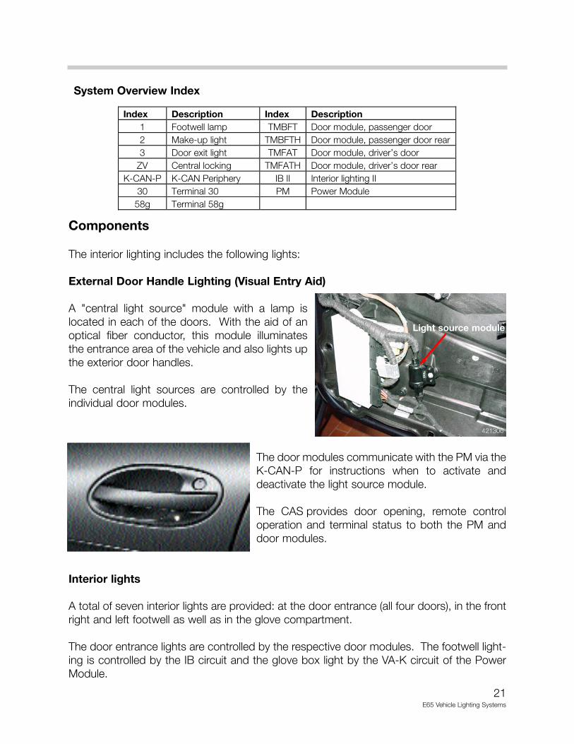
A "central light source" module with a lamp islocated in each of the doors. With the aid of anoptical fiber conductor, this module illuminatesthe entrance area of the vehicle and also lights upthe exterior door handles.
The central light sources are controlled by theindividual door modules.
The door modules communicate with the PM via theK-CAN-P for instructions when to activate anddeactivate the light source module.
The CAS provides door opening, remote controloperation and terminal status to both the PM anddoor modules.
Interior lights
A total of seven interior lights are provided: at the door entrance (all four doors), in the frontright and left footwell as well as in the glove compartment.
The door entrance lights are controlled by the respective door modules. The footwell light-ing is controlled by the IB circuit and the glove box light by the VA-K circuit of the PowerModule.
Index Description Index Description 1 Footwell lamp TMBFT Door module, passenger door 2 Make-up light TMBFTH Door module, passenger door rear 3 Door exit light TMFAT Door module, driver’s door
ZV Central locking TMFATH Door module, driver’s door rear K-CAN-P K-CAN Periphery IB II Interior lighting II
30 Terminal 30 PM Power Module 58g Terminal 58g
System Overview Index
Light source module
421306
22E65 Vehicle Lighting Systems
Front Interior Light Roof Console
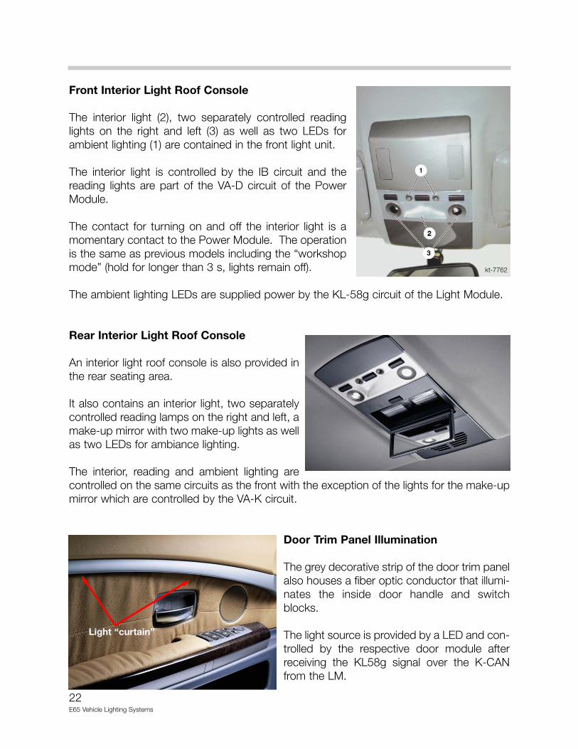
The interior light (2), two separately controlled readinglights on the right and left (3) as well as two LEDs forambient lighting (1) are contained in the front light unit.
The interior light is controlled by the IB circuit and thereading lights are part of the VA-D circuit of the PowerModule.
The contact for turning on and off the interior light is amomentary contact to the Power Module. The operationis the same as previous models including the “workshopmode” (hold for longer than 3 s, lights remain off).
The ambient lighting LEDs are supplied power by the KL-58g circuit of the Light Module.
Rear Interior Light Roof Console
An interior light roof console is also provided inthe rear seating area.
It also contains an interior light, two separatelycontrolled reading lamps on the right and left, amake-up mirror with two make-up lights as wellas two LEDs for ambiance lighting.
The interior, reading and ambient lighting arecontrolled on the same circuits as the front with the exception of the lights for the make-upmirror which are controlled by the VA-K circuit.
Door Trim Panel Illumination
The grey decorative strip of the door trim panelalso houses a fiber optic conductor that illumi-nates the inside door handle and switchblocks.
The light source is provided by a LED and con-trolled by the respective door module afterreceiving the KL58g signal over the K-CANfrom the LM.
Light “curtain”
kt-7762
23E65 Vehicle Lighting Systems
Interior Lighting Switching Criteria
Switch-On Criteria:
• Door open
• Terminal R off if KL 58g is active or has been active in the past 32 s.
• IB on by remote control (8 s search function).
• ZV unlocked by the crash sensor.
• ZV unlocked by remote control.
• By pulling on external door handle with terminal R off.
Switch-Off Criteria:
• All doors closed with terminal R or 15 on.
• All doors closed after 20 s switch-off delay with terminal R off.
• Terminal R off (if KL 58g has been active at least once inside the last 32 s) after 20 s switch-off delay.
• IB on by remote control (search function) after 8 s.
• IB on by remote control unlocking after 20 s.
• With door permanently open after 16 min.
• With all doors closed and ZV locked.
• Interior-light switch OFF.
24E65 Vehicle Lighting Systems
Review Questions:
1. What is the communication path used to inform the Light Module of a turn signal request? How are the turn signals cancelled?
2. What is the difference between a xenon light and a bi-xenon light?
3. How is the FLC system activated? How is a switch on request received by the LM?
4. Which control unit controls the LWR function? What makes this a “Dynamic” system?
5. Describe the communication and control unit operation required to turn on the interior lights when unlocking the vehicle via the Remote Control.


![[Code List] E65/E66 Available Coding List Page 1 of 8morski-online.pl/ftp/e65-e66-available-coding-list.pdf · New Posts Private Messages FAQ ... englisch english [Code List] E65/E66](https://static.documents.pub/doc/80x56/5a856b6e7f8b9ac96a8c628f/code-list-e65e66-available-coding-list-page-1-of-8morski-posts-private-messages.jpg)


