Deformation Mechanisms, Rheology and Tectonics Programme and Abstracts 19 th International Conference on Deformation Mechanisms, Rheology and Tectonics 16-18 September 2013, Leuven, Belgium
Transcript
Deformation Mechanisms,
Rheology and
Tectonics
Programme and Abstracts
19th International Conference on Deformation Mechanisms, Rheology and Tectonics
16-18 September 2013, Leuven, Belgium
Deformation Mechanisms,
Rheology and
Tectonics
Programme and Abstracts
19th International Conference on Deformation Mechanisms, Rheology
and Tectonics
16-18 September 2013 Leuven, Belgium
Geodynamics & Geofluids Research Group Department of Earth & Environmental Sciences
KU Leuven Belgium
This volume was edited by Tom Haerinck, Koen Torremans and Manuel Sintubin Cover design by Koen Torremans Cover photo: Photo collage of early-orogenic regularly spaced layer-perpendicular veins in the Rursee area, mullions at Dedenborn, ‘boudins’ at Bastogne and late-orogenic discordant veins at Herbeumont – Photo credentials: Manuel Sintubin, Koen Van Noten & Hervé Van Baelen
All rights reserved. Except in those cases expressly determined by law, no part of this publication may be multiplied, saved in an automated data file or made public in any way whatsoever without the express prior written consent of the publishers.
Deformation Mechanisms, Rheology and Tectonics Programme and Abstracts
International Conference, Leuven 2013
1
Preface
Dear colleagues,
We are very pleased to welcome you to Leuven for the 19th International Conference on Deformation mechanisms, Rheology and Tectonics. We hope to offer you the forum to have 3 days of lively discussions on our research on natural structures and microstructures.
DRT2013 in Leuven is also dedicated to Henk Zwart, the ‘founding father’ of the DRT tradition, who sadly passes away last year. To commemorate the legacy of Henk Zwart, the IUGS TecTask has inaugurated the Henk Zwart Award. We have the privilege to award the inaugural award during the DRT2013 in Leuven.
Financial support for international invited speakers has been provided by the ESF research networking programme Micro-DICE and the KU Leuven Geodynamics and Geofluids Research Group. TecTask, the IUGS Commission on Tectonics and Structural Geology, has provided travel grants for early career scientists to attend DRT2013. Also Badley Geoscience Limited is acknowledged for their financial support.
We want to take advantage of this occasion to express our special thanks to the ‘invisible’ support of our financial manager, Ria Mattheus, and our web manager, Greet Willems, as well as the other members of the administrative staff of the Department of Earth and Environmental Sciences at the KU Leuven. Also the technical and logistic staff of the KU Leuven is acknowledged for their support.
The DRT2013 team – Tine Derez, Dominique Jacques, Tom Haerinck, Koen Torremans and Manuel Sintubin – hopes that you have a great time in Leuven, not only enjoying a hopefully succesful conference, but also the pleasures Leuven has to offer.
The DRT2013 team Leuven, September 2013
Programme and Abstracts Deformation Mechanisms, Rheology and Tectonics
International Conference, Leuven 2013
2
About DRT
Some history
In 1976 Henk Zwart, Richard Lisle, Gordon Lister and Paul Williams organised a meeting at the Geologisch en Mineralogisch Instituut der Rijksuniversiteit Leiden (The Netherlands) on Fabrics, Microtextures and Microtectonics. Their aim was to ‘bring together as many as possible of the people active in this field; not only geologists but also material scientists from other disciplines’ (Lister et al., 19771). In 1985, at the 5th meeting in Utrecht (The Netherlands) a biannual tradition has been installed. Eversince, the meeting is hosted every two years by a different European university. In 1999, at the 12th meeting in Neustadt an der Weinstrasse (Germany), the conference series got its brand name ‘Deformation mechanisms, Rheology and Tectonics’ (Dresen & Handy, 20012) or DRT.
The DRT meetings are devoted to the study of deformation behaviour and rheology of minerals, rocks and materials. Dialogue is encouraged on all scales of field, experimental and theoretical studies of rock deformation. DRT aims to provide the main forum in Europe where field geologists, experimentalists and modellers could debate the problems and questions posed by natural structures and microstructures (Schmid et al., 19993).
To date, three DRT meetings have taken place in The Netherlands and Switzerland; two meetings in Germany, the U.K. and France; and one meeting in Sweden, Austria, Czech Republic, Italy and Spain.
1 LISTER, G.S., WILLIAMS, P.F., ZWART, H.J. & LISLE, R.J. (eds) 1977. Tectonophysics 39, 1-487. 2 DRESEN, G. & HANDY, M. (eds) 2001. International Journal of Earth Sciences (Geologische Rundschau) 90, 1-210. 3 SCHMID, S.M., HEILBRONNER, R. & STÜNITZ, H. (eds) 1999. Tectonophysics 303, 1-319.
Deformation Mechanisms, Rheology and Tectonics Programme and Abstracts
International Conference, Leuven 2013
Committees
Organizing committee Manuel Sintubin, KU Leuven, Belgium – conference manager Tom Haerinck, KU Leuven, Belgium – secretary Koen Torremans, KU Leuven, Belgium Marc Seefeldt, KU Leuven, Belgium Sergio Llana-Fúnez, Universidad de Oviedo, Spain – organiser DRT2011 Scientific committee Hans de Bresser, Utrecht University, The Netherlands Martyn Drury, Utrecht University, The Netherlands Alison Ord, The University of Western Australia, Australia Cees Passchier, Johannes Gutenberg Universität Mainz, Germany Frederick J. Simons, Princeton University, USA Chris Spiers, Utrecht University, The Netherlands Janos Urai, RWTH Aachen, Germany Ilka Weikusat, Alfred-Wegener Institut für Polar- und Meeresforschung, Germany Hans-Rudolf Wenk, University of California, Berkeley, USA Organisation of the field trip Manuel Sintubin, KU Leuven, Belgium Tom Haerinck, KU Leuven, Belgium Koen Torremans, KU Leuven, Belgium Tine Derez, KU Leuven, Belgium Dominique Jacques, KU Leuven, Belgium
Programme and Abstracts Deformation Mechanisms, Rheology and Tectonics
International Conference, Leuven 2013
4
In memoriam – Henk Zwart 1924-2012
On November 18, 2012 we were informed of the death of one of the pioneers of modern structural geology, Henk Zwart.
Henk studied geology in Leiden and did his PhD work in the St Barthelemy Massif, French Pyrenees, supervised by Prof. de Sitter. During and after his PhD work, he became interested in the relationship between metamorphism and deformation. For several years, he cooperated in a large mapping program that covered the central Pyrenees, supervised by de Sitter, with a large number of PhD students. His supervisor, Prof. de Sitter, forbade him to work on the metamorphic rocks since, he said, they were too difficult to understand. This was of course a challenge to Henk Zwart, who concentrated all his efforts on the metamorphic rocks. He cut
numerous thin sections, but could indeed not make much progress. At the time, it was standard practice to cut thin sections normal to the lineation. One day, the thin section maker in Leiden made a mistake and cut some of the metamorphic rocks in the Pyrenees parallel to the lineation: in these sections, Henk Zwart for the first time saw the pre-syn and postkinematic interference patterns of foliation and porphyroblasts with which we are now all familiar. He then brought all his rocks back to the thin section maker, and from then on all sections were cut parallel to the lineation, in Leiden and abroad. This was probably Henk's most lasting discovery in structural geology: serendipity indeed ...
After the Pyrenees work with de Sitter, Henk worked some time in Denmark before he obtained the position as Professor in structural geology in Leiden. He had this chair till the department moved to Utrecht in the beginning of the 1980s. Besides his work in the Pyrenees, Henk is famous for fundamental work on the difference between "Variscan type" and "Alpine type" orogenies. He supervised large mapping projects in Scandinavia and in the Pyrenees, and was active in several leading scientific organisations, notably in the construction of the maps of the European Variscides.
Deformation Mechanisms, Rheology and Tectonics Programme and Abstracts
International Conference, Leuven 2013
Henk was chairman of ComTect, the predecessor of TecTask. In 1976 he organised a meeting at Leiden in collaboration with Richard Lisle, Gordon Lister and Paul Williams from the Geologisch en Mineralogisch Instituut der Rijksuniversiteit, that went on to become the Deformation Mechanisms Rheology and tectonics conference series. Henk was an extremely capable and successful scientist, and one of the founders of European structural geology and metamorphic petrology. On a more personal level, Henk was also a mountaineer, climbed the Matterhorn with Rudolph Trouw, and was famous for being a rather "silent " person. He could bring students to despair by not saying anything during an entire dinner or evening together...
Cees Passchier, November 2012
Photographs: Henk Zwart in Galicia (1971). Courtesy of Jordi Carreras.
Henk Zwart Award – IUGS TecTask
To commemorate the legacy of Henk Zwart, TecTask, the IUGS Commission on Tectonics and Structural Geology, inaugurated the Henk Zwart Award, to further promote research in structural geology and tectonics in any of its fields. The award aims at rewarding scientists who made an outstanding contribution in elevating science in structural geology and who has shown through publication record and actions to have promoted structural geology.
The inaugural Henk Zwart Award will be awarded during DRT2013
Programme and Abstracts Deformation Mechanisms, Rheology and Tectonics
International Conference, Leuven 2013
6
Sponsors & supporters
International Union of Geological Sciences
Commission on Tectonics and Structural Geology www.tectask.org
Micro-DICE
ESF research networking programme on the Micro-Dynamics of Ice
Deformation Mechanisms, Rheology and Tectonics Programme and Abstracts
International Conference, Leuven 2013
Programme at a glance
Programme and Abstracts Deformation Mechanisms, Rheology and Tectonics
International Conference, Leuven 2013
8
Lunch in Leuven
There is no organised lunch during the DRT 2013 conference. However, lunch options in the vicinity of the conference are abundant with a wide variety of sandwich bars, restaurants and fastfood branches. A few tips of the organizing committee are listed in the map below.
Deformation Mechanisms, Rheology and Tectonics Programme and Abstracts
International Conference, Leuven 2013
Programme and Abstracts Deformation Mechanisms, Rheology and Tectonics
International Conference, Leuven 2013
10
Deformation Mechanisms, Rheology and Tectonics Programme and Abstracts
International Conference, Leuven 2013
Oral Programme
Programme and Abstracts Deformation Mechanisms, Rheology and Tectonics
International Conference, Leuven 2013
12
Monday September 16th
08:30 - ... Registration
09:00 – 09:10 Opening and welcome
SESSION 1: FABRICS & MICROSTRUCTURES
Chair: Jordi Carreras
09:10 – 09:40 keynote
Montési L.G.J., Gueydan F., Précigout J. Fabric evolution, localization, and strain-dependent strength profiles for the continental lithosphere
09:40 – 10:00 Satsukawa T., Mizukami T., Morishita T. Natural constrains on the dynamics of the uppermost mantle evolution during the initial stage of back-arc spreading
10:00 – 10:20 Llana-Fúnez S., Brown D. Seismic velocities from laboratory measurements and crystallographic preferred orientation across a surface analog of the continental Moho at Cabo Ortegal, Spain
10:20 – 10:40 Mukherjee M.K. Contrasting deformation Geometry, Kinematics and Microstructures between the Basement and the Mesoproterozoic cover rocks of the Kaladgi Basin, Southwestern India: indications towards deformation of the cover by gravity gliding along a detached unconformity
10:40 – 11:10 Break
SESSION 2: FLUIDS IN A DEFORMING ENVIRONMENT (1/3)
Chair: Virginia Toy
11:10 – 11:30 Piazolo S., Koehn D., Vass A., Daczko N. Melt migration in the lower crust by melt induced fracturing and reaction: Insights from field studies combined with numerical modelling
11:30 – 11:50 Pittarello L., Habler G., Abart R. Garnet growth in frictional melts
11:50 – 12:10 Ganzhorn A.C., Arbaret L., Trap P., Champallier R., Labrousse L., Prouteau G. Impact of textural anisotropy on syn-kinematic partial melting of natural gneisses: an experimental approach
Deformation Mechanisms, Rheology and Tectonics Programme and Abstracts
International Conference, Leuven 2013
12:10 – 12:30 Triantafyllou A., Berger J., Diot, Ennih N., Monnier C., Plissart G., Baele J.M., Vandycke S. The Neoproterozoic Iriri complex (Moroccan Anti-Atlas): insights into igneous, metamorphic and tectonic evolution of a middle oceanic arc crust
12:30 – 14:00 Lunch break
SESSION 3: DEFORMATION MECHANISMS, FROM EXPERIMENT TO NATURE (1/2)
Chair: Laurent Montesi
14:00 – 14:30 keynote
Wenk H.R. From high pressure deformation experiments to anisotropy in the lowermost mantle
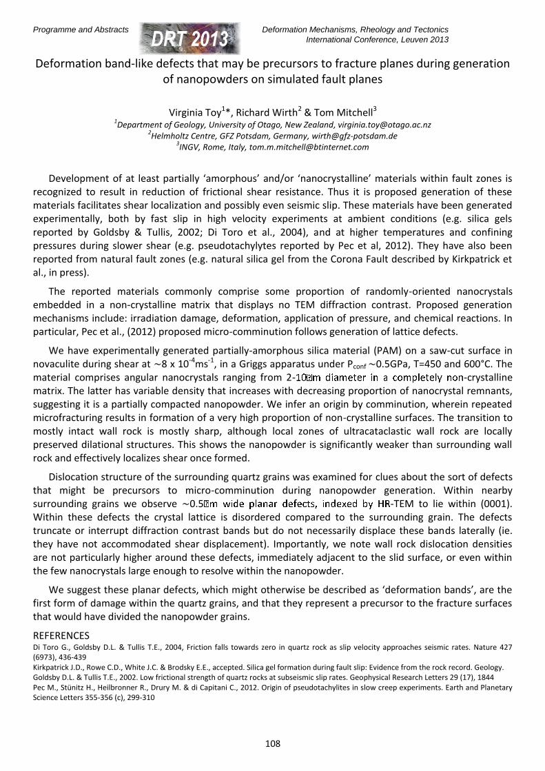
14:30 – 14:50 Toy V., Wirth R., Mitchell T. Deformation band-like defects that may be precursors to fracture planes during generation of nanopowders on simulated fault planes
14:50 – 15:10 Morgan S.S., Nábělek P.I., Student J. Fluid-controlled fast grain boundary migration recrystallization and switch in slip systems from prism [c] to prism <a> in a high strain, high temperature aureole, California, USA
15:10 – 15:30 Derez T., Jacques D., Pennock G., Drury M., Sintubin M. Deciphering the relationship between different types of low-temperature intracrystalline deformation microstructures in naturally deformed quartz
15:30 – 16:00 Break
SESSION 4: MICRODYNAMICS OF ICE – MICRO-DICE (1/2)
Chair: Hans de Bresser
16:00 – 16:30 keynote
Hansen L.N., Goldsby D.L., Kohlstedt D.L. The importance of grain-boundary sliding during deformation of geological materials
16:30 – 16:50 Piazolo S., Wilson C.J.L., Luzin V., Brouzet C., Peternell M. Dynamics of ice mass deformation: Linking processes to rheology, texture and microstructure
16:50 – 17:10 Montagnat M., Grennerat F., Chauve T., Barou F., Castelnau O., Vacher P. Deformation heterogeneities during creep and dynamic recrystallization in ice
17:10 – 18:30 POSTER SESSION
Programme and Abstracts Deformation Mechanisms, Rheology and Tectonics
International Conference, Leuven 2013
14
Tuesday September 17th
SESSION 5: FLUIDS IN A DEFORMING ENVIRONMENT (2/3)
Chair: Anne-Marie Boullier
08:30 – 09:00 keynote
Urai J.L., Holland M., Kraus W., Telle R., Arndt M., Virgo S. How good is the glue? An integrated investigation of the mechanical properties of rocks undergoing crack-seal processes, using field, experimental and numerical methods
09:00 – 09:20 Mamtani M.A., Mondal T.K. AMS, vein orientation, and 3D Mohr circle analyses from Gadag (southern India) – recognizing fluid pressure fluctuation and its significance in Gold mineralization
09:20 – 09:40 Torremans K., Muchez P., Sintubin M. Vein microstructures and vein property distributions at the Nkana Cu-Co deposit, Zambia
09:40 – 10:00 Schmatz J., Urai J.L., Sadler M. Carbonic Inclusions in Natural Rock Salt and their Role in Development of Microstructure
10:00 – 10:30 Break
SESSION 6: METHODS IN STRUCTURAL GEOLOGY (1/2)
Chair: Janos Urai
10:30 – 10:50 Walter J.M., Randau C., Stipp M., Leiss B., Ullemeyer K., Klein H., Hansen B.T., Kuhs W.F. New Perspectives for In-Situ Rock Deformation and Recrystallisation Analysis – POWTEX Neutron Diffractometer at FRM II Garching, Germany
10:50 – 11:10 Huet B., Yamato P., Grasemann B. Influence of metamorphic reactions on rock strength: A new analytical model
11:10 – 11:30 Lokajíček T. Laboratory approach to the study of elastic anisotropy on spheres by simultaneous longitudinal and transversal sounding under confining pressure
11:30 – 11:50 Svitek T., Lokajiček T., Petružálek M. Determination of elastic anisotropy from P- and S-waves based on ultrasonic sounding on spherical samples
11:50 – 12:50 GENERAL ASSEMBLY
Deformation Mechanisms, Rheology and Tectonics Programme and Abstracts
International Conference, Leuven 2013
12:50 – 14:00 Lunch break
SESSION 7: FLUIDS IN A DEFORMING ENVIRONMENT (3/3)
Chair: Sandra Piazolo
14:00 – 14:20
Boulton C., Toy V., DFDP-1 Scientific Party Rheological implications of fluid-rock interaction revealed in fault rock recovered during the Alpine Fault – Deep Fault Drilling Project (DFDP-1)
14:20 – 14:40 Poulet T., Veveakis E., Herwegh M., Regenauer-Lieb K. The origin and role of fluids in the Glarus Thrust: A fundamental multiphysics oscillator
14:40 – 15:00 Lommatzsch M., Exner U., Gier S. Formation of effective fluid barriers in unconsolidated sands through cataclasis and clay mineral diagenesis, as a result of localized deformation
15:00 – 15:30 Break
SESSION 8: MICRODYNAMICS OF ICE – MICRO-DICE (2/2)
Chair: Rudy Wenk
15:30 – 16:00 keynote
Peternell M., Wilson C.J.L., Dierckx M., Hammes D.M., Piazolo S. Microstructural evolution of polycrystalline ice using in situ deformation experiments and FAME
16:00 – 16:20 de Bresser H., Diebold S., Durham W. Using composite flow laws to investigate the role of grain size in the rheology of water ice
16:20 – 16:40 Seidemann M., Lilly K., Easingwood R., Prior D. Practical Cryo-EBSD on Fine-Grained Polycrystalline Ice: Obstacles and Solutions
16:40 – 18:30 POSTER SESSION
Programme and Abstracts Deformation Mechanisms, Rheology and Tectonics
International Conference, Leuven 2013
16
Wednesday September 18th
SESSION 9: DEFORMATION MECHANISMS, FROM EXPERIMENT TO NATURE (2/2)
Chair: Andre Niemeijer
08:30 – 08:50 Précigout J., Hirth G. B-type Olivine Fabric induced by Grain Boundary Sliding
08:50 – 09:10 Nachlas W.O., Whitney D.L., Teyssier C., Hirth G. Titanium solubility in naturally and experimentally deformed quartz
09:10 – 09:30 Cross A.J., Prior D.J, Hirth G., Meyers C. Grain size sensitive creep in experimentally deformed, fine-grained anorthite
09:30 – 09:50 Farla R., Amulele G., Girard J., Karato S. High pressure (~19 GPa) and temperature (~2000-2200 K) deformation experiments on polycrystalline wadsleyite in the rotational Drickamer apparatus
09:50 – 10:30 Break
SESSION 10: SHEAR-DOMINATED DEFORMATION,
FROM MICROSCALE TO LITHOSPHERIC SCALE
Chair: Sergio Llana Funez
10:30 – 11:00 keynote
Carreras J., Druguet E. Complex fold patterns arisen from progressive non-coaxial deformation of quartzite beds
11:00 – 11:20 Díaz-Azpiroz M., Barcos L., Balanyá J.C., Expósito I., Fernández C., Jiménez A., Czeck D., Faccena C. Flow and strain partitioning at multiple scales in a brittle-ductile transpressive deformation zone at the external Betics (southern Spain)
11:20 – 11:40 Noorsalehi-Garakani S., Urai J.L., Kettermann M. Clay-Gouge thickness and 3D fault zone architecture in normal faults - insights from water-saturated sandbox experiments
11:40 – 12:00 Bukovská Z., Jeřábek P., Lexa O., Morales L. The progressive development of shear bands from South Armorican Shear Zone, France
Deformation Mechanisms, Rheology and Tectonics Programme and Abstracts
International Conference, Leuven 2013
12:00 – 14:00 Lunch break
SESSION 11: VALORISATION TO SOCIETY
Chair: Sara Vandycke
14:00 – 14:30 keynote
Niemeijer A., Vissers R.L.M Earthquake rupture directivity inferred from depth-dependent frictional properties
14:30 – 14:50 Desbois G., Urai J.L., Höhne N., Bésuelle P., Viggiani G., Laurich B., Noorsalehi–Garakani S. Deformation mechanisms in experimentally deformed claystones from geological underground laboratories (Boom and Callovo-Oxfordian Clays): preliminary results
14:50 – 15:10 Laurich B., Desbois G., Nussbaum C., Vollmer C, Urai J.L. Evolution of microfabric of faults in the Opalinus Clay from the Mont Terri Underground Research Laboratory (CH): insights from multiscale studies using Ion Beam polishing and electron microscopy.
15:10 – 15:30 Pluymakers A., Peach C., Spiers C. Diagenetic compaction creep and healing of anhydrite fault gouge under static upper crustal conditions: microphysical mechanisms and implications for CO2 storage
15:30 – 16:00 Break
SESSION 12: METHODS IN STRUCTURAL GEOLOGY (2/2)
Chair: Manish Mamtani
16:00 – 16:20 Abe S., Urai J.L., Kettermann M. Discrete element modeling of boudinage in 2D and 3D: Insights on rock rheology, matrix flow, and evolution of 3D geometry
16:20 – 16:40 Peters M., Poulet T., Karrech A., Regenauer-Lieb K., Herwegh M. What initiates necking? An approach to link natural microstructures with elasto-visco-plastic numerical modeling of boudinage
16:40 – 17:00 Hossain S., Kruhl J.H. Fractal Geometry Based Quantification of Spatial Variation of Fracture Patterns: Ries Impact Crater, Germany
17:00 Closing
Programme and Abstracts Deformation Mechanisms, Rheology and Tectonics
International Conference, Leuven 2013
18
Deformation Mechanisms, Rheology and Tectonics Programme and Abstracts
International Conference, Leuven 2013
Poster Programme
Programme and Abstracts Deformation Mechanisms, Rheology and Tectonics
International Conference, Leuven 2013
20
SESSION A: DEFORMATION MECHANISMS, FROM EXPERIMENT TO NATURE
A01 R. Bruijn, J. Linckens, P. Skemer Dynamic recrystallization and phase mixing in experimentally deformed harzburgite
A02 C.M. Fadul, L. Lagoeiro, M. Egydio-Silva Using electron backscatter diffraction (EBSD) to measure microstructure of quartz ribbons
A03 C.C. Gonçalves, G. Hirth The role of quartz recrystallization on weak phase interconnection and strain localization
A04 T. Okudaira Grain-boundary diffusion rates inferred from grain-size variations of quartz in metacherts from a contact aureole
A05 B. Richter, R. Kilian, H. Stünitz, R. Heilbronner The effect of hot-pressing on the grain size distribution and microstructure of quartz gouge at the brittle-viscous-transition in shear experiments
A06 J.A. Tielke, L.N. Hansen, A.M. Dillman, D.L. Kohlstedt The role of grain-boundary sliding in deformation of olivine as determined from calculations of plasticity for experimentally deformed aggregates
A07 N.E. Timms, D. Healy The effects of anisotropic elastic properties on shock deformation microstructures in zircon and quartz
A08 L. Tokle, H. Stünitz, G. Hirth The effect of muscovite on the fabric evolution of quartz under general shear
Deformation Mechanisms, Rheology and Tectonics Programme and Abstracts
International Conference, Leuven 2013
SESSION B: FLUIDS AND MELTS IN A DEFORMING ENVIRONMENT
B01 Arndt M., Virgo S., Cox S.F., Urai J.L. Fracture controlled fluid pathways in a limestone high-pressure cell (Natih Formation, Oman Mountains): Insights from Stable Isotopes
B02 R. Dias, N. Moreira, A. Ribeiro, M. Hadani, P. Almeida Tardi-Variscan Deformation in Ibero-Moroccan Sector; Implications on Pangeia Assemblage
B03 S. Hemes, J. Klaver, G. Desbois, J.L. Urai Deformation of Boom Clay microstructure, due to compaction during Wood’s metal injection, as visualized by high resolution scanning electron microscopy and broad-ion beam milling
B04 D. Jacques, R. Vieira, P. Muchez, M. Sintubin Fractures, veins and mineral deposits at Minas da Panasqueira, Portugal – revisited
B05 S. Loveless, V. Bense Barrier to conduit-barrier hydraulic behaviour linked to fault throw in faults cutting poorly lithified sediment
B06 M. Pec, D.L. Kohlstedt, M. Zimmerman, B. Holtzman An experimental study of reactive melt migration in mantle rocks
B07 R. Veeningen, B. Grasemann, K. Decker, A. Hugh, N. Rice, D. Schneider Detailed microstructural characterization of a fractured Pan-African basement reservoir, central Yemen
B08 M. Voorn, U. Exner, S. Hoyer, T. Reuschlé Porosity and permeability analysis of fractured dolomites from a hydrocarbon reservoir
B09 T. Watanabe, M. Kitano A study on grain boundary brine in halite rocks using electrical conductivity measurements
Programme and Abstracts Deformation Mechanisms, Rheology and Tectonics
International Conference, Leuven 2013
22
SESSION C: SHEAR-DOMINATED DEFORMATION,
FROM MICROSCALE TO LITHOSPHERIC SCALE
C01 L. Demeuldre, A. Triantafyllou, S. Vandycke Tectonics and paleo-stress analysis in view to reconstruct the brittle deformation of the diorite intrusion of Lessines (Belgium)
C02 N.J. Hunter, P. Hasalová, R.F. Weinberg Strain partitioning in crustal shear zones: the effect of interconnected micaceous layers on quartz deformation
C03 S. Llana-Fúnez, F.J. Fernández Fault rocks at the core of the Valdoviño Fault (Variscan Orogen, NW Iberia)
C04 N. Moreira, R. Dias Domino Structures as a local accommodation process in heterogeneous shear zones
C05 I. Pereira, R. Dias, T. Bento dos Santos, J. Mata The Juzbado-Penalva do Castelo wrench ductile shear zone: a major structure oblique to the main Iberian Variscan trend
C06 S. Piazolo, J. Smith, N. Daczko The role of reaction progression and annealing on shear localization: Initiation of paired shear zones in the lower crust of Fiordland, New Zealand
C07 A. Raith, J.L. Urai, S. Abe DEM simulation based modeling of fault zone evolution in brittle-ductile layered rocks
C08 B.C. Rodrigues, J. Pamplona, M. Peternell, A. Moura, M. Schwindinger P-T Path of a Variscan Shear Zone recorded on Quartz-Aluminous Shearband Boudins
C09 P. Wehrens, R. Baumberger, M. Herwegh Alpine re-activation of pre-existing anisotropies: details from a large-scale shear zone in the Aar massif (Central Alps)
Deformation Mechanisms, Rheology and Tectonics Programme and Abstracts
International Conference, Leuven 2013
SESSION D: METHODS IN STRUCTURAL GEOLOGY
D01 T. Haerinck, T.N. Debacker, M. Sintubin The magnetocrystalline anisotropy of chloritoid single crystals investigated by directional magnetic hysteresis measurements and torque magnetometry
D02 D. M. Hammes, M. Peternell FAME – Software to determine rock microstructures
D03 D. Healy An integrated tensorial approach for characterising fractured rocks
D04 M. Kettermann, J. Röth, J.L. Urai Failure mode transition as result of effective stress – insights from analogue modeling using hemihydrate powder and sand
D05 M. Petružálek, T. Lokajíček and T. Svitek The influence of mutual orientation between foliation and loading direction on fracturing process of migmatite samples
D06 B.C. Rodrigues, J. Pamplona, M. Peternell, A. Moura, M. Schwindinger Quantification of Quartz Microstructures
D07 M. Schwindinger, M. Peternell, C. Benedito, B.C. Rodrigues, J. Pamplona Quantification of synmagmatic flow structures of the Vila Pouca de Aguiar Pluton, NW Portugal
D08 A. Soares, R. Dias Fry strain methodology; some constraints concerning initial point distributions
D09 H. van Gent, F. Strozyck, J.L. Urai, M. de Keijzer 3D internal structure of the Zechstein evaporites
D10 J.L. Urai, T. Berlage, M. Bublat, S. Virgo, C. Hilgers, P.A. Kukla ViP - a virtual polarizing microscopy system for microtectonics
D11 S. Virgo, S. Abe, J.L. Urai Structural Styles of Fracture-Vein Interaction: Insight into the Crack-Seal Process from 3D-DEM Modelling.
D12 S. Wex, C.W. Passchier, E.A. de Kemp, S. İlhan Meter-Scale Sheath Folds visualized in Ancient Roman Marble Wall Coverings from Ephesus, Turkey
Programme and Abstracts Deformation Mechanisms, Rheology and Tectonics
International Conference, Leuven 2013
24
SESSION E: FABRICS AND MICROSTRUCTURES
E01 T. Derez, D. Jacques, G. Pennock, M. Drury, M. Sintubin Low-temperature intracrystalline deformation microstructures in naturally deformed quartz, haven’t you noticed them in your samples?
E02 R. Ghosh Temperature prediction inside Main Central Thrust Zone from grain boundary migration studies, Bhagirathi River Valley (NW Himalaya, India)
E03 J. Grymonprez, T. Haerinck, A.M. Hirt, M. Sintubin Identifying the influence of the metamorphic mineralogy on the magnetic fabric of the Ordovician slates in the Stavelot-Venn basement inlier, Belgium
E04 T. Haerinck, T.N. Debacker, M. Sintubin AMS analysis of the Crozon fold-and-thrust belt of Central Armorica (Brittany, France)
E05 K.C. Rahul Identification of Deformational Features of Larji-Kullu-Rampur Window Area, Western Himalaya: Approach -Thin Sections Study
E06 R. Kühn, B. Leiss, M. Lapp, L. Geissler, C.H. Friedel Fold-related texture analyses in marble lenses from the Erzgebirge – implications for the kinematic fold development and associated deformation mechanisms
E07 S. Olivia, L. Lagoeiro, L. Simõe, P. Ferreira Application of EBSD for microstructure and texture analysis of peridotites from the São Pedro Island group in São Paulo
E08 P. Puelles, J.J. Esteban, A. Beranoaguirre, J.I. Gil Ibarguchi, M. Mendia Petrofabric and microstructural analysis as a tool to unravel operating pre- and post-peak deformation processes: mylonitic eclogites from Cabo Ortegal (NW Spain)
E09 A. Rogowitz, B. Grasemann, B. Huet, G. Habler Strain rate dependent calcite microfabric evolution – an experiment carried out by nature
E10 A. Triantafyllou, J.M. Baele, L. Demeuldre, H. Diot, G. Plissart, S. Vandycke Fabric analysis in the dioritic intrusion of Lessines (Belgium)
Deformation Mechanisms, Rheology and Tectonics Programme and Abstracts
International Conference, Leuven 2013
SESSION F: VALORISATION TO SOCIETY
F01 J. Mattila, T. Siren Geological characterisation of thermally induced failures at the site of a potential nuclear waste repository, Olkiluoto, SW Finland
F02 M. Rowberry, F. Hartvich, J. Blahůt, X. Marti, M. Briestenský, J. Valenta, J. Stemberk, L. Thinová The study of microdisplacements in the shallow crust: results from a temporary subterranean geodynamic observatory in the Czech Republic
F03 K. Van Noten, T. Lecocq, T. Camelbeeck The tectonic significance of the 2008-2010 seismic swarm in the Brabant Massif, Belgium
Programme and Abstracts Deformation Mechanisms, Rheology and Tectonics
International Conference, Leuven 2013
26
Deformation Mechanisms, Rheology and Tectonics Programme and Abstracts
International Conference, Leuven 2013
Abstracts:
Oral and poster presentations (in alphabetic order)
Programme and Abstracts Deformation Mechanisms, Rheology and Tectonics
International Conference, Leuven 2013
28
Discrete element modeling of boudinage in 2D and 3D: Insights on rock rheology, matrix flow, and evolution of 3D geometry
We use discrete element model simulations to model the full boudinage process from initial fracturing of intact material to post-fracture flow of material into gaps between fragments and to investigate the role which the material properties of the weak and strong layers play in this process (Abe et al., 2012). The models are deformed in coaxial bulk flow. Results show natural-looking boudin morphologies and deformation patterns in the matrix. By varying the material properties of the competent layer between fully brittle and semi-ductile we obtain a wide range of deformation patterns ranging from pinch-and-swell structures to a variety of boudin types including drawn, shear band and straight-sided torn boudins. In a number of models we observe rotation of the boudin blocks despite the applied deformation being purely coaxial. These rotations are generally related to asymmetric boudin shapes. Some features observed in natural boudins such as concave block faces or the formation of veins between fragments are not modeled because pore fluids are not yet included in our model.
A second series of models was run under non plane strain conditions (Abe et al., 2013). As the models are shortened perpendicular to the layer orientation, they are extended at different rates in the two layer-parallel directions, changing the pattern of fractures between the boudin blocks. The fracture orientation distribution is closely connected to the ratio of the two layer-parallel extension rates. The anisotropy of the fracture orientation distribution increases systematically from no anisotropy at isotropic layer-parallel extension to a highly anisotropic distribution in case of uniaxial extension. We also observe an evolution of the anisotropy of fracture orientation distribution with increasing deformation in each individual model from a high-initial anisotropy towards a value characteristic for the ratio of the layer-parallel extension rates. The observations about the relation between the strain ratios and the fracture patterns do have the potential to serve as the basis for a new method to analyze strains in naturally boudinaged rocks.
REFERENCES Abe S., Urai J., 2012. Discrete element modeling of boudinage: Insights on rock rheology, matrix flow, and evolution of geometry. Journal of Geophysical Research 117, B01407, 13pp. Abe S., Urai J., Kettermann M., 2013. Fracture patterns in nonplane strain boudinage—insights from 3-D discrete element models. Journal of Geophysical Research: Solid Earth 118 (3), 1304-1315.
Deformation Mechanisms, Rheology and Tectonics Programme and Abstracts
International Conference, Leuven 2013
Fracture controlled fluid pathways in a limestone high-pressure cell (Natih Formation, Oman Mountains): insights from stable isotopes
Max Arndt1*, Simon Virgo1, Stephen F. Cox2 & Janos L. Urai1,3 1RWTH-Aachen University, Structural Geology, Tectonics and Geomechanics, Lochnerstraße 4-20, D-52056 Aachen, Germany
2Research School of Earth Sciences, The Australian National University, Canberra, ACT 0200, Australia
3German University of Technology, GUtech, Muscat, Sultanate of Oman
We measured δ13C and δ18O compositions of calcite veins and their immediate limestone host-rock from an intensely veined outcrop at the top of the middle Cretaceous Natih Formation in the Central Oman Mountains.
Detailed structural and microstructural analysis shows that there are two generations of veins in the outcrop, both at high angle to bedding. Stage 1 veins are localized within a stratigraphic thickness of a few meters; they form a vein mesh with variable orientations of individual segments and with crack-seal microstructures. Mutually crosscutting relationships occur between stage 1 veins of various orientations. Stage 2 comprises younger fault veins with normal displacement; on the basis of their strike extent these are inferred to cut deeper into the stratigraphy.
The δ18O composition of the limestone host-rock ranges from 22.5‰ to 23.7‰ and the δ13C composition ranges from 1.1‰ to 1.9‰. This range of compositions is lower than typical mid-Cretaceous marine limestones, but is consistent with regionally developed diagenetic alteration in parts of the Natih A member. The δ18O compositions of vein calcite vary from 22.5‰ to 26.2‰, whereas δ13C compositions range from -0.8‰ to 2.2 ‰. Two compositional trends are apparent for vein calcite data. In trend A there is a spread in δ13C values from host rock compositions to values nearly 1.3‰ lower than the immediate host rock, whereas δ18O remains nearly constant. In the second composition trend (B) vein calcites have δ18O values up to 3.3‰ higher than the immediate host rock range, whereas the δ13C compositions are similar to the host-rock values. The majority of the trend B samples are from the Stage 2 fault vein that cross-cuts Stage 1 extension veins. The variability in C/O isotopic compositions within veins, along with the presence of crack-seal textures indicates that vein formation occurred in an episodic flow regime.
We propose two stages in the evolution of the flow system associated with vein formation. In Stage 1, the formation of the complex and dense mesh of layer-bound crack-seal extension veins involved largely stratabound flow on scales at least of tens of meters, under lithostatic fluid pressures in a high-pressure cell. Stable isotope data of extension veins indicate that 18O compositions of fluids are largely buffered by the composition of the immediate host rock, whereas 13C compositions are depleted relative to the immediate host rocks and may reflect reaction of low 13C-CO2 derived by fluid interaction with organic matter in the limestones. The formation of the fault veins during Stage 2 is associated with a change in the isotopic composition of fluids in the vein mesh. 13C compositions of these veins are largely in equilibrium with the immediate host rocks, whereas 18O compositions are enriched relative to the immediate host-rocks. These compositions indicate that the fault-controlled flow regime accessed fluids in equilibrium with limestones up to several tens of meters beneath the vein-hosting beds.
Programme and Abstracts Deformation Mechanisms, Rheology and Tectonics
International Conference, Leuven 2013
30
Rheological implications of fluid-rock interaction revealed in fault rock recovered during the Alpine Fault - Deep Fault Drilling Project (DFDP-1)
Carolyn Boulton*1, Virginia G. Toy2 and the DFDP-1 Scientific Party
1Department of Geological Sciences, University of Canterbury, Private Bag 4800, Christchurch 8140, New Zealand
2Department of Geology, University of Otago, PO Box 56, Dunedin 9054, New Zealand
Oblique dextral motion on the central Alpine Fault, New Zealand, in the last c. 5 Ma has exhumed garnet-oligoclase facies mylonitic fault rocks from depths of <35 km. During the shallowest increment of exhumation, co-operative fluid infiltration, reaction, and brittle deformation of these mylonites has resulted in complex mineralogical and lithological variations that we have characterized from core retrieved during DFDP-1 drilling at Gaunt Creek. Preliminary petrophysical, geochemical, and lithological results reveal that a narrow (meter-thick) fault core of highly comminuted cataclasites and fault gouges is bounded by a much thicker (decametre-scale) damage zone comprising cataclasites, protocataclasites, and fractured mylonites. The sequence is comparable to that previously described from composite outcrop logs of this section of the fault zone (e.g. Norris and Cooper, 2007). The damage zone is overprinted by an alteration zone extending up to c. 20 m from the principal slip zone (PSZ) of the fault (Sutherland et al., 2012).
Outside the alteration zone, mylonites and ultramylonites exhibit quartz microstructures indicative of deformation by dislocation creep (e.g., Toy et al., 2008). Within the alteration zone, some cataclasites show evidence of multiple increments of carbonate precipitation and healing. Conversely, carbonates are sparse in parent Alpine Fault mylonites. Authigenic precipitation of clay minerals, particularly chlorite and muscovite, within the shear zone also facilitated formation of foliated cataclasites which comprise through-going networks of anastomosing phyllosilicates. The foliated and nonfoliated cataclasites may represent end member microstructures diagnostic of a spectrum of fault deformation rates in the brittle seismogenic zone, ranging from diffusion(in a fluid)-accommodated creep at slow strain rates diffusion-assisted pressure solution creep to higher strain rate friction grain boundary sliding, or granular flow (Bos and Spiers, 2001; Niemeijer and Spiers, 2006).
Fault core gouges are mineralogically distinct from bounding cataclasites, containing kaolinite, montmorillonite, and white mica in addition to chlorite and muscovite. These results indicate that additional alteration reactions occurred preferentially in the geochemically and geophysically distinct, fine-grained fault gouges. Warr and Cox (2001) constrained temperatures at which the alteration reactions observed in Alpine Fault gouges and cataclasites occur. Their data suggest at least two stages of chemical alteration have occurred. At temperatures at or near the brittle-to-ductile transition, metasomatic alteration reactions resulted in albite or K feldspar replacement by muscovite, and biotite (phlogopite) replacement by chlorite (clinochlore). Abundant chlorite within alteration zone cataclasites indicates that hydrous chloritization of epidote and hornblende (actinolite) also occurred. At lower temperatures, depending on local redox conditions, primary minerals were altered to kaolinite, smectite and/or pyrite or smectite, kaolinite, Fe-hydroxide (goethite) and/or carbonate. The interplay between fluid-induced changes in fault zone chemistry, mineralogy, (micro)structure and seismogenesis warrants further study.
REFERENCES Bos B. & Spiers C.J., 2001. Journal of Structural Geology 23, 1187-1202. Norris R. J. & Cooper A.F., 2007. In: Okaya D., Stern T. & Davey F., AGU Monograph 175, Washington D.C., 159–178. Niemeijer A.R. & Spiers C.J., 2006. Tectonophysics 427, 231-253. Sutherland R. et al., 2012. Geology 40, 1143-1146, doi:10.1130/G33614.1. Toy V.G., Prior D.J. & Norris R.J., 2008. Journal of Structural Geology 30, 602-621. Warr L.N. & Cox S., 2001. In: Geological Society of London Special Publication 186, edited by: Holdsworth R.E., Strachan R.A., Magloughlin J.F. & Knipe R.J., 85–101. Geological Society of London, London.
Deformation Mechanisms, Rheology and Tectonics Programme and Abstracts
International Conference, Leuven 2013
Dynamic recrystallization and phase mixing in experimentally deformed harzburgite
Rolf Bruijn1*, Jolien Linckens1 & Philip Skemer1
1Washington University in St. Louis, Earth and Planetary Sciences, One-Brookings Drive, Campus Box 1169, Saint Louis, MO
Fine-grained peridotite mylonites and ultramylonites commonly exhibit extensive mixing of recyrstallized olivine and orthyopyroxene. Mutual grain-size pinning of the two phases inhibits grain growth and enhances grain-size sensitive (GSS) deformation. Thus, phase mixing is widely considered to be an process leading to localized deformation. To improve our understanding of the process of phase mixing and the conditions at which it occurs, we conducted deformation experiments on mm-sized olivine and orthopyroxene clasts, embedded in a fine-grained (<10 µm) olivine matrix. Triaxial deformation experiments were conducted in a Griggs apparatus at a confining pressure of ∼1 GPa, temperatures of 1400 to 1550 K and strain rates of 10-5−10-6 s-1 under nominally dry conditions. Experiments yielded deformed samples with macroscopic natural strain ranging from 0.27 to 0.63. Deformation is accommodated first by compaction of the fine-grained matrix and subsequently by plastic deformation of the matrix and the clasts. Strain of olivine and orthopyroxene clasts at olivine-orthopyroxene interfaces where both sides are comprised of recrystallized material varies from -2 % to 65 %, and 5 % to 91 %, respectively. Microstructural and textural analysis is focused on those olivine-orthopyroxene interfaces where high-strain deformation of clasts on both sides of the contact resulted in grain refinement by dynamic recrystallization and subsequent activation of GSS creep. The grain size of recrystallized olivine and orthopyroxene ranges from 2.6 to 20.2 µm and 3.0 to 10.0 µm, respectively. Stress at each interface was determined from the olivine grain size using the Van der Wal et al. (1993) grain-size piezometer. Combined with additional data from recrystallized but unmixed grains from sheared lherzolite xenoliths these data allowed the derivation of a grain-size piezometer for orthopyroxene. The best-fit line through the data is a power-law relationship: σ = 2939d-1.308, where σ is differential stress in MPa, and d is grain size in µm. At six out of 18 interfaces investigated in this study, a small amount of incipient mixing is observed, indicating that phase mixing can occur in the absence of melt-rock or metamorphic reactions. Bulging of olivine grains into orthopyroxene domains at unmixed interfaces is interpreted as a pre-cursory stage for phase mixing. However, the limited degree of mixing observed in our experiments implies that phase mixing is inefficient at these conditions. Under solid-state conditions, extremely large strains may be required to produce extensive phase mixing. This suggests that phase mixing may require an initial strain perturbation to become a viable weakening mechanism. Phase mixing may contribute to long-lived shear localization, but cannot be responsible for the initiation of localized deformation.
REFERENCES Van der Wal D., Chopra P., Drury M.R. & Fitz Gerald J., 1993. Relationships between dynamically recrystallized grain size and deformation conditions in experimentally deformed olivine rocks. Geophysical Research Letters 20 (14), 1479-1482, doi: 10.1029/93GL01382.
Programme and Abstracts Deformation Mechanisms, Rheology and Tectonics
International Conference, Leuven 2013
32
The progressive development of shear bands from South Armorican Shear Zone, France
Zita Bukovská1*, Petr Jeřábek1, Ondrej Lexa1,2 & Luiz Morales3 1Charles University in Prague, Faculty of Science, Albertov 6, 128 43 Prague 2, Czech Republic
Shear bands are microscale shear zones that obliquely crosscut an existing anisotropy. The resulting S−C fabrics are characterized by angle lower than 45° and the C plane parallel to shear zone boundaries. The S−C fabrics typically occur in granitoids deformed at greenschist facies conditions in the vicinity of major shear zones. Despite their long recognition, mechanical reasons for localization of deformation into shear bands and their evolution is still poorly understood. In this work, we focus on microscale characterization of shear bands in the South Armorican Shear Zone where the S−C fabrics were first recognized by Berthé et al. (1979).
The development of shear bands is documented by means of microstructural, textural and chemical analyses performed along the strain gradient marked by increasing frequency of C bands.
The initiation of shear bands in the right-lateral South Armorican Shear Zone is associated with the occurrence of microcracks recognized in recrystallized quartz aggregates defining the S fabric. In more advanced stages of shear band evolution, the newly formed K−feldspar, plagioclase, muscovite or chlorite occur in the microcracks and shear bands start to widen. These phases form not only along the microcracks but invade also the quartz aggregates in their vicinity. It is namely the K−feldspar precipitating along the quartz grain boundaries, which leads to disintegration of quartz aggregates. The late stage of shear band evolution is marked by interconnection of fine-grained white mica within the shear band. The shear band widening probably leads to the formation of ultramylonites.
The phases within matrix and shear bands at different evolution stage show differences in chemical composition. Such trend is well documented in K−feldspar where the albite component is higher in porphyroclasts within S fabric, lower in newly formed grains within microcracks and nearly absent in matrix grains in the well developed C bands.Towards more evolved shear bands, the microstructural analysis documented a decrease in quartz grain size and increasing interconnection of K−feldspar and white mica. The contact frequency analysis demonstrated that the shear band microstructure tend to evolve from quartz aggregate distribution towards random distribution and subsequently to K−feldspar aggregate distribution. Boundary preferred orientation is missing for quartz-quartz contacts and does not change in well developed C bands while for K−feldspar − K−feldspar and K−feldspar − quartz it changes from random orientation to parallel with the C band. The crystallographic orientation of individual phases in the C bands is characterized by the lack of preferred orientation pointing to the dominant grain boundary sliding deformation mechanism. In the later stages of shear band development the deformation is accommodated by crystal plasticity of white mica in micaceous bands. With increasing strain, the geometrical relationship between S and C fabrics is characterized by relatively stable angular relationship of ∼30° between microcracks and S fabric while the angle between well developed C bands and S fabric increases from ∼30° to ∼40°.
Microstructural changes with the evolving C bands in the South Armorican Shear Zone document transitions in deformation mechanisms related to the interplay between deformation and chemical changes in the rock.
REFERENCES Berthé D., Choukroune P. & Jegouzo P., 1979. Orthogneiss, mylonite and non coaxial deformation of granites; the example of South Armorican shear zone. Journal of Structural Geology 1, 31–42.
Deformation Mechanisms, Rheology and Tectonics Programme and Abstracts
International Conference, Leuven 2013
Complex fold patterns arisen from progressive non-coaxial deformation of quartzite beds
Jordi Carreras* & Elena Druguet MIET- Departament de Geologia, Universitat Autònoma de Barcelona, 08193 Bellaterra, Spain
Folds formed in shear-dominated domains have the peculiarity of having the hinges variably oriented with regard to the extension direction. It is generally accepted for simple shear zones that folds commonly nucleate with hinges at a high angle to the extension direction, and that hinges gradually rotate under increasing strain, usually through sheath fold stages, towards parallelism with the shear/extension direction (Carreras et al., 2005; Alsop & Carreras, 2007). With increasing strain, axial planes also change in attitude, becoming parallelized with the shear plane. However, these structural features cannot be extrapolated to all non-coaxially deformed domains, where other fold evolution patterns can develop. Folds nucleating with hinges at a low angle or parallel to the extension direction are not subjected to hinge rotation, but can display significant changes in the axial plane attitude.
Examples of foliated quartzite beds from the Cap de Creus tectonometamorphic belt (Druguet, 2001) exhibit complex fold patterns produced during a single transpressional deformation event (Carreras & Druguet 1994), coeval with the metamorphic peak. Quartzite beds are interlayered with a high-grade metapsammitic/metapelitic sequence containing thin layers of plagioclase-rich amphibolites. While folds in the enclosing rocks are asymmetric and harmonic, folds in the quartzite layers are strongly disharmonic (with type III fold interference patterns). Folds in the quartzites display anomalous axial plane rotations (up to 125°), without rotation of the fold hinges. The following factors account for the development of these complex folds: (i) folds nucleate with hinges in close parallelism with the extension direction, (ii) thickened hinges behave as rigid bodies and rotate synthetically causing local strain partitioning, (iii) axial planes are unstable and can rotate antithetically with regard to the shear components, and (iv) softening of the quartzite during progressive folding causes strain localization along the initially competent quartzite beds.
REFERENCES Alsop G.I. & Carreras J., 2007. The structural evolution of sheath folds: A case study from Cap de Creus. Journal of Structural Geology 29, 1915-1930. Carreras J. & Druguet E., 1994. Structural zonation as a result of inhomogeneous non-coaxial deformation and its control on syntectonic intrusions: an example from the Cap de Creus area (eastern-Pyrenees). Journal of Structural Geology 16, 1525-1534. Carreras J., Druguet E. & Griera A., 2005. Shear zone-related folds. Journal of Structural Geology, 27, 1229-1251. Druguet E., 2001. Development of high thermal gradients by coeval transpression and magmatism during the Variscan orogeny: insights from the Cap de Creus (Eastern Pyrenees). Tectonophysics, 332: 275-293.
Programme and Abstracts Deformation Mechanisms, Rheology and Tectonics
International Conference, Leuven 2013
34
Grain size sensitive creep in experimentally deformed, fine-grained anorthite
Andrew J Cross1*, David J Prior1, Greg Hirth2 & Cameron Meyers2
1Department of Geology, University of Otago, Dunedin, New Zealand
2Department of Geological Sciences, Brown University, Providence RI, USA
Grain size reduction by dynamic recrystallisation in crustal shear zones may allow a switch from grain size insensitive (GSI) creep to grain size sensitive (GSS) creep, if grain growth is either slow or inhibited. We present results from fine-grained (1-3 μm) synthetic anorthite aggregates deformed in a molten-salt assembly in a Griggs apparatus, at a confining pressure of 1000 MPa and 1273 K temperature with strain-rates of 10-7 s-1 to 10-4 s-1.
Electron backscatter diffraction (EBSD) has been used to characterise the microstructure and LPO of deformed and undeformed samples, allowing discussion of the dominant deformation mechanism in relation to previously published rheological data and paleopiezometric relationships for plagioclase. We aim to use the microstructural information gained here to identify evidence of GSS creep in fine grained shear zones.
REFERENCES De Bresser J., Ter Heege J. & Spiers C., 2001. Grain size reduction by dynamic recrystallization: can it result in major rheological weakening? International Journal of Earth Sciences, 90(1), 28-45. Platt J.P. & Behr, W.M., 2011. Grainsize evolution in ductile shear zones: Implications for strain localization and the strength of the lithosphere. Journal of Structural Geology, 33(4), 537-550. Post A. & Tullis J., 1999. A recrystallized grain size piezometer for experimentally deformed feldspar aggregates. Tectonophysics, 303(1), 159-173. Rybacki E. & Dresen G., 2004. Deformation mechanism maps for feldspar rocks. Tectonophysics, 382(3), 173-187.
Deformation Mechanisms, Rheology and Tectonics Programme and Abstracts
International Conference, Leuven 2013
Using composite flow laws to investigate the role of grain size in the rheology of water ice
Hans de Bresser1*, Sabrina Diebold1 & William Durham2 1Department of Earth Sciences, Utrecht University, Budapestlaan 4, 3584 CD Utrecht, the Netherlands
2Department of Earth, Atmospheric and Planetary Sciences, Massachusetts Institute of Technology 54-720, 77 Massachusetts
Water ice is an Earth material that shows many similarities with crustal and mantle rocks. In-depth understanding of the microstructural evolution and rheological behavior of water ice is essential for the characterization of a range of dynamic processes in ice caps, both under terrestrial and planetary conditions. The progressive evolution of the grain size distribution of deforming and recrystallizing ice directly affects its rheological behaviour in terms of composite grain-size-sensitive (GSS, diffusion/grain boundary sliding) and grain-size-insensitive (GSI, dislocation) creep. After time, such microstructural evolution might result in strain progressing at a steady-state balance of mechanisms of GSS and GSI creep. In order to come to a meaningful rheological description of materials deforming by combined GSS and GSI mechanisms, composite flow laws are required that bring together individual, laboratory derived GSS and GSI flow laws, and that include full grain size distributions rather than single mean values representing the grain size. A composite flow law approach including grain size distributions has proven to be very useful in solving discrepancies between microstructural observations in natural calcite mylonites and extrapolations of relatively simple laboratory flow laws (Herwegh et al., 2005)
We performed static grain-growth as well as deformation experiments on ice. For the deformation experiments, use was made of a starting grain size of <2 microns, 180-250 microns, or of a mixture of fine- and coarse-grained ice. The deformation experiments were performed in cryogenic Heard-type deformation apparatus at temperatures 180-240 K, at confining pressures 30-100 MPa, and strain rates between 1E-08/s and 1E-04/s. After the experiments, the samples were studied using cryogenic SEM. The results on grain growth allow us to define a state-of-the-art grain growth law for ice. The mechanical results of the deformed fine-grained and coarse-grained samples allow us to put constraints on the deformation of ice in terms of composite flow.
We combined previous and new laboratory data to investigate if a composite flow law approach results in better extrapolation of lab data to nature for ice. For that purpose, natural microstructures from the EPICA drilling ice core of Dronning Maud Land in Antartica were investigated. The temperature of the core ranges from 228 K at the surface to 272 K close to the bedrock. Grain size distributions (in 2D) were determined for 41 samples. Flow stresses for the natural DML samples were calculated at realistic strain rates between 1E-10/s and 1E-12/s using (1) pure GSS-creep, (2) pure GSI-creep, and (3) composite GSI+GSS creep taking the full grain size distribution into account. At a constant strain rate, the contribution of GSS mechanisms to the overall strain rate remains roughly the same along the ice core. Apparently, the change in temperature with depth goes hand in hand with a change in grain size such that there is an overall balance between GSI- and GSS-creep mechanisms. The results show that GSS-mechanisms might well be operative in ice at a range of conditions, but that GSI mechanisms will remain important except at very slow strain rates.
REFERENCES Herwegh M., de Bresser J.H.P., ter Heege J.H., 2005. Combining natural microstructures with composite flow laws: an improved approach for the extrapolation of lab data to nature. Journal of Structural Geology 27, 503-521.
Programme and Abstracts Deformation Mechanisms, Rheology and Tectonics
International Conference, Leuven 2013
36
Tectonics and paleo-stress analysis in view to reconstruct the brittle deformation of the diorite intrusion of Lessines (Belgium)
Léonor Demeuldre1, Antoine Triantafyllou2* & Sara Vandycke3 University of Mons, UMons, Mining engineering, Rue du joncquois, B-7000 Mons
1Master student, ULB, DSTE, 50 avenue F. Roosevelt, B-1050 Brussels,
This study is the result of a rigorous brittle structural analysis of the ∼419 Ma ± 13 Ma [1] microdioritic intrusion of Lessines (Belgium). As for similar intrusions in Bierghes and Quenast, the latter belongs to the discontinuous intrusive microdiorite ribbon that is embedded along the southern part of the single-phase deformed Brabant Massif (Anglo-Brabant Deformation Belt; André & Deutsch, 1984). Because of the scarcity of outcrops in the host sedimentary rocks, the Lessines quarries provide an interesting field laboratory for tracing tectonic regimes in the study area.
We performed a systematic structural survey of joints and faults orientations with their associated slickensides and kinematic indicators. A total of 356 faults have been measured, covering all the study area. An inversion paleo-stress analysis has been carried out using TENSOR method [3] and semi-automatic separation of fault-slip data subsets. In this scheme, five distinct paleo-stress tensors have been highlighted. Three of them created their own structures (P) while the two last one acted as reactivators of pre-existing brittle structures (S).
A first fault system consistent with a NW-SE compression/NE-SW extension in strike-slip tectonic regime is dominant. This one is characterized by high angular dispersion of faults strikes and by typical chlorite-pyrite hydrothermal fillings, represented by the Ermitage faults. On the other hand, a second faults system fits to a NE-SW compression/NW-SE extension tensor. For these two main strike-slip regimes, relative chronology is difficult to establish in the field. We thus relied on the geomechanical properties of the rock during brittle deformation. In this case, the high angular dispersion of faults strikes combined with the mineralogical nature of joint-filling phases, suggest certain precocity of the NW-SE compression/NE-SW extension tectonic phase. Another relevant population of faults and joints are distinguished by their low dips (ranging between 24° to 35° SSW-dipping). They are also characterized by systematic mineralization of a quartz-chlorite-sulfur assemblage, which is consistent with a late-magmatic age. Furthermore, crosscutting relationships on the field clearly place the formation of these brittle structures before the tectonic event forming the Ermitage faults. Although they are poorly marked by slickensides, their low dips and discrete conjugate faults (∼30° NNE-dipping) suggests an inverse tectonic regime, with the main stress trending NNE-SSW.
Other faults strongly correlate with pre-existing structures and are attributed to subsequent basement reactivations. Two new main regimes could be distinguished. A first N-S compression has reactivated N010 to N030 faults in sinistral strike-slip regime. A second reactivation process is also marked as an NNE extensional stress, constrained by down-dip slickensides on WNW-ESE striking Ermitage faults, sometimes with chalk filling.
Finally, using statistical calculations we integrated all these brittle tectonics and paleo-stress records in a consistent chronological geodynamic scheme in agreement with preliminary studies.
REFERENCES André L. & Deutsch S., 1984. Les porphyres de Quenast et de Lessines: géochronologie, géochimie isotopique et contribution au problème de l'âge du socle précambrien du Massif du Brabant (Belgique). Bulletin Societé Belgique Géologie 93, 375–384. Debacker T.N. & Sintubin M., 2008. The Quenast plug: a mega-porphyroclast during the Brabantian orogeny (Senne valley, Brabant Massif). Geologica Belgica 11(3-4), 199-216. Angelier J., 1984. Tectonic analysis of fault slip data sets. Journal of Geophysical Research: Solid Earth 89(B7),5835-5848.
Deformation Mechanisms, Rheology and Tectonics Programme and Abstracts
International Conference, Leuven 2013
Deformation mechanisms in experimentally deformed claystones from geological underground laboratories (Boom and Callovo-Oxfordian Clays): preliminary results
G. Desbois*1, J.L. Urai1, , N. Höhne1, P. Bésuelle2, G. Viggiani2, B. Laurich1 & S. Noorsalehi – Garakani1
1 Structural Geology, Tectonics and Geomechanics, RWTH Aachen University, Germany
2 Laboratoire 3SR, Joseph Fourier University, Grenoble, France
Shales display a poorly understood deformation behaviour transitional between rocks and soils. From pilot-tests, we recognize two main classes of deformation mechanisms in shales and illustrates these with an BIB-SEM study of two experimentally deformed shales. Preliminary results were also the occasion to validate a novel approach for the investigation of deformation mechanisms in Shales, combining the use of digital image correlation (DIC) method to localize stress and strain fields within the sample as well as their evolution in time (Lenoir et al., 2007), in addition to the establishment of conventional stress/strain curves. Subsequently, on relevant deformed regions, fabrics and porosity below micrometre scales are performed on very high quality cross sections prepared by broad-ion-beam milling (BIB) suitable for high resolution SEM (Desbois et al., 2009; Houben et al., 2013). Therefore, the combination of conventional stress-strain data, localization of stress and strain fields and microstructural investigation below micrometre scales on a same sample offers the unique opportunity to answer to the fundamental questions: (1) “When”, (2) “Where” and (3) “How” the sample is deforming in laboratory.
Shale A is a Callovo-Oxfordian shale (Bure, Meuse - Haute Marne, France). One test was performed at 2 MPa confining pressure (plane strain compression) followed by planar DIC on optical images and a second one at 10 MPa confining pressure (triaxial compression) followed by volumetric DIC on X-ray microtomography images. Deformed samples contain macroscopic brittle fractures, even at high confining pressure. In respect to stress levels, BIB-SEM shows a large range of microstructures from fracture propagating along clast interfaces, incipient of clast cracking, incipient of cataclastic flow, clast rotation, towards thin cataclastic gouge in the fracture. The main deformation mechanism is grain refinement by grain scale fracturing. First results on porosity analysis indicates an increase of visible total porosity in damaged zones mainly due by an increasing number of cracks and possibly balanced by a change in the power law distribution of other pores.
Shale B is a Boom Clay (Mol – Dessel, Belgium) deformed with increasing confining pressure until the brittle failure of the specimen, results in a non-dilatant shear zone across the sample. Strain is strongly localised in thin, anastomosing zones of strong preferred orientation, producing slickensided shear surfaces common in shallow clays. There is no evidence for intragranular cracking. Deformation mechanisms are bending of clay plates and sliding along clay-clay contacts. Porosity display obvious changes in morphology and distribution from undamaged to damaged zones.
Although as a first approximation the plasticity of both shales can be described by similar Mohr-Coulomb type failure envelopes, these results indicate that the full constitutive models describing their deformation and transport properties under natural conditions should be quite different, due to the different amounts of grain-scale cracking.
REFERENCES Desbois G., Urai J.L. & Kukla P.A., 2009. Morphology of the pore space in claystones - evidence from BIB/FIB ion beam sectioning and cryo-SEM observations. E-Earth, 4, 15-22. Houben M.A., Desbois G. & Urai J.L., 2013. Pore morphology and distribution in the shaly facies of Opalinus clayn (Mont Terri, Switzerland) : insigths from representative 2D BIB-SEM investigations on mm- to nm- scales. Applied Clay Sciences, 71(C), 82-97. Lenoir N., Bornert M., Desrues J., Bésuelle P. & Viggiani G., 2007. Volumetric Digital Image Correlation applied to X-ray microtomography images from triaxial compression tests on Argilaceous Rock. Blackwell Publishing Ltd, Strain 43, 193-205.
Programme and Abstracts Deformation Mechanisms, Rheology and Tectonics
International Conference, Leuven 2013
38
Low-temperature intracrystalline deformation microstructures in naturally deformed quartz, haven’t you noticed them in your samples?
Tine Derez1*, Gill Pennock2, Martyn Drury2 and Manuel Sintubin1
1Geodynamics and Geofluids Research Group, Department of Earth and Environmental Sciences, KU Leuven, Celestijnenlaan
200E, B-3001 Leuven, Belgium 2Faculty of Geosciences, Department of Earth Sciences, Utrecht University, Budapestlaan 4, 3508 Utrecht, The Netherlands
With an estimated presence of 62%, quartz is the most common mineral in the continental crust. The understanding of the deformation properties of quartz is therefore crucial in understanding the rheological behaviour of the continental crust. Although quartz is considered to be one of the best-known minerals concerning its nature of deformation, it is still contentious to unequivocally interpret deformation microstructures with respect to deformation conditions and mechanisms.
Inconsistent use of terminology and the use of genetic terminology makes it very difficult to correctly assess all observations and genetic interpretations in published material. A large variety of models for the formation of low-temperature intracrystalline deformation microstructures has been suggested. Contradictions between the models show that their validity is still ambiguous and that there is probably no unique interpretation, as the microstructures depend on many ambient conditions as temperature, strain, strain-rate, crystallographic orientation with respect to the stress state, stress level, pressure, presence of fluida, etc.
Moreover, these intracrystalline deformation microstructures have been observed in experimentally and in naturally deformed quartz. There is, however, still a need for more detailed observations in quartz deformed in a larger range of natural conditions, in order to properly correlate experimental conditions with conditions in the Earth’s crust.
The low-temperature deformation microstructures referred to, are commonly observed with optical microscopy: (1) zones with a misorientation of less than 10° to the host crystal, that often contain fluid inclusions along their boundaries; (2) narrow (<2μm thick), lenticular planar elements that have a misorientation around 2° to 5° with the host crystal, that can be undulatory and wavy and occur in closely spaced, parallel sets with a close spacing around 4−5μm; (3) elongate bands with undulose extinction, up to 100μm in width, that have a misorientation with the host crystal between 5° and 10° and are mostly elongate parallel to the optical c-axis; (4) conjugate strings of square to rectangular zones, around 20−30μm in width, in which the misorientation (up to 60°) with the host crystal is in an opposite direction with respect to the host crystal; (5) conjugate anastomosing narrow zones, around 5 μm in width, in which the misorientation (up to 60°) with the host crystal is in an opposite direction with respect to the host crystal, containing a high amount of decrepitated fluid inclusions.
We propose to name these features (1) subgrains, (2) fine extinction bands, (3) wide extinction bands, (4) blocky strings and (5) straight strings. We prefer this more descriptive terminology than the wide variety of names that is currently being used. For example, the wide extinction bands have been called deformation bands, prismatic kink bands and type II kink bands. Additionally, extensive use of microphotographs is imperative for accurate correlation between different studies. Because a picture is worth a thousand words!
Deformation Mechanisms, Rheology and Tectonics Programme and Abstracts
International Conference, Leuven 2013
Deciphering the relationship between different types of low-temperature intracrystalline deformation microstructures in naturally deformed quartz
Tine Derez1, Gill Pennock2, Martyn Drury2 and Manuel Sintubin1
1Geodynamics and Geofluids Research Group, Department of Earth and Environmental Sciences, KU Leuven, Celestijnenlaan
200E, B-3001 Leuven, Belgium 2Faculty of Geosciences, Department of Earth Sciences, Utrecht University, Budapestlaan 4, 3508 Utrecht, The Netherlands
The geometric relationship between different types of low-temperature intracrystalline deformation microstructures in naturally deformed quartz is underestimated in the evolutionary models for these deformation features, as proposed in published material. Contradictions between the large variety of models that have been suggested, show that their validity is still ambiguous and that there is probably no unique interpretation.
In several compression experiments the relation between the formation of the individual microstructures, the crystallographic orientation with respect to the principal stresses and the amount of strain has been assessed. Experiments, conducted under a high temperature and strain rate, show e.g. that blocky and straight strings are recrystallised and that fine extinction bands are often erased after a certain amount of strain. The true relationship between the different intracrystalline deformation features needs, however, to be assessed more elaborately. Moreover, there is still a need for detailed observations in naturally deformed quartz with different deformation histories, in order to properly correlate the experimental conditions with the ambient conditions in the earth’s crust. This study focuses on vein quartz (de)formed in a low-temperature regime, in order to survey the pre-recrystallisation stages in the history of the intracrystalline microstructures. In this respect, to avoid any genetic connotation, we suggest the use a purely descriptive terminology: fine extinction bands (instead of deformation lamellae), wide extinction bands (instead of e.g. deformation bands), blocky strings and straight strings (instead of e.g. shear bands).
In the vein quartz of well-studied veins in subgreenschist metamorphic metapelites of the High-Ardenne slate belt (Belgium, France, Germany), all deformation features summarised above have been recognised. Extensive optical microscopy on the vein quartz showed that the microstructures appear geometrically related and that the appearance of the strings strongly depends on the presence of other deformation microstructures. Additionally, the structures are often hardly distinguishable with optical microscopy. As such, blocky strings appear to continue into wide extinction bands and sometimes into divergent fine extinction bands. Furthermore, in all crystals containing strings, fine extinction bands are present. If there is only one set of fine extinction bands present, they mostly parallel a set of strings. If two sets of extinction bands are present, both sets can either parallel the strings, or parallel the bisectors of the strings. Furthermore, wide extinction bands, blocky and straight strings are very often bounded by healed fractures. The geometrical relationship observed, can suggest (1) a similar formation mechanism for the different microstructures, (2) a weakening effect for successive microstructure formation or (3) a dependency on the crystallography. More results of an integrated approach using optical microscopy, SEM−CL, EBSD−OIM and U−Stage are discussed and compared to the variety of models that have been suggested in literature.
Programme and Abstracts Deformation Mechanisms, Rheology and Tectonics
International Conference, Leuven 2013
40
Tardi-Variscan Deformation in Ibero-Moroccan Sector; Implications on Pangeia Assemblage
Rui Dias1,2*, Noel Moreira1, António Ribeiro3, Mohamed Hadani2 & Pedro Almeida1 1Centro de Geofísica de Évora & LIRIO (Laboratório de Investigação de Rochas Industriais e Ornamentais da Escola de Ciências e
Tecnologia da Universidade de Évora), Portugal 2Dep. Geologia da Escola de Ciências e Tecnologia da Universidade de Évora
3Dep. Geologia (Fac. Ciências / Univ. Lisboa) & Museu Nacional de História Natural e da Ciência, Portugal
The tardi-Variscan structures in the Ibero-Moroccan domain show a brittle-ductile behaviour, overlapping the earlier main ductile stages, developed in the same orogenic process. The interaction between tectonic thickening, erosion and isostasy during the progressive colisional stages of the Variscan Wilson cycle was responsible by this rheological evolution. The tardi-Variscan deformation can not be understood without recognize the role of the first-order anisotropies. These anisotropies could be either the result of main Variscan events or inherited from previous tectonic cycles. Previous works (e.g. Arthaud & Matte, 1977) emphasize the crucial role of major E-W lithospheric anisotropies in the development of the tardi-Variscan fracture pattern.
Recent structural detail mapping in Portugal (in SW sector of Iberian Chain) and Morocco (in Anti-Atlas and Western High Atlas) shows kinematic and geometric similarities between tardi-Variscan structures in both sectors. Indeed, this deformation event is characterized by left-lateral NNE-SSW to NE-SW brittle-ductile shear zones; these shears can be observed from orogenic scale (e.g. Vilariça or Messejana Faults in Iberia and Snaâla-Oulmés one in Morocco) to regional scale. At the regional scale, the shears are expressed by decametic-hectometric faults with metric to decametric offsets.
The absence of a right-lateral conjugate family and the common presence of orogenic dextral E-W shear zones, support a dominoes genetical model to the sinistral NNE-SSW shears (Ribeiro, 2002). These dominoes were driven by the major E-W lithospheric anisotropies. Indeed, although the left-lateral shears are pervasive at minor scales the E-W dextral shears (e.g. Azores-Gibraltar Fault on transition between Iberian and Morocco segments or in Morocco region Tizi'n Test and Tantan shears) could only be seen at the scale of the Ibero-Moroccan domain.
This model extrapolates to whole Ibero-Moroccan domain a previous proposal to the Iberian segment (Ribeiro, 2002). This is a variant of the classic model suggested for tardi-Variscan faulting (e.g. Arthaud & Matte, 1977). Such model considers a major dextral simple shear between Gondwana and Laurussia, which induce a conjugate system of strike-slip faults. However, this hypothesis is not consistent with field observations, because the sinistral shear family clearly predominates and its dextral conjugate is absent. Moreover, in last stages of Pangeia collision, it could be emphasized a dextral transcorrent system between Laurussia and Gondwana (e.g. Nance et al, 2012). This is in agreement with recent paleogeographic models proposed to the last stages of Variscan Orogeny.
The authors acknowledge the funding provided by the Évora Geophysics Centre, Portugal, under the contract with FCT (the Portuguese Science and Technology Foundation), PEst-OE/CTE/UI0078/2011. This work was partially supported by FRIDS project (POCTI/CTA/48595 / 2002). Noel Moreira acknowledges Fundação Gulbenkian for the financial support through the "Programa de Estímulo à Investigação 2011" and Fundação para a Ciência e a Tecnologia, through the PhD grant (SFRH/BD/80580/2011).
REFERENCES Arthaud, F., Matte, Ph. (1977). Late Paleozoic strike-slip faulting in southern Europe and northern Africa: result of a right-lateral shear zone between the Appalachians and the Urals. Geol. Soc. Am. Bull., 88, pp. 1305-1320; Nance, R.D., Gutiérrez-Alonso, G., Keppie, J.D., Linnemann, U., Murphy, J.B., Quesada, C., Strachan, R.A. & Woodcock, N.H. (2012). A brief history of the Rheic Ocean. Geoscience Frontiers 3, 125-135; Ribeiro, A. (2002), Soft Plate and Impact Tectonics. Springer Verlag, Berlin, 324 pp., ISBN: 978-3540679639.
Deformation Mechanisms, Rheology and Tectonics Programme and Abstracts
International Conference, Leuven 2013
Flow and strain partitioning at multiple scales in a brittle-ductile transpressive deformation zone at the external Betics (southern Spain)
Manuel Díaz-Azpiroz1*, Leticia Barcos1, Juan Carlos Balanyá1, Inmaculada Expósito1, Carlos Fernández2, Alejandro Jiménez1, Dyanna Czeck3 & Claudio Faccena4
1. Dpto. Sistemas Físicos, Químicos y Naturales. Universidad Pablo de Olavide. Crtra. Utrera, km 1, 41013 Seville, Spain
2 Departamento de Geodinámica y Paleontología, Universidad de Huelva. Campus de El Carmen, 21071 Huelva, Spain
3 Department of Geosciences, University of Wisconsin—Milwaukee, 3209 North Maryland Avenue, Milwaukee, Wisconsin 53211,
USA 4 Dipartimento di Scienze Geologiche, Universitá Roma TRE, Largo S. L. Murialdo 1, 00146 Rome, Italy
Strain partitioning is a common situation in the crust, especially in upper crustal deformation. Strain is partitioned at different scales (from tectonic plates to crystals), in a situation that is believed to be inherent to a rheologically heterogeneous crust and it has been related to effective viscosity variations.
In this study, the kinematics of the Torcal shear zone (TSZ), a brittle-ductile deformation zone affecting Jurassic to Paleogene carbonatic sequences of the Betic external zones (Subbetic units), is analysed and tested with numerical and analogue models of triclinic transpression. The TSZ strikes roughly E-W and crops out in two main massifs, the Sierra del Valle de Abdalajís massif (SVAM) to the West and the Torcal de Antequera massif (TAM) to the East. By comparison between structures of the TSZ and numerical modelling results, the theoretical position of the far-field vector relating blocks on both sides of the TSZ has been deduced. Strain partitioning within the TAM has been analysed via analogue modelling.
Our results suggest that flow and strain partitioning takes place in the TSZ at different scales (from tectonic plates to centimetre scale). The triclinic transpressive flow field of the TSZ would have accommodated part of the velocity field related to tectonic plate displacements in the western Mediterranean Alpine Belt. At a kilometre scale, the bulk flow in the TSZ would have been partitioned along strike producing two different structural styles corresponding to the two main massifs, the SVAM and the TAM. The bulk flow within the TSZ is best represented by the set of structures found in the SVAM, where ca. E-W oriented reverse shear zones and folds accommodate N-S shortening and dip-parallel extrusion, E-W mainly dextral shear zones produce lateral displacement and normal shear zones accommodate E-W extension. Reverse and dextral shear zones are mutually related and define the structural base of different imbricates. Folds and normal shear zones develop in the internal parts of these imbricates. In contrast, the bulk flow of the TSZ has been partitioned within the TAM into two different flow fields, each of which produced different structural associations that define contrasting cartographic domains. Narrow bands located at the boundaries accommodated nearly strike-subparallel simple shear with minor pure shear, whereas in the inner part of the TAM, deformation mainly consisted in pure-shear dominated triclinic transpression. At a hectometre scale, transpression within the inner part of the TAM resulted in reverse brittle shear zones, accommodating thrust tectonics type deformation, bounding zones showing monoclinic transpression accommodated mainly by oblique folding and fold-axis parallel extension. Shear zones at the TSZ typically produce discrete reverse faults when affecting limestones and S-C like structures when affecting marly limestones. In such cases, strain would have been partitioned at the centimetre scale, such as C−planes accommodated discrete slip recording the simple shear component of the flow (dip-parallel in reverse shear zones and strike-parallel in dextral shear zones), whereas S−planes accommodated more penetrative strain consisting of shortening due to the pure shear component of the flow.
Programme and Abstracts Deformation Mechanisms, Rheology and Tectonics
International Conference, Leuven 2013
42
Using electron backscatter diffraction (EBSD) to measure microstructure of quartz ribbons
C. M. Fadul1*, L. Lagoeiro1 & M.Egydio-Silva2 1Universidade Federal de Ouro Preto, MG, Brazil
Samples from natural quartz-feldspar mylonites are selected for a complete microstructural and crystallographic analysis using the EBSD. The rocks came from a high grade shear zone located in Southeast of Brazil, called Além Paraíba Shear Zone. Polished thin sections were prepared by cutting rocks along the X-axis perpendicular to the foliation plane (XY planes). Thus, all the observed microstructures and crystallographic analysis were conducted along the XZ plane of the sample reference system. Two sets of remarkable microstructures are observed in these rocks. The first consists of quartz ribbons, an elongated single crystal, of several micrometers long and just a few micrometers short, reaching up to 20:1 of aspect ratio. The second set is a band of granular quartz and feldspar compositions. Grains are mostly equant in these bands, where grains show a wide variation in size. A few clasts of non-recrystallized feldspar are present. In these sites a mantle of recrystallized grains are found close to the feldspar clast, in core-mantle arrangement. Quartz grains are dispersed among the recrystallized feldspar crystals. The crystallographic orientation of quartz ribbons are characterized by c-axes distributed close to a crossed girdle texture. In the other hand, in quartz-feldspar domains crystallographic texture is less pronounced with textures resembling aggregate of randomly oriented crystals. We interpret these two crystallographic as being a result of deformation partition between these two compositional layering. In quartz layers, deformation and recrystallization occur by dislocation creep and subgrain rotation recrystallization with an abnormal crystal growth, typical of high temperature deformed rocks (granulite metamosphic faces). Contrastingly, in mixed compositional layers, feldspar grains were recrystallized by subgrain rotation mechanism with limited grain growth, probably pinned by quartz grains. However, the smaller grain size in these domains may favor the operation of additional deformation mechanisms, such as grain boundary sliding, assisted by diffusional processes. This may have led to a randomization of the former crystallographic texture formed during the operation of dislocation creep mechanisms.
Deformation Mechanisms, Rheology and Tectonics Programme and Abstracts
International Conference, Leuven 2013
High pressure (∼19 GPa) and temperature (∼2000-2200 K) deformation experiments on polycrystalline wadsleyite in the rotational Drickamer apparatus
Robert Farla1,2*, George Amulele1, Jennifer Girard1 & Shun-ichiro Karato1 1Department of Geology and Geophysics, Yale University, 06511 CT, New Haven, USA
2Now at Bayerisches Geoinstitut, Bayreuth University, Bayreuth, Germany
Torsional deformation experiments on polycrystalline wadsleyite were carried out using the rotational Drickamer apparatus (RDA) at Brookhaven National Laboratory to study the rheology of the transition zone and its implications for mantle convection. The experimental conditions ranged between temperatures of ∼2000 to 2200 K at a pressure of ∼19 GPa. Prior to deformation, the fine-grained (1 – 5 microns) and nearly-dry wadsleyite specimens were synthesized from San Carlos olivine in a Kawai-type multi-anvil apparatus. They were subsequently laser-cut into 0.2 mm thick quarter rings with an outer radius of 0.8 mm and inner radius of 0.5 mm. The samples were loaded in the RDA, pressurized and heated, and deformed at stepped strain rates of 5 to 60 × 10-6 s-1 at nearly steady-state. During deformation, X−ray diffraction continuously provided information on the lattice d-spacing in wadsleyite measured by 7 multi-element detectors oriented between 0° and 180° azimuth and one at 270° azimuth. The stresses were calculated from the orientation of lattice spacing for the (141), (240) and (040) planes. The strain was determined from the orientation of a Mo strain marker visible in X-ray radiograph images. The lower-temperature experiments reveal stresses similar to previous studies at somewhat lower pressure and temperature with an exponential stress dependence of n = 3.5, suggesting dislocation creep operated. The higher-temperature experiments reveal lower stress exponents of n = 2.5 to 1.6 and substantial grain size reduction by recrystallization and by partial phase transformation to ringwoodite. A tentative flow law for dislocation creep of wadsleyite is given by combining our data with that of previous studies yielding an activation energy of Ea ≈ 400 kJ mol-1 and activation volume of V* ≈ 23 x 10-6 m3 mol-1. As previous studies have proposed, the strength of wadsleyite is determined to be similar to that of olivine.
Programme and Abstracts Deformation Mechanisms, Rheology and Tectonics
International Conference, Leuven 2013
44
Impact of textural anisotropy on syn-kinematic partial melting of natural gneisses: an experimental approach
A.C. Ganzhorn1,2,3,4,5*, L. Arbaret3,4,5, P. Trap6, R. Champallier3,4,5, L. Labrousse1,2 & G. Prouteau3,4,5 1UPMC Univ Paris 06, UMR 7193, ISTeP, F-75005 Paris, France
2CNRS, UMR 7193, ISTeP, F-75005 Paris, France
3Université d’Orléans, UMR 7327, ISTO, F-45071 Orleans, France
4CNRS/INSU, UMR 7327, ISTO, F-45071 Orleans, France
5BRGM, ISTO, UMR 7327, F-45071 Orleans, France
6Université de Franche Comté, UMR 6249, F-25030 Besancon, France
Partial melting of continental crust is inferred as a weakening process prone to induce ductile flow of orogens. This strength weakening due to partial melting is commonly constrained experimentally on synthetic starting material and derived rheological law. Such analog starting materials are preferentially used because of their well-constrained composition. However, their textures are always homogeneous and less realistic. In this contribution we performed in-situ deformation experiments on natural rock samples in order to test the effect/impact of textural anisotropy on the melt distribution and rheological behavior.
In-situ deformation experiments using a Paterson apparatus were performed on two partially melted natural gneissic rocks, named NOP1 & PX28. NOP1, sampled in the Western Gneiss Region (Norway), is characterized by a week foliation marked by micas, quartz and feldspar isotropically distributed. PX28, from the Sioule Valley series (French Massif Central), is a paragneiss with a very well pronounced layering with quartz-feldspar-rich and biotite-muscovite-rich layers. Experiments were conducted under pure shear condition at axial strain rate varying from 5*10-6 to 10-3 s-1. The main stress component was maintained perpendicular to the main plane of anisotropy. Confining pressure was 3 kbar and temperature ranges were 750°C and 850-900°C for NOP1 and PX28, respectively. For the 750°C experiments NOP1 was previously hydrated at room pressure and temperature.
According to temperature and thus melt fraction, the deformation of partially melted gneiss induced different strain patterns. For the low melt fraction, at 750°C, deformation within the initially isotropic gneiss NOP1 is localized along large scales shear-zones oriented at about 50° from the main stress component σ1. In these zones the quartz grains are cataclased and micas are sheared. Melt is present as thin film (≥20 µm) at muscovite-quartz grain boundaries and intrudes quartz aggregates as injections parallel to σ1. For higher melt fraction, at 850°C, the deformation is homogeneously distributed. In the layered gneiss PX28, deformation is partitioned between mica-rich and quartz-rich layers. For low melt fraction, at 850°C, numerous conjugate shear-bands cross-cut all layers. Melt is present around the muscovite and intrudes quartz grains in the favor of fractures. For high melt fractions, at 900°C, melt assisted creep within mica-rich layers is responsible for boudinage of the quartz-feldspar rich layers. Melt-induced veining assists the transport of melt toward inter-boudin zones. In mica-rich layers, S/C bands accommodate the deformation.
The effective viscosity ranges from 1010 and 1013,5 Pa.s for both gneisses. At 850°C the anisotropic gneiss PX28 exhibits higher strength than the isotropic gneiss NOP1 (≤75 MPa vs ≤30 MPa). Both contained similar melt fraction. The stress exponent calculated at 850°C for PX28 is 5.5 while is 3.8 for NOP1.
These experiments attest for the strong influence of textural anisotropies on melt segregation and rheology during partial melting of gneissic rocks. In particular, strain distribution appears strongly controlled by melt distribution. This last one is highly controlled by the initial mineral distribution and texture that define sites of melt appearance and flow pathways during melt segregation.
Deformation Mechanisms, Rheology and Tectonics Programme and Abstracts
International Conference, Leuven 2013
Temperature prediction inside Main Central Thrust Zone from grain boundary migration studies, Bhagirathi River Valley (NW Himalaya, India)
Rajkumar Ghosh Department of Earth Sciences, Indian Institute of Technology, Bombay, Mumbai, Maharashtra, India
Grain boundary migrations (GBM) indicate the last phase of recrystallization temperatures. The geologic boundaries of the Higher Himalaya are demarcated by the Main Central Thrust- Lower (MCTL) and the South Tibetan Detachment System-Upper (STDSU), which are exposed in the NE-SW section of the Bhagirathi River with upper greenschist–amphibolite facies metamorphosed schists and gneisses of ductile sheared rocks. Inter-grain mobility induces microstructural variations of quartz and feldspar indicates the peak metamorphic temperature (> 550–820 °C) in the Main Central Thrust Zone (MCTZ). The critical wedge failure at shallow crustal level occurs at low temperature by brittle faulting. However, at greater depths, rocks of high P-T phases contradict it (Kohn, 2008). Grain boundary forms viz. pinning- and window microstructures, which occurs at higher temperature with lower strain rate, may support channel flow models as it needs higher temperature and pressure. Field evidences in Bhagirathi section of Higher Himalaya prove the existence of both channel flow and critical taper mechanisms of exhumation (Mukherjee, 2013). The present study indicates the high temperature ranges, which supports channel flow mechanism and brittle and ductile nature of the MCTZ.
REFERENCES Mukherjee S., 2013. Higher Himalaya in the Bhagirathi section (NW Himalaya, India): its structures, backthrusts and extrusion mechanism by both channel flow and critical taper mechanisms. International Journal of Earth Sciences. Kohn M.J., 2008. P-T-t data from central Nepal support critical taper and repudiate large-scale channel flow of the Greater Himalayan Sequence. GSA Bulletin 120, 259–273.
Programme and Abstracts Deformation Mechanisms, Rheology and Tectonics
International Conference, Leuven 2013
46
The role of quartz recrystallization on weak phase interconnection and strain localization
Cristiane C. Gonçalves1* & Greg Hirth2
1Departamento de Geologia - Universidade Federal de Ouro Preto, Ouro Preto - MG, Brazil
2Department of Geological Sciences - Brown University, USA
We conducted deformation experiments on samples of Banded Iron Formation (BIF) and synthetic aggregates composed of quartz (qtz), hematite (hem) and magnetite (mgt) to evaluate if progressive dynamic recrystallization of qtz grains promotes strain localization. Composite aggregates made up of different weight percents of qtz, hem and mgt were deformed in a Griggs Solid Medium Apparatus at T=900 oC, P=1.5 GPa and strain rates from 10-4 to 10-6/s, in general shear. Experiments on pure synthetic qtz, hem and mgt aggregates, which obtained peak strengths of ∼620, ∼110 and 145 MPa, respectively, show that qtz is significantly stronger than the iron oxides. Shear experiments on initially isotropic qtz plus hem/mgt synthetic aggregates show that only a small amount of iron oxide (2-10 wt%) promotes pronounced weakening (decrease in strength of 76%). Increasing hem content above ∼10% has only a minor additional effect on strength; a sample with 75 wt% hem is only 10% weaker than sample with 10% hem. Typical S-C fabric is observed with qtz porphyroclasts embedded in a weak matrix made of recrystallized qtz, iron oxides and fine reaction products, independent of the initial iron oxide amount. Recrystallized qtz grains (< 5 µm) are noticeably associated with reaction products, which promote the interconnection of thin iron oxide layers. Besides the weakening related to the presence of iron oxides, sheared BIF layers showed that strain localization and drastic strain weakening are strongly dependent on qtz recrystallization. At peak stress hem grains are isolated among coarse qtz grains with strong undulatory extinction and deformation bands, without recrystallized grains and reaction products. In contrast, sheared bands show strong strain localization. Qtz shows greater amounts of recrystallization when it is closer to iron oxide grains; the recrystallized grains define C’-planes. Toward highly strained regions, reaction products progressively replace iron oxides and within it the C’-plane is not easily recognized, and interconnected iron oxide/reaction product layers are clearly parallel to the shear plane. In these portions qtz is totally recrystallized. Therefore, quartz recrystallization appears as a key factor to the transition from a load-bearing framework (LBF) to interconnected weak phase (IWP) texture [1]. We propose that the strength contrast between qtz and iron oxides leads to stress concentration at the tips of isolated iron oxide grains, inducing high stress recrystallization-accommodated dislocation creep of qtz [2]. The recrystallized grains react with iron oxides producing fine-grained reaction products that deform by grain size sensitive creep [e.g. 3,4]. Continued strain promotes the interconnection of iron oxide clusters and maintains high phase strength contrast, enhancing strain localization. The microstructural evolution leads to strain-induced transition from LBF to IWP texture and progressive stress averaging through the aggregates. S-C-C’ fabric is related to high stress variation (LBF), while S-C fabric reflects constant stress in samples homogenously deformed, with typical matrix-controlled rheology.
REFERENCES Handy M.R., 1990. The solid-state flow of polymineralic rocks. Journal of Geophysical Research 95(B6), 8647-8661. Hirth G. & Tullis J., 1992. Dislocation creep regimes in quartz aggregates. Journal of Structural Geology 14, 145-159. Holyoke C.W. & Tullis J., 2006a. Mechanisms of weak phase interconnection and the effects of phase strength contrast on fabric development. Journal of Structural Geology 28, 621–640. Holyoke C.W. & Tullis J., 2006b. The interaction between reaction and deformation: an experimental study using a biotite+ plagioclase+ quartz gneiss. Journal of Metamorphic Geology 24, 743–762.
Deformation Mechanisms, Rheology and Tectonics Programme and Abstracts
International Conference, Leuven 2013
Identifying the influence of the metamorphic mineralogy on the magnetic fabric of the Ordovician slates in the Stavelot-Venn basement inlier, Belgium
Joris Grymonprez1, Tom Haerinck1*, Ann M. Hirt2 & Manuel Sintubin1
1Geodynamics & Geofluids Research Group, Department of Earth and Environmental Sciences, KU Leuven, Celestijnenlaan 200E,
B-3001 Leuven, Belgium 2Institute of Geophysics, ETH Zürich, Zwitserland
The anisotropy of magnetic susceptibility (AMS) is an intrinsic rock property related to the orientation distribution of the rock-forming minerals. However, (semi-)quantitative correlations between AMS (described by the corrected degree of anisotropy PJ and the shape parameter T) and the mineral preferred orientation remain ambiguous because AMS is also governed by the rock’s mineralogical composition.
In this study, we perform an integrated low- and high-field AMS, mineralogical and geochemical analysis on Ordovician slates that are exposed in the Stavelot-Venn basement inlier, in the south-east of Belgium. The section is dominated by a large recumbent, synclinal fold with an axial planar cleavage – the Lienne syncline. Rocks of the Jalhay Formation (formerly known as Salmian 1, Sm1) are exposed in the northern and southern limb, while rocks of the Ottré Formation (formerly known as Salmian 2, Sm2) occur in the hinge zone of the Lienne syncline.
Our results show that the magnetic fabric of the Sm1 samples is oriented parallel to the tectonic cleavage. However, we can discriminate between a triaxial fabric type (moderately positive T values) with the maximum principal susceptibility axis (K1) coinciding with the bedding-cleavage intersection and a purely cleavage-parallel, oblate fabric type (high T values). The former is present in samples with a relatively large angle between bedding and cleavage whereas the latter is present in samples, for which bedding and cleavage are nearly parallel. Furthermore, the PJ and T parameters are influenced by the relative amount of diamagnetic (quartz and albite) and paramagnetic (biotite, white mica and chlorite) minerals. We explain this influence by the behavior of the non-platy quartz and albite minerals that disrupt the fabric development.
The magnetic fabric of the Sm2 samples is again consistently oriented parallel to the tectonic cleavage. Similar to the Sm1 samples, we can discriminate between truly oblate and more triaxial to even slightly prolate fabric types. However, in the case of the Sm2 samples, the variation in fabric can be attributed to a variable amount of antiferromagnetic hematite whose contribution cannot be separated from that of the paramagnetic minerals. The hematite minerals, oriented parallel to the cleavage, generate an inverse magnetic fabric with K1 perpendicular to the cleavage. Hence, samples with a high hematite content will have a less flattened (or even a slightly prolate) magnetic fabric. Furthermore, the PJ and T parameters are again influenced by the relative amount of diamagnetic (quartz and albite) and paramagnetic-antiferromagnetic (biotite, white mica, chlorite, chloritoid and hematite) minerals because the former disrupt the fabric development.
So, mineralogical variations within both types of Ordovician slates (Sm1 and Sm2), as well as a variation in the bedding-cleavage angle (in the case of Sm1 slates), have a profound impact on the AMS of these slates. The structural position within the recumbent syncline, on the other hand, does not seem to have any major influence on the magnetic fabric. The AMS of these rocks cannot be used as a (semi)−quantitative proxy for the mineral fabric and hence, their tectonic deformation.
Programme and Abstracts Deformation Mechanisms, Rheology and Tectonics
International Conference, Leuven 2013
48
The magnetocrystalline anisotropy of chloritoid single crystals investigated by directional magnetic hysteresis measurements and torque magnetometry
T. Haerinck1*, T.N. Debacker2, M. Sintubin1
1Geodynamics & Geofluids Research Group, Department of Earth and Environmental Sciences, KU Leuven, Celestijnenlaan 200E,
The magnetocrystalline anisotropy of monoclinic chloritoid, a relatively common mineral in aluminium-
rich, metapelitic rocks, has been determined for the first time by measuring the high-field anisotropy of magnetic susceptibility (HF-AMS), using two independent approaches, i.e. (a) directional magnetic hysteresis measurements and (b) torque magnetometry, on a collection of single crystals collected from different tectonometamorphic settings worldwide. Magnetic remanence experiments show that all specimens contain ferromagnetic (s.l.) impurities, being mainly magnetite. The determined HF-AMS ellipsoids have a highly oblate shape with the minimum susceptibility direction subparallel to the crystallographic c-axis of chloritoid. In the basal plane of chloritoid, though, the HF-AMS can be considered isotropic. The degree of anisotropy is found to be 1.47, which is significantly higher than the anisotropy of most paramagnetic silicates and even well above the frequently used upper limit (i.e. 1.35) for the paramagnetic contribution to the AMS of siliciclastic rocks. The remarkably high magnetic anisotropy of chloritoid is not simply the result of more Fe (& Mn) cations and hence, a stronger ferrimagnetic interaction within the basal plane of the chloritoid lattice. An analysis of the paramagnetic Curie temperature parallel (θpar.) and perpendicular (θperp.) to the basal plane of the chloritoid crystals indicates that this pronounced magnetocrystalline anisotropy is related to strong antiferromagnetic exchange interactions in the direction of the crystallographic c-axis (θperp. < 0) and rather weak ferromagnetic exchange interactions within the basal plane (θpar. > 0). As a consequence, chloritoid-bearing metapelites with a pronounced mineral alignment can have a high degree of anisotropy without the need of invoking a significant contribution of strongly anisotropic, ferromagnetic (s.l.) minerals. The newly discovered magnetocrystalline anisotropy of chloritoid thus calls for a revised approach of magnetic fabric interpretations in chloritoid-bearing rocks.
Deformation Mechanisms, Rheology and Tectonics Programme and Abstracts
International Conference, Leuven 2013
AMS analysis of the Crozon fold-and-thrust belt of Central Armorica (Brittany, France)
T. Haerinck1*, T.N. Debacker2, M. Sintubin1 1) Geodynamics & Geofluids Research Group, KU Leuven, Belgium
The extremely well-preserved coastal sections of the Crozon peninsula, located in the westernmost part of the Armorican Massif of Brittany (France), exposes Palaeozoic sediments resting unconformably on a Late Proterozoic (Brioverian) sequence. These sediments were deformed during the Variscan Orogeny, resulting in the Crozon fold-and-thrust belt (CFTB). We present new results of a structural and magnetic fabric analysis of the 1800 m long Kerguillé – Lostmarc’h cross-section in the southern part of the Crozon peninsula, which is predominantly composed of the very low-grade metasedimentary Plougastel Formation (quartzitic sandstones and phyllites) of Pridolian-Lochkovian age.
The studied section has a predominantly steep architecture and comprises large-scale, open folds with an upright attitude and centimeter to meter-scale, asymmetric, disharmonic folds with an associated axial planar cleavage. Folds occur in three distinct zones. The structural analysis reveals evidence for layer-parallel slip (quartz-chlorite layer-parallel veins with slickenfibres), reverse faulting at different scales and two major transverse or oblique faults accompanied by a fault gouge. The structures are typical for the interior parts of a thin-skinned fold-and-thrust belt with décollement levels along rheologically weaker metasedimentary layers. The deformation took place under anchizonal (sub-greenschist) metamorphic conditions as evidenced by the typical prograde metamorphic mineral assemblage comprising pyrophyllite, chlorite, illite, muscovite and paragonite. The transverse or oblique faults developed at a higher structural level and we believe that they postdate the Variscan Orogeny.
An anisotropy of magnetic susceptibility (AMS) analysis is performed on 63 samples collected from a specific marker horizon, i.e. homogeneous siltstone beds (HSB), present throughout the section. The magnetic susceptibility is controlled by paramagnetic white mica (muscovite, illite and paragonite) and chlorite minerals. The bulk susceptibility values range from 150 to 700 x 10-6 [SI]. The AMS of all investigated samples reflects a composite magnetic fabric with the maximum magnetic susceptibility axis (K1) parallel to the bedding-cleavage intersection lineation. However, we can discriminate between (1) samples that have a triaxial to oblate susceptibility ellipsoid oriented more or less parallel to the cleavage plane and (2) samples that have a (moderately) prolate magnetic susceptibility ellipsoid with a variable orientation for the minimum susceptibility axis (K3) between the poles to bedding and cleavage. The former samples are the most numerous and occur throughout the section, whereas the latter only occur in the southernmost part of the section, in the footwall of an important south-vergent reverse fault, i.e. the Lostmarc’h fault.
The discrepancy in magnetic anisotropy cannot be explained by a difference in the angle between bedding and cleavage as this behaves similar throughout the section. Therefore, our observations suggest a structural control on the magnetic fabric development in the studied cross-section. In the proximity of the Lostmarc’h fault, a large part of the shortening is localised in the Lostmarc’h fault zone and in the ductile Kerguillé slates of the hanging wall. This leaves a relatively smaller amount of the shortening that is accommodated by fabric development in the homogeneous siltstones of the Plougastel Formation in the footwall of the fault, resulting in a less pronounced magnetic anisotropy.
Programme and Abstracts Deformation Mechanisms, Rheology and Tectonics
International Conference, Leuven 2013
50
FAME – software to determine rock microstructures
Daniel M. Hammes*, Mark Peternell Institute of Geoscience, University of Mainz, 55128 Mainz, Germany
The automated Fabric Analyser (Wilson et al., 2007) scans whole thin sections, and determines c-axis orientations of uniaxial materials such as ice, quartz, calcite, apatite, zircon etc., with high resolution and for each pixel in the field of view (Peternell et al., 2009). By means of the Fabric Analyser, See-through in situ deformation experiments were performed that offers the opportunity to record continuously and synchronously microstructures in polycrystalline ice (Peternell, 2011). The recorded Fabric Analyser data were analyzed with FAME (Fabric Analyser based Microstructure Evaluation), a suite of Matlab® scripts that utilize the Matlab® open-source toolboxes MTEX (Bachmann et al., 2011) and PolyLX (optional) (Peternell et al., 2013). To use FAME, the user needs a computer with Matlab® license and some experience with the software. To overcome this limitations the FAME Software was developed, which runs on modern Microsoft® operation systems, consists of an easy to use graphical user interface and allows to execute all operations by simply pushing buttons.
We further improved the original scripts of Peternell et al. (2013) and added some new useful features to the software. A preview function enables the user to look at the raw data, and test parameters and options without running the complete analysis. To save computing time, a crop function offers the possibility to perform the analysis for a sub image of rectangular or irregular shape. In case of in situ deformation experiments on ice eigenvectors of the orientation tensor can sequentially (1) plotted into a stereonet or (2) into a ternary diagram of eigenvalues. This eigenvector/eigenvalue path is important for the interpretation of evolving ice microstructures in experiments and for comparison of ice samples from different sources, regions and depths.
FAME needs a set of input parameters provided by the user. The parameters critically influence the initial grain labeling procedure that is implemented in the software. An accurate grain labeling however, is critical for the statistical evaluation of parameters such as grain size, grain number or shape preferred orientation of grains. To find the best setup for the analysis a time consuming testing of parameters was necessary in the original scripts. Now, FAME has a testing environment implemented that significantly simplifies this process. A grain statistic based algorithm calculates a hypothetical “mean” image using a range of parameters. The fitting parameters of the mean image are send back to the user and can be further refined or used for the computational analysis of the data.
REFERENCE Bachmann F., Hielscher R. & Schaeben H., 2011. Grain detection from 2d and 3d EBSD data – Specification of the MTEX algorithm. Ultramicroscopy 111, 1720-1733. Peternell M., Dierckx M., Wilson C.J.L. & Piazolo S., 2013. Quantification of the microstructural evolution of polycrystalline fabrics using FAME: application to in situ deformation of ice. Journal of Structural Geology (in press). http://dx.doi.org/10.1016/j.jsg.2013.05.005 Peternell M. Russell-Head D.S., & Wilson C.J.L, 2011. A technique for recording polycrystalline structure and orientation in situ deformation cycles of rock analogues using an automated fabric analyser. Journal of Microscopy 242, 181-188. Wilson C.J.L., Russell-Head D.S., Kunze K. & Viola G., 2007. The analysis of quartz c-axis fabrics using a modified optical microscope. Journal of Microscopy 227, 30-41.
Deformation Mechanisms, Rheology and Tectonics Programme and Abstracts
International Conference, Leuven 2013
The importance of grain-boundary sliding during deformation of geological materials
Lars N. Hansen1*, David L. Goldsby2 & David L. Kohlstedt3 1Stanford University, Department of Geological and Environmental Sciences, 450 Serra Mall, 94305 Stanford, USA
The rheological properties of geological materials depend strongly on a variety of thermodynamic and microstructural state variables. Notably, a regime has been identified for several geological materials in which the rate of viscous deformation depends nonlinearly on both stress and grain size. This rheological behavior has been interpreted to result from grain-boundary sliding accommodated by intragranular motion of dislocations, a mechanism we refer to as dislocation-accommodated grain-boundary sliding (disGBS). However, contention surrounds the applicability of flow laws for disGBS to geological conditions. Here we review the most common microphysical models for disGBS, describe evidence for the prevalence of disGBS in laboratory experiments, and comment on the variety of natural environments in which disGBS is likely the dominant deformation mechanism.
Flow laws with nonlinear dependencies of strain rate on stress and grain size are derived by taking into account the processes accommodating strain incompatibilities during grain-boundary sliding. The most prevalent models suggest that accommodation occurs by the nucleation of dislocations at triple junctions or grain-boundary steps that either 1) pileup at opposing grain boundaries or 2) glide and climb in regions very near adjacent grain boundaries. Both models typically yield a stress exponent of ∼2 and a grain-size exponent of ∼-2. Such rheological behavior has been observed in laboratory experiments on calcite, ice, and olivine. In a related model, dislocations generated at triple junctions or grain-boundary steps interact with subgrain boundaries. In this scenario, intragranular deformation is essentially dislocation creep with grain boundaries acting as dislocation sources, which leads to a stress exponent of ∼3 and a grain-size exponent of ∼-1. This latter type of behavior has been observed in laboratory experiments on olivine. Importantly, because disGBS relies on the motion of intragranular dislocations, grain rotations are controlled by the slip systems that yield the largest strain. Therefore, strong crystallographic textures can develop when disGBS is the dominant deformation mechanism, contrary to the common assumption that grain-boundary sliding randomizes grain orientations.
Extrapolations of laboratory-derived flow laws to geological settings indicate that disGBS is likely an important flow mechanism in many Earth environments, including large portions of ice sheets and glaciers, crustal and mantle shear zones, and convecting icy and rocky planetary mantles. These assertions are corroborated by comparing flow law predictions to field estimates of deformation conditions and flow measurements in natural settings. Further, we demonstrate that many of the crystallographic textures developed during deformation by disGBS in laboratory experiments are similar to those observed in nature, increasing our confidence in the extrapolation of laboratory-derived flow laws to the much larger temporal and spatial scales appropriate for planetary interiors. Thus, we suggest that deformation by disGBS is ubiquitous in nature and a fundamental mechanism in the deformation of geological materials.
Programme and Abstracts Deformation Mechanisms, Rheology and Tectonics
International Conference, Leuven 2013
52
An integrated tensorial approach for characterising fractured rocks
David Healy School of Geosciences, King’s College, University of Aberdeen, Aberdeen AB24 3UE, UK
Fracture networks can play a critical role in the safe and efficient management of fluids in fractured rock. Based on previous work by Oda et al. (1983, 2002), this presentation develops an integrated tensorial approach to quantifying fracture networks and then using this quantification to predict some of the key properties of fractured rock: bulk permeability and bulk elasticity (seismic velocity). Each of these properties can be represented as tensors, and these entities capture their essential ‘directionality’, or anisotropy. In structural geology, we are familiar with using tensors for stress and strain, where these concepts incorporate volume averaging of many forces in the case of the stress tensor, or many displacements for the strain tensor, to produce more tractable and more computationally efficient quantities. It is conceptually attractive to formulate the deformation (stress, strain), the structure (the fracture network) and the structure-dependent properties (permeability, elasticity) in a consistent way with tensors of 2nd and 4th rank, as appropriate.
Examples are provided to highlight the interdependence of the property tensors with the geometry of the fracture network. The fabric tensor – or orientation tensor of Woodcock (1977) – describes the orientation distribution of fractures in the network. The crack tensor combines the fabric tensor (orientation distribution) with information about the fracture density and fracture size distribution. Refinements to the fracture network, manifested in the values of the fabric and crack tensors, translate into changes in predicted bulk permeability and bulk elasticity (seismic velocity). Such changes may originate from better mapping or better measurements. Turning that around, measured changes in any of the in situ tensorial properties or responses from the subsurface (e.g. bulk permeability, seismic velocity) could be used to predict, or at least constrain, the fracture network. Explicitly linking the fracture network geometry to the permeability and elasticity (seismic velocity) through a tensorial formulation provides a useful and efficient alternative to existing models for subsurface characterisation.
REFERENCES Oda M., 1983. A method for evaluating the effect of crack geometry on the mechanical behaviour of cracked rock masses. Mechanics of Materials 2, 163-171. Oda M., Katsube T. & Takemura T., 2002. Microcrack evolution and brittle failure of Inada granite in triaxial compression tests at 140 MPa. JGR 107, doi:10.1029/2001JB000272. Woodcock. N.H., 1977. Specification of fabric shapes using an eigenvalue method. Geological Society of America Bulletin 88, 1231-1236.
Deformation Mechanisms, Rheology and Tectonics Programme and Abstracts
International Conference, Leuven 2013
Deformation of Boom Clay microstructure, due to compaction during Wood’s metal injection, as visualized by high resolution scanning electron microscopy and broad-ion
Measuring Boom Clay porosity is of major interest for radioactive waste disposal issues. A well established tool for accessing interconnected porosities down to 3 nm in pore throat diameter is Mercury injection Porosimetry (MIP). However, this method is only indirect and no direct observations exist of Mercury filled pore space. Potentially, the pore space is also being compressed, due to the high pressure applied during MIP. Wood’s metal has very similar properties to Mercury, but it is less toxic and can be visualized after the injection, using for example scanning electron microscopy (SEM).
In the present study, we injected several materials with the alloy, using pressures up to 300 MPa, thus in theory being able to access pores down to 4 nm in pore throat diameter. Afterwards, the samples were broad-ion-beam (BIB) milled at 40°C, to produce highly polished, flat sample surfaces and prevent the injected Wood’s metal from melting. SEM-investigations down to a resolution of 1.2 nm pixel-size, carried out on an intermediate to coarse-grained sample of Boom Clay after Wood’s metal injection, show most of the pore space (∼90 %) being filled. However, the smallest pores, which account for ∼10 % of the total SEM-resolved porosity, remain unfilled. The Wood’s metal seems to be able to enter pores down to at least 7 nm in pore throat diameter, but some of the more fine-grained, clay-rich areas of the sample show features of deformation, due to compaction, resulting in a compression of the pore space, instead of a filling of the pores by the alloy. From a first 2D image analysis, we found a total porosity of 19 %, with 17 % filled porosity and 2 % unfilled. MIP on the same sample results in a total connected porosity of ∼35 %, indicating that either some of the measured porosity is due to sample compression during MIP, or that the discrepancy between the filled porosities is due to the resolution of the SEM.
Programme and Abstracts Deformation Mechanisms, Rheology and Tectonics
International Conference, Leuven 2013
54
Fractal Geometry Based Quantification of Spatial Variation of Fracture Patterns: Ries Impact Crater, Germany
Md. Sakawat Hossain* & Jörn H. Kruhl Tectonics and Material Fabrics Section, Faculty of Civil and Geodetic Engineering, Technical University Munich, Arcisstr. 21, 80333
The Ries impact crater is a well-preserved complex crater of approximately 25 km in diameter, located in western Bavaria (Germany). The Ries impact crater has been intensively studied from different geological and geophysical perspective to answer the question regarding crater formation mechanics. It has three distinct parts: centre, inner crater ring, and outer crater rim (Stöffler, 1977). Fractures resulting from the meteoritic impact pose questions regarding crater formation mechanics in earth as well as other terrestrial planets and satellites. This study presents new data on impact fracture patterns ranging from tens of meter to centimetre-scale, as scale-dependent variations of fracture patterns provide significant information about fracture-forming processes. Four sets of primary data have been collected from the Eireiner and Gosheim quarries located in the eastern margin of the outer rim of the Ries crater: (1) fracture orientation data in conjunction with the section orientation, (2) outcrop images of fractured wall rock, (3) oriented samples (contain cm to mm scale fractures), and (4) core samples from the Ries research borehole. Stereographic analysis of fracture geometries orientation reveal three sets of fractures in the Eireiner and Gosheim quarries. Vertical to sub-vertical fractures have WNW-ESE strike. The second set of fractures strike approximately NNW-SSE and dip mostly towards the centre of the crater. The third set of fractures are almost similar in orientation to the second set but have opposite dip-direction, i.e. roughly away from the crater centre. These three sets of fractures are in good agreement with the radial, concentric and conical fractures, reported as typical fracture patterns from numerous impact experiments (Polanskey & Ahrens, 1990; Buhl et al., 2013) as well as from naturally formed impact craters (Kumar & Kring, 2008).
The binary fracture images generated from the digital photographs have been analysed by two individual methods: (1) 2D Box Counting (Kaye, 1989; Turcotte, 1989), and (2) 1D Cantor Set (Manning, 1994; Merceron & Velde, 1991) to check the fractality of the fracture pattern. It is found that images with a high fractal dimension contain a large number of fractures whereas images with a small fractal dimension contain a small number of fractures and the variation of fractal dimension follows the 5th order polynomial distribution. To understand this spatial variation of fractal dimension, inhomogeneity and anisotropy of fracture distribution patterns have been quantified using two methods originally based on fractal geometry: (1) Map Counting (Peternell et al., 2011) based on 2D Box Counting illustrates an inhomogeneity on the centimetre to meter scale, which corresponds to the regularity of alignment and fracture packing density, and (2) mapping of rock fabric anisotropy (MORFA; Gerik & Kruhl, 2009; Peternell et al., 2011) based on 1D Cantor Dust shows correlation between high fractal dimension with less anisotropy which in turn corresponds to more a regular alignment of fractures and a high packing density.
REFERENCES Buhl E., Poelchau M. H., Dresen G. & Kenkmann T., 2013. Meteoritics & Planetary Science, MEMIN special issue. Gerik A. & Kruhl J.H., 2009. Computers & Geosciences 35(6), 1087-1097. Kaye B.H., 1989. A random walk through fractal dimensions. Weinheim, VCH Publishers. Kumar P.S. & Kring, D.A., 2008. Journal of Geophysical Research 113: E09009, 1-17. Manning C.E., 1994. Fractal clustering of metamorphic veins. Geology 22, 335-338. Merceron T. & Velde B., 1991. Journal of Geophysical Research 96(B10), 16641-16650. Peternell M., Bitencourt M.F. & Kruhl J.H., 2011. Journal of Structural Geology 33, 609-623. Polanskey C.A. & Ahrens T.J., 1990. Impact spallation experiments: Fracture patterns and spall velocities. Icarus 87, 140–155. Stöffler D., 1977). Geologica Bavarica 75 (1977), 443-45. Turcotte D.L., 1989. Fractals in Geology and Geophysics. Pure and Applied Geophysics 131(1/2), 171-196.
Deformation Mechanisms, Rheology and Tectonics Programme and Abstracts
International Conference, Leuven 2013
Influence of metamorphic reactions on rock strength: A new analytical model
Benjamin Huet1*, Philippe Yamato2,3 & Bernhard Grasemann1 1Department of Geodynamics and Sedimentology, University of Vienna, Althanstrasse 14, 1090 Vienna, Austria
2Géosciences Rennes, Université de Rennes 1, UMR 6118, 35042 Rennes cedex, France
3Géosciences Rennes, CNRS, UMR 6118, 35042 Rennes cedex, France
Metamorphic reactions constitute one of the main processes inducing strain localization and influencing the strength of the lithosphere. However, this process is seldom explicitly taken into account in large-scale thermomechanical models. To reach that goal, the calculation of the strength of any rock knowing its mineralogical composition and the strength of its components is required. Most of the existing polyphase rocks strength models are empirical. Those that are physically consistent provide strength bounds and/or lead to long and complex calculations, which is not suitable for large-scale modeling.
Here, we present a new method for calculating the bulk viscosity of a polyphase rock knowing both the fraction and the creep parameters of each phase constituting the rock. This analytical method uses a minimization procedure of the power dissipated in the polyphase rock with the Lagrange multiplier technique. This method is simple and quickly leads to values of the bulk viscosity as well as partitioning of stress and strain rate between phases. It allows us to revaluate the classical bounds (Voigt and Reuss models) and to compute a close approximate of bulk viscosity and bulk creep parameters that are consistent with the Least Action Principle. The comparison of the bulk viscosity predicted by our model with the results of both laboratory and numerical experiments show that our model provides a very good fit with experimental data (usually done on two phase materials). Finally, we present applications of this method to natural metamorphic shear-zones.
Programme and Abstracts Deformation Mechanisms, Rheology and Tectonics
International Conference, Leuven 2013
56
Strain partitioning in crustal shear zones: the effect of interconnected micaceous layers on quartz deformation
Nicholas J. Hunter1*, Pavlína Hasalová2,1 & Roberto F. Weinberg1 1School of Geosciences, Monash University, Clayton, VIC, 3800, Australia
Many studies model the strength of crustal shear zones on the assumption that abundant and interconnected quartz defines the weakest phase, and that its rheology remains constant (e.g. Gueydan et al. 2004; Platt & Behr, 2011). However, changes in rock strength during shear zone evolution cannot be fully understood without an appreciation of rheological variation resulting from strain partitioning into well-developed layers of other weak phases, such as mica-rich units.
We assess changes in quartz deformation behaviour based on its geometric and spatial arrangement and relation to interconnected weak phases, such as mica, in naturally deformed rocks. We use quartz crystallographic preferred orientation (CPO) data, and microstructural and quantitative textural analyses from Ms-quartzite mylonites (Main Central Thrust, Garhwal Himalaya, N India) and polymineralic Bt-granite mylonites (El Pichao Shear Zone, Sierra Pampeanas, NW Argentina). Both sample sets comprise an anisotropic matrix of quartz-rich and mica-rich fabric domains. Quartz rich domains contain a well-developed strong quartz CPO indicative of dislocation creep deformation, whereas mica-rich domains contain a very weak quartz CPO with multiple active slip systems. We demonstrate that with increased mica connectivity and aspect ratio: (i) effective recovery in quartz is inhibited due to pervasive mica pinning; (ii) the strain compatibility of quartz is lessened, resulting in the activation of multiple slip systems; (iii) the efficacy of dislocation creep in quartz, via dislocation glide, is lessened, resulting in a weaker CPO. These changes emerge as functions of both mica pinning and increased transmission of strain between deforming micas.
We argue that quartz rheology varies where strain is effectively localised into interconnected weak micaceous layers and, in this instance, micas replace quartz as the weakest phase. Our microstructural results complement observations from recent deformation experiments (Holyoke & Tullis 2006, Mariani et al. 2006) and analytical modelling (Montési, 2013), and suggest that a comprehensive understanding of bulk strain in deforming crust requires consideration of strain accommodation within mica-rich units.
REFERENCES Gueydan F., Leroy Y.M. & Jolivet L., 2004. Mechanics of low-angle extensional shear zones at the brittle-ductile transition. Journal of Geophysical Research: Solid Earth 109, B12407. Holyoke C.W. & Tullis J., 2006. Mechanisms of weak phase interconnection and the effects of phase strength contrast on fabric development. Journal of Structural Geology 28, 621-640. Mariani E., Brodie K.H. & Rutter E.H., 2006. Experimental deformation of muscovite shear zones at high temperatures under hydrothermal conditions and the strength of phyllosilicate-bearing faults in nature. Journal of Structural Geology 28, 1569-1587. Montési L.G.J., 2013. Fabric development as the key for forming ductile shear zones and enabling plate tectonics. Journal of Structural Geology 50, 254-266. Platt J.P. & Behr W.M., 2011. Lithospheric shear zones as constant stress experiments. Geology 39, 127-130.
Deformation Mechanisms, Rheology and Tectonics Programme and Abstracts
International Conference, Leuven 2013
Fractures, veins and mineral deposits at Minas da Panasqueira, Portugal – revisited
Dominique Jacques1*, Romeu Vieira2, Philippe Muchez1, Manuel Sintubin1 1Geodynamics and Geofluids Research Group, Department of Earth and Environmental Sciences, KU Leuven, Celestijnenlaan
200E, B-3001 Leuven, Belgium 2Sojitz Beralt Tin & Wolfram (Portugal) S.A., Geology Department, Barroca Grande, Portugal
Structural permeability is of paramount importance to channel fluids and to localise hydrothermal ore deposits in the earth’s crust. Often syn-orogenic structural permeability is simplified to an episodic expulsion along vertical faults, or a gradual expulsion in the tectonic transport direction. However, the three-dimensional structural architecture in orogenic systems, consisting of e.g. fold-and-thrust systems or fault-fracture meshes, can contain preferential, lateral fluid pathways largely orthogonal to the tectonic transport direction (along intermediate principal stress orientation). The Panasqueira ore deposit with its exceptional degree of continuous vein exposure, is an excellent case study to investigate such lateral structural permeability structures in an orogenic system. Our poster will not go into detail on the lateral permeability of the Panasqueira vein network. Instead we want to give a short introduction on the Panasqueira deposit and present some preliminary results on the structural architecture and geometry of the vein network.
The Panasqueira W-Cu-Sn vein-type deposit is situated in the Central Iberian Zone of the Iberian Massif (Portugal). The subhorizontal, ore-hosting, massive quartz veins are asymmetrically situated above the southwestern extremity of the underlying greisenised cupola of the Panasqueira batholith. The Panasqueira orebody is hosted in regionally metamorphosed, lower-greenschist schists, which were strongly folded during the Late-Palaeozoic, Variscan orogeny. The veins occupy sets of subhorizontal joints, which are interpreted, according to different authors, pre- to cogenetic to veining. The quartz veins clearly cross-cut the tectonic foliation related to the folding of the host rock, as well as the post-orogenic greisenised cupola of the batholith. The veins have been suggested to be formed through the process of hydraulic valving, accommodating the injection of overpressured fluids through subhorizontal hydrofracturing. While the late- to post-orogenic origin and the extensional opening of the veins is commonly agreed upon, the exact timing and genesis of these quartz veins, and their relation with abundantly present joints, have been strongly discussed and disputed.
We present an orientation analysis of vein-related structures (e.g. vein bridges, tail morphologies, vein orientation, thickness variation, en echelon geometries) and low-dipping joint generations that can indicate the late- to post-orogenic paleostress state(s) during both jointing and veining. These palaeostress states can frame the mineralisation stages into the evolution of the Panasqueira kinematic context and the overall geodynamics of the Central Iberian zone.
Programme and Abstracts Deformation Mechanisms, Rheology and Tectonics
International Conference, Leuven 2013
58
Failure mode transition as result of effective stress – insights from analogue modeling using hemihydrate powder and sand
Michael Kettermann1*, Joschka Röth1 & Janos L. Urai1 1Structural Geology, Tectonics and Geomechanics, RWTH Aachen University, Aachen, Germany
The transition of failure modes from dilatational mode I fractures to mode II shear fractures due to increasing normal stress in modeling materials such as hemihydrate powder (CaSO4 · ½ H2O) or in natural prototypes (e.g. carbonates) was observed before (van Gent et al., 2010). Nevertheless, the effect of changing failure modes on three-dimensional fault geometry has not been studied so far in analogue models. We present an easy and cheap method of creating large three-dimensional analogue models with adjustable failure modes using only sand, hemihydrate powder and water. For this we build a layer-cake consisting of a basement of sand, an interbedded layer of hemihydrate powder and a top layer of sand. By adapting the thickness of the overburden sand layer, i.e. the effective normal stress, we can adjust the failure mode. Low stresses cause the creation of dilatational mode I fractures as well as steep cliffs due to a brittle behavior of the hemihydrate powder. At higher stresses the cohesion and tensile strength of the hemihydrate powder increases significantly, leading to pure mode II shear failure. Open fractures are scarce and fault dips are shallower. Intermediate normal stresses allow the formation of transitional cases. After the deformation we harden the hemihydrate layer by wetting the layer-cake slowly with water. Being hardened the plaster layer can be excavated quickly with brushes or a hot air gun.
In two series of experiments we show the effect of the failure mode transition exemplary by extensional graben faults and strike-slip faults, varying the overburden from 0 cm up to 6 cm of sand. Thus we cover the full range of failure modes. Resulting structures are studied using high resolution photographs and 3D models derived from photogrammetry. Investigation of characteristic structures for each failure-type might help to transfer this information to seismics and hence a better interpretation of subseismic-scale structures.
REFERENCES van Gent H.W., Holland M., Urai J.L. & Loosveld R., 2010. Evolution of fault zones in carbonates with mechanical stratigraphy - Insights from scale models using layered cohesive powder. Journal of Structural Geology 32 (9), 1375 - 1391, doi:10.1016/j.jsg.2009.05.006.
Deformation Mechanisms, Rheology and Tectonics Programme and Abstracts
International Conference, Leuven 2013
Fold-related texture analyses in marble lenses from the Erzgebirge – implications for the kinematic fold development and associated deformation mechanisms
Rebecca Kühn1*, Bernd Leiss1, Manuel Lapp2, Lutz Geissler3 & Carl-Heinz Friedel4 1Geoscience Centre of the University of Göttingen, 37077 Göttingen, Germany
2Sächsisches Landesamt für Umwelt, Landwirtschaft und Geologie, 09599 Freiberg, Germany
Fold-related fabric analyses can essentially contribute to the understanding of the kinematic development of fold-structures, the associated deformation mechanisms and the resulting fold mechanics. Fold structures of and within marble layers are especially suitable for such methodological analyses because they represent relative simple systems in respect to the mineralogical composition. Since our study particularly focuses on the development of crystallographic preferred orientations (textures), this point is also important in view of our analytical approach. For our case study, we took samples from fold structures, which are three-dimensionally exposed by underground mining galleries in the Erzgebirge in Saxony, SE-Germany.
The Erzgebirge at the Czech-German border is a Variscan nappe stack of a discontinuous series of high- to low-grade metamorphic rocks. Marbles are found as sheared lens-like occurrences embedded in phyllitic or gneissic rocks. Some of these occurrences are partially or completely folded like the deposits exposed in Hammerunterwiesenthal (W-Erzgebirge) and Hermsdorf (E-Erzgebirge).
The N and SW-vergent open and upright to close and inclined folds at a 10 to 100 m scale range also display fold trains of secondary order at m-scale. Samples are originating from different folds at different scales as well as from both limbs and the hinge zones. The fold structures are composed of either calcitic or calcitic-dolomitic marbles with varying proportions as well as accessory minerals like quartz, mica and chlorite. Microstructural characteristics were achieved by optical microscopy in combination with a hot cathodoluminescence system. Texture analyses were carried out by an X-ray diffractometer especially configured for rock samples, i.e. in this case for relative coarse grained material.
Microstructural analyses generally display alternating coarse- and fine-grained layers with thicknesses at the cm – dm scale. Coarse-grained layers are equigranular with grain sizes of 1 – 3 mm. Partly, core-mantle structures can be observed. The fine-grained layers are also equigranular, but with grain sizes of about 0.2 – 0.5 mm. Weak shape preferred orientations are partially developed in coarse and fine grained layers with grain long axes parallel to the fold axis. Cathodoluminescence displays zonations of calcite and dolomite grains in domains as well as brighter zones along the grain boundaries indicating deformation related fluid flow. Texture analyses of sixteen samples generally reveal single c-axis maxima oblique to the normal of the folded foliation plane with an angle of 5 – 35°. Only at one location, partial c-axis girdles around the fold axis could be observed. Unfolding of both, the main fold and parasitic folds, reveals the same obliquity of the c-axes maxima in relation to the foliation.
All these observations indicate a texture development at an early stage of the ductile deformation history while the microstructure was modified by the subsequent folding process. On the basis of the cathodoluminescence observations this can be explained by a fluid-supported grain boundary mobility during folding.
Programme and Abstracts Deformation Mechanisms, Rheology and Tectonics
International Conference, Leuven 2013
60
Identification of deformational features of Larji-Kullu-Rampur window area, Western Himalaya: thin sections study
Rahul Kumar Chaurasia* Department of Earth Sciences, Indian Institute of Technology Bombay, Powai-400 076, Mumbai, Maharashtra, India
The Larji-Kullu-Rampur window is bound by faults, and its geology is in marked contrast with that of other part of the Western Himalaya (WH). Thin section study of the rock samples from the study area explains grain boundary migration (GBM) developing porphyroclastic texture with suture contact of the mineral grains. Cuspate and lobate grain boundary is present especially in quartz grains. Granoblastic texture is dominant in the quartzite lithology with well-developed S-C fabrics of micas and chlorites. Micro-folds of quartz grains and sigmoid structure with truncated top and bottom in metagneiss is present together with crenulation cleavage in the chlorite minerals. In the study area sigmoid structures, folds, shear planes, s-c fabric, and crenulation cleavage are well developed in meso scale as well. Shear plane and S-C fabric in mylonitized shear zone are observed near Nogli.
Deformation Mechanisms, Rheology and Tectonics Programme and Abstracts
International Conference, Leuven 2013
Evolution of microfabric of faults in the Opalinus Clay from the Mont Terri Underground Research Laboratory (CH): insights from multiscale studies using Ion Beam polishing and
electron microscopy
Ben Laurich1*, Guillaume Desbois1, Christoph Nussbaum2, Christian Vollmer3, Janos L. Urai1 1Structural Geology, Tectonics and Geomechanics, RWTH Aachen University, Lochnerstrasse 4-20, D-52056 Aachen, Germany
2Mont Terri Consortium, Swisstopo, Rue de la Gare 63, CH-2882 St-Ursanne
3Institute for Mineralogy, University Münster, Corrensstraße 24, D-48149 Münster, Germany
Slickensided shear surfaces are ubiquitous in deformed clay-rich materials, however the evolution of these structures is poorly understood, and the interaction of crystal plasticity in clays, particle reorientation, grain size reduction, cataclasis, mineral transformation and neoformation is subject of debate.
We studied well preserved samples from the Main Fault, a 3 m wide fault zone of approximately 10 m offset in the Mont Terri Underground Research Laboratory (CH), a site to evaluate long-term safety of radioactive waste disposal. The samples contain many slickensided shear surfaces, which can be classified according to colour, shininess, orientation, presence of steps. All slickensides show reverse dip slip movement, with tool tracks of less than two cm.
Transmitted light microscopy of ultra-thin sections show that individual slickensides appear on surfaces of fractures which form during sampling, along micro- shear zones which are usually less than 2 µm thick, containing clay particles with a strong preferred orientation subparallel to the shear zone. A number of shear zones are wider, with widths < 1 mm which contain veins with fault-parallel host rock inclusions.
Broad-ion beam polishing perpendicular to the slickensided surfaces and Scanning Electron Microscopy show that the shear zone with the transition between undeformed matrix and strongly deformed gouge is often less than 1 µm thick. In this transition zone a complex set of processes is inferred, leading to strong grain size reduction with clay particles below 100 nm, formation of calcite-enriched zones and strong particle preferred orientation. First results by Transmission Electron Microscopy show a thickness of only 100 nm, in which parallel oriented nano-sized mica and illite particles are detected.
We discuss processes of localization during incipient faulting in mudrocks at about 1.5 km depth, episodic fluid flow and resealing, and the formation of slickensided surfaces in deformed mudstones.
REFERENCES Nussbaum C., Amann F., Aubourg C. & Bossart P., 2011. Analysis of tectonic structures and excavation induced fractures in the Opalinus Clay, Mont Terri underground rock laboratory (Switzerland). Swiss Journal of Geosciences.
Programme and Abstracts Deformation Mechanisms, Rheology and Tectonics
International Conference, Leuven 2013
62
Seismic velocities from laboratory measurements and crystallographic preferred orientation across a surface analog of the continental Moho at Cabo Ortegal, Spain
Sergio Llana-Fúnez1* & Dennis Brown2 1Department of Geology, University of Oviedo, Spain
2Institute of Earth Sciences “Jaume Almera”, CSIC, Barcelona, Spain
The lithostratigraphic sequence of the Upper Allochthon of the Cabo Ortegal complex in northwestern Spain provides an excellent analog for the direct study of petrophysical properties of the continental Moho transition. The various lithologies present were sampled for velocity measurements on minicores and determination of seismic velocities through microstructural analyses, with emphasis in the crustal part of the sequence, which is were more significant changes in velocity are expected due to phase transformations at depth.
We present petrophysical data obtained directly in the laboratory at high pressure (600 MPa) and room T on core samples and calculated to the same PT conditions from crystallographic preferred orientation of all major rock-forming minerals. The orientation data was acquired using EBSD and was combined with the elastic properties, densities, and modal fractions of the mineral phases to calculate P-wave and S-wave velocities. Calculated velocities coincide very well with direct measurements made on minicores of the same samples in the laboratory. The bulk anisotropic signal is dominated by highly anisotropic phases that are susceptible to both shape and crystal preferred orientation. Factors of particular importance are small modal fractions of micas in gneisses, and amphiboles and clinopyroxenes in eclogites and high-pressure granulites.
Samples display a broad range of P-wave and S-wave velocities (6.2 to 8.2 km/s and 3.2 to 4.6 km/s at 600 MPa, respectively) that generally increase with density (2.7 to 3.4 g/cm3) and reflect an overall increase from middle to lower crustal velocities in the felsic gneisses and intermediate to mafic granulites to mantle velocities in the eclogites and ultramafic rocks. The seismic Moho (P-wave velocity >7.6 km/s) is reached at the mappable contact between the gneisses and the eclogite, whereas the compositional Moho, or crust–mantle transition occurs at the transitional contact between the mafic granulites and peridotites.
In the lower-crustal rocks, the direction of maximum P-wave velocities, although contained in the foliation plane, does not coincide with the orientation of the mineral and stretching lineation and therefore cannot be used as an indicator of the main strain direction in rocks. The maximum seismic birefringence is often contained within the foliation plane but very rarely coincides with the lineation. Our data set also illustrates the strong effect of the breakdown reactions of clinopyroxene and the appearance of plagioclase on the petrophysical properties of mafic lower-crustal rocks. While it does not enhance anisotropy, it does produce a drop in velocity and as a consequence enhances the reflectivity of the contact between lower-crustal rocks and ultramafics from the mantle.
Deformation Mechanisms, Rheology and Tectonics Programme and Abstracts
International Conference, Leuven 2013
Fault rocks at the core of the Valdoviño Fault (Variscan Orogen, NW Iberia)
Sergio Llana-Fúnez* & Francisco J Fernández Department of Geology, University of Oviedo, Oviedo, Spain
The Valdoviño Fault is a subvertical left-lateral strike-slip fault that runs with a north-south trend for at least a hundred kms in the hinterland of the Variscan Orogeny in NW Iberia. The trace of the fault transects the eastern boundary of the Ordenes Complex and the underlying para-autochthonous, both tectonic units were emplaced over Iberian basement during the Variscan Orogeny. The Valdoviño Fault is intruded separately by two mica granites and also by granodiorites. The granites intruding the metasediments in the eastern fault block are strongly deformed developing sinistral SC fabrics.
We report data on the fault core along the coastal section. The fault core has a thickness of about 100 m in width with foliated rocks showing a subvertical attitude. It is formed by several rock types, beginning from the west these are: coarse grained foliated granitoids, tectonic breccia with fragments of high grade mafic rocks, fine-grained gneiss, serpentinites, fine-grained amphibolites and two-mica granites. All rock types are strongly deformed. The fault zone samples most of the lithologies found to the base of the Ordenes complex, emplaced and deformed prior to the nucleation of the Valdoviño Fault. High-grade fabrics in rock types other than the Variscan granitoids are most likely inherited and rotated to the current upright position during the development of the structure.
Two tectonites stand out from the mixture of rocks present at the core of the fault zone: the serpentinites and the tectonic breccias. The serpentinites, a few meters thick, probably derive from the ophiolite that conforms the suture of the orogen within the Ordenes Complex. Their interest resides in the low friction that they imposed to the fault zone. The tectonic breccias containing fragments of high-grade mafic rocks probably also derive from the ophiolitic unit. Straight centimetric seams of extremely fine-grained matrix are preserved within these tectonic breccias cutting across previous cataclasites as well as fragments of mafic rocks. The relationships with the surrounding rock suggest that they represent single slip events in a rock that has seen many slip events, most of them deformed and fractured. Work is in progress to determine whether these slip events relate to movement along the Valdoviño Fault or related to earlier deformation events recorded in neighbouring rocks associated with the emplacement of the allochthonous complexes.
Programme and Abstracts Deformation Mechanisms, Rheology and Tectonics
International Conference, Leuven 2013
64
Laboratory approach to the study of elastic anisotropy on spheres by simultaneous longitudinal and transversal sounding under confining pressure
Tomáš Lokajíček* Institute of Geology, Academy of Sciences of the Czech Republic, v.v.i., Prague, Czech Republic
High pressure head was significantly modified, to enable ultrasonic sounding of rock spherical samples by means of longitudinal –P and couple of shear waves with vertical and horizontal polarization – SV, SH. New high pressure system enables ultrasonic sounding of spherical rock sample in 132 independent directions, at present up to 60 MPa of acting hydrostatic pressure. Modification is based on covering of spherical sample and contact planes of transducers by shear wave gel to transfer shear wave energy under hydrostatic pressure. Calibration measurement of isotropical glass sphere was made. Measurement of fine grained quartzite sample was made to determine its P and S-wave anisotropy. There are shown and processed recorded waveforms by P, TV and TH shear transducers in the range of confining stress between 0.1 to 60 MPa. Recorded data showed shear wave splitting in three basic structural directions of the sample. Measurements based on combination of longitudinal and shear waves recording proved that new measuring arrangement can be used for the investigation of oriented microcracks, crystallographic (CPO) and shape preferred orientation (SPO) to the bulk elastic anisotropy of anisotropic rocks subjected to hydrostatic pressure. Data obtained by simultaneous recording of longitudinal and two orthogonall shear waves on spherical samples can be used for full elastic stiffness tensor determination.
REFERENCES Pros Z., Lokajíček T. & Klíma K., 1998. Laboratory Approach to the Study of Elastic Anisotropy on Rock Samples Pure appl. geophys 151, 619–629. Kern H., Mengel K., Strauss K.W., Ivankina T.I., Nikitin A.N. & Kukkonen I.T.,2009. Elastic wave velocities, chemistry and modal mineralogy of crustal rocks sampled by the Outokumpu scientific drill hole: evidence from lab measurements and modeling. PEPI 175, 151–166. Babuška V. & Cara M., 1991. Seismic Anisotropy in the Earth. Kluwer Academic, Dordrecht. Kern H., Liu B. & Popp T., 1997. Relationship between anisotropy of P and S wave velocities and anisotropy of attenuation in serpentinite and amphibolite. Journal of Geophysical Research 102, 3051–3065.
Deformation Mechanisms, Rheology and Tectonics Programme and Abstracts
International Conference, Leuven 2013
Formation of effective fluid barriers in unconsolidated sands through cataclasis and clay mineral diagenesis, as a result of localized deformation
Marco Lommatzsch1*, Ulrike Exner2 & Susanne Gier1 1Department of Geodynamics and Sedimentology, University of Vienna, Austria
2Department of Geology and Palaeontology, Museum of Natural History Vienna, Austria
High porosity sediments can develop zones of localized deformation as a response to surrounding stress. These tabular fault zones are commonly described as deformation bands. Deformation bands are characterized by small offsets usually associated with a reduction of porosity through grain rotation, reorganization, cementation and fracturing. These processes can also lead to a reduction of permeability within the bands and may thus inhibit the flow of fluids in hydrocarbon or groundwater reservoirs. The degree of porosity and permeability reduction is strongly related to the specific composition, diagenetic history and timing of the deformation band formation. Their influence on fluid migration and whether they act as effective barrier, baffles, or even pathways, needs to be carefully evaluated for each occurrence.
The investigated outcrop in a sandpit near Eisenstadt (Austria) is located at the northern margin of the Eisenstadt-Sopron Basin. The outcrop exposes numerous closely spaced sets of compactional shear bands, which are formed at low burial depth (< 1km). These deformation bands occur in lower Miocene uncemented, arkosic sands and gravels. The advantage of this outcrop is the possibility to investigate deformation bands with identical kinematic boundary conditions in highly variable sediments, i.e. with a wide range of different grain sizes from fine sand to coarse gravel, with a variable mineral content and in different stages of diagenetic alteration.
The host sediment mainly consists of detrital quartz, albite, biotite, sericite, muscovite and metamorphic lithoclasts. We distinguished three types of deformation bands which differ in shape, orientation, composition and porosity, i.e. single bands, strands of deformation bands and band clusters. All band types show a preferred fracturing of sericited albite grains relative to the quartz grains, and a decomposition of biotite both through chemical alteration and mechanical deformation. These mechanisms increase the amount of detrital phyllosilicates in the pore space and facilitate later growth of authigenic clay minerals. The fact that cataclasis is one of the dominant mechanism at these shallow depths (< 1km) is unusual and most probably related to the coarse grain size and the high amount of initial porosity (30-35%) of the host sediments. Our findings indicate that the dominant deformation mechanisms and the influence on fluid flow are controlled by the initial mica content, mean grain size, level of alteration and albite content of the host rock. We identified four different stages in the evolution from a high-porosity host rock to a low porosity deformation band. The measured reduction in porosity by max. 26% is associated with a permeability reduction, reflected in the retention of fluids mostly along band clusters. Our observations suggest a near-surface alteration of the sediment through two different fluids, which interact with the deformation bands first under reducing and/or acidic conditions, and later oxidizing conditions.
Programme and Abstracts Deformation Mechanisms, Rheology and Tectonics
International Conference, Leuven 2013
66
Barrier to conduit-barrier hydraulic behaviour linked to fault throw in faults cutting poorly lithified sediment
Sian Loveless1,2* & Victor Bense1 1
School of Environmental Sciences, Faculty of Science, University of East Anglia, Norwich Research Park, Norwich, UK 2
Faults in poorly lithified sediment impact shallow fluid-flow in the crust. These faults can also be found in deeper reservoir rocks from subsequent burial. Therefore the structure of such fault zones have relevance to applications such as hydrothermal energy, hydrocarbons, CO2 sequestration and nuclear waste burial. Similar to faults in lithified rock, faults in poorly lithified sediment can exhibit conduit, barrier and conduit-barrier hydraulic behaviour. We find that differences in hydraulic behaviour can be linked to fault zone evolution.
The macro- and micro-structures of fault zones in syn-rift delta gravel conglomerates were investigated in five fault arrays exposed in the Gulf of Corinth rift. Fault throw ranged from 0.1 to 80 m. Porosity of identified structural elements, obtained from image analysis of samples, allowed estimation of their hydraulic conductivity. A suite of possible 2D fault zone hydraulic structures were represented in numerical models in order to assess their likely impact on fluid-flow.
Microstructural observations showed grain rotation and grain-scale mixing within the rotated and smeared beds of the fault zones. This results from strain accommodation by particulate flow. Fragmented grains, grain shape and grain-size distribution changes indicate that cataclasis occurs during particulate flow, and is therefore “controlled” (e.g. Sammis et al., 1987).
The grain re-organisation and decrease in grain-size and sorting from fault zone deformation results in a fault zone porosity on average 9 % less than the protosediment. However, estimated fault zone porosity ranges from 0.8 % to 24 %. This range can be at least partly attributed to fault throw; for each order of magnitude fault throw increase absolute porosity decreases ∼3-4 %. This, in addition to the increase in fault zone thickness, results in an increase in barrier behaviour with fault throw. Importantly however, the most significant decrease in porosity occurs during the first 2 m of fault throw, such that even small faults behave as barriers to fluid-flow.
Elongate, low porosity (mean 2 %), strongly indurated slip-surface cataclasites act as an effective barrier to fluid-flow. However, these also cause strong anisotropy in the fault zone; fluid flow is focused along their surface, inducing a simultaneous conduit behaviour. Slip-surface cataclasites are found in faults with >∼1.5 m throw, at the point of maximal porosity decrease and strain hardening. Thus larger faults can be expected to exhibit a conduit-barrier behaviour.
The influence of slip-surface cataclasite development on the magnitude and type of likely fault zone hydraulic behaviour suggests that faults with throws > and < 1.5 m should be considered as separate groups, or a fault hierarchy (e.g. Torabi & Berg, 2011). In addition, the suitability of extrapolating faulting mechanisms from small to large faults should be considered.
REFERENCES: Sammis C., King G. & Biegel R., 1987. The kinematics of gouge deformation. Pure and Applied Geophysics 125 (5), 777-812. Torabi A. & Berg S.S., 2011. Scaling of fault attributes: A review. Marine and Petroleum Geology 28 (8), 1444-1460.
Deformation Mechanisms, Rheology and Tectonics Programme and Abstracts
International Conference, Leuven 2013
AMS, vein orientation, and 3D Mohr circle analyses from Gadag (southern India) – recognizing fluid pressure fluctuation and its significance in Gold mineralization
Manish A. Mamtani* & Tridib K. Mondal Department of Geology & Geophysics, Indian Institute of Technology, Kharagpur-721302, India
Archaean age massive metabasalts in the Gadag Schist Belt (West Dharwar Craton, southern India) are replete with quartz veins, many of which form lode-gold deposit. To analyze the fabric in the massive rocks, and evaluate structural control on vein emplacement vis-à-vis gold mineralization, anisotropy of magnetic susceptibility (AMS) analyses were performed. In addition, 3D Mohr circle analysis of quartz vein orientation data was done to determine the relative stress/fluid pressure (Pf) conditions of vein emplacement. AMS data of metabasalt samples from 88 sites reveals that mean orientation of the magnetic foliation is N336oE, which is parallel to the regional trend of schist belt. The magnetic lineation is doubly plunging (plunge varying from NW to SE). Three phases of deformation are known from the adjacent metasedimentary rocks of the region. D1/D2 deformations were on account of NE-SW compression that resulted in coaxial folding (NW striking axial planes). Subsequent NW-SE compression resulted in D3, and produced regional warps (NE-SW axial plane), and dome-basin geometry. Accordingly, it is inferred that the magnetic foliation in the massive metabasalts developed due to NE-SW compression (D1/D2 deformation). And the variation in plunge of the magnetic lineation is due to superposition of D3 on the earlier developed fabric, and indicates dome and basin geometry, thus supporting the regional deformation pattern noted in the adjacent metasediments.
Quartz veins in the metabasalt have varied orientations often showing mesh-like geometry, with the maximum striking N315oE. Fractures not occupied by veins also have similar orientations. Quartz crystals often grow perpendicular to the vein wall indicating that they formed by dilation of pre-existing anisotropic fabric elements/ fractures. It is argued that vein emplacement occurred during D3 when fluid flow was channelized along pre-existing fabric elements defined by the magnetic foliation and fractures developed by earlier deformation (D1/D2). The permeability was initially low, which led to high Pf (>σ2) and dilation (reactivation) of variedly oriented fabric elements (foliations/fractures). 3D Mohr circle analysis indicates that the driving pressure ratio (R′) was very high, a condition that favoured fracturing and reactivation of fabric elements having a wide range of orientations. This resulted in enhancement of permeability and emplacement of veins. Fracture sealing occurred due to this emplacement, which led to reduction of Pf (<σ2). Under reduced Pf, only NW-SE oriented fabric elements were susceptible to reactivation and vein emplacement; other orientations were sealed. As a consequence, the study area has a clustering of NW-SE oriented veins. R′ is calculated to be very low from 3D Mohr circle analysis at low Pf, when only NW-SE orientated fabric elements were susceptible to dilation. Emplacement of veins in this orientation led to their sealing, which resulted in the initiation of the next cycle of rise of fluid pressure and vein emplacement. Thus, it is concluded that the vein emplacement in the Gadag region is a result of cyclic Pf fluctuation, and that gold deposition in the veins took place during this fluctuation.
Programme and Abstracts Deformation Mechanisms, Rheology and Tectonics
International Conference, Leuven 2013
68
Geological characterisation of thermally induced failures at the site of a potential nuclear waste repository, Olkiluoto, SW Finland
Olkiluoto Island, which is located in SW Finland, has been designated as the potential final repository for the high-level nuclear waste generated in Finland, and the repository is expected to become operational approximately at 2020. The bedrock at Olkiluoto is part of the crystalline basement of the Fennoscandian Shield and consists of Proterozoic amphibolite-facies migmatitic metasedimentary rocks and tonalitic-granodioritic-granitic gneisses. The bedrock has been affected by multiple stages of ductile deformation, resulting in a penetrative regional northeast-southwest–trending and southeast-dipping structural fabric, accompanied by widespread anatexis of the metasedimentary rocks and emplacement of abundant leucocratic granites. However, locally the texture of the rock can be described as highly variable, resulting also in highly variable mechanical properties.
In an operational nuclear waste repository, the emplaced waste canisters will produce significant amounts of thermal energy, which will result in additional thermal stresses and may also lead to additional rock damage or spalling (i.e. thermal spalling). From the perspective of the performance of the engineering barrier system (EBS), this will pose a safety issue and therefore it is important to assess the probability of such damages and to characterise potential failure mechanisms in detail.
In order to gain detailed information on failure probabilities and mechanisms, in situ experiments were conducted at Olkiluoto in a rock characterisation facility at the depth of -345 m. The pillar stability experiment took place during 2010 - 2011 and consisted of the drilling of two near full-scale deposition holes with a diameter of 1.52 m and a depth of 7.2 m. In the experiment, the rock mass was heated externally, causing stresses to concentrate into the pillar between the holes. To gain detailed information of the behaviour of the rock mass during the test, the volume surrounding the holes was extensively monitored using temperature, strain gauge, video, microseismic and pressure monitoring. In addition, after the test, the holes were measured using ground penetrating radar (GPR) and 3D photogrammetric methods.
The results from the test showed that damage was indeed induced by the heating, suggesting that rock failure may take place during the thermal period of a repository as suspected. However, the damage was, somewhat unexpectedly, controlled by the foliation (mica rich layers) and the weak lithological boundaries and seemed to be mostly of shear-type of failure instead of the being typical spalling, that is, a combination of both tension and shear-type of failure. Some minor tension-type damage was noticed, but only in limited areas within the homogeneous granitic pegmatites crosscutting the holes.
Detailed geological characterisation of the failures is currently on-going, with the purpose of establishing site-specific failure mechanisms and to pinpoint the exact damage locations at microscopic level and to increase the accuracy of our predictions of potential failure locations during the operational phase of the repository.
Deformation Mechanisms, Rheology and Tectonics Programme and Abstracts
International Conference, Leuven 2013
Deformation heterogeneities during creep and dynamic recrystallization in ice
M. Montagnat1*, F. Grennerat1, T. Chauve1, F. Barou2, O. Castelnau3 & P. Vacher4 1Laboratoire de Glaciologie et Géophysique de l'Environnement, CNRS & UJF-Grenoble1, BP96, 38402 St Martin d'Hères cedex,
France 2Géosciences Montpellier, CNRS & Université de Montpellier 2, Pl. E Bataillon, 34095 Montpellier, France
3PIMM, CNRS, Arts et Métiers ParisTech, 151 Bd de l’Hopital, 75013 Paris, France
4Laboratoire SYMME, Université de Savoie, BP 80439, 74944 Annecy le Vieux, France
Ice flow in conditions of polar ice sheets is a key mechanism to understand their climatic answer, or to interpret past climatic data extracted from deep ice cores. Indeed, ice is a material with a strong viscoplastic anisotropy that induces strong heterogeneities during deformation, in particular under the complex stress conditions encountered in deep ice core areas, or within ice shelves at the side of the ice sheets.
One of the mechanism responsible for these heterogeneities, and/or there modification, is dynamic recrystallization (DRX). DRX produces a re-organization of the microstructure and the crystalline orientations via grain nucleation and grain boundary migration. DRX strongly impacts metals during hot forming processes, or in the frame of specific uses such as Zirconium alloys for nuclear applications. DRX also comes into play during deformation of the Earth mantle minerals (Olivine for instance), and in the resulting seismic anisotropy. Although DRX has been widely studied, there remain difficulties to observe the nucleation and grain boundary migration mechanisms, and therefore many questions are still under debate. We aim at using ice as a “model material” in order to develop experimental configurations well adapted to make a link between strain heterogeneities, dislocation fields, and DRX mechanisms.
Creep experiments were performed in the laboratory on artificial “2D” columnar ice, and “3D” isotropic ice with controlled textures. Strain field evolution was measured during the tests using the Digital Image Correlation technique adapted to ice and the software 7D (Vacher et al., 1999). Microstructures and fabrics (texture) were measured before and after the tests at the sample scale with the Automatic Ice Texture Analyser (c-axis measurements; resolution 50-5 microns, 3°; Russell-Head & Wilson, 2001), and at the scale of a few grains using the scanning electron microscope CamScan X500FE Crystal Probe for EBSD characterization of the full orientation (resolution 50-0.1 microns, 0.7°).
We will present the strain field evolution during transient creep on “2D” controlled microstructures and show the strong heterogeneities that build during this stage, in link with the microstructure (Grennerat et al., 2012). In a second part, we will present original results of strain field evolution during tertiary creep, characterized by the strong occurrence of dynamic recrystallization, in order to evaluate the impact of grain nucleation and grain boundary migration on strain heterogeneities. High resolution EBSD maps performed on large surfaces (up to ∼200*150 mm2) will be presented, in order to evaluate the link between dynamic recrystallization mechanisms, internal stress field, and dislocation fields, via the sub-structure characterization at a high resolution.
REFERENCES Grennerat F., Montagnat M., Castelnau O., Vacher P., Moulinec H., Suquet P. & Duval P., 2012. Experimental characterization of the intragranular strain field in columnar ice during transient creep. Acta Materialia 12 (60), 3655-3666. Russell-Head D.S. & Wilson C.J.L, 2001. Automated fabric analyser system for quartz and ice. Journal of Glaciology 24, 117-130. Vacher P., Dumoulin S., Morestin F. & Mguil-Touchal S, 1999. Bidimensional strain measurement using digital images Proceedings of the Institution of Mechanical Engineers, Part C. Journal of Mechanical Engineering Science 213, 811-817.
Programme and Abstracts Deformation Mechanisms, Rheology and Tectonics
International Conference, Leuven 2013
70
Fabric evolution, localization, and strain-dependent strength profiles for the continental lithosphere
Laurent G.J. Montési1*, Frederic Gueydan2 & Jacques Précigout3 1Department of Geology, University of Maryland, College Park, MD 20782, USA
2Géosciences Montpellier, Université de Montpellier 2, CNRS UMR 5243, Montpellier, France
3Institut des Sciences de la Terre d’Orléans, Université d’Orléans, CNRS UMR 6113, Orléans, France
Plate boundaries must be in some sense weaker than plate interiors, but the origin of this weakness is still a matter of debate. Field observations suggest that the relevant weakening and localization processes in the middle to lower crust and the upper mantle involve grain size reduction and/or development of layers. Changes in deformation temperature or modal proportions have also been proposed. It possible to quantify the weakening associated with each of these phenomena thanks a localization potential developed by Montési (2013) that predicts the increase in strain rate resulting from that change under constant stress conditions. According to this potential, the most efficient localization process in the middle crust invokes a structural transition whereby a weak phase in a rock forms interconnected layers. This process is efficient only if one phase is much weaker than the others or if the weakest phase has a highly non-linear rheology. Micas, melt, and fine-grained aggregates – unless dry rheologies are used – have the necessary characteristics. Grain size reduction can induce localization if it is allowed to proceed while a grain-size sensitive deformation mechanism dominates the rock rheology, i.e., when dislocation-accommodated grain boundary sliding (dis-GBS) is active.
These concepts lead to the definition of a strain-dependent strength profile for the continental lithosphere. At low strain (intact lithosphere or plate interior), we may assume fairly large grain size and little layering. The strength envelope of continental lithosphere features a maximum strength in the middle crust and in uppermost mantle, which is needed to form narrow rifts At this point the lithosphere strength profile may be classified as “jelly sandwich”. As the deforming region becomes more active and strain rate increases, strength increases everywhere due to the fundamental strain-rate hardening of ductile rheologies. However, fabric transitions in the middle crust (layering of phyllosilicates) and the upper mantle (grain size reduction and onset of dis-GBS) reduce the strength of these layers. These transitions likely do not take place in the lower crust, where phyllosilicates are unstable. Therefore, the lower crust becomes the strongest layer in active deformation zones and the strength profile evolves towards “crème brûlée”. Including fabric evolution into the evolution of strength envelopes for the lithosphere makes it possible to reconcile laboratory experiments that constrain rock rheologies with geophysical and geodetic observation of earthquake distribution and postseismic creep in active deformation zones. These changes can also stay as part of the lithosphere for long periods of time and facilitate reactivation of ancient plate boundaries.
REFERENCES Montési L.G.J., 2013. Fabric development as the key for forming ductile shear zones and enabling plate tectonics. Journal of Structural Geology 50, 254-266, doi: 10.1016/j.jsg.2012.12.011.
Deformation Mechanisms, Rheology and Tectonics Programme and Abstracts
International Conference, Leuven 2013
Domino structures as a local accommodation process in heterogeneous shear zones
Noel Moreira1* & Rui Dias1,2
1CGE (Centro de Geofísica de Évora) & LIRIO (Laboratório de Investigação de Rochas industriais e Ornamentais da Escola de
Ciências e Tecnologia da Universidade de Évora); 2Departamento de Geociências da Escola de Ciências e Tecnologia da
Usually, deformation in rocks is heterogeneously distributed, concentrating on planar zones located between rigid blocks, named shear zones. The geometry and kinematic criteria analysis becomes essential to understand the shear zones dynamics; the dominoes are one of the structures which can be used as a shear kinematic criteria. However, for the application of these structures as kinematic criteria, it is necessary a careful analysis of the tectonic environment associated with these structures.
These structures are developed under ductile-brittle to brittle regimes associated to a non-coaxial deformation and obeying Coulomb criterion for failure (Jaeger & Cook, 1981). Dominoes are characterized by the clear predominance of one shear family, that induces the block rotation during the deformation process. These structures are commonly associated to extensive regimes and in strike-slip environments their development is poorly known. In such non coaxial wrench domains, these structures are frequently interpreted as asymmetric boudins at mesoscale.
Current work, in Abrantes region (Central Portugal), emphasizes the presence of two major Variscan deformation phases. The second one (D2) is associated with a NW-SE right-lateral non-coaxial shear component; This deformation increase to West, when approaching the Porto-Tomar-Ferreira do Alentejo shear zone, which leads to consider that this dextral first order shear was responsible by D2. The D2 structures are mostly right-lateral shear zones, developed at all scales, affecting clearly the first deformation phase structures. The D2 structures present a heterogeneous development with simple shear dominated transpression domains, alternating with domains that exposing pure shear dominated transpression. Locally, in simple shear dominated transpression domains, it is possible to see a complex S-fabric, characterized by the presence of several families of planar strucures, which accommodates the internal shear zone stress. This fabric is constrained to decimetric layer with well-defined borders and extensively laminated. It’s possible to separate four families of planar structures given our geometry and kinematics: (1) main shear represents NNW-SSE right-lateral kinematics, parallel to the previous anisotropy (S1). This shear acts like a rigid barrier and the other families don’t cut this shear. (2) Shear family 1 are conjugate NNE-SSW to N-S left-lateral shears. Near the main shear the shear orientation is variable. (3) Shear family 2 are NE-SW to E-W left lateral shears, delimiting centimetric to milimetric blocks. This blocks exhibits rotation. It is possible to show more than one generation of shears. (4) Shear family 3 are NNE−SSW shears, with main shear synthetic kinematics. These family behave as c’-bands and have a punctual development.
Associated with this S-tectonite, appears cohesive fault rocks (cataclasite; e.g. Sibson, 1977). Cataclasite is characterized by distributed fracture and grain size reduction throughout shears. Therefore the blocks have rigid rotation in a plastic matrix (cataclasite); this heterogeneous flow accommodates the overlaps and gaps creation due the shear zones activity. The cataclastic flow is located near the main shear and shear family 1, yielding a crush zone. The field data shows that the domino spinning is result from dual acting between main shear and family 1 shear. The authors acknowledge the funding provided by the Évora Geophysics Centre, Portugal, under the contract with FCT (the Portuguese Science
and Technology Foundation), PEst-OE/CTE/UI0078/2011. Noel Moreira acknowledges Fundação Gulbenkian for the financial support through the "Programa de Estímulo à Investigação 2011" and Fundação para a Ciência e a Tecnologia, through the PhD grant (SFRH/BD/80580/2011).
REFERENCES Jaeger J.C. & Cook N.G.W., 1987 Fundamentals of rock mechanics, 3
rd ed., Chapman and Hall, London, 593 pp.
Sibson R.H., 1977. Fault rocks and fault mechanisms. Journal of the Geological Society of London 133, 191-213.
Programme and Abstracts Deformation Mechanisms, Rheology and Tectonics
International Conference, Leuven 2013
72
Fluid-controlled fast grain boundary migration recrystallization and switch in slip systems from prism [c] to prism <a> in a high strain, high temperature aureole, California, USA
Sven S. Morgan1*, Peter I. Nábělek2 & James Student1
1Department of Earth & Atmospheric Sciences, Central Michigan University, Mt. Pleasant, MI 48859, USA
2Department of Geological Sciences, University of Missouri, Columbia, MO 65211, USA
Within the highly strained aureole of the Eureka Valley-Joshua Flat-Beer Creek pluton, California, prism <a> slip fabrics are observed close to the pluton contact while prism [c] slip fabrics are observed further from the contact. We suggest this spatially “inverted” relationship occurred because a lack of water in the aureole close to the pluton resulted in incomplete and slow GBM recrystallization and prevented [c] slip.
The aureole metasedimentary section is vertical and concordant to the pluton contact and has been shortened by 60% during pluton emplacement. Samples were collected between 10 m and 1800 m from the contact. Preliminary zirconium in rutile thermometry from three quartzites indicates temperatures of ∼700°C, consistent with evidence for partial melting elsewhere in the aureole.
Close to the pluton (<250 m), quartzites are incompletely recrystallized and CPO’s are indicative of prism <a> slip (Y axis maxima fabrics). Foliation is defined by ellipsoidal relic grains. CL images indicate that relic quartz grains were deformed plastically but also cataclastically. Slow, or “pinned” GBM microstructures are preserved. Where wollastonite is observed on some grain boundaries, original rounded sedimentary boundaries are preserved. Where wollastonite is abundant at grain boundaries, there has been no GBM and all grains maintain sedimentary shapes. Where there is diopside + calcite as minor phases, all the grain boundaries have been modified but still the microstructure is indicative of grains that have not been swept continually by GBM and the foliation is weakly developed.
At 250 m and further from the pluton contact, quartzites are interbedded with pelitic schist and the microstructure is indicative of fast GBM, which has continually swept across grains. The foliation is well developed and is defined by aligned minor muscovite and accessory phases. Quartz has overgrown these grains. CPO’s are indicative of prism *c+ slip (X axis maxima fabrics).
High 18O(Qtz) values (between 13.4 and 16.5‰) come from samples exhibiting prism <a> slip and incomplete recrystallization and lower values (between 13.8 and 12.57‰) come from samples exhibiting prism [c] slip and complete recrystallization. Two quartzite samples, from the same formation, collected
10 km from the pluton, have 18O(Qtz) values of 15.5 and 15.2‰ and are assumed to represent the pre-pluton emplacement values.
The composition of aqueous fluid inclusions (FI) is essentially the same throughout the aureole, in spite of the higher total homogenization temperatures of FI’s in recrystallized quartz. The small isotopic shift in the quartzites combined with the FI and accessory mineral data suggest that fluids were derived in situ from pore space and that there were no significant flux of H2O-rich fluid moving through the quartzite. Quartzite near the pluton experienced “slow” GBM and deformed cataclastically because of low water activity on grain boundaries due to CO2 produced during wollastonite and diopside growth (plus reaction of graphite + water). The lack of complete recrystallization is the reason for the unshifted isotopic ratios. The lack of water also promoted prism <a> slip at temperatures where prism [c] slip is thought to have the lowest Critical Resolved Shear Stress.
Deformation Mechanisms, Rheology and Tectonics Programme and Abstracts
International Conference, Leuven 2013
Contrasting deformation geometry, kinematics and microstructures between the basement and the Mesoproterozoic cover rocks of the Kaladgi Basin, Southwestern India: indications
towards deformation of the cover by gravity gliding along a detached unconformity
Mrinal Kanti Mukherjee* Department of Applied Geology, Indian School of Mines, Dhanbad-826004, INDIA, [email protected]
The Mesoproterozoic Kaladgi Group of rocks unconformably overlie a basement cratonic assemblage of the Late Archean Hungund Schist belt, Peninsular Gneissic Complex (PGC) and Granites (Closepet Granite) in the east-central part of the E-W trending Kaladgi Basin of south western India. The Hungund Schist belt, marked by a litho-assemblage of BIF, phyllites and metavolcanics (Matin, 2006) are characterized by a superposition of three phases of deformation (D1, D2, and D3 respectively) leading to tight to isoclinal D1 folds that are refolded into planar non-cylindrical D2 folds that are in turn warped at places to develop D3
folds. The overall structure trends 290-310. The PGC consisting of Granitoid gneisses, are deformed in phase with the Schist belt through development of foliations in the D1 phase of deformation and folding of
the foliations in the D2 phase. The general trend of D2 folds are 310 and are parallel to the D2 structures of the Hungund Schist belt. The Closepet Granite (2.5 Ga) is intrusive within the PGC and the schist belts and is undeformed in general.
The Mesoproterozoic cover rocks of the Kaladgi Group is composed of repetitive cycles of polymictic conglomerates, quartzites, limestones & dolomites and Argillites (Jayprakash, 2007). An association of WNW-ESE trending, northerly verging, asymmetric-to-overturned, planar non-cylindrical, gently plunging folds with southerly dipping axial-planar cleavages and both E-W and N-S trending faults, together define the tectonic deformation pattern of the Mesoproterozoic cover rocks (Kaladgi Group) within the basin. This regional deformation is mildly kinked along a NNE-SSW axis. Variation of structural elements is manifested in general across the section by the occurrence of steeply southward dipping axial planar cleavages in the south to a relatively more gentle southward dip of the same in the north, and apparently disordered variation of fold amplitudes and symmetry across strike. Variation of structural elements along strike of formations is manifested by plunge variation of mesoscale folds leading to elongated dome basin patterns and also sporadic development of tectonic cleavage within the same lithotype.
The association of deformation microstructures of PGC and BIF suggests crystal plastic deformation and recovery as the dominant deformation mechanisms and indicates relatively deeper crustal conditions during deformation. Microstructures from the quartzites, argillites and the carbonates of the cover rocks of Kaladgi Group, indicate a Pressure solution–solution transfer–deposition as the dominant deformation mechanism that imply deformation under shallow crustal condition.
The contrasting inter-relationship of tectonically produced structural elements of the cover and the basement in terms of geometry, variation, general vergence, chronology of development, grain-scale deformation mechanisms and regime of deformation indicate (1) detachment of the basement from the cover during deformation of the latter and (2) origin of the structures of the cover by southerly directed gravity gliding along the detached unconformity above the basement due to possible tectonic uplift in the north of the basin. A tectonic uplift in the north also explains the deposition of Neoproterozoic undeformed Badami Group of rocks over the Kaladgi Group only along the south-central sectors of the basin.
REFERENCES Jayprakash A.V., 2007. Purana Basins of Karnataka. Memoir Geological Survey of India 129, 137p Matin A., 2006. Structural anatomy of the Kushtagi schist belt, Dharwar craton, south India –An example of Archaean Transpression. Precambrian Research 147, 28–40.
Programme and Abstracts Deformation Mechanisms, Rheology and Tectonics
International Conference, Leuven 2013
74
Titanium solubility in naturally and experimentally deformed quartz
William O. Nachlas1*, Donna L. Whitney1, Christian Teyssier1 & Greg Hirth2
1Department of Earth Sciences, University of Minnesota, USA 2Department of Geological Sciences, Brown University, USA
The emergence of trace element in quartz thermobarometry presents a technique with potentially powerful applications in reconstructing the evolution of the continental lithosphere. It has been shown experimentally that the substitution of Ti in quartz has a P-T dependence, enabling the concentration of Ti in quartz to be measured and applied as a thermobarometer. Quartz is ubiquitous in continental crust, and its mechanical strength largely dictates the rheology of the lithosphere. Furthermore, recent studies have suggested that the lower crust is considerably more felsic than previously thought, and the presence of quartz-dominated regions of the crust could be a potential driving force in crustal dynamics. Quartz is commonly deformed, yet it is unclear whether deformation affects trace element substitution. Critical to the application of quartz thermobarometry is resolving the influence of dynamic recrystallization on the diffusive reorganization of trace elements in quartz. This is the central question to be addressed by my research, which combines field-based analysis of quartz-bearing rocks in crustal shear zones, rock deformation experiments of Ti-doped quartz aggregates, and kinetic modeling of Ti diffusion in recrystallized quartz to evaluate the applicability of Ti-in-quartz thermobarometry to deformed rocks.
An ideal scenario to test this technique is in an extensional setting, where microstructures equilibrated at high grade are subsequently overprinted at lower metamorphic grade during exhumation. This study measures in-situ Ti concentration from different quartz microstructures in mylonite to explore the relationship between deformation mechanism and Ti chemistry in dynamically recrystallized quartz. An intriguing preliminary result is detection of a possible correlation between quartz CPO fabrics and intragrain Ti concentration, suggesting that Ti chemistry is a dynamic recorder of fabric evolution in mylonites.
A parallel approach to understanding Ti solubility in deformed quartz is through high P-T rock deformation experiments, in which a Ti-doped quartz aggregate is deformed at constant pressure, temperature, and strain rate for varying lengths of time. This study employs a novel doping methodology for synthesis of the Ti-doped starting material, enabling precise control over dopant concentration and distribution to produce a sample that most closely replicates the protolith of shear zones found in nature. Results from these experiments suggest that (1) the operation of dislocation creep acts to expedite the diffusivity of Ti in quartz, and (2) dynamic recrystallization is an effective mechanism to equilibrate Ti solubility in quartz.
The ultimate expression of Ti super-saturation in quartz is the exsolution of acicular rutile crystals; this study documents exsolution of rutile in naturally and experimentally deformed quartz. The exsolution of rutile from quartz modifies the surrounding Ti concentration field, preserving a snapshot into the diffusion kinetics at the time of rutile growth. If Ti diffusion is faster during dynamic recrystallization, deformation may drive exsolution of rutile from quartz. This study applies kinetic modeling of Ti diffusion profiles from exsolved rutile needles to evaluate the conditions at which rutilation occurred and extract timescales of deformation from relict diffusion profiles.
Deformation Mechanisms, Rheology and Tectonics Programme and Abstracts
International Conference, Leuven 2013
Earthquake rupture directivity inferred from depth-dependent frictional properties
André Niemeijer1* & Reinoud L.M Vissers1 1 Utrecht University, Faculty of Geosciences, HPT Laboratory, The Netherlands
The Alhamia de Murcia Fault (AMF) is a regional fault in the Betic Cordillera of SE Spain that forms part of a NE-SW trending belt of faults and thrusts. The AMF is at present a contractional fault with an oblique reverse sense of motion that generated a magnitude 5.1 earthquake in May, 2011, hitting the city of Lorca and causing over € 1200 million damage. The hypocentre of the earthquake was initially estimated at ∼2−3 km NE of Lorca between 1-2 km depth but has since been re-located to a depth of about 4 km. Close to the city of Lorca and the epicentre of the earthquake, the AMF is spectacularly exposed, showing numerous fault gouges that anastomose around more competent relics of wall rock consisting of basement phyllite of the Betic crust.
Here, we report on friction experiments under in-situ conditions of stress, temperature and fluid pressure on crushed powders of outcrop samples of AMF wall rock and gouges. Simulated fault gouges were sheared both at room temperature and at elevated temperature under conditions simulating a lithostatic gradient of ∼30 MPa/km, a geothermal gradient of 35 °C/km and hydrostatic pore pressure conditions (λ=0.33). The highest temperature and stress conditions used are representative of a depth of ∼6 km. We conducted velocity-stepping sequences to determine the rate and state parameter (a-b). A negative value for (a-b) indicates that samples have the potential for unstable, seismic slip.
Our results show that at room temperature the wall rock exhibits only positive values of (a-b) with a background coefficient of friction (µ) of ∼0.7. The fault gouges show some negative (a-b) values, particularly at low stress and sliding velocity, with a background µ of 0.4-0.5. In contrast, at elevated temperature the wall rock samples exhibit negative (a-b) values, in some cases evidenced by unstable, stick-slip phenomena (“laboratory earthquakes”), whereas the gouges show positive values for (a-b).
Our results suggest that seismicity along the Alhamia de Murcia Fault can potentially nucleate at shallow depth in the phyllitic wall rock, whereas the fault gouges that are produced from the wall rock will tend to inhibit seismic slip. However, because of the weakness of the AMF gouges and the potential of rapid dynamic weakening in these, rupture propagation is likely to occur along along these. In addition, because (a-b)-values for gouges are lower at shallower depth, rupture propagation should be easier towards the surface as was indeed observed in the 2011 Lorca earthquake. The complex anastosmosing structure of the fault rocks as exposed near Lorca indicates that motion along this fault mostly likely involves aseismic creep of fault gouges, loading the intervening asperities of wall rock, until their strength is exceeded and these fail in a seismic event that propagates through the frictionally weaker gouges.
Programme and Abstracts Deformation Mechanisms, Rheology and Tectonics
International Conference, Leuven 2013
76
Clay-gouge thickness and 3D fault zone architecture in normal faults - insights from water saturated sandbox experiments
Sohrab Noorsalehi-Garakani*, J. L. Urai & M. Kettermann Structural Geology, Tectonics and Geomechanics, Geological Institute, RWTH Aachen University, Lochnerstrasse 4-20, 52056
The anatomy of clay-gouge is a dominant factor for the fluid transmissibility of fault zones in sand-clay sequences. Clay-smear processes have been subject to numerous studies in the field, the subsurface and numerical and laboratory simulations but the structures of clay-smears and clay-gouge in 3D are not well known. To improve our understanding of clay-gouge formation and its variations in structure and composition in 3D, we performed analogue sandbox experiments and created models of fault zones in water-saturated sand-clay sequences above a normal fault in a rigid basal layer, building on work of Schmatz et al. (2010a) and Schmatz et al. (2010b).
We developed new methods to excavate the sheared clay after the end of the experiments and high-resolution laser scans from footwall and hanging-wall side were merged to reconstruct the clay-gouge volume in 3D. In a series of experiments with one single layer of clay between two layers of sand, the excavated clay-gouge showed a segmentation recognizable by breached relays, with a structure similar to those in fault zones at outcrop and seismic scales, as shown e.g. in Childs et al. (1996) Walsh et al. (1999) and Van Gent et al. (2010). Depending on the basement fault dip two classes of structural domains can be observed, a precursor-dominated and a graben-dominated, as it was reported for sandbox experiments by Horsfield (1977) and in agreement to recent findings from finite element simulations of corresponding sandbox experiments by Nollet et al. (2012).
The composition of excavated clay-gouge shows clear variations over the entire volume due to mechanical mixing of sand and clay, predominantly by abrasion processes at footwall and hanging-wall cut-off of the clay layers. In contrast to earlier 2D observations of Schmatz et al. (2010a) which show, that in this type of experiments only brittle clay forms a non-continuous gouge, our new observations reveal that soft, ductile clay forms a locally discontinuous gouge in parts of the clay-gouge volume above throw-to-thickness ratios of ∼7.
Thickness maps of the excavated clay-gouge obtained from the reconstructed 3D volume show a strong variation in thickness along the strike and dip direction of the shear zone, and thin parts correlate with locations which indicate an intense shearing by the presence of a highly mixed gouge. Our new methods provide a unique way to study the development of fault zones in sequences of soft sediments, and the first intriguing results of excavated models and three-dimensional reconstructions contribute to extend the understanding of the structural and compositional variability of clay-gouge.
REFERENCES Childs C., Nicol A., Walsh J.J., Watterson, J., 1996. Growth of vertically segmented normal faults. Journal of Structural Geology 18, 1389–1397. Horsfield W.T., 1977.An experimental approach to basement-controlled faulting. Geologie en Mijnbouw 56(4), 363-370. Nollet S., Kleine Vennekate G. J., Giese S., Vrolijk P., Urai J.L. & Ziegler M., 2012. Localization patterns in sandbox-scale numerical experiments above a normal fault in basement. Journal of Structural Geology 39, 199-209. Schmatz J., Vrolijk P.J. & Urai J.L., 2010a. Clay smear in normal fault zones – The effect of multilayers and clay cementation in water-saturated model experiments. Journal of Structural Geology 32 (11), 1834-1849. Schmatz J., Holland M., Giese S., van der Zee W. & Urai J.L., 2010b. Clay smear processes in mechanically layered sequences – results of water-saturated model experiments with free top surface. Journal of the Geological Society of India special issue 03. Van Gent H., Back S., Urai J. & Kukla, P.A., 2010. Small-scale faulting in the Upper Cretaceous of the Groningen Block (The Netherlands): 3D seismic interpretation, fault plane analysis and paleostress. Journal of Structural Geology 32, 537-55.3 Walsh J.J., Watterson J., Bailey W.R. & Childs C.,1999. Fault relays, bends and branch-lines. Journal of Structural Geology 21,1019–1026.
Deformation Mechanisms, Rheology and Tectonics Programme and Abstracts
International Conference, Leuven 2013
Grain-boundary diffusion rates inferred from grain-size variations of quartz in metacherts from a contact aureole
Takamoto Okudaira* Department of Geosciences, Osaka City University, Osaka, Japan
(Now at Geological Institute, University of Tromsø, Tromsø, Norway for sabbatical stay) [email protected]
To evaluate the development of diffusion creep and dissolution-precipitation creep, grain-boundary diffusion rate in rocks is the most important factor. We estimate a temperature-dependent coefficient for grain-boundary diffusion in quartz aggregates using grain size data from a contact aureole, based on the coupling of a numerical model for the temperature–time history of the contact aureole with a model for the kinetics of diffusion-controlled grain growth. The metachert samples were collected from the contact aureole of the Hanase–Bessho quartz diorite at Hanase Pass, Kyoto, Japan. The quartz grain sizes vary systematically with distance from the quartz diorite. We calculated the temperature–time history using a one-dimensional thermal model, validated by peak metamorphic temperature estimates that are based on the degree of graphitization of carbonaceous material in metapelites, as characterized by Raman microspectroscopy. To minimize the sum of the squares of the errors between the measured and calculated grain sizes, based on the normal grain growth law together with the temperature–time history, we estimated the activation energy and pre- -quartz field to be 208 kJ/mol and
1.1 10–8 m2/s, respectively, assuming a grain boundary width of 1 nm. The grain-boundary diffusion rates for temperatures in the greenschist and amphibolite facies are similar to those determined in natural or laboratory grain coarsening experiments, but differ significantly from those determined in diffusion experiments. During grain-size-sensitive deformation, ‘effective’ grain-boundary diffusion rates may be intermediate between the rates of diffusion along and across the grain boundary, and would be higher than the grain-boundary diffusion rates estimated by grain coarsening experiments, and lower than those by tracer diffusion experiments.
Programme and Abstracts Deformation Mechanisms, Rheology and Tectonics
International Conference, Leuven 2013
78
Application of EBSD technique to analyze the microstructure and texture in peridotites from Archipelago of São Pedro and São Paulo
¹Universidade Federal de Ouro Preto, Departamento de Geologia, Brazil ²Universidade Estadual de Rio Claro , Rio Claro, São Paulo, Brazil
³Universidade Federal de Minas Gerais, Departamento de Geologia, Brazil [email protected]
The Archipelago São Pedro - São Paulo consists in a set of island where rocks from the Earth Mantle
outcrops above the sea level. They are a rare example in the world with such this feature. Some samples from their rocks were collected for microstructural and crystallographic texture analysis with the aim to get insight into the mechanisms involved in the formation these rocks as well as to infer the environmental conditions prevalent in that time1. To achieve that, we use a combination of optical microscopy, to see the whole picture of the microstructure alongside with the powerful of the EBSD analysis. The rocks are ultramylonite of peridotite composition. Porphiroclasts of olivine are deformed by dislocation creep and show subgrains and sweeping undolose extinction. Tails of recrystallized grains of delta type indicate a sinistral sense of shear (Vernon, 2004). The new recrystallized grains adjacent to the clast show crystallographic preferred orientation (CPO) compatible with recrystallization mechanisms of subgrain rotation with some grain boundary migration. In contrast, moving towards the matrix the olivine grains are much smaller than those close to the clast and there is a weak to random crystallographic texture. A mechanism involving grain boundary sliding assisted by diffusional creep is proposed for the accommodation of the deformation in the matrix. It is also not complete ruled out some reaction between minerals in the matrix, since some grains do not match any minerals loaded in the EBSD acquisition software (CHANNEL 5, in Flamenco mode). A further work appliying a high resolution FEG-SEM microscopy equipped with an EBSD and EDS is on the way to certify if the nonindexing problem is a matter of phase reaction or the resolution SEM used in the analysis.
Geochemical evidence suggests that melt is extracted from a partially molten mantle and focused towards a mid-oceanic ridge along chemically isolated, high permeability pathways. Tabular dunite bodies, commonly observed in the field, are thought to represent such melt-migration features.
Several driving forces could be influential during the coalescence, migration and focusing of melt towards a spreading center. Applying shear stress on a partially molten rock leads to the development of a network of melt-rich bands by “stress-driven melt segregation” providing one possibility to segregate and extract melt along channels. Percolation of basaltic melts through a fertile mantle rock leads to dissolution of pyroxenes and precipitation of olivine. Because the solubility of pyroxene in a basaltic melt increases as the pressure decreases, a solubility gradient provides a driving force for melt migration and can lead to the development of reaction-infiltration instabilities (RII). This process can also extract melt along channels by “reaction-driven melt segregation”. In the Earth, these two processes are almost certainly coupled; in the laboratory, we are developing methods for studying stress-driven and reaction-driven melt segregation together.
To investigate the processes accompanying migration of a reactive melt through deforming mantle rocks, we performed a series of experiments in which a melt-rich source is coupled to a melt-poor sink. The melt-rich source contains olivine (d ∼10 µm), chromite (d ∼2 µm) and alkali basalt in a 7:1:2 volume ratio. The melt-depleted sink contains olivine, enstatite (d ∼10 µm) and chromite in a 9:9:2 ratio with 4% alkali basalt added. Starting material powders were isostatically hot-pressed at 1200°C and 300 MPa for 160 minutes. A core of melt-rich source material was placed within a ring of the melt-poor sink such that melt would flow outward, driven by a gradient in silica activity on the source-sink interface due to presence of enstatite in the sink.
The source-sink couples were then deformed in torsion in a gas deformation apparatus at 1200°C, 300 MPa confining pressure and shear strain rates of ∼10-4 s-1 to different finite shear strains (γ ∼0 - 4). Microstructural observations show that at the highest shear strains melt-rich bands develop in the sink sub-parallel (∼2.5°) to the shearing direction with a spacing of ∼250 µm. The melt-rich bands contain ∼20% melt and consist of individual melt pockets (mean size ∼2.5 µm) aligned at ∼10° with respect to the applied shear. Dissolution of enstatite reaches ∼200 µm into the sink measured from the source-sink interface where a melt rich band propagates further into the sink leaving an olivine + melt rich zone in the sink. These initial results reveal complex patterns in melt distribution and modal variations in pyroxene and olivine, reflecting interactions of deformation and melt-rock reaction.
Programme and Abstracts Deformation Mechanisms, Rheology and Tectonics
International Conference, Leuven 2013
80
The Juzbado-Penalva do Castelo wrench ductile shear zone: a major structure oblique to the main Iberian Variscan trend
Inês Pereira1*, Rui Dias1, 2, 3, Telmo Bento dos Santos4, 5 & João Mata5, 6 1LIRIO (Laboratório de Investigação de Rochas Industriais e Ornamentais da Escola de Ciências e Tecnologia da Universidade de Évora), Portugal;
2Centro de Geofísica de Évora, Portugal;
3Departamento de Geologia da Escola de Ciências e Tecnologia da
Universidade de Évora; 4
LNEG (Laboratório Nacional de Energia e Geologia), Portugal; 5
Centro de Geologia da Universidade de Lisboa;
6Faculdade de Ciências da Universidade de Lisboa, Departamento de Geologia. [email protected]
The ENE-WSW Juzbado-Penalva do Castelo Shear Zone (JPCSZ), 200 km long and 5-15 km wide, is a first order structure of the Iberian Variscides with a sinistral component emphasized by a 65 km ductile reject of the major D1 structures (Iglesias & Ribeiro, 1981); the NW-SE regional trend (e.g. Marão and Tamames structures) changes to E-W (e.g. Moncorvo and Poiares synclines) when approaching the JPCSZ and even to ENE-WSW along it (e.g. Marofa syncline). Although this sigmoidal pattern clearly post-dated the early structures of the first and main Variscan event (D1), some evidence show that the JPCSZ should have been active since the early Variscan collision (e.g. D1 kinematics changes in both sides of the shear zone), or even earlier (e.g. it is the most plausible boundary between two major pre-Ordovician lithostratigraphic domains - the Beiras and Douro Groups). We present preliminary structural and petrological data for the Figueira de Castelo Rodrigo area (a key region to study the E-W to ENE-WNW transition) in order to constrain its Variscan evolution.
In the northern part of the studied area, several syn-tectonic granitoids crop out, whereas to the south migmatites, probably part of the Pre-Cambrian to Cambrian Excomungada Formation (Ribeiro, 2001), predominate. These granulite-facies migmatites (T ≥ 800 ºC) contact, to the south, with Ordovician low-grade (biotite zone) metapelites and metaquartzites, materializing a “temperature jump” of at least 400 :C, which, considering a barrovian-type geothermal gradient of about 25 :C.km-1, suggests a vertical offset of 16 km (or 8 km for a 50 :C.km-1 geothermal gradient). In the autochthon of the Central Iberian Zone, it is solely along the JPCSZ that high grade metamorphic rocks are exhumed.
At the Figueira de Castelo Rodrigo area two segments were identified in the Marofa Syncline. The western segment has a clear ENE-WSW direction trend coincident with the JPCSZ, whereas at the eastern segment, E-W trends predominate. The deformation is much more intense in the western segment, giving rise to a pervasive sub-vertical slightly wavy fold axis associated with a sub-horizontal to slightly northeast dipping stretching lineation; this deformation is coeval with significant recrystallization and the development of a mylonitic foliation. These strong fabrics, better observed in the metapelites and metapsamites interlayered in the Ordovician metaquartzite sequence, show widespread sinistral shear criteria structures (e.g. C-S shear bands, distorted/rotated porphyroclast and consistent asymmetrical folds). This shear sense, also observed in the diatexite lenses inside the JPCSZ, is congruent with the inferred movement from the analysis of the regional structures. The eastern segment is characterized by a less intense deformation, where folds and other related mesoscopic structures are almost absent. Nevertheless, a stretching lineation is often found, ranging from low dip to 50: towards SW. This behavior shows that the eastern segment (E-W trend) has had a predominant thrusting with a sinistral component. The kinematics preserved in this segment was the result of the reworking of previous structures oblique to the main sinistral ENE-WSW shear (JPCSZ), with the consequent induction of a restraining zone along the E-W trend.
Funding provided by the Évora Geophysics Centre (Portugal), Centro de Geologia da Universidade de Lisboa (Portugal) under contracts with FCT: PEst-OE/CTE/UI0078/2011 and Pest-OE/CTE/UI0263/2011 and LNEG (Portuguese Geological Survey) - internal project “PETROGEO”.
REFERENCES Iglesias M. & Ribeiro A., 1981. Com. Serv. Geol de Portugal, 67(1): 89-93. Ribeiro M.L., 2001. Instituto Geológico e Mineiro, 71p. Ed. Parque Arqueológico do Vale do Côa.Vila Nova de Foz Côa.
Deformation Mechanisms, Rheology and Tectonics Programme and Abstracts
International Conference, Leuven 2013
Microstructural evolution of polycrystalline ice using in situ deformation experiments and FAME
Mark Peternell1*, Christopher J. L. Wilson2, Marie Dierckx3, Daniel M. Hammes1, Sandra Piazolo4 1Institute of Geoscience, University of Mainz, 55128 Mainz, Germany
2School of Geosciences, Monash University, Clayton, Victoria, 3800, Australia
3Laboratoire de Glaciologie, Faculté des Sciences,Université Libre de Bruxelles, Ave FD Roosevelt 50, Bruxelles 1050, Belgium
4Australian Research Council Centre of Excellence for Core to Crust Fluid Systems/GEMOC, Department of Earth and Planetary
Sciences, Macquarie University, NSW 2109, Australia [email protected]
2D in situ deformation experiments using an automated fabric analyser enables the synchronous record of polycrystalline structure and orientation in ice and rock analogue material (Peternell et al., 2011). This technique produces an increasing amount of data and data sets. FAME (Fabric Analyser based Microstructure Evaluation), a suite of Matlab® scripts, allows the rapid quantification of thin section data, including the generation of grain maps, determination of grain and grain boundary statistics, and calculation of orientation density distribution diagrams and eigenvalues of the orientation tensor (Peternell et al., 2013). This freeware and user-friendly software includes the original but optimized FAME scripts, and a testing environment to generate the best input parameters for automated grain labelling
All in situ experiments were uniaxal compression experiments with (i) constant external strain rates or (ii) cyclic strain rate performed at -3°C – 10°C using polycrystalline H20 and D20 ice. Results from constant strain rate experiments show that the distribution of plastic activity is initially dominated by grain boundary migration during primary creep followed by dynamic recrystallization involving new grain nucleation during secondary creep, with further cycles of grain growth and nucleation during tertiary creep (Wilson et al., 2013). The cyclic strain rate experiments show similar microstructure evolution, but dislocation-related hardening caused by grain boundary migration is prevented during tertiary creep.
This microstructural evolution is mainly a function of local and bulk variations in strain energy (i.e. dislocation densities), with surface grain boundary energies being secondary, except in the case of static annealing (Peternell et al., 2013; Wilson et al., 2013). Change in the strain rates, accommodated by different recrystallization processes accompany stress cycling, control creep mechanics and resultant microstructures. Microstructural evolution in ice is comparable to polycrystalline quartz in the high temperature deformation dislocation creep regime, making ice an ideal analogue material for quartz.
REFERENCES Peternell M., Russell-Head D.S. & Wilson C.J.L., 2011. A technique for recording polycrystalline structure and orientation during in situ deformation cycles of rock analogues using an automated fabric analyser. Journal of Microscopy 242, 181-188. http://dx.doi.org/10.1111/j.1365-2818.2010.03456.x Peternell M., Dierckx M., Wilson C.J.L. & Piazolo S., 2013. Quantification of the microstructural evolution of polycrystalline fabrics using FAME: application to in situ deformation of ice. Journal of Structural Geology (in press). http://dx.doi.org/10.1016/j.jsg.2013.05.005 Wilson C.J.L., Peternell M., Piazolo S. & Luzin V., 2013. Microstructure and fabric development in ice: lessons learned from in situ experiments and implications for understanding rock evolution. Journal of Structural Geology (in press).
Programme and Abstracts Deformation Mechanisms, Rheology and Tectonics
International Conference, Leuven 2013
82
What initiates necking? An approach to link natural microstructures with elasto-visco-plastic numerical modeling of boudinage
M. Peters1*, T. Poulet2, A. Karrech3, K. Regenauer-Lieb2,3 & M. Herwegh1 1Institute of Geological Sciences, University of Bern, Switzerland
2CSIRO Earth Science and Resource Engineering, Kensington, Western Australia, Australia 3School of Civil and Resource Engineering, The University of Western Australia, Australia
Layered rocks deformed under viscous deformation often show boudinage, a process which results from differences in effective viscosity between the layers involved (Goscombe et al, 2004 and references therein). Such information and quantification of the effective viscosities are crucial to obtain rheological constraints directly from nature. In the past, various numerical modeling studies of boudinage in power-law layers attempted to describe the development of pinch-and-swell structures under different physical deformation conditions (low to high T; e.g. Schmalholz & Maeder, 2012). However, there exists rather limited knowledge about both the origin of necking instabilities as well as the relation between boudinage and flow regime.
The finite element modeling software ABAQUS in combination with user-defined subroutines UMAT (Karrech et al., 2011a) was applied to investigate aforementioned tasks. We implemented thermo-mechanical coupling between elastic, viscous and plastic deformation of pure Qtz or Cc aggregates and Qtz+Cc mixtures. In contrast to previous studies, our rheology in the layers evolves increasing shear strain starting with initial elastic behavior, adding then transient Ramberg-Osgood strain hardening on the way to composite viscous flow (Herwegh et al., in review). Composite flow on the base of dislocation and diffusion creep for both mineral phases is involved. Finite elements, each representing a population density function of a number of individual grains, are arranged in a mesh of 30x10 elements, undergoing plane strain co-axial deformation. In terms of geometry, the pure shear box is built up by 3 layers, consisting of a central layer of coarse-grained populations, surrounded by finer grained populations on bottom and top. Compared to nature, this model setup corresponds to a secondary phase-dominated host rock (pinned and fine-grained matrix grains) around a coarse-grained vein, in which grains can dominantly deform in a plastic manner (dynamical recrystallization). While the small grain sizes in top and bottom layers are defined to be strain invariant, they are allowed to adapt the physical deformation conditions by grain growth or grain size reduction following an energy optimization procedure which is based on the Paleowattmeter approach of Austin and Evans (2007; 2009). Note that the chosen model set up corresponds to situations in natural high strain shear zones such as thrust and detachment faults, where highly strained and fine grained poly-mineralic (ultra-) mylonites are subjected to synkinematic veining. We use natural examples for the Helvetic Alps and the Penninic front to check and discuss the relevance of our numerical results. Finally, we discuss the importance of the grain size evolution and initial heterogeneities, which both potentially result in necking.
REFERENCES Austin N. & Evans B., 2007. Paleowattmeters: A scaling relation for dynamically recrystallized grain size. Geology 35. Austin N. & Evans B., 2009. The kinetics of microstructural evolution during deformation of calcite. Journal of Geophysical Research 114. Goscombe B.D., Passchier C.W. & Hand M., 2004. Boudinage classification: End-member boudin types and modified boudin structures, Journal of Structural Geology 26. Herwegh M., Poulet T., Karrech A. & Regenauer-Lieb K., in review. From transient to steady state deformation and grain size: A thermodynamic approach using elasto-visco-plastic numerical modeling. Journal of Geophysical Research. Karrech A., Regenauer-Lieb K. & Poulet T., 2011a. A Damaged visco-plasticity model for pressure and temperature sensitive geomaterials. Journal of Engineering Science 49. Schmalholz S.M. & Maeder X., 2012. Pinch-and-swell structure and shear zones in viscoplastic layers. Journal of Structural Geology 34.
Deformation Mechanisms, Rheology and Tectonics Programme and Abstracts
International Conference, Leuven 2013
The influence of mutual orientation between foliation and loading direction on fracturing process of migmatite samples
Matěj Petružálek*, Tomáš Lokajíček & Tomáš Svitek Institute of Geology AS CR, v. v. i., Prague, Czech Republic
A migmatite from the region Skalka (Czech Republic) was chosen as an experimental rock material. Migmatite has a plane parallel structure (foliation). In the foliation plane, there was also found a lineation caused by elongation of biotite-amphibole aggregates. The primary microcracks have preferential orientation parallel to the foliation. Rock matrix symmetry and microcrack alignment causes ellipsoidal anisotropy of P wave velocity. The minimum velocity direction is perpendicular to the foliation. The maximum velocity direction lies in the foliation plane in the direction of lineation.
The cylindrical samples of migmatite with horizontal, vertical and oblique foliation were uniaxially loaded up to the failure. Network of 8 broad band sensors was employed to ultrasonic sounding measurement and acoustic emission (AE) monitoring. The ultrasonic sounding was performed in successive sounding cycles at selected load levels. Each sounding cycle included 8 steps where each sensor acted as an ultrasonic wave transmitter and the others as receivers.
The measured directional velocity dependence was approximated by triaxial ellipsoid (velocity ellipsoid) which allowed monitoring of changes in magnitude and orientation of velocity anisotropy. Vectors of maximum, minimum and mean velocity correspond to the half axis of velocity ellipsoid. The changes in attenuation were determined from first arrival amplitude of ultrasonic sounding waveforms. AE hypocentres were localized using grid search method. Velocity ellipsoid was used as an anisotropic velocity model for localization.
Samples with vertical foliation had highest uniaxial strength (132 MPa). Forming of several failure planes parallel with the foliation lead to the failure of these samples. The minimum velocity remained perpendicular to the foliation during whole experiment. Maximum velocity lied in foliation plane and turned from the direction of lineation to the direction of loading.
Samples with horizontal foliation had lower uniaxial strength (113 MPa). The sample failure was caused by forming of one failure plane tilted by 20° from loading axis. In the interval between 80 and 95 % of peak strength, the minimum velocity vector, initially perpendicular to the foliation, rotated to the direction perpendicular to the future failure plane. Maximum velocity vector remained in the foliation plane in the direction of lineation during whole experiment.
Samples with oblique foliation (22° and 41° between loading axis and foliation) had a wider range in uniaxial strength (87 - 131 MPa). In general, samples with larger angle between foliation and loading axis had a greater strength. In case of these samples the failure planes were parallel with foliation. The samples with lower peak strength had one dominant failure plane while the ones with greater strength had a several parallel failure planes. During loading of these samples there were not found any changes in magnitude and orientation of velocity anisotropy.
The course of changes in attenuation, measured during the samples loading, corresponded mostly to the course of velocity measurements but showed higher sensitivity to the actual state of tested rock samples. The largest measured differences, in course of both quantities, were found in the directions perpendicular to the greatest amount of microcracks.
Programme and Abstracts Deformation Mechanisms, Rheology and Tectonics
International Conference, Leuven 2013
84
The role of reaction progression and annealing on shear localization: initiation of paired shear zones in the lower crust of Fiordland, New Zealand
Sandra Piazolo, James Smith & Nathan Daczko Australian Research Council Centre of Excellence for Core to Crust Fluid Systems/GEMOC, Department of Earth and Planetary
Sciences, Macquarie University, NSW 2109, Australia [email protected]
The rheology of high grade rocks is largely dependent on the presence and mode of different phases. However, details of these dependencies as well as the effect of microstructural anisotropy and the pre-deformation history of rocks are still unclear. Here we report a case study, where Fsp rich dykes which represent melt conduits, induce reaction and annealing of the pre-existing country rock namely a gabbroic gneiss. The dyke causes dehydration and consequently epitaxial growth of Grt on mafic minerals such as pyroxene and hornblende. Some recrystallization of Fsp is observed. Reaction development and heating of country rock is proportional to the time a dyke remained open as a melt conduit. Microstructures show that the dyke with sharp boundaries at the m-dm scale, exhibit “fused” boundaries at the microscale. This “fusing” is the direct effect of the high grade conditions at which the dyke and reactions formed (∼750−850 °C, 12-14 kbar) and has a direct consequence for the subsequent deformation behaviour. The heating associated with the melt conduit results in extensive reaction progression and annealing of the country rock. Annealing is characterized by transformation of a finer grained, anisotropic, gneissic microstructure to a coarser grained, near-isotropic granulite with a high mode of Grt. Paired shear zones are observed with strain localised on the outer edge of the annealed zones.
Depending on the reaction progression and amount of annealing, the rock in the vicinity of the dykes becomes rheological softer or harder. Shear localizes rarely at the boundary between the undeformed Fsp dyke and the Grt bearing granulite, but commonly between the annealed and non-annealed Grt granulite.
Numerical simulations show that such paired shear zones can only be produced, if rheology is significantly influenced not only by the mode of Grt but also the preserved deformation induced anisotropy in the reaction zones. Fsp within dykes is isotropic and deforms rarely during post-reaction deformation, whereas Fsp deformed before onset of the Grt producing reaction deforms readily at paired shear boundaries. However, if annealing is significant, the resultant isotropic Fsp microstructure and high Grt mode results in rheologically hard behaviour during subsequent deformation.
Our study highlights that pre-deformation history in terms of dislocation microstructures and anisotropies within a rock as well as phase mode influence rock rheology.
Deformation Mechanisms, Rheology and Tectonics Programme and Abstracts
International Conference, Leuven 2013
Dynamics of ice mass deformation: linking processes to rheology, texture and microstructure
Sandra Piazolo1*, Christopher J. L. Wilson2, Vladimir Luzin3, Christophe Brouzet4 & Mark Peternell5
1Australian Research Council Centre of Excellence for Core to Crust Fluid Systems/GEMOC, Department of Earth and Planetary
Sciences, Macquarie University, NSW 2109, Australia 2School of Geosciences, Monash University, Clayton, Victoria, 3800, Australia 3ANSTO Locked Bag 2001, Kirrawee DC, Lucas Heights, NSW 2232, Australia
4École Normale, Supérieure de Lyon Université Claude Bernard, Lyon I, France
5Department of Earth Sciences, University of Mainz, 55099 Mainz, Germany
Prediction of glacier and polar ice sheet dynamics is a major challenge, especially in view of changing climate. The flow behaviour of an ice mass is fundamentally linked to processes at the grain and subgrain scale. However, our understanding of ice rheology and microstructure evolution based on conventional deformation experiments, where samples are analysed before and after deformation, remains incomplete. To close this gap, we combine deformation experiments with in-situ neutron diffraction textural and grain analysis that allows continuous monitoring of the evolution of rheology, texture and microstructure. We prepared ice samples from deuterium water, as hydrogen in water ice has a high incoherent neutron scattering rendering it unsuitable for neutron diffraction analysis. We report experimental results from deformation of initially randomly oriented polycrystalline ice at three different constant strain rates. Results show a dynamic system where steady-state rheology is not necessarily coupled to microstructural and textural stability. Textures change from a weak single central c-axis maxima to a strong girdle distribution at 35° to the compression axis attributed to dominance of basal slip followed by basal combined with pyramidal slip. Dislocation-related hardening accompanies this switch and is followed by weakening due to new grain nucleation and grain boundary migration. With decreasing strain rate, grain boundary migration becomes increasingly dominant and texture more pronounced. Our observations highlight the link between the dynamics of processes competition, and rheological and textural behaviour. This link needs to be taken into account to improve ice mass deformation modelling critical for the prediction of climate change consequences.
Programme and Abstracts Deformation Mechanisms, Rheology and Tectonics
International Conference, Leuven 2013
86
Melt migration in the lower crust by melt induced fracturing and reaction: insights from field studies combined with numerical modelling
Sandra Piazolo1*, Daniel Koehn2, Anna Vass2 & Nathan Daczko1
1Australian Research Council Centre of Excellence for Core to Crust Fluid Systems/GEMOC, Department of Earth and Planetary
Sciences, Macquarie University, NSW 2109, Australia 2School of Geographical & Earth Sciences, University of Glasgow, UK
Field observations and geochemical signatures of igneous bodies in the middle crust suggest that melt commonly originates from deep in the crust. However, it is unclear how the melt moves through the lower crust to reach higher levels. Here we present a combination of field observations and numerical studies that show a dynamic system in which small batches of melt ascend rapidly along fractures that heal. Numerous repetitions of this process constitutes effective melt ascent.
The study area is in a HT/HP region (∼750-850 °C, 12-14 kbar) of Fiordland, New Zealand. It is characterized by a network of mutually intersecting straight and decimetre wide reaction zones characterized by Grt growth in an otherwise Grt devoid gabbroic gneiss. Reaction zones have a spacing of 0.5 to 3 meters and may contain Fsp rich dykes in their middle with irregular boundaries to the host rock on microscopic scales. Intersections and the density of these structures indicate that the rock underwent numerous fracture events. These field relationships raise the question why the anisotropy induced by an initial fracture does not result in a system where the fracture is reopened again and again but instead a new location for fracturing develops. Is such a system specific to the deep crust? What role does melt production play in the brittle deformation at high temperature and pressures and resulting melt migration?
To answer these questions, we utilized a two-dimensional lattice spring network that behaves elastic until stresses reach a breaking threshold and single springs in the network break. The elastic network (solid) is coupled to a melt lattice where the diffusion of melt pressure is simulated. Melt pressure gradients produce forces that act on solid particles whereas solid particle densities produce porosities that are used to calculate melt pressure diffusion. In addition the system is subject to gravity, where the two-dimensional lattice represents a vertical cut through the crust. During a simulation the melt pressure at the bottom of the simulation box is increased and the box is subject to an external extension. Once the system fractures due to melt pressure and extensional forces single springs are removed from the network. After fracturing the system may heal and the host rock can react around existing dykes or veins. The healing function contains three parameters, (1) a healing probability giving a time scale for the fractures to close, (2) the strength of the healed material (dykes or vein) and (3) elasticity of new springs and thus healed material. First results show that if healing occurs through reconnection of bonds that are stronger than the original strength, fracturing is not localized but continued built up of fluid pressure leads to new fractures at other locations. The system is highly dynamic and in an overall extensional regime it is melt pressure increase, below an impermeable layer that governs the fracture system and with that melt ascent. This is in contrast to a more pervasive melt percolation.
Our study highlights that fractures in the lower crust are expected. If the melt migration does not leave a trace behind in the form of reaction textures, the fractures may close tightly after melt transport due to surrounding pressures. In this case melt migration through fracturing is cryptic and may be missed. We will look at the dynamics of melt migration through a healing and reacting rock matrix and compare these systems with simple melt percolation through a porous host rock.
Deformation Mechanisms, Rheology and Tectonics Programme and Abstracts
International Conference, Leuven 2013
Garnet growth in frictional melts
Lidia Pittarello1,2*, Gerlinde Habler1 & Rainer Abart1 1Department of Lithospheric Research, University of Vienna, Althanstrasse 14, 1090 – Vienna, Austria
Pseudotachylytes are the only universally recognized evidence of seismic slip in silicic rocks (Sibson, 1975). The frictional melts found in granulite metagabbros and in the adjacent felsic ultramylonites of the Premosello area, Ossola Valley (Italy), have formed at high (amphibolite facies) metamorphic conditions (Pittarello et al., 2012). Although mineralogically different, pseudotachylytes in metagabbro and in the felsic mylonite present a common feature: the crystallization of new garnet along the margin of the frictional melt. These new garnet grains possibly retain information on the post-seismic ambient conditions and can, therefore, help in constraining the environment where pseudotachylyte formed.
Austrheim et al. (1996) observed that garnet is preferentially comminuted and molten in pseudotachylytes. The following crystallization of new small grains of hypidiomorphic or dendritic garnet with slightly higher Fe/Mg ratio than the garnet in the host rock was also reported but was related to a later eclogitization of the unit.
Here we present the first detailed petrographic and geochemical characterization of garnet new grains in pseudotachylytes from the Premosello area. The techniques used include scanning electron imaging, focused ion beam serial sectioning and 3-D reconstruction, electron backscatter diffraction (EBSD) and geochemical mapping. We observed that new garnets commonly occur in clusters of grains with an average size of 10 µm. Some grains show a core representing a garnet clast, detached from the wall rock and only partially resorbed by melting. In this case, an epitaxial rim of new garnet has grown and the contact with the core is marked by a thin (< 1µm) layer enriched in Ti. Tiny (1-2 µm) inclusions of matrix minerals, such as magnetite, pyroxene and plagioclase in the metagabbro and quartz, oligoclase and ilmenite in the felsic mylonite, as well as some cavities with amoeboid shape, are common in the new garnet. A progressive increase in Fe, Mn and Ti content (corresponding to a decrease in Mg and Ca content) and in crystal lattice misorientation with respect to the core is observed in the largest core-rim structures.
Although the metagabbro and the felsic mylonite are representative of different geochemical environments, the similarity of features in the new garnet grains suggests a similar formation process, which supposedly is the fast crystallization of garnet from remnant clasts in the melt. Some of the inclusions might result from later equilibration of the garnet by exsolution of incompatible elements.
REFERENCES Austrheim H., Erambert M. & Boundy T.M., 1996. Garnets recording deep crustal earthquakes. EPSL 139, 223-238. Pittarello L., Pennacchioni G. & Di Toro G., 2012. Amphibolite-facies pseudotachylytes in Premosello metagabbro and felsic mylonites (Ivrea Zone, Italy). Tectonophysics 580, 43-57. Sibson R.H., 1975. Generation of pseudotachylyte by ancient seismic faulting. Geoph. Journ. Royal Astronom. Soc. 43, 775–794.
Programme and Abstracts Deformation Mechanisms, Rheology and Tectonics
International Conference, Leuven 2013
88
Diagenetic compaction creep and healing of anhydrite fault gouge under static upper crustal conditions: microphysical mechanisms and implications for CO2 storage
Anne Pluymakers*, Colin Peach & Chris Spiers HPT Laboratory, Faculty of Geosciences, Utrecht University, Utrecht, The Netherlands
For geological storage of CO2 in depleted oil and gas reservoirs to be effective, the stored CO2 must remain isolated from the atmosphere for thousands of years. In this context, faults that cut the storage reservoir and/or topseal are considered to provide one of the most likely threats to containment. In particular, if faults become reactivated they may dilate, thus increasing the risk of CO2 leakage. On the other hand, newly formed fault gouge will heal as a function of time when fault movement ceases. To estimate on what time scales such fault healing takes place, an understanding of the deformation mechanisms that control fault (gouge) compaction, healing and sealing is needed.
Anhydrite is a common caprock in many oil and gas fields around the world and in the Netherlands in particular. For this reason, we performed uniaxial compaction experiments on simulated anhydrite fault gouge to investigate the deformation and healing processes that operate under simulated post-slip conditions. The gouge was prepared using crushed Zechstein anhydrite recovered from exploration boreholes in the northern Netherlands. Constant stress and stress stepping experiments were conducted at 80°C on fault gouge samples of different starting grain size (20-500µm), under both wet and dry conditions lying in the anhydrite stability field. Effective axial stresses in the range 5-12 MPa were used. We also performed preliminary experiments to determine what effect CO2 has on the compaction and healing behavior of anhydrite gouge.
Dry samples showed little or no compaction creep, whereas wet samples (i.e. samples flooded with saturated CaSO4 solution) showed compaction at easily measureable rates. In the case of wet samples, our mechanical data and microstructural observations showed that, for fine grain sizes and low stresses, the rate of gouge compaction is controlled by pressure solution. With increasing grain size and stress, however, fluid-assisted subcritical microcracking becomes the dominant deformation mechanism. Pressurizing solution-flooded samples with CO2 leads to opposite effects for the two deformation regimes: it slightly increases pressure solution rates, but it decreases the rates of subcritical microcracking. First attempts to derive kinetic laws for the rate of compaction and porosity/permeability reduction suggest that healing and sealing of faults in anhydrite rocks takes only tens of years under upper crustal conditions (depths of 1-4 km). These findings are relevant not only to assessing the effects of fault reactivation on CO2 storage in reservoirs capped by anhydrite, but also to the repeat frequency of earthquakes in tectonically active carbonate/evaporite terrains such as the Apennines.
Deformation Mechanisms, Rheology and Tectonics Programme and Abstracts
International Conference, Leuven 2013
The origin and role of fluids in the Glarus Thrust: a fundamental multiphysics oscillator
Thomas Poulet1*, Emmanouil Veveakis1, Marco Herwegh2 & Klaus Regenauer-Lieb1,3
1CSIRO, Division of Earth Science and Resource Engineering, P. O. Box 1130, Bentley, WA, 6102, Australia
2Institute of Geological Sciences, University of Bern, Baltzerstrasse 1+3, CH-3012 Bern, Switzerland
3School of Earth and Environment, University of Western Australia, 35 Stirling Highway, Crawley, WA 6009, Australia
Rocks at depth are believed to creep in a ductile manner, yet strangely enough they sometimes do so in unusually narrow shear planes, as thin as millimetres. Well-known examples include the exposed Glarus, Mc Connell and Naukluft thrusts which display tens of kilometres of displacements on such ultra-thin layers. Geological observations indicate these formations to result from repeated events. How is it possible to explain such highly localised events in a high temperature domain where rocks tend to deform by slow and pervasive ductile creep?
Here we approach the paradox of earthquakes in the ductile regime with a unifying theory illustrating the fundamental mechanisms. The approach provides valuable insights in the causes of extreme localization on mm-thick shear planes in the Glarus thrust. We show that the coupling of two fundamental feedback processes, shear heating and chemical pressurization reconciles the observations. During this coupling, slow creep deformation raises the temperature through shear heating and ultimately activates chemical decomposition. The subsequent release of highly over-pressurised fluids lubricates a localised high strain zone. The model provides a possible mechanism for a fault to admit displacements of tens of kilometres on millimetre-thick bands in periodic seismic stick-slip events. In addition, we identify a local source of highly pressurised fluids near the slip plane that were postulated to access and fracture the rock formation from external sources.
Programme and Abstracts Deformation Mechanisms, Rheology and Tectonics
International Conference, Leuven 2013
90
B-type olivine fabric induced by grain boundary sliding
Jacques Précigout1* & Greg Hirth2
1Institut des Sciences de la Terre d’Orléans, UMR-CNRS 6113, Université d’Orléans, France
2Department of Geological Sciences, Brown University, Providence, RI 02912, USA
Olivine fabric, or Lattice Preferred Orientation (LPO), in naturally deformed peridotite largely contributes to the seismic anisotropy of the upper mantle. LPO usually results from motion of intra-crystalline dislocations during dislocation creep. In this case, experimental and numerical data indicate that the degree of mineral alignment (fabric strength) increases with increasing finite strain. Here, we show an opposite trend suggesting that olivine fabric can also result from a different deformation mechanism. Based on documentation of olivine LPOs in the peridotites of a kilometer-scale mantle shear zone in the Ronda massif (Spain), we highlight a transition from a flow-parallel [a]-axis LPO (A-type fabric) to a flow-normal [a]-axis LPO (B-type fabric). While dislocation sub-structures indicate that A-type fabric results from dislocation motion, we conclude that the B-type fabric does not originate from dislocation creep, but instead from grain boundary sliding (GBS) because: (1) dislocation sub-structures remain consistent with the A-type slip system in all samples; (2) the fabric transition from A-type to B-type correlates with decreasing fabric strength despite increasing finite strain; and (3) our observations are supported by experiments that document B-type fabric in olivine aggregates where deformation involves a component of GBS. The B-type olivine fabric has a specific signature in terms of seismic anisotropy, and hence, our results may have important implications for interpreting upper mantle structures and deformation processes via seismic observations.
Deformation Mechanisms, Rheology and Tectonics Programme and Abstracts
International Conference, Leuven 2013
Petrofabric and microstructural analysis as a tool to unravel operating pre- and post-peak deformation processes: mylonitic eclogites from Cabo Ortegal (NW Spain)
Puelles, Pablo1*, Esteban, José Julián1, Beranoaguirre, Aratz2, Gil Ibarguchi, José Ignacio2 & Mendia, Miren2
1Departamento de Geodinámica, Universidad del País Vasco, PO Box 644, E-48080 Bilbao, Spain
2Departamento de Mineralogía y Petrología, Universidad del País Vasco, PO Box 644, E-48080 Bilbao, Spain
Two different eclogite lithotypes can be distinguished in the Cabo Ortegal Complex (NW Iberian Massif) based upon deformation features: (1) massive eclogites that exhibit well-developed granonematoblastic microstructure, and (2) deformed eclogites with outstanding mylonitic fabric. The eclogite types are related to polyphasic high-pressure metamorphism that affected the Upper Allochthon units of the Complex. Two main deformation phases (D1 and D2) have been classically differentiated. D1 planolinear fabrics are best preserved in the massive lithotypes whereas D2 mylonitic fabrics are the result of mylonitization during amalgamation of the HP units in an oblique subduction channel.
In this work we analyze mylonitic eclogites. These rocks are composed of garnet porphyroclasts in a matrix of oriented omphacite, kyanite, amphibole, zoisite, quartz and rutile. Garnets contain clinopyroxene, quartz and rutile. These inclusions show a shape-preferred orientation oblique to that of the mylonitic foliation in the matrix. Conventional thermobarometry using included clinopyroxene and inner garnet compositions yields values of 650-700 °C, 1.4-1.6 GPa, lower than those for the metamorphic peak reported for D1 massive eclogites (800 °C, 1.8 GPa). Zoning evidence in garnets and the presence of coarse-grained quartz inclusions might indicate rapid growth. Zr-content in rutile within garnet has been used to test the reliability of these values. The results (ca. 675 °C) are coherent with those obtained for garnet-clinopyroxene pairs. Since garnet crystals in other samples are formed by coalescence of smaller grains, several other techniques have been used to assess the significance of the calculated values. Thus, orientation analyses carried out by the Electron Back-Scattered Diffraction (EBSD) technique indicate that these garnets are actually monocrystals. This is supported by compositional maps, which show concentric compositional differences from core to rim and Mn-content variations pointing to prograde growth. Laser ablation analysis has permitted to identify homogeneous compositions in rutile inclusions without evidence of diffusion, supporting the significance of the calculated values.
A petrofabric analysis by EBSD has been performed on quartz inclusions within garnet and quartz grains in the matrix. The former show lattice-preferred orientation (LPO) patterns with two submaxima, one close to the Y structural direction and the other one around X, indicating active {m}<a> and {m}[c] intracrystalline slip systems, respectively. Instead, matrix quartz exhibits LPOs with a unique maximum around Y, pointing to {m}<a> intracrystalline slip.
Therefore, the studied mylonitic eclogites bear evidence of two deformation events. The first one took place prior and under P-T conditions lower than those of the metamorphic peak (D1) as attested by: (1) thermobarometric estimations for garnet and included clinopyroxene and rutile, and (2) the activation of {m}<a> and {m}[c] slip systems, consistent with the temperatures inferred through P-T estimates. The second deformation event (D2) was responsible for the mylonitic microstructure of the rock and the LPOs exhibited by quartz grains in the matrix, compatible with {m}<a> intracrystalline slip. This change in the slip system might be due to a transition from higher (D1) to intermediate deformation temperatures (D2), along with a likely increase in the strain rate during amalgamation of the HP units.
Programme and Abstracts Deformation Mechanisms, Rheology and Tectonics
International Conference, Leuven 2013
92
DEM simulation based modeling of fault zone evolution in brittle-ductile layered rocks
Alexander Raith*, Janos L. Urai & Steffen Abe Structural Geology - Tectonics - Geomechanics, RWTH Aachen University, Germany
In this work, Discrete Element Modeling (DEM) is used to simulate and study the evolution of normal faults in brittle ductile layered rocks. The simulations were realized using the open source DEM package ESyS-Particle (https://launchpad.net/esys-particle/).
The principal model setup is one layer of a cemented granular material between two layers of a cohesionless granular material. A basement fault is positioned underneath the layers to initiate normal faulting. The cohesion of the cemented layer and the basement fault angle were varied to study their influence on the fault evolution inside the mechanically layered material. Different random packings of the material were used to estimate the effect of the material heterogeneity.
The results show the existence of two different fault domains depending on the basement-fault angle, a graben domain and a precursor domain. In both of these domains, the variation in cohesion of the hard layer produces large differences in the structural evolution.
As expected, the largest changes in fault gouge evolution occur when the increase in cohesion of the hard layer make the minimum principle stress become tensile. The main parameter that determines the amount of tectonic abrasion in the fault zones is the cohesion of the brittle layer. This leads to a gradual thinning of the layer with low cohesion and development of blocks and fragments in case of a relatively high cohesion. Thus, continuity of the sheared layer is higher in the rocks with low cohesion.
The structural domain also affects the continuity of the brittle layer: in the precursor domain the brittle layer is more continuous than in the graben domain.
Deformation Mechanisms, Rheology and Tectonics Programme and Abstracts
International Conference, Leuven 2013
The effect of hot-pressing on the grain size distribution and microstructure of quartz gouge at the brittle-viscous-transition in shear experiments
We conducted a series of shear experiments on quartz gouge in a Griggs-type solid medium deformation apparatus to investigate the brittle to viscous transition. The samples were deformed at high confining pressures of ∼1.5 GPa at temperatures between 500 °C and 1000 °C at constant shear strain rates of ∼5x10⁻⁵ s-1. The starting material is produced by crushing a quartz single crystal (resulting grain size <100 µm) and adding 0.2 wt% water. At elevated temperatures, this material is expected to form a "wet" matrix in regions of small grains by grain growth whereas the larger grains should remain dry.
First results show a decrease of the strength of the sample with increasing temperatures. Continued deformation indicates steady-state stress for the high-temperature experiments whereas lower temperature experiments show strain hardening. The grain sizes distribution of the low-temperature experiments is similar to the initial grain size distribution before deformation. With increasing temperatures the size and volume portion of the larger grains decreases while the portion of recrystallized grains increases. The crystallographic preferred orientation (CPO) of the c-axis evolves from a random distribution towards (1) two elongated maxima rotated antithetically with respect to the shear sense or (2) a single y-maximum.
Some of the experiments included a hot pressing stage (20 h at 1000 °C/∼1.5 GPa) in the apparatus before the temperature was decreased to the conditions of deformation. The resulting maximum shear stresses of those experiments are significantly lower (∼50 %) than those without the hot pressing stage. In contrast, the CPO of the hot-pressed samples is similar to the samples without hot pressing at the same deformation temperature. The grain size distribution of the hot-pressed and deformed samples covers a smaller range compared to that without hot pressing. Obviously, a size reduction of the larger grains as well as the growth of the smaller grains during the hot pressing results in a narrower grain size distribution.
We conclude that the material with the narrower grain size distribution has a more quartzite-like behaviour, whereas the material without hot pressing behaves more like a heterogeneous fault gouge of clasts and matrix with different material properties. Thus, a fault gouge may evolve towards a homogeneous quartzite at moderate temperatures in natural rocks over extended periods of time (hot pressing may simulate normal healing or fluid-rock interaction in nature). In addition, dynamic recrystallisation of cataclastic material or quartzite produces the same finite microstructures and we conclude that former brittle deformation can merge into plastic flow and recrystallisation.
Programme and Abstracts Deformation Mechanisms, Rheology and Tectonics
International Conference, Leuven 2013
94
P-T Path of a Variscan Shear Zone recorded on Quartz-Aluminous Shearband Boudins
Benedito C. Rodrigues1*, Jorge Pamplona2, Mark Peternell3, António Moura1, 4 & Martin Schwindinger3
1CGUP, Porto University, 4169-007 Porto, Portugal
2CIG-R,/DCT, Minho University, 4710-057 Braga, Portugal
The work is focused on the P-T path recorded on internal shearband boudin microstructures, developed during simple shear progressive deformation (Malpica-Lamego Ductile Shear Zone – MLDSZ, NW Portugal). In the studied area, MLDSZ is a NW-SE striking Variscan crustal shear zone with a sub-vertical and west-dipping foliation, and a sub-horizontal stretching lineation; it is recorded as a heterogeneous simple shear zone with bulk left-lateral kinematics (Pamplona and Rodrigues, 2011). The deformation zone is marked by a generalized foliation (Sn) defined by Bt+Ms±Sil and a stretching mineral lineation marked by sillimanite fibres.
Microstructural analysis, fluid inclusions studies, Raman spectroscopy, crystallographic preferred orientation on quartz grains and fractal geometry based analysis were applied to the boudins (Rodrigues et al., submitted).
In several microstructural domains, the sharp-tip domain, formed by recrystallized coarse quartz grains, and internal secondary shear zones with sillimanite recrystallization are the most remarkable ones; these
features indicate to conditions of T560ºC and P360 MPa. Quartz crystallographic preferred orientation diagrams are complex and quartz opening angle on cross girdle like structures indicate a recrystallization
temperature of T= 625ºC 50ºC that is in good coincidence to microstructural observations.
Fluid inclusions record the complete deformation path with primary hydrothermal quartz grains,
including primary “isolated” fluid inclusions (LCW and LWC, T340ºC and P100 MPa), quartz grains with
intracrystalline trails of fluid inclusions (VC, T400ºC and P130 MPa), recrystallized quartz and andalusite grains with intercrystalline trails of fluid inclusions (LC, T=380-560ºC and P=250-360 MPa), and transgranular trails of fluid inclusions (LW, T>210ºC and P>100 MPa).
The fractal dimension maps for all studied shearband boudins are similar, with constant mean Euclidian-distance-mapping fractal dimension that corresponds to a maximum deformation temperature of
600-640ºC 50ºC at regional strain rate.
The integration of this multiple approaches supports a model of a regional metamorphic P-T path during the internal evolution of shearband boudins. Thus, we established three main stages for the MLDSZ development. In a first stage quartz-aluminous veins generate and the shear zone core has undergone a clockwise P-T path metamorphic evolution. The stages 2a and 2b begin with the crystallization of anadalusite after an internal shearband boudin dilatation event and end with quartz dynamic recrystallization on boudin tips. The main deformation stage (final 2b stage and 3th stage; Variscan D2, 310/315 M.a.) led to reactivation of internal secondary shear zones with sillimanite crystallization. These data have major regional tectonic-stratigraphic implications.
REFERENCES Pamplona J & Rodrigues BC, 2011. Kinematic interpretation of shearband boudins: New parameters and ratios useful in HT simple shear zones. Journal of Structural Geology 33, 38-50. Rodrigues BC, Peternell MP, Moura A, Schwindinger M & Pamplona J., submitted. Microstructures of Shearband Boudins in HT simple shear zones. Journal of Metamorphic Geology.
Deformation Mechanisms, Rheology and Tectonics Programme and Abstracts
International Conference, Leuven 2013
Quantification of Quartz Microstructures
Benedito C. Rodrigues1*, Jorge Pamplona2, Mark Peternell3, António Moura1, 4 & Martin Schwindinger3
1CGUP, Porto University, 4169-007 Porto, Portugal
2CIG-R,/DCT, Minho University, 4710-057 Braga, Portugal
Quartz microstructure analysis based on classical optical microscopy, is appointing to the identification of features related with dominial quartz studies. Microstructural features defined in this study include the concepts of microstructures, microstructural elements, microstructural features, fabric elements, elementary textures, textural elements and textural features (e.g. Vernon, 1976 & Kosaka, 1980).
Petrographic analysis was focused on the identification of quartz microstructures, such as intra-granular microstructures, inter-granular boundary, and their relation to the deformation mechanisms activated during a simple shear progressive deformation event. These structures were quantified following the methodology developed by Kosaka (1980). To ensure a random sampling, measurement points were picked from a standard grid that covers the total thin section area. A statistically significant number of points were analysed.
Three geometrical tools were used to apply the quantification to each textural domain: point counting, the line intersection method and window counting. Point counting was used to select grains, line intersections to quantify linear microstructures, and window counting to quantify microstructures based on spatial relationships between grains or within a selected grain. Each microstructural feature was determined in relation to the measured grain size. The low birefringence was controlled to avoid biases, such as the non-use of perpendicular sections to the optical axis.
The classification after Kosaka et al. (1999) was used to determine quartz internal deformation stages, and three main grain types of quartz were identified. Less deformed quartz shows simple patterns of undulose extinction, more complex based jigsaw ones, or chess-board and banded geometries. The second type includes quartz grains with large subgrains. Most deformed quartz grains include clusters of grains differentiated by their granular dimensions. In order to quantify boundary mobility, four textural states representing incremental degrees were defined: (1) local bulging, (2) proto-subgrain rotation, (3) boundary grain migration and (4) jigsaw boundary geometry.
This methodology was applied on the petrographic study of internal shearband boudin microstructures related with a Variscan HT simple shear zone.
REFERENCES Vernon R.H., 1976. Metamorphic Processes. George Allen & Unwin Ltd, London, 247 p. Kosaka K., 1980. Fault-related fabrics of granitic rocks. Journal of Faculty of Science the University of Tokyo, II 20, 77-115. Kosaka K., Shimizu M. & Takizawa S., 1999. Delineation of deformation grades of low-strain granitoids using assemblages of elementary deformation textures. Journal of Structural Geology 21, 1525-1534.
Programme and Abstracts Deformation Mechanisms, Rheology and Tectonics
International Conference, Leuven 2013
96
Strain-rate dependent calcite microfabric evolution – an experiment carried out by nature
Anna Rogowitz1, Bernhard Grasemann1, Benjamin Huet1* & Gerlinde Habler2 1Department of Geodynamics and Sedimentology, University of Vienna, Althanstrasse 14, 1090 Vienna, Austria
2Department of Lithospheric Research, University of Vienna, Althanstrasse 14, 1090 Vienna, Austria
The deformation behaviour of calcite has been studied experimentally in detail. Different strain rates and pressure and temperature conditions have been used to investigate a wide range of deformation regimes. However, a direct comparison with natural fault rocks remains difficult because of the large differences between experimental and natural strain rates.
An a-type flanking structure developed in calcite-marbles of Syros (Cyclades, Greece) provides a natural laboratory for directly studying the effects of strain rate variations at constant P-T conditions. The rocks experienced Eocene blueschist-facies metamorphism, resulting in coarse grained marbles. During the subsequent greenschist-facies overprinting, the flanking structure started to form adjacent to a several meters long cross-cutting element, which rotated into the shear direction, developing an antithetic offset. Comparing the microfabrics in the 1-2.5 cm thick cross-cutting element and in the surrounding host rocks, which formed under the same metamorphic conditions but with different strain rates, is the central focus of this study.
Numerical models have shown that a-type flanking folds form with a background shear strain of only about 1-2. However, the displacement along the cross-cutting element varies between 60 and 120 cm, resulting in shear strains between 30 and 120. The shear strain in extremely localized thin shear-zones might have is 1000 at maximum. Assuming that all the deformation took place during the same event, significant strain rate variations (1 to 3 orders of magnitude) must have occurred between the cross-cutting element and the host rock.
Due to large variation in strain and strain rate, different microstructures and textures can be observed. With increasing strain rate we observe a change in deformation mechanisms from dislocation glide to dislocation creep and finally diffusion creep. Additionally, a change from subgrain rotation (SGR) to bulging (BLG) recrystallization can be observed in the dislocation creep regime. Textures and the degree of intracrystalline deformation have been measured by electron back scattered diffraction (EBSD). All of the different microstructures show a crystallographic preferred orientation although we observe a decrease in CPO with increasing amount of recrystallized grains. Additionally a variation in c- and a-axes alignment can be observed with increasing strain, indicating activation of different gliding systems.
The results of this study will be compared with experimental data, closing the gap between experimental and natural geological strain rates.
Deformation Mechanisms, Rheology and Tectonics Programme and Abstracts
International Conference, Leuven 2013
The study of microdisplacements in the shallow crust: results from a temporary subterranean geodynamic observatory in the Czech Republic
Matt Rowberry1*, Filip Hartvich1, Jan Blahůt1, Xavi Marti2, Miloš Briestenský1, Jan Valenta3, Josef Stemberk1 & Lenka Thinová4
1Department of Engineering Geology, Institute of Rock Structure and Mechanics, Academy of Sciences of the Czech Republic, V
Holešovičkách 41, 182 09 Prague 8, Czech Republic; 2Department of Materials Science and Engineering, University of California,
Berkeley, California 94720, USA; 3Department of Seismotectonics, Institute of Rock Structure and Mechanics, Academy of
Sciences of the Czech Republic, V Holešovičkách 41, 182 09 Prague 8, Czech Republic; 4Department of Dosimetry and Application
of Ionizing Radiation, Faculty of Nuclear Sciences and Physical Engineering, Czech Technical University in Prague, Břehová 7, 115 19 Praha 1, Czech Republic. [email protected]
Deformation of the Earth’s lithosphere involves the response of a brittle crust overlying a ductile substrate. It is widely recognised that the nearly ubiquitous presence of discontinuities in the brittle crust ensures that the mechanical behaviour of a rock mass is different to that of most engineering materials. These discontinuities are major conduits for fluids and gasses and represent planes of weakness upon which further deformation may occur. In reality deformation of the brittle crust is most appropriately recorded across specific discontinuities because the greatest changes in the mechanical behaviour of the rock mass are associated with these lines of structural weakness. To study these changes over short periods of time a temporary subterranean geodynamic observatory was established at Pustožlebská Zazděná Cave in the Moravian Karst of the Czech Republic. The main focus of the observatory was to collect data pertaining to short term three-dimensional microdisplacements across the Macocha Fault. This is a regionally significant discontinuity close to the contact between the Bohemian Massif and the Western Carpathians. It is known to be particularly sensitive to stress and strain changes here, where it is found at more than one hundred metres below the surface, striking NW-SE and dipping 80° SW. The microdisplacements were recorded every ten minutes for three months using an instrument called a TM−71. This measures relative displacement and angular rotation using the moiré phenomenon of optical interference and its ability to record deformation in three-dimensions is particularly important as the displacement between fault planes is frequently characterised by slip (Marti et al. 2013, and refs therein). The relative displacements are measured in three co-ordinates (x, y, z) with a precision of better than ± 0.007 mm while the horizontal and vertical rotations (gxy and gxz) are measured with a precision of better than ± 0.00016 rad (Klimeš et al. 2012). The instruments are normally installed permanently in caves because such settings are able to preserve a three-dimensional record of deformation unaffected by subsequent erosion while also being largely shielded from climatic effects such as diurnal or seasonal massif dilations (Briestenský et al. 2011a, b). The three-dimensional microdisplacement data were supplemented by data pertaining to natural gas concentrations (radon and carbon dioxide); meteorological conditions within the cave (temperature, barometric pressure, and relative humidity); and the gravitational field of the Earth. The meteorological conditions were also measured using a weather station placed at the surface directly above the cave (temperature, precipitation, barometric pressure, and relative humidity) to see whether these exerted an influence of the recorded microdisplacements. These data have allowed us to accurately characterise the interactions that have taken place between the measured microdisplacements and the other phenomena recorded in the observatory at distinct temporal scales (e.g. the daily changes in the gravitational field of the Earth; the daily and seasonal changes in the climate; the daily, seasonal, and secular changes in natural gas concentrations). It is hoped that these results will help us to establish more comprehensive permanent geodynamic observatories in the future.
Programme and Abstracts Deformation Mechanisms, Rheology and Tectonics
International Conference, Leuven 2013
98
Natural constrains on the dynamics of the uppermost mantle evolution during the initial stage of back-arc spreading
Takako Satsukawa1*, Tomoyuki Mizukami2 & Tomoaki Morishita2 1ARC Centre of Excellence for Core to Crust Fluid Systems (CCFS) & GEMOC ARC National Key Centre, Earth and Planetary
Sciences, Macquarie University, Australia 2Earth Science Course, School of Natural System, College of Science and Engineering, Kanazawa University, Japan
The Japan Sea is one of the back-arc basins distributed around the western rim of the Pacific. Its floor is composed of oceanic crust, rifted continental crust and stretched continental crust. However, the evolution of the Japanese back-arc spreading is not fully understood; for example, the cause of formation, processes of evolution, similarity and differences to the mid ocean ridge are yet to be fully described. Moreover, evolution of ocean basins is fundamental components and they are particularly important for producing crust, deformation of the lithosphere, asthenospheric flow, partial melting, and melt/fluid rock interaction. To constrain these interactions, this study deals with the microstructural development in the uppermost mantle associated with melt rock interactions in peridotite xenoliths from Shingu (SW Japan) and Seifu seamount (Japan Sea).
Shingu peridotite xenoliths are hosted by a lamprophyre dike in Shikoku Island, Japan, which has a K-Ar age of 17.7 ± 0.5 Ma (Uto et al., 1987) before the formation of Japan Sea. Thus, these peridotites may preserve the feature of the uppermost mantle prior to the back-arc spreading. Whereas, peridotite xenoliths in alkali basalt dredged from Seifu seamount, which has a K-Ar age of 8.09 ± 0.31 (Ishii personal comm.), represent the direct petrological feature of Japan Sea mantle.
Peridotite xenoliths are spinel lherzolite to harzburgite consisting of olivine, orthopyroxene, clinopyroxene and spinel. They are equigranular to porphyroclastic texture, with grain boundaries that range from triple junctions to smoothly curving boundaries. Some olivine grains are cut by pyroxenes (orthopyroxene and clinopyroxene). The mineral chemistry of Shingu peridotites reveal a continuous metasomatic events; 0) partial melting, 1) Fe-enrichment, 2) refertilization with Ti and Al enrichment, 3) Al and REE (Rare Earth Element) enrichment. Seifu peridotites can be classified into two types in terms of REE patterns of clinopyroxene; former one shows slight enrichment in LREE and the other has high-REE cpx with flat to slightly LREE-enriched patterns.
Crystallographic preferred orientations (CPO) are measured by SEM-EBSD. Olivine CPO of Shingu peridotite shows dominantly (010)[100] and subsequently {0kl}[100]. The sample, which only influenced by the first metasomatism (Fe-enrichment), indicates (010)[100] slip system in olivine and (100)[001] in orthopyroxene. Others samples don’t show any significant relations among minerals. It indicates that deformation completed at the early stage of metasomatism.
Olivine CPO of Seifu peridotites is consistent with slip on (010)[100] and {0kl}[100]. In most samples, orthopyroxene crystals have irregular grain boundary and exist as filling up among the olivine grains. In spite of grain shape of orthopyroxene, slip system of orthopyroxene is consistent with neighboring olivine crystals, indicating that deformation of olivine and orthopyroxene was occurred at the same time.
Combined with petrological and microstructural observations, we argue that a suit of the peridotite xenoliths recorded a rare snapshot of the uppermost mantle flow related to the initial stage of back-arc spreading. Geochemical characteristics reveal that there was fundamental melt percolation both before and during back-arc spreading. It may lead asthenospheric flow and deformation occurred in the presence of small melt fractions.
Deformation Mechanisms, Rheology and Tectonics Programme and Abstracts
International Conference, Leuven 2013
Carbonic nclusions in natural rock salt and their role in development of microstructure
Joyce Schmatz*, Janos L. Urai & Marc Sadler Structural Geology, Tectonics and Geomechanics, Geological Institute, RWTH Aachen University, Lochnerstrasse 4-20, 52056
We present a study on the morphology and distribution of carbonic inclusions and the development of microstructure in natural rocks salt from the Zechstein in the NW-Netherlands and from the Triassic Ara Group, South Oman.
Hydrocarbons (HC) in rock salt are either trapped during rock salt formation (Herrmann and Knipping, 1993) or they migrated into the rock salt from external sources (Schoenherr et al., 2007). They occur as vapor (e.g., CH4, and CO2) or liquid HC and may be present within mineral grains, on the surfaces of cracks, or along grain boundaries.
It has been shown that dilatant deformation promotes the incorporation of HC’s into typically low permeable rock salt (Popp et al., 2001; Schoenherr et. al., 2007). However, there is not much knowledge on the mechanisms of HC migration through the salt body and of the enclosure of HC into salt grains.
HC inclusions, trapped below a Zechstein anhydrite stringer sequence (750 m), in recrystallized rock salt occur in networks along grain boundaries. We observe morphologies ranging from films and intercon-nected channel systems to arrays of isolated inclusions. The morphology indicates that fluid films shrink and neck down to isolated inclusions. Fluids are connected in a triple junction network. Enclosed fragments of fine-grained anhydrite contain HC in larger proportions inside large, patchy multi-phase fluid inclusion. The adjacent recrystallized salt grains are clear and do not contain HC inside grains. Mobile grain boundaries redistribute HC during grain boundary migration recrystallization.
The Oman salt (3000 m) contains solid bitumen and oil, mainly along grain boundaries. The salt grains are substructured with some of the HC located along subgrain boundaries. The HC are interpreted being also transported during subgrain formation (Schmatz & Urai, 2011).
REFERENCES Herrmann A. G. & Knipping B., 1993. Fluids in Marine Evaporites 45, 53–110 Popp T., Kern H. & Schulze O., 2001. Evolution of dilatancy and permeability in rock salt during hydrostatic compaction and triaxial deformation. Journal of Geophysical Research 106(B3), 4061–4078 Schmatz J. & Urai J.L., 2011. The interaction of migrating grain boundaries and fluid Inclusions in naturally deformed quartz: a case study of a folded and partly recrystallized quartz vein from the Hunsrück Slate, Germany. Journal of Structural Geology 33, 468-480 Schoenherr J., et al., 2007. Limits to the sealing capacity of rock salt: A case study of the infra-Cambrian Ara Salt from the South Oman salt basin. AAPG Bulletin 91(11), 1541-1557
Programme and Abstracts Deformation Mechanisms, Rheology and Tectonics
International Conference, Leuven 2013
100
Quantification of synmagmatic flow structures of the Vila Pouca de Aguiar Pluton, NW Portugal
Martin Schwindinger1, Mark Peternell1*, Benedito C. Rodrigues2 & Jorge Pamplona3
1Tektonophysik, Johannes-Gutenberg University Mainz, 55099 Mainz, Germany,
2CGUP, Porto University, 4169-007 Porto, Portugal
3CIG-R /DCT, Minho University, 4710-057 Braga, Portugal
Methods based on fractal geometry offer the opportunity to quantify complex rock patterns (Kruhl. 2013), which provide information about the pattern forming processes. Mineral distribution patterns of Variscan post-tectonic granites from NW Portugal (Vila Pouca de Aguiar Pluton) were analysed with the MORFA and Map-Counting software (Peternell, 2011). The result of the analysis provides information about pattern inhomogeneity and anisotropy, i.e. magmatic flux directions and mineral equilibrium processes in the crystallizing magma chamber.
The investigated rock is a very homogenous, medium grained biotitic granite, with schlieren structures and mafic enclaves locally occurring. No magmatic foliation or lineation is visible in the rock. For the analysis of rock patterns, high resolution field photographs were taken from six rock surfaces (4.75 - 19 m²) and three perpendicular cuts within a quarry. The field photographs were converted to binary images of mineral distribution patterns and analysed with MORFA and Map-Counting. In case of MORFA, 4838 − 20037 single measurements were performed for each rock surface, in case of Map-Counting, 129717 − 533976.
Statistical evaluation of the general very weak pattern anisotropy results in a mean bulk orientation vector that varies in strength, dependent on the orientation of the analysed surface. Therefore, it was possible to determine an extreme weak subhorizontal magmatic foliation (012/15 NW) and a subhorizontal lineation (010/15 NW), which are in good coincidence with earlier anisotropy magnetic susceptibility (AMS) results of Sant’Ovaia & Noronha (2005). With MORFA, also the variation of the lineation can be determined, indicating magmatic flow partitioning scale-dependent into different domains. High variation is observable in the decimetre scale and bulk orientations reveal two perpendicular domains at the scale of several meter. Throughout homogenous results of the Map-Counting analysis with mean Db-values of 1.55 indicate equilibrium conditions for mineral crystallization during emplacement of the pluton. Locally, feldspar rich domains show wider Db-ranges caused by processes such as magma mixing and extraction.
REFERENCES Kruhl JH, 2013. Fractal-geometry techniques in the quantification of complex rock structures: A special view onscaling regimes, inhomogeneity and anisotropy. Journal of Structural Geology 46:2-21. Peternell M., Bitencourt M.F. & Kruhl J.H., 2011. Combined quantification of anisotropy and inhomogeneity of magmatic rock fabrics – an outcrop scale analysis recorded in high resolution. Journal of Structural Geology 33:609-623. Sant'Ovaia H. & Noronha F., 2005. Classification of Portuguese Hercynian granites based on petrophysical characteristics. Cadernos Laboratorio Xeolóxico de Laxe 30:75-86.
Deformation Mechanisms, Rheology and Tectonics Programme and Abstracts
International Conference, Leuven 2013
Practical cryo-EBSD on fine-grained polycrystalline ice: obstacles and solutions
Meike Seidemann1*, Kat Lilly, Richard Easingwood & Dave Prior 1Department of Geology, University of Otago, 3/2 Brent Street 910 Dunedin, New Zealand
Over the past few years, cryogenic electron backscatter diffraction (Cryo-EBSD) has been increasingly used to examine microstructures in both natural and experimentally deformed ice samples on a micron-scale. This work is challenging and is not yet routine.
Experiments that investigate grain size-sensitive behavior require working on fine-grained ice (down to grain sizes of a few micrometres). Such samples significantly increase the challenges in both sample handling and analytical procedures and this paper aims to outline the approaches that enable routine EBSD analysis of fine-grained ice.
Issues that present particular difficulties include stable mounting of the ice sample (without inducing artefacts), transport of mounted samples and producing and maintaining a planar, frost-free and damage-free surface. Sublimation and contamination of the sample surface need to be avoided during all stages. Different approaches to find solutions for each of these issues have been tried.
We have taken the approach of mounting samples permanently (for the life of the sample) on copper ingots that fit the cryo-stage. Some samples can be attached by a melt-freeze process but temperature sensitive samples (e.g. fine-grained samples) need more careful handling. We are experimenting with cutting wedge shaped samples that fit a wedge-shaped hole to the sample holder.
A cryomicrotome represents a controlled way of obtaining consistently planar surfaces, which are parallel to the surface of the mounting ingot. The installation of a cold dry nitrogen mist inlet can additionally decrease the temperature within the chamber of the cryomicrotome and obviate contamination on the sample surfaces.
Samples transported between preparation facilities and SEM in an insulating box containing a small amount of liquid nitrogen, with a metal mesh that separates the samples from the liquid. The advantage of this system is that the box can be transferred into the cryomicrotome or the cryogenic preparation chamber attached to the SEM while the samples are continuously exposed to a dry nitrogen atmosphere. A dry nitrogen environment is maintained in a sample glove box for transfer of sample into the vacuum chamber of the SEM.
The methods outlined above provide a good sample surface, but total elimination of frost is very difficult and we have investigated different methods of removing the thin frost layer. Holding the sample surface briefly under a cold dry nitrogen gas outlet removes the frost but can also lead to localized destruction of the sample surface. Dipping the sample top into a liquid nitrogen vessel prior to insertion onto the cold stage of the SEM proves to be equally effective in removing the surface frost but does not cause detectable surface damage in samples with a grain size of 100-200 µm. In the near future, a third approach to remove the surface frost will be taken by installing a small radiant heater in proximity to the tilted sample’s top surface within the vacuum chamber of the SEM.
The methods outlined above increase the success rate significantly in obtaining microstructural information from ice using EBSD.
Programme and Abstracts Deformation Mechanisms, Rheology and Tectonics
International Conference, Leuven 2013
102
Fry strain methodology: some constraints concerning initial point distributions
Alexis Soares1* & Rui Dias1,2
1CCVEstremoz (Centro Ciência Viva de Estremoz) & LIRIO (Laboratório de Investigação de Rochas industriais e Ornamentais da
Escola de Ciências e Tecnologia da Universidade de Évora) 2CGE (Centro de Geofísica de Évora) & Departamento de Geociências da Escola de Ciências e Tecnologia da Universidade de
The Fry method, either in the classical (Fry, 1979) or in the normalized (Erslev, 1988) approaches, is widely used in order to estimate the finite strain of tectonites. Indeed it is easy to use and can be applied to a wide range of rocks (e.g. conglomerates, quartzites, gneisses and ironstones) and strain markers (e.g. pebbles, quartz grains, phenocrysts, oolites and Skolithos sections). However, the application of this method could only be used in the absence of sedimentary fabrics and for anti-clustered point distribution. Nevertheless, there is not an objective criterion in order to control the initial fabrics, leading to a general application of the method without any test of material suitability.
In this work we use simulated initial fabrics and deformations to investigate how the ratio between the areas of the strain markers versus the matrix (RPM) influences the degree of anti-clustered distribution; in fact, for very low ratios, it should be expected a spatial random distribution of the strain markers centers, a situation that make impossible the use of Fry method.
16 undeformed fabrics have been simulated with a random orientation of the elliptical particles representing the strain markers, which are uniformly distributed and have RPM ranging from 0.3% to 88,9%. These fabrics were latter deformed by homogeneous pure shear (Rs from 1.2 to 2.0 with 0.2 increments) and simple shear (with shear angles from 15º to 75º with 15º increments). The finite strain of these deformed fabrics has been estimated using normalized Fry method (Erslev, 1988). The difference between the applied strains and the calculated ones were done either to the strain ellipse axial ratio (Rs) or its orientation could be used as an indication of the possibility to apply Fry method to access the finite strain of the original undeformed fabrics. The results indicates that for RPM bellow 15% the estimated strain, mainly in what concern strain ellipse orientation, is not consistent and so the method could not be used. Indeed, for such a low ratios the center distribution of the strain markers is not anti-clustered, one of the original theoretical assumptions of the method.
The authors acknowledge the funding provided by the Évora Geophysics Centre, Portugal, under the contract with FCT (the Portuguese Science and Technology Foundation), PEst-OE/CTE/UI0078/2011.
REFERENCES Erslev, E., Normalized center-to-center strain analysis of packed aggregates. J. Struct. Geol. 10 (1988) 201-209. Fry, N. (1979) - Random point distributions and strain measurements in rocks. Tectonophysics, 60, 89-105.
Deformation Mechanisms, Rheology and Tectonics Programme and Abstracts
International Conference, Leuven 2013
Determination of elastic anisotropy from P- and S-waves based on ultrasonic sounding on spherical samples
Tomáš Svitek*, Tomáš Lokajíček & Matej Petružálek Institute of Geology AS CR, v. v. i., Prague, Czech Republic
This work presents the influence of measured S-wave velocities on calculation of the elastic tensor parameters. Process of elastic tensor parameters determination is dependent on assumed symmetry and/or number of independent velocity measurements. Level of symmetry defines number of independent elastic parameters and thus minimal number of P- and S-wave velocity measurements required. For determination of the full elastic tensor (21 independent elastic parameters) there are at least 15 P-wave and 6 S-wave velocities necessary. Measurements on spherical sample provide information about P- and S-wave velocities in 132 independent directions. In the past, only P-wave velocities were available (Pros et al., 1998). In this case, S-wave velocities were determined through P/S velocity ratio that was constant for all directions. Shear wave velocities measured by improved measurement system (Lokajíček et al., 2013) enables to calculate elastic tensor based on real directional velocity distribution of both P- and S-waves.
Results obtained from experimental data and synthetic test are compared. As an experimental material, strongly foliated fine-grained biotite gneiss from Outokumpu, Finland (Hartmut & Kurt, 2011) was used. Synthetic test was designed to compare results obtained through given range of P/S velocity ratio and reading error of shear wave velocity onset time calculated by three different approaches based on different input velocity data: P only, P&S1 and P&S1&S2. Elastic parameters of quartz (Klíma & Červený, 1973) were used for this purpose.
e value was chosen as an evaluation criterion;
, where are
theoretical P-, S1- or S2-wave velocities, respectively. are velocities calculated from Christoffel
tensor as its eigenvalues.
Additional information carried by shear velocities has significant influence on final form of the elastic tensor. Both results indicate that to gain the whole elastic tensor, 21 independent elastic parameters, it is necessary to know information about P-, S1- and S2-wave velocities. For interpretation of P-wave velocities only, it is sufficient to calculate the elastic tensor based just on the measured P-wave velocities while S-wave velocities can be given by P/S velocity ratio.
REFERENCES Pros Z., Lokajíček T. & Klíma K.,1998. Laboratory Approach to the Study of Elastic Anisotropy on Rock Samples. Pure and Applied Geophysics 151, 619–29. Lokajíček T., Goel R., Rudajev V. & Dwivedi R.D., 2013. Assessment of velocity anisotropy in rocks. International Journal of Rock Mechanics and Mining Sciences 57, 142–52. Hartmut K. & Kurt M., 2011. P- and S-wave velocities and velocity anisotropy of core samples from the outokumpu 2500 m crustal section: Implications for the nature of seismic reflections. In: Kukkonen, I.T., editor. Outokumpu Deep Drilling Project 2003–2010, Espoo 2011: Geological Survey of Finland, 83–94. Klíma K. & Červený V., 1973. The computation of the elastic constants of an anisotropic medium from the velocities of body waves. Studia Geophysica Et Geodaetica 17, 115–22.
Programme and Abstracts Deformation Mechanisms, Rheology and Tectonics
International Conference, Leuven 2013
104
The role of grain-boundary sliding in deformation of olivine as determined from calculations of plasticity for experimentally deformed aggregates
Jake A. Tielke1*, Lars N. Hansen2, Amanda M. Dillman1 & David L. Kohlstedt1 1University of Minnesota, 3718 Bryant Ave S. 201, 55409 Minneapolis, USA
2Stanford University, Department of Geological and Environmental Sciences, 450 Serra Mall, 94305 Stanford, USA
Models of upper mantle processes often employ flow laws derived from experimental deformation of olivine aggregates because olivine is the most abundant mineral in this portion of Earth. Since deformation of olivine aggregates involves simultaneous operation of multiple deformation mechanisms, understanding the contributions of each mechanism to the total strain rate is essential for confident application of laboratory-derived data to models of mantle processes. Notably, a deformation regime has been identified in olivine aggregates in which grain-boundary sliding coupled with dislocation motion is the dominant mechanism. However, controversy surrounds the application of the dislocation-accommodated grain boundary sliding flow law to geological conditions.
To assess the role of grain-boundary sliding during deformation of olivine, we compared calculations of purely intragranular deformation to data from laboratory creep experiments. We calculated bulk mechanical behavior due solely to intragranular slip using flow laws for olivine single crystals in combination with distributions of grain orientations measured by electron-backscatter diffraction. Calculations were carried out assuming that either stress or strain rate were spatially constant, the two end members for the mechanical behavior of polycrystalline materials. Samples from both triaxial compression and torsion experiments were utilized to evaluate the influence of crystallographic texture on the relative roles of different deformation mechanisms. Nearly all the experimentally measured mechanical data are weaker than predicted by calculations for intragranular slip. This discrepancy is most pronounced at fine grain sizes, suggesting that the dominant deformation mechanism is grain size sensitive. The flow law for diffusion creep of olivine aggregates cannot account for the large difference between observed and calculated strengths, thus indicating a significant contribution of dislocation-accommodated grain-boundary sliding to the flow of experimentally deformed olivine aggregates.
Deformation Mechanisms, Rheology and Tectonics Programme and Abstracts
International Conference, Leuven 2013
The effects of anisotropic elastic properties on shock deformation microstructures in zircon and quartz
Nicholas Erik Timms1 & David Healy2* 1Department of Applied Geology, Curtin University, GPO Box U1987, Perth, 6845, Western Australia
2School of Geosciences, King’s College, University of Aberdeen, Aberdeen, AB24 3UE, UK
Impact shock metamorphism of minerals can result in thin (nanometers to micrometers) lamellae with the same composition as the host crystal containing an amorphous phase (planar deformation features, or PDFs), twins and/or high-pressure polymorphs. These features all occur along a limited number of rational, low-index crystallographic planes, specific to each mineral phase, if the yield condition is exceeded. Minerals respond elastically before the yield condition is reached, and elastic behavior exerts some influence on the nature of the plastic strain in many materials. All minerals exhibit anisotropic elasticity governed by their intrinsic crystallography. In this study, we investigate the effects of anisotropic elasticity on the formation of shock deformation microstructures along specific {hkl} in zircon and quartz, chiefly for their importance in geochronology and shock barometry, respectively.
Young’s modulus (E) scales a longitudinal strain into an equivalent stress, and shear modulus (G) describes a similar relationship for shear strains and shear stresses. A full description of G for any crystallographic direction involves two orthogonal components of different magnitude. In this study, we calculate and visualise the minimum and maximum magnitude of G for each crystallographic direction (Gmin and Gmax, respectively), for the first time in minerals. We also consider the anisotropy of Poisson’s ratio (ν), which relates axial and lateral strain, and can be positive or negative in minerals.
Zircon has tetragonal symmetry and is highly anisotropic in its elasticity properties, such as its Young’s modulus (E, 63.4%) and shear modulus (Gmin, 60.8%; Gmax, 20.7%). The directions normal to the PDF and micro-cleavage plane orientations reported in zircon (i.e., {100}, {110}, {112}, {320}) commonly (but not always) coincide with high values of E and ν. That is, zircon is elastically more rigid in directions perpendicular to the PDF planes. Zircon has low Gmin values, i.e. is elastically soft in shear in directions parallel to these planes. This suggests that shear modulus anisotropy has the greatest influence on the selection of PDF planes, and that they are (predominantly) shear mechanism damage planes. Our analysis supports suggestions of a shear mechanism for shock {112} twins in zircon. However, the {112} composition plane for shock twins has higher Gmin than the {hk0} PDFs in zircon.
Quartz (trigonal) is also highly anisotropic in its elasticity, but with significantly different responses for <r> than for <z>. The anisotropy of Gmin has an excellent correspondence with the relative abundance of PDF planes {hkil} reported elsewhere, and no PDFs are reported for planes with high Gmin values.
We speculate that PDFs in minerals are shear-induced damage planes, and that shear modulus anisotropy exerts a first order influence on shocked planes such that {hkl} planes with the lowest shear modulus have the lowest yield condition. The exact planes that form PDFs (orientation, number, and presumably their spacing) will ultimately depend on the optimum orientation for yield relative to the direction(s) and intensity of the shockwaves that propagate through the grain. Consequently, studies of PDFs in naturally shocked grains give only a broad estimate of maximum shock pressure conditions.
Programme and Abstracts Deformation Mechanisms, Rheology and Tectonics
International Conference, Leuven 2013
106
The effect of muscovite on the fabric evolution of quartz under general shear
Leif Tokle1*, Holger Stunitz1 & Greg Hirth2 1Institute of Geology, University of Tromsø, Norway
2Department of Geological Sciences, Brown University, USA
General shear experiments were conducted to investigate the role of mica content on the microstructural evolution and rheological properties of quartz aggregates. In previous studies, axial compression experiments were conducted on quartz aggregates to develop a better understanding of the relationship between flow strength and lattice preferred orientation with varying percentages of muscovite. Other analyses have shown a relationship between the topology of second phases (i.e., micas in a quartzite) and the strength of the material. When the second phase exceeds a threshold percent within the aggregate, it becomes the mechanically controlling phase. In the case of muscovite in a quartzite, when the muscovite becomes abundant enough to develop an interconnected framework throughout the aggregate it becomes the controlling phase of the aggregate. Based on this previous work, we have begun an investigation to constrain the role of mica content on the strength and fabric evolution of quartz. General shear experiments were performed using synthetic quartz aggregates with 0, 5, 10, and 20 percent
muscovite at 800C, 1100 to 1500 MPa, and at a shear strain rate of ∼10-5/s. At a shear strain rate of ∼10−5/s the quartz deforms by a combination of bulging recrystallization and subgrain rotation. 0.1 wt % of distilled water was added to the aggregates to aid to stabilize the mica as well as enhance any quartz recrystallization processes. Under these conditions muscovite deforms by kinking and slip along the basal plane. In addition, serrated phase boundaries between quartz and muscovite demonstrate the presence of dissolution-precipitation processes. At percentages greater than 10% muscovite within the aggregate, an interconnected framework of the muscovite accommodates the bulk of the strain, because it is mechanically weaker. Experiments at these conditions also demonstrate that quartz does not recrystallize at quartz – muscovite phase boundaries, leading to unstrained quartz grains and a range of quartz grain sizes while mica nucleates in dilatant sites created by grain boundary sliding between adjacent quartz grains. These results demonstrate the operation of dissolution-precipitation processes and have implications for recrystallized quartz piezometers and the development of shear zones within the continental crust.
Deformation Mechanisms, Rheology and Tectonics Programme and Abstracts
International Conference, Leuven 2013
Vein microstructures and property distributions at the Nkana-Mindola Cu-Co deposit, Zambia
Koen Torremans, Philippe Muchez & Manuel Sintubin Geodynamics and Geofluids Research Group, Department of Earth and Environmental Sciences, KU Leuven, Celestijnenlaan 200E,
The Nkana-Mindola deposit is a sediment-hosted Cu-Co ore body in the Zambian part of the Central African Copperbelt. A structural analysis of the Nkana South open-pit mine and several underground crosscuts reveals a succession of NW-SE trending doubly plunging folds with isoclinal interlimb angles, in accordance with the regional structural style, reflecting the late Neoproterozoic to early Cambrian Lufilian (Pan-African) orogeny. The fold train shows slight NE verging asymmetry and secondary parasitic folds decorate higher-order overturned folds.
Several vein generations are identified in the Neoproterozoic Katanga Supergroup metasediments at Nkana-Mindola. This study focuses on dolomitic fibrous bedding-parallel veins that comprise the first vein generation at Nkana. They are quite abundant within the black shales and metasiltstones. A strong diagenetic bedding-parallel foliation creates a mechanical anisotropy parallel to bedding. Microstructural study reveals a continuum between an antitaxial vein fill, symmetric with well-defined median zones, on the one hand, and an unitaxial vein fill, with asymmetric growth morphologies, on the other hand. A limited amount of growth competition is apparent in the dolomite fibres. These fibres are perpendicular to low-tortuosity vein walls, which are parallel to the bedding-parallel foliation. Abundant pseudosecondary fluid inclusion planes are perpendicular to the fibre long axis and indicate multiple growth events, albeit no solid crack-seal inclusion bands were identified. Adjacent fibres share smooth grain boundaries with each other and reveal accumulations of dust rims along the edges. During subsequent deformation, these veins acted as competent objects in a weak matrix, showing buckling, folding and pinch-and-swell structures.
To study the distribution and formation mechanisms of these veins, thirteen line transects perpendicular to the attitude of relatively undeformed veins were measured in underground crosscuts and boreholes, representing a total of 730 bedding-parallel veins. Cumulative vein thickness and spacing frequency plots reveal negative exponential distribution for all line transects.
These vein thickness and spacing distributions, combined with microstructural observations, serve as input for ongoing efforts in numerical modelling of bedding-parallel veins in multilayer sequences. The discrete element modelling (DEM) code ESyS-Particle is utilised to study the formation of subsequent generations of layer-parallel veins as a function of (1) changing stress states relative to a mechanical anisotropy in a specimen and (2) variation in mechanical strength of rock and vein material. Calibrated brittle-elastic numerical layered specimens are repeatedly brought to failure and discrete numerical fractures are filled with cohesive vein material after each fracture event. The specific vein-distribution measurements at Nkana serve as a powerful tool to critically assess this numerical modelling of distributed fracturing in an anisotropic layered rock.
Programme and Abstracts Deformation Mechanisms, Rheology and Tectonics
International Conference, Leuven 2013
108
Deformation band-like defects that may be precursors to fracture planes during generation of nanopowders on simulated fault planes
Virginia Toy1*, Richard Wirth2 & Tom Mitchell3 1Department of Geology, University of Otago, New Zealand, [email protected]
Development of at least partially ‘amorphous’ and/or ‘nanocrystalline’ materials within fault zones is recognized to result in reduction of frictional shear resistance. Thus it is proposed generation of these materials facilitates shear localization and possibly even seismic slip. These materials have been generated experimentally, both by fast slip in high velocity experiments at ambient conditions (e.g. silica gels reported by Goldsby & Tullis, 2002; Di Toro et al., 2004), and at higher temperatures and confining pressures during slower shear (e.g. pseudotachylytes reported by Pec et al, 2012). They have also been reported from natural fault zones (e.g. natural silica gel from the Corona Fault described by Kirkpatrick et al., in press).
The reported materials commonly comprise some proportion of randomly-oriented nanocrystals embedded in a non-crystalline matrix that displays no TEM diffraction contrast. Proposed generation mechanisms include: irradiation damage, deformation, application of pressure, and chemical reactions. In particular, Pec et al., (2012) proposed micro-comminution follows generation of lattice defects.
We have experimentally generated partially-amorphous silica material (PAM) on a saw-cut surface in novaculite during shear at ∼8 x 10⁻⁴ms-1, in a Griggs apparatus under Pconf ∼0.5GPa, T=450 and 600°C. The material comprises angular nanocrystals ranging from 2- -crystalline matrix. The latter has variable density that increases with decreasing proportion of nanocrystal remnants, suggesting it is a partially compacted nanopowder. We infer an origin by comminution, wherein repeated microfracturing results in formation of a very high proportion of non-crystalline surfaces. The transition to mostly intact wall rock is mostly sharp, although local zones of ultracataclastic wall rock are locally preserved dilational structures. This shows the nanopowder is significantly weaker than surrounding wall rock and effectively localizes shear once formed.
Dislocation structure of the surrounding quartz grains was examined for clues about the sort of defects that might be precursors to micro-comminution during nanopowder generation. Within nearby surrounding grains we observe ∼0.5 -TEM to lie within (0001). Within these defects the crystal lattice is disordered compared to the surrounding grain. The defects truncate or interrupt diffraction contrast bands but do not necessarily displace these bands laterally (ie. they have not accommodated shear displacement). Importantly, we note wall rock dislocation densities are not particularly higher around these defects, immediately adjacent to the slid surface, or even within the few nanocrystals large enough to resolve within the nanopowder.
We suggest these planar defects, which might otherwise be described as ‘deformation bands’, are the first form of damage within the quartz grains, and that they represent a precursor to the fracture surfaces that would have divided the nanopowder grains.
REFERENCES Di Toro G., Goldsby D.L. & Tullis T.E., 2004, Friction falls towards zero in quartz rock as slip velocity approaches seismic rates. Nature 427 (6973), 436-439 Kirkpatrick J.D., Rowe C.D., White J.C. & Brodsky E.E., accepted. Silica gel formation during fault slip: Evidence from the rock record. Geology. Goldsby D.L. & Tullis T.E., 2002. Low frictional strength of quartz rocks at subseismic slip rates. Geophysical Research Letters 29 (17), 1844 Pec M., Stünitz H., Heilbronner R., Drury M. & di Capitani C., 2012. Origin of pseudotachylites in slow creep experiments. Earth and Planetary Science Letters 355-356 (c), 299-310
Deformation Mechanisms, Rheology and Tectonics Programme and Abstracts
International Conference, Leuven 2013
Fabric analysis in the dioritic intrusion of Lessines (Belgium)
Antoine Triantafyllou1, Jean-Marc Baele2, Léonor Demeuldre3, Hervé Diot4, Gaëlle Plissart4 & Sara Vandycke2
University of Mons, UMons, Department of Applied & Fundamental Geology, Rue de Houdain, B-7000 Mons 1FRIA-FNRS fellow, UMONS;
2UMONS;
3Université Libre de Bruxelles;
4Université de Nantes
We present preliminary results of a field and petro-structural study of the c. 419 ± 13 Ma (André & Deutsch, 1984) microdioritic Lessines intrusion (Belgium). It is part of a discrete magmatic belt located in the south-west margin of the Brabant Massif (Linnemann et al., 2012). Up to now, the morphology of the Lessines intrusion and its relation with synchronous tectonics has been poorly constrained. Therefore, we performed detailed petro-structural analysis to unravel the mode and dynamics of its emplacement.
40 sites were investigated for detailed fabric analysis on oriented samples. Firstly, we measured on field stretching directions of basic enclaves and lineations of preferred orientation of feldspar phenocrysts. Secondly, the anisotropy of magnetic susceptibility was determined using low field KLY-4S Kappabridge susceptibilimeter (@ Université de La Rochelle, France). And thirdly, image analysis has been carried out on scans of three orthogonal sample faces using the Intercept method (Launeau et al., 2010) to determine shape preferred orientations (SPO) of two sets of phenocrysts (melanocratic and leucocratic subfabrics).
The magnetic fabrics and the melanocratic subfabric defined by shape preferred orientations of ferromagnesian phenocrysts (chloritized amphiboles and pyroxenes) appear strongly correlated. These are mainly marked by prolate shaped ellipsoid (T<0), NE trending lineation with a plunge ranging from 60° to subvertical. They also define foliation oriented E-W to N120 and subvertically north-dipping. The bulk magnetic susceptibility (Km) ranges between 1957 and 3745 µSI, in agreement with a magnetic source mainly controlled by ferromagnetic s.l. phases. The magnetic anisotropy degree (P’ parameter) is moderate (less than 1.10).
On the other hand, the leucocratic subfabric determined by SPO of feldspar phenocrysts shows similar foliation strikes (N090 to N120 striking) but generally subhorizontal to low plunging (∼30°) E-W trending lineations. We also focused on magma cooling features. Cooling prisms are dominantly trending N034 and plunging on average of 62° to the NE, normal to the host rock bedding and thus, to the cooling front. However, subsequent dykes (∼50m wide) crosscut the magmatic body, creating their own cooling prisms. These dykes are E-W striking with subvertical dip.
To sum up, this preliminary investigation allows us to conclude that: (1) the Lessines intrusion geometry is composite. The emplacement history of the main body has to be distinguished from E-W oriented subsequent subvertical dykes, compatible with a multi-phase emplacement of the diorite. (2) All subfabrics foliations (feldspar and ferromagnesian image analysis combined to AMS) show dominant strike E-W to N120, suggesting a unique direction for the magmatic flow. (3) However, two fabrics lineations can be distinguished: a first one defined by magnetic subfabric and the melanocratic subfabric and a second one marked by the leucocratic subfabric. This discrepancy could be due to differential record of the subvolcanic phenocrysts during a syntectonic emplacement. (4) In light of these observations, the prominent high dips of the fabric are consistent with a subvertical magma flow. This latter could be attributed to local sill-like internal flowing features (intrusion vertical border); or, it could be related to a bigger intrusive body with a dyke-like morphology that provides magma in lateral sills. REFERENCES André L. & Deutsch S., 1984. Les porphyres de Quenast et de Lessines: géochronologie, géochimie isotopique et contribution au problème de l'âge du socle précambrien du Massif du Brabant (Belgique). Bulletin de la Société belge de Géologie 93(4), 375-384. Linnemann U., Herbosch A., Liégeois J.P., Pin C., Gärtner A. & Hofmann M., 2012. The Cambrian to Devonian odyssey of the Brabant Massif within Avalonia: A review with new zircon ages, geochemistry, Sm–Nd isotopes, stratigraphy and palaeogeography. Earth-Science Reviews 112 (3), 126-154. Launeau P., Archanjo C.J., Picard D., Arbaret L., & Robin, P.Y., 2010. Two-and three-dimensional shape fabric analysis by the intercept method in grey levels. Tectonophysics, 492(1), 230-239.
Programme and Abstracts Deformation Mechanisms, Rheology and Tectonics
International Conference, Leuven 2013
110
The Neoproterozoic Iriri complex (Moroccan Anti-Atlas): insights into igneous, metamorphic and tectonic evolution of a middle oceanic arc crust
Antoine Triantafyllou1*, Julien Berger2, Hervé Diot3, Nasser Ennih4, Christophe Monnier3, Gaëlle Plissart3, Jean-Marc Baele1 & Sara Vandycke1
The Iriri Neoproterozoic intra-oceanic arc complex in the Pan-African Anti-Atlas belt marks an oceanic suture zone together with back-arc related ophiolitic remnants. The andesitic precursor of gneisses from the complex has been dated at 743±14 Ma but also recorded a metamorphic event dated at 663 ± 13 Ma (U-Pb on zircon rims) [1]. The arc sequence comprises two units: I. the Tachakoucht formation consisting of plagioclase-quartz-biotite (and locally, garnet + tourmaline) porphyroclastic gneisses. It is thought to represent the superficial volcano-sedimentary deposits of the arc [1]. II. To the North, Iriri formation consists of hornblende-gabbros and coarse-grained hornblendites intruding the Tachakoucht gneisses in the middle crust of the arc. The transition between these two formations is marked by a migmatization of the Tachakoucht rocks and by a gradual increase of metabasaltic dykes and veins.
Phase diagram calculations and thermobarometry show that the intermediate, garnet-bearing Tachakoucht gneisses registered medium pressure, amphibolite grade conditions (∼700°C, 5-8 kbars) and subsequently recorded retrograde P-T path up to greenschist facies. This result indicates that Tachakoucht protolith dived up to middle crust pressures before intrusion of the Iriri metabasic rocks. The arc complex didn’t accommodate all the deformation events similarly. Even so, the whole arc complex is marked by metamorphic foliations (F1) striking from N090 (E-W) to N130 (∼NW-SE) and subvertical dipping. In these F1 foliations, two populations of stretching lineations have been observed: a down-dip lineation (L1) and a second one, subhorizontal plunging slightly to the ESE (L2).
However, Tachakoucht gneisses also underwent specific deformation before the intrusions of Iriri basaltic rocks. It has preferentially been affected by two intense folding events (P1 and P2). P1 population is marked by recumbent folds, with subhorizontal axis trending from N120 to N140. This fold population and F1 foliations are consistent with a southwestward vergence, regionally attributed to dominant compression direction during Pan-African Orogeny [2]. The second folding event (P2) is characterized by asymmetrical buckled folds with subvertical axis, generally showing dextral movement in Tachakoucht gneisses. Dextral shearing is also supported by sigma-shapes around garnet porphyroclasts and S-C structures mainly highlighted by micas. Nevertheless, folded metabasalt-gneiss contacts and snatched enclaves argue that this shearing event was already acting during and after intrusion of basaltic rocks and then, persisting during retro-metamorphism down to greenschist facies conditions.
The intra-oceanic arc has thus been affected by a first compressive southwest verging tectonic event (P1, F1 and L1) associated to the closure of the neoproterozoic paleo-ocean. This event is marked by burial of the shallow Tachakoucht volcano-sedimentary formation to middle crust depth and southward thrusting of back-arc ophiolite. A possible flip in subduction polarity caused the intrusion of Iriri metabasaltic rocks into the Tachakoucht gneisses. Then, the arc complex docking along WAC induced a transcurrent component, changing primary motion into dextral transpressive regime. We assume that this tectonic regime was favorable to the development of extrusional tectonics, simultaneously recording retrograde metamorphic conditions (L2).
REFERENCES [1] Thomas et al. (2002), [2] El Hadi et al. (2010)
Deformation Mechanisms, Rheology and Tectonics Programme and Abstracts
International Conference, Leuven 2013
How good is the glue? An integrated investigation of the mechanical properties of rocks undergoing crack-seal processes, using field, experimental and numerical methods.
Janos L. Urai1*, Marc Holland1,2, Werner Kraus1, Rainer Telle3, Max Arndt1 & Simon Virgo1. 1Structural Geology, Tectonics and Geomechanics, RWTH Aachen University, Aachen, Germany
2Baker Hughes, Reservoir Development Services, Geomechanics International, Mainz, Germany
3RWTH Aachen University, Institute of Mineral Engineering, Department of Ceramics and Refractory Materials, Germany
An exhumed high-pressure cell in outcrops of Cretaceous carbonates on the southern flank of Jabal Shams in the Oman Mountains shows a complex and rapidly changing mechanical structure during the evolution of multiple generations of fault and fracture sets. Deformation in a high fluid-pressure cell led to the formation of multiple fracture and vein generations. This was followed by bedding parallel shear under lithostatic fluid pressure conditions at a minimum temperature of 134-191°C deduced from primary and pseudosecondary fluid inclusions in quartz. The high pressure cell was drained along dilatant normal faults that were also repeatedly cemented and reactivated in strike-slip. Calcite cement (partly) healed faults and fractures both mechanically and hydraulically before the next sets were formed. Cementation produced mechanically strong veins so that new fractures were localized along the vein/rock interface or within the matrix itself. The rapidly changing mechanical anisotropy in combination with a chemically reactive system form a complex feedback system in which the mechanical strength, strain and the permeability undergo major changes in this coupled thermal, hydraulic, and mechanical (THM) system. Simple conceptional models relating the mechanical strength of the vein and the morphology of the resulting vein network were tested in a series of experiments where pressed blocks of Al2O3 powder were fired to strengths equivalent to soft to very strong rocks. The blocks were broken in three-point bending, healed with a brittle cement of intermediate strength, broken again and healed with a cement of the same mechanical properties but different colour. Results show systematic changes and the development of syntaxial or antitaxial vein sets with different degrees of localization, dependig on the relative strengths of the host rock, vein cement and adhesive contact. They compare well with numerical simulations using Discrete Element Techniques (see contribution by Virgo et al., this conference).
REFERENCES Hilgers C., Kirschner D., Breton J.-P. & Urai J., 2006a. Fracture sealing and fluid overpressures in limestones of the Jabel Akhbar dome, Oman mountains. Geofluids 6, 168-184 Holland M., Urai J.L., Willemse E.J.M., 2009. Evolution of fractures in a highly dynamic thermal, hydraulic, and mechanical system – (I) Field observations in Mesozoic Carbonates, Jabal Shams, Oman Mountains. GeoArabia, 14, 57-110. Holland M. & Urai J.L., 2009. Evolution of anastomosing crack–seal vein networks in limestones: Insight from an exhumed high-pressure cell, Jabal Shams, Oman Mountains. Journal of Structural Geology, doi:10.1016/j.jsg.2009.04.011 Virgo S., Arndt M., Sobisch Z. & Urai J.L., 2013. Development of fault and vein networks in a carbonate sequence near Hayl al Shaz, Oman Mountains. GeoArabia [Manama] 18, nb.2.
Programme and Abstracts Deformation Mechanisms, Rheology and Tectonics
International Conference, Leuven 2013
112
ViP - a virtual polarizing microscopy system for microtectonics
Janos L. Urai1*, Thomas Berlage3, Martin Bublat4, Simon Virgo1, Christoph Hilgers2 & Peter A. Kukla5 1EMR Energy & Mineral Resources Group, Geologie- Endogene Dynamik,
RWTH Aachen University, Lochnerstrasse 4-20, D-52056 Aachen, Germany 2EMR Energy & Mineral Resources Group, Department of Reservoir-Petrology,
A major drawback of optical microscopy has been that results are reported and archived in a series of "stand-alone" images and it is difficult to relate these to the spatial coordinates of the object sampled and to other views of the sample. The development of digital photography has made this process much more rapid but has not solved the problem. Digital image databases and virtual microscopy are in their infancy, in contract to the much more advanced GIS environments. The advances made in Virtual microscopy in life science applications are also opening new ways for other scientific areas, enabling new methods of collaboration and education.
We present a high resolution optical device and digital viewer for multi-scale virtual microscopy in transmitted and reflected light. This system displays images of thin sections at all settings of a conventional polarizing microscope from a highly compressed Gigapixel image file, in a platform-independent viewer, enabling for the first time a true virtual “Google Earth” like virtual polarizing microscope, including annotation mechanisms that are able to store and visualize scientific knowledge attached to certain regions of the image. Adaptive modules for multiscale automated petrographic analyses will be able to segment minerals, pores, pore cements and clay coatings, providing operator-independent results.
The functionality of the instrument will be demonstrated using thin sections from a number of our current research projects.
In the field of education, Virtual Microscopy will create a revolutionary (remote) learning environment with worldwide impact. Traditional microscopy courses center around student practicals, equipped with microscopes. Students use these microscopes alone, with limited interaction with the teacher. In the future, we envision a learning environment where students spend initially some time learning how to operate the microscope and continue the course using virtual microscopy in a Computer lab, allowing guided learning on the same thin section set, collaboration, publication of the teaching materials and development of user-generated content and fairer, more efficient examinations.
Deformation Mechanisms, Rheology and Tectonics Programme and Abstracts
International Conference, Leuven 2013
3D internal structure of the Zechstein evaporites
Heijn van Gent1,3, Frank Strozyk1, Janos L. Urai1* & Martin de Keijzer2 1Structural Geology, Tectonics and Geomechanics, RWTH Aachen University, Lochnerstrasse 4-20, D-52056 Aachen, Germany
2Nederlandse Aardolie Maatschappij B.V., Assen, The Netherlands
3Shell Global Solutions International, Rijswijk, The Netherlands
Salt structures are often seen in two different levels: studies of the over- and underburden show salt as homogeneous, structureless bodies, while detailed underground studies show folds faults and boudinage.
3D seismic interpretation of large-scale structures observed in the complexly folded and faulted internal structure of Zechstein salt bodies in NW-Europe compare well with data from salt mines and analogue and numerical models and give new insights in large scale 3D internal geometry of salt bodies. A 40 m thick brittle- ductile claystone- carbonate- anhydrite layer, the “Z3 stringer” is encased in ductile salt and forms an excellent seismic reflector.
Extensive seismic mapping over the northern Netherlands, structures observed are a network of thicker zones, inferred to be formed during early karstification. Later, this heterogeneous unit was deformed into large scale folds and boudins by flowing salt. Non-plane-strain salt flow produced complex fold and boudin geometries. There is some evidence for a feedback between the early internal evolution of this salt giant and the position of later salt structures.
The stringer has a higher density then the surrounding halite, and in the literature there is some controversy concerning the sinking rates. We observed no structures indicative of sinking, but conclude that the present-day position of the blocks can be explained by internal folding of the salt. This conclusion is corroborated by observations from mines, and by better understanding the effect of the distribution of grain boundary water in evaporite microstructures on deformation mechanisms and rates.
This work has shows that the internal geometry of the Zechstein evaporate is extremely complex, but can be studied using high-quality 3D reflection seismic dataset. The internal geometry of salt deposits rival the internal structure of mountain belts.
REFERENCES Strozyk F., van Gent H., Urai J. & Kukla P.A., 2012. 3D seismic study of complex intra-salt deformation: An example from the Upper Permian Zechstein 3 stringer, western Dutch offshore. Salt Tectonics. In: Sediments and Prospecitivity, ed. Alsop I., Geological Society of London 363, 489-501. Urai J.L., Kukla P.A., van Gent H., Strozyk F., Abe S., Li S., Desbois G., Schmatz J., Schoenherr J. & Schleder Z., 2012. Internal Dynamics and Rheology of Salt Structures - an integrated model. Saltmech7, Paris (france). 16-19. April 2012. van Gent H., Urai J.L. & de Keijzer M., 2011. The internal geometry of salt structures - a first look using 3D seismic data from the Zechstein of the Netherlands. Journal of Structural Geology - Special Issue: Flow of rocks: Field analysis and modeling - In celebration of Paul F. Williams' contribution to mentoring 33, 292-311.
Programme and Abstracts Deformation Mechanisms, Rheology and Tectonics
International Conference, Leuven 2013
114
The tectonic significance of the 2008-2010 seismic swarm in the Brabant Massif, Belgium
Koen Van Noten*, Thomas Lecocq & Thierry Camelbeeck Royal Observatory of Belgium, Seismology and Gravimetry Section, Ringlaan 3 1180 Brussels, Belgium
In the last century some moderate magnitude earthquakes (ML < 5.6) have occurred in the seismotectonic zone of the Lower Palaeozoic London-Brabant Massif. Linking these individual earthquakes to a significant tectonic crustal structure has been often difficult due to a lack of seismic records of smaller magnitude events accompanying the main event from which the earthquake source can be located properly. Between July 2008 and January 2010 a seismic swarm took place in the hilly area of Court-Saint-Etienne, some 20 km SE of Brussels (Belgium). The sequence started on July 12 2008 with a ML = 2.2 event and was followed the day after by the largest event in the sequence (ML = 3.2). Thanks to the rapid installation of a dense local temporary seismic monitoring system around the epicenters of the first two earthquakes more than 300 low-magnitude events, with events as low as ML = -0.7, have been detected. This sequence caused a lot of emotion in the region because more than 60 events were felt by the local population. The local seismic recordings from the different local stations allow us for the first time to visualize and to study an extremely well documented seismic event in the Brabant Massif.
To improve the location of the different hypocenters, relocation has occurred by cross-correlation of different waveforms recorded at a single station. Relocation shows that the majority of these earthquakes took place at several km’s depth (3 to 6 km) along a (probably blind) 1.5 km long NW-SE fault zone situated in the Cambrian basement rocks of the Brabant Massif. The fault orientation fits well with the occurrence of the 1953-1957 seismic swarm that has been roughly located in the prolongation of the studied swarm few kilometers to the SE. The focal mechanisms, which have been derived for ML > 1.8 events, are indicative of a left-lateral strike-slip movement along a steeply NE-dipping fault. Tectonic stress inversion of the focal mechanisms of the 2008-2010 swarm indicates a local WNW-ESE oriented maximum horizontal stress (σH) which deviates from the regional present-day SE-NW-directed compression in NW Europe.
The derived significant NW-SE orientation of the seismic fault fits well to the dominant NW-SE-trending aeromagnetic gradient lineaments in the core of the Brabant Massif, which have been interpreted as blind shear zones (cf. Debacker 2012) not reaching up to the current erosion surface of the Brabant Massif. This new seismic data thus allows us to discuss the relationship between seismic activity in an intraplate context and the possible reactivation of ancient geological structures in the Brabant Massif.
REFERENCES Debacker T., 2012. Folds and cleavage/fold relationships in the Brabant Massif, southeastern Anglo-Brabant Deformation Belt. Geologica Belgica 15, 81-95.
Deformation Mechanisms, Rheology and Tectonics Programme and Abstracts
International Conference, Leuven 2013
Detailed microstructural characterization of a fractured Pan-African basement reservoir, central Yemen
Resi. Veeningen1*, Bernhard Grasemann1, Kurt Decker1, A. Hugh N. Rice1 & David Schneider2 1Department for Geodynamics and Sedimentology, University of Vienna, Austria
2Department of Earth Sciences, University of Ottawa, Canada
Yemen lies at the southern margin of the Pan-African Arabian-Nubian Shield (ANS), with ANS outcrops in the west. The ANS formed as a result of several Neoproterozoic collisional events (870-550 Ma) resulting in the amalgamation of continental and oceanic terranes. In Yemen, subsequent phases of extension formed three main horst-and-graben structures. Extension was initiated by extensional collapse towards the end of the Pan-African event (resulting in the Najd Fault structures). Further extension occurred during the breakup of Gondwana in the Jurassic and is ongoing as a result of the opening of the Gulf of Aden. These phases of extension resulted in a complex fracture network in the Pan-African basement, allowing hydrocarbons (derived from the Mesozoic sediments) to penetrate the basement in Yemen.
Two drill cores from the Mesozoic Sab’atayn Basin in central Yemen, due east of the ANS outcrops, were sampled for microstructural, geochemical and geochronological analyses. These drill cores penetrated both the Mesozoic sediments as well as the upper part of the Pan-African basement. Both cores show a lithological and structural inhomogeneity, with variations in extension-related deformation structures such as dilatational breccias, cements, open fractures and closed veins. These structures are related to at least three deformation stages:
D1 - Neoproterozoic: Ductile to brittle NW-SE oriented faulting during cooling of an alkali(-calcic) Pan-African granitoid. U-Pb zircon ages revealed an upper age limit for granitoid emplacement at 627±3.5 Ma. As these structures show evidence for ductile deformation, this event must have occurred shortly after intrusion (i.e. during the Ediacaran) since Rb/Sr and (U-Th)/He analyses show that subsequent re-heating of the basement did not take place. These faults within the granitoid caused hydrothermal alteration (up to 30cm from the faults) and significant porosity generation (up to 20%), providing an additional pathway and reservoir for hydrocarbons.
D2 - Jurassic: Shallowly dipping, NNW-SSE striking extensional faults (Upper Jurassic) forming simultaneously with (and parallel to) the formation of the Sab’atayn Basin. These faults (and veins) developed perpendicular to amphibolite foliation and are generally cross-cut by D3. Additionally, D2 also caused massive quartz vein formation, brecciating the host epidote. The quartz does not contain aromatics and therefore these D2 veins formed prior to hydrocarbon migration.
D3 - Cenozoic: Steeply dipping NNE-SSW to ENE-WSW oriented veins and fractures, broadly related to the opening of the Gulf of Aden. They are recognized in all the lithologies present in the two drill cores. However, they are best developed in an inhomogeneous rhyolite. D3 veins are generally filled with calcite, (saddle) dolomite and pyrite that formed at temperatures between 100-150°C. Sulphur isotopic data from the pyrite show that they likely formed as a result of thermochemical sulphate reduction (TSR) which occurs as a reaction between petroleum and anhydrite (at T>100°C). Additionally, fluid inclusions from calcite contain significant amounts of aromatics (petroleum “building blocks”). Therefore, both pyrite and calcite suggest that D3 formed synchronously with hydrocarbon migration at ideal hydrocarbon maturation temperatures.
Programme and Abstracts Deformation Mechanisms, Rheology and Tectonics
International Conference, Leuven 2013
116
Structural styles of fracture-vein interaction: insight into the crack-seal process from 3D-DEM modelling
Observations from crack-seal vein systems suggest that preexisting veins can strongly influence fracture localization and propagation in a rock even in cases where the orientation of the stress field is incompatible with the orientation of the new fracture. We investigate how existing veins interact with extension fractures in rocks using 3D Discrete Element Method models with a geometry inspired by tension tests with notched samples.
The model consists of a plate shaped dense packing of ∼ 250.000 particles connected via brittle-elastic bonds. The failure criterion of the brittle bonds takes normal, tangential, bending and torsional components of the deformation into account. A Vein is introduced into the material by changing the parameters of the brittle bonds within a tabular volume extending through the model. A quasistatic uniaxial tension is applied to the models via servo-controlled walls. An unbonded notch at the center of the lower edge initiates fracturing.
In a sensitivity study we varied the misorientation angle between the vein and the bulk extension direction, and the strength ratio between host rock and vein material.
Results show range of vein-fracture interactions, which fall in different, robust, “structural styles”. Veins, which are weaker than the host rock, tend to localize fracturing into the vein, even at high misorientation angles. Veins, which are stronger than the host rock cause deflection of the fracture tip along the vein- host rock interface. Fractures are arrested at the interface from weak to stronger material. When propagating from a stronger to a weaker material, macroscopic bifurcation of the fracture is common. Complex interactions are favored by low angle between the vein and the fracture, and by high strength contrast. The structural styles in the models show good agreement with micro- and meso- structures of crack-seal veins found in natural systems.
We propose that these structural styles form the basis for criteria to recognize strength contrasts and stress of crack seal systems in nature.
REFERENCES Holland M. & Urai J.L., 2010. Evolution of anastomosing crack-seal vein networks in limestones: insight from an exhumed high pressure cell, Jabal Shams, Oman Mountain. Journal of Structural Geology 32 (9), 1279-1290.
Deformation Mechanisms, Rheology and Tectonics Programme and Abstracts
International Conference, Leuven 2013
Porosity and permeability analysis of fractured dolomites from a hydrocarbon reservoir
Maarten Voorn1*, Ulrike Exner2, Stefan Hoyer1 & Thierry Reuschlé3
1Department of Geodynamics and Sedimentology, University of Vienna, Althanstrasse 14, 1090 Vienna, Austria
2Department of Geology and Palaeontology, Natural History Museum, Burgring 7, 1010 Vienna, Austria
3Institut de Physique du Globe de Strasbourg, Ecole et Observatoire des Sciences de la Terre, 5, rue René Descartes, F-67084
Hydrocarbon production from the subsurface of the Vienna Basin (Austria) has been successful for years. Several important gas reservoirs consist of rocks from the upper Triassic Hauptdolomit formation (part of the Northern Calcareous Alps), containing mainly narrowly fractured dolomites. A problematic aspect of the hydrocarbon production is the large variability of reservoir quality between the different Hauptdolomit reservoirs. Common analysis techniques on drillcores from the reservoir, such as hand specimen and thin section analysis, as well as laboratory porosity and permeability determinations, have not been successful in explaining the differences between the reservoirs. An important problem is that these methods lack information about the 3D internal structure of the samples. In our study, we try to enhance the analysis of the drillcores of the reservoir rocks by 3D imaging techniques, combined with several other analyses.
The main source of information in our study comes from X-ray micro-Computed Tomography (µCT). Using µCT, we are able to image the 3D internal fractured structure of Hauptdolomit samples, without destroying them. Unfortunately, the narrow fractures present in our samples could only be imaged with sufficient resolution in small plugs of 2 and 3 cm in diameter. Image processing on these samples, to segment (extract) the fracture networks from the data, poses additional problems. To segment the data successfully, we had to develop our own method: the multiscale Hessian fracture filter (MSHFF). The largest advantages of this technique are that it is inherently 3D, runs on desktop computers with limited resources, and is implemented in public domain software (ImageJ / FIJI). After the processing with the MSHFF, the data is suitable for several analyses. We determine the porosity, the fracture apertures, the fracture orientations and the fracture spacing by several suitable image analysis techniques. The segmented data also serves as input for permeability modelling. From this data, especially the fracture porosity and permeability are important parameters for the hydrocarbon potential determination.
µCT imaging alone however turns out to be insufficient for a complete analysis of the available samples. On some samples, we perform laboratory permeability experiments under confining pressure, to have an idea about the behaviour of the sample rocks at depth. On some plugs, we also create thin sections. 2D optical microscopy and SEM analyses on these thin sections are used for porosity determinations in the matrix, and to calibrate the analyses on the µCT data. Additionally, we apply Focussed Ion Beam – Scanning Electron Microscopy (FIB-SEM) tomography on some thin section samples to be able to quantify the 3D porosity at the nanoscale.
After the various analyses, we combine the different sources of information. Most of the porosity is made up by the matrix, but the 3D internal structure of the samples shows clear differences, affecting the permeability and effective porosity characteristics of the samples greatly. This starts to make it possible to explain the reasons for found differences between various wells. This research thereby hopefully leads to a better understanding of the (microscale) characteristics of a reservoir system.
Programme and Abstracts Deformation Mechanisms, Rheology and Tectonics
International Conference, Leuven 2013
118
New perspectives for in-situ rock deformation and recrystallisation analysis – POWTEX neutron diffractometer at FRM II Garching, Germany
Jens M. Walter1*, Christian Randau¹, Michael Stipp2, Bernd Leiss1, Klaus Ullemeyer3, Helmut Klein1, Bent T. Hansen1 & Werner F. Kuhs1
1Geowissenschaftliches Zentrum der Universität Göttingen (GZG), Goldschmidt Str. 3-5, D-37077 Göttingen, Germany
For the investigation of fabric development in mono- and polyphase rocks and their deformation kinematics the quantitative analysis of the crystallographic preferred orientation (CPO) is a common tool. Furthermore, bulk texture measurements also allow the quantitative characterisation of the anisotropic physical properties of rocks. To study rock deformation or recrystallisation processes not only from finite samples, but also in time-resolved mode, in-situ experiments during 'continuous' texture measurements are necessary. As neutrons have large penetration capabilities of several cm in geological sample materials neutron diffraction is a strong tool for these kind of investigations.
The new POWTEX (POWder and TEXture) Diffractometer at the neutron research reactor FRM II in Garching, Germany is designed as a high-intensity (∼1 x 10⁷ n/cm2s) time-of-flight diffractometer. The combination of high flux, the utilization of wavelength frames (TOF) and the large detector coverage (9.8 sr) allow fast and effective texture measurements. As the cylindrical detector provides sufficient angular resolution also for sharp recrystallisation textures, POWTEX offers unique possibilities for in-situ time-resolved texture measurements during deformation and recrystallisation experiments on rock materials as large sample environments can be placed inside the detector system.
The in-situ deformation apparatus is a new design adapted to minimize shadowing effects inside the cylindrical neutron detector. It is operated by a uniaxial spindle drive with a maximum axial load of 250 kN. The HT deformation experiments will be carried out in uniaxial compression or extension and an upgrade to triaxial deformation conditions is envisaged in the near future. The apparatus can alternatively be used for ice deformation by inserting a cryostat cell for temperatures down to 77 K with a triaxial apparatus allowing also simple shear experiments. Strain rates range between 10-8 and 10-3 s-1 reaching to at least 50 % axial strain. The deformation apparatus is designed for continuous long-term deformation experiments and can be exchanged between in-situ and ex-situ placements during continuous operation inside and outside the neutron detector. For the in-situ recrystallisation analysis the specially designed rotatable furnace reaches temperatures of up to 1800° C and allows a quantitative 3D analysis of the recrystallisation by the stereological calculation of the measured textures as shown by Klein et al. (2009) for synchrotron experiments.
REFERENCES: Klein H., 2009. Principles of highly resolved determination of texture and microstructure using high-energy synchrotron radiation. Adv. Eng. Mat. 11, 452-458.
Deformation Mechanisms, Rheology and Tectonics Programme and Abstracts
International Conference, Leuven 2013
A study on grain boundary brine in halite rocks using electrical conductivity measurements
Tohru Watanabe* & Motoki Kitano Department of Earth Sciences, University of Toyama, Japan
Intercrystalline fluid can significantly affect rheological and transport properties of rocks. Its influences are strongly dependent on the style of distribution. When a fluid fills grain boundaries in a rock, it will significantly reduce the strength of the rock. The fluid distribution is mainly controlled by the dihedral angle between solid and fluid phases. The grain boundary wetting is expected only when the dihedral angle is 0º. The dihedral angle of the halite-water system was studied through microstructural analyses of quenched materials (Lewis & Holness, 1996). The dihedral angle is 50∼70º at P<200 MPa and T<300 ºC. However, deformation experiments (e.g. Watanabe and Peach, 2002) and cryo-SEM observations (e.g. Schenk et al., 2006) on halite rocks have indicated the coexistence of grain boundary brine with a positive dihedral angle. In order to understand the nature of grain boundary brine, we have conducted electrical impedance measurements on synthetic wet halite rocks over a wide range of pressure and temperature (P<200 MPa, T<200 ºC).
Wet halite rock samples (9 mm diameter and 9 mm long) are prepared by cold-pressing (P=140 MPa, 40 min.) of wet NaCl powder (H2O<1 wt.%) and annealing (T=180ºC, P=180 MPa, 160 hours). Grains are polygonal and equidimensional with a mean diameter of 200 µm. The porosity is less than 1 %. Electrical impedance is measured in the axial direction of a sample by a lock-in-amplifier (SRS, SR830) with a current amplifier (SRS, SR570). The cylindrical surface of a sample is weakly dried and coated with RTV rubber to suppress the contribution of surface conduction. A conventional externally heated, cold-seal vessel (pressure medium: silicone oil) is used to control pressure and temperature.
The electrical conduction is dominated by the conduction through the intercrystalline brine. The electrical conductivity of wet halite rocks is higher than that of NaCl by orders of magnitude even at the conditions of the dihedral angle larger than 60º. Though the interconnection of brine is expected for the dihedral angle smaller than 60º, no drastic change in conductivity is observed when the dihedral angle changs across 60º. When the dihedral angle is larger than 60º, the conductivity decreases with increasing pressure. The conductivity shows a quick change in response to the change in pressure. The quick response suggests that the brine takes a shape with small aspect ratios (Watanabe, 2010). We thus think that brine exists in grain boundaries. The nature of grain boundary brine will be discussed on the basis of measured conductivity.
The Aar massif belongs to the external massifs of the Alps and is mainly composed of granitoids and gneisses. Post-Variscan granitoid rocks have intruded old gneisses belonging to the pre-Variscan basement. Despite numerous detailed studies in the past decades, the overall exhumation history and the associated massif internal deformation (internal strain distribution and its evolution in time, kinematics etc.) are largely unknown at present. In this project, we aim to investigate the role of shear zones in the deformation history at a variety of scales. In this context it is important to understand their microstructural evolution, the involved deformation processes, kinematics and relative ages as well as the associated changes in rheology.
A detailed study was conducted along a major shear zone located at the southern margin of the Aar massif (running from Furka to Grimsel Pass and Oberaar Glacier), where the Grimsel Granodiorite (GrGr) is juxtaposed to strongly foliated gneisses.
Preliminary results show that a crenulation of these gneisses predates the age of the granitoid intrusion, meaning they must be older than 298 Ma. The crenulation and a related axial plane foliation (145/80°) define mechanical anisotropies within these Pre-Variscan rocks. The intruding granite has exploited these anisotropies a first time during its emplacement in post-Variscan times. The lithological boundary between the intruded GrGr and Pre-Variscan rocks causes strain again to localize during Alpine deformation and results in a 40 m wide large-scale shear zone. The older part of the shear zone shows cm-scale shear zones with vertical lineations shearing off the aforementioned pre-Alpine axial plane foliation. Hence the contact is reactivated, now as Alpine normal/ reverse fault, a second time. Towards the youngest parts of the shear zone the stretching lineation on the shear surfaces turns from vertical towards a subhorizontal position, indicating a change from initial vertical movement towards strike-slip shearing during a late stage of the shear zone activity. This highest strain event clearly shows a 160/80° orientation of mylonitic and ultramylonitic foliations. Shear sense indicators related to the subhorizontal lineations, i.e. C’ structures, sheared boudins and asymmetric folds, indicate a dextral shear sense. Both the vertical and horizontal movement are characterized by biotite stable conditions, indicating temperatures above ± 450°C. Age dating of white mica (Rolland et al., 2009) correlates this dextral shearing with dextral faulting along the Simplon line and represents the third reactivation of the pre-Alpine anisotropies. In sum, this shear zone illustrates the importance of mechanical anisotropies and pre-existing structures for strain distribution, localization and shear zone kinematics in case of the basement rocks.
REFERENCES Rolland Y., Cox S.F. & Corsini M., 2009. Constraining deformation stages in brittle–ductile shear zones from combined field mapping and 40Ar/39Ar dating: The structural evolution of the Grimsel Pass area (Aar Massif, Swiss Alps). Journal of Structural Geology 31 (11), 1377-1394.
Deformation Mechanisms, Rheology and Tectonics Programme and Abstracts
International Conference, Leuven 2013
From high pressure deformation experiments to anisotropy in the lowermost mantle
Hans-Rudolf Wenk* Department of Earth and Planetary Science, University of California at Berkeley, Berkeley, USA
Large parts of the Earth are anisotropic with respect to propagation of seismic waves, most notably the continental crust, the upper mantle, the inner core and parts of the lower mantle. Here we focus on the enigmatic D” zone of the lowermost mantle. Geodynamic simulations suggest that this region is subject to convection with subduction of slabs, spreading, and upwelling of plumes, involving large strains. Therefore significant development of crystal preferred orientation (CPO) is likely in a regime of creep. The suggested dominant phase in the deep mantle is MgSiO3 with orthorhombic postperovskite structure which is unstable at ambient conditions. Diamond anvil cells can be used not only to produce pressure but also to impose stress, with anvils acting as pistons. In such experiments we can observe in situ CPO evolution during axial compression on X-ray diffraction images. By comparing the observed pattern for postperovskite at 185 GPa (001 maximum in the compression direction) with polycrystal plasticity simulations, we conclude that (001)[100] and (001)[010] slips are dominant (Miyagi et al. 2010). Applying these microscopic mechanisms to strains in macroscopic convection models, using tracers to record the strain-temperature-pressure history,we can simulate evolution of preferred orientation during convection. Averaging single crystal elastic properties over the orientation distributions, we obtain elastic properties in D” and corresponding wave velocities. With dominant (001) slip of postperovskite and (110) slip of magnesiowuestite we predict that fast S-waves traveling parallel to the core-mantle boundary are mainly polarized parallel to the core mantle boundary and vertical P waves travel faster than horizontal ones (Wenk et al. 2011). This is exactly what seismologists observe (e.g. Kustowski et al. 2008, Beghein et al. 2006). The example illustrates the linkage of microscopic experiments and macroscopic observations through polycrystal plasticity theory.
REFERENCES Beghein C., Trampert J., Van Heijst H.J., 2006. J. Geophys. Res. 111, B02303. Kustowski B., Ekström G., Dziewooski A.M., 2008. J. Geophys. Res.113, B06306. Miyagi L., Kanitpanyacharoen W., Kaercher P., Lee K.K.M., Wenk H.R., 2010. Science 329, 1639. Wenk H.R., Cottaar S., Tome C., McNamara A., Romanowicz B. 2011. EPSL 306, 33.
Programme and Abstracts Deformation Mechanisms, Rheology and Tectonics
International Conference, Leuven 2013
122
Meter-scale sheath folds visualized in ancient Roman marble wall coverings from Ephesus, Turkey
Sebastian Wex1*, Cornelis W. Passchier1, Eric A. de Kemp2 and Sinan İlhan3
1Institute of Geosciences, University of Mainz, Germany
The excavation of “Terrace House Two”, a palatial 2nd century AD housing complex in the ancient Roman city of Ephesus, Turkey, yielded 10.313 pieces of colored, folded marble. These belonged to 54 marble slabs of ca. 1.6 cm thickness that originally covered the walls of the banquet hall of the estate. After restoration, it became clear that all plates had been placed along the walls approximately in the sequence in which they had originally been serial-sectioned, thus giving full 3D insight into the folded internal structure of 1.25m3 of mylonite. The slabs were identified as having been sawn from two separate blocks of mylonitized marble, namely Cipollino verde. Their reassembly was recognized as a first, unique research opportunity for detailed reconstruction of the true 3D geometry of m-scale folds in mylonitized marble.
Photographs of each slab were used to reconstruct their exact arrangement within the originally quarried block. Subsequently, outlines of layers were digitized on the photographs of the slab surfaces and virtually reassembled into continuous horizons using the 3D modeling software GOCAD. The final 3D model, visualizing the internal fold structures of the marble, comprised curtain folds and multilayered sheath folds. Due to the serial-sectioning into slabs with cm-scale spacing, their visualization was achieved with a resolution better than 4 cm. Observations suggest that a single-phase deformation involving rheological contrasts (non-passive folding) and a lateral compression component was responsible for the evolution of Cipollino verde structures. Furthermore, the development of oppositely closing sheath folds is interpreted to occur within a single coupled process and outcropping cross-section geometry, if only exposed on a single surface, is concluded to be an imprecise indicator for the overall orientation of a transected sheath fold.
The final reassembled horizons will serve as an excellent 3D test set for geological reconstruction methodologies and interpolation algorithms within GOCAD. In addition, the developed methodology could be applied to other serial-sectioned rock volumes, and thus assist in the visualization of internal structures in samples throughout a large variety of different geological settings.
Deformation Mechanisms, Rheology and Tectonics Programme and Abstracts