25
190-01112-11 July 2016 Revision 1 Garmin G5 Electronic Flight Instrument Part 23 AML STC Maintenance Manual Including Instructions for Continued Airworthiness

190-01112-11 July 2016 Revision 1
Garmin G5 Electronic Flight Instrument
Part 23 AML STC Maintenance Manual Including Instructions for Continued
Airworthiness

Garmin G5 Electronic Flight Instrument Part 23 AML STC Maintenance Manual 190-01112-11 Rev. 1
Page A
©2016 Garmin International or its subsidiaries
All Rights Reserved
Except as expressly provided herein, no part of this manual may be reproduced, copied, transmitted, disseminated, downloaded or stored in any storage medium, for any purpose without the express prior written consent of Garmin. Garmin hereby grants permission to download a single copy of this manual and of any revision to this manual onto a hard drive or other electronic storage medium to be viewed and to print one copy of this manual or of any revision hereto, provided such electronic or printed copy of this manual or revision must contain the complete text of this copyright notice and provided further any unauthorized commercial distribution of this manual or any revision hereto is strictly prohibited.
Garmin® and flyGarmin® are registered trademarks of Garmin International or its subsidiaries. G5™ is a trademark of Garmin International or its subsidiaries. These trademarks may not be used without the express permission of Garmin.
Garmin International, Inc 1200 E. 151st Street Olathe, KS 66062 USA Telephone: 913-397-8200 Technical Support and Field Service Engineers: 888.606.5482 www.flyGarmin.com
Garmin (Europe) Ltd. Liberty House Bull Copse Road Hounsdown Business Park Southampton, SO40 9LR, UK Telephone: +44 (0) 23 8052 4000 Fax: +44 (0) 23 8052 4004
Garmin AT, Inc. 2345 Turner Rd. SE Salem, OR 97302 USA Telephone: 503.581.8101

Garmin G5 Electronic Flight Instrument Part 23 AML STC Maintenance Manual 190-01112-11 Rev. 1
Page B
RECORD OF REVISIONS
Revision Revision Date Description
1 7/22/16 Initial Release

Garmin G5 Electronic Flight Instrument Part 23 AML STC Maintenance Manual 190-01112-11 Rev. 1
Page i
INFORMATION SUBJECT TO EXPORT CONTROL LAWS
This document may contain information which is subject to the Export Administration Regulations (“EAR”) issued by the United States Department of Commerce (15 CFR, Chapter VII, Subchapter C) and which may not be exported, released, or disclosed to foreign nationals inside or outside of the United States without first obtaining an export license. A violation of the EAR may be subject to a penalty of up to 10 years imprisonment and a fine of up to $1,000,000 under Section 2410 of the Export Administration Act of 1979. Include this notice with any reproduced portion of this document.
DEFINITIONS OF WARNINGS, CAUTIONS, AND NOTES
WARNING This product, its packaging, and its components contain chemicals known to the State of California to cause cancer, birth defects, or reproductive harm. This notice is being provided in accordance with California's Proposition 65. If you have any questions or would like additional information, please refer to our web site at www.garmin.com/prop65.
WARNING Perchlorate Material – special handling may apply, See www.dtsc.ca.gov./hazardouswaste/ perchlorate.
WARNING Warnings are used to bring to the installer’s immediate attention not only damage to the equipment but personal injury may occur if the instruction is disregarded.
CAUTION Cautions are used to alert the individual damage to equipment may result if theprocedural step is not followed to the letter.
NOTE Notes are used to expand and explain the preceding step and provide furtherunderstanding of the reason for the particular operation.

Garmin G5 Electronic Flight Instrument Part 23 AML STC Maintenance Manual 190-01112-11 Rev. 1
Page ii
BATTERY WARNINGS: If these guidelines are not followed, the lithium-ion battery may experience a shortened life span or may present a risk of damage to the device, fire, chemical burn, electrolyte leak, and/or injury.
Do not leave the battery exposed to a heat source or in a high temperature environment. To help prevent damage, store the battery out of direct sunlight.
For maximum battery longevity, store within a temperature range of 32˚ to 77˚F (from 0˚ to 25˚C).
Do not use a sharp object to remove the battery.
Do not disassemble, puncture, damage, or incinerate the device or battery.
Keep the battery away from children.
Only replace the battery with the approved replacement from Garmin. Using another battery presents a risk of fire or explosion. To purchase a replacement battery, see you Garmin dealer or the Garmin website.
Contact your local waste disposal department to dispose of the device and battery in accordance with applicable local laws and regulations.
CAUTION: The display uses a lens with a special coating that may be sensitive to skin oils, waxes, and abrasive cleaners. CLEANERS CONTAINING AMMONIA WILL HARM THE ANTI-REFLECTIVE COATING. It is very important to clean the lens using a clean, lint-free cloth and a cleaner that is specified as safe for anti-reflective coatings. Avoid any chemical cleaners or solvents that can damage plastic components.
CAUTION: The G5 does not contain any user-serviceable parts. Repairs may only be made by an authorized Garmin service center. Unauthorized repairs or modifications could result in permanent damage to the equipment and void both the warranty and the authority to operate this device under FAA, FCC, and other applicable regulations.
NOTE: Use of polarized eyewear may cause the display to appear dim or blank.
NOTE All images used in this document are current at the time of publication but are subject to change and may not be up to date.

Garmin G5 Electronic Flight Instrument Part 23 AML STC Maintenance Manual 190-01112-11 Rev. 1
Page iii
TABLE OF CONTENTS
SECTION PAGE 1 INTRODUCTION ..................................................................................................................................... 1
1.1 Introduction ...................................................................................................................................... 1 1.2 Organization ..................................................................................................................................... 1 1.3 Acronyms and Abbreviations ........................................................................................................... 1 1.4 Publications ...................................................................................................................................... 1 1.5 Revision and Distribution ................................................................................................................. 2
2 SYSTEM DESCRIPTION ......................................................................................................................... 2 2.1 G5 Electronic Flight Instrument ........................................................................................................ 2 2.2 Battery .............................................................................................................................................. 3 2.3 Installation Location ......................................................................................................................... 4
3 BASIC CONTROL & OPERATION .......................................................................................................... 4 4 INSTRUCTIONS FOR CONTINUED AIRWORTHINESS ....................................................................... 4
4.1 Airworthiness Limitations ................................................................................................................. 4 4.2 Servicing Information ....................................................................................................................... 4 4.3 Maintenance Intervals ...................................................................................................................... 4 4.4 Battery Capacity Check.................................................................................................................... 5
5 TROUBLESHOOTING ............................................................................................................................. 5 5.1 General ............................................................................................................................................ 5 5.2 G5 Attitude ....................................................................................................................................... 6 5.3 G5 Air Data ...................................................................................................................................... 6 5.4 G5 MicroSD Card ............................................................................................................................. 6 5.5 G5 Data Logging .............................................................................................................................. 6 5.6 Outline and Installation Drawings .................................................................................................... 7 5.7 G5 Interconnect Drawings ............................................................................................................... 8
6 EQUIPMENT REMOVAL & INSTALLATION ......................................................................................... 10 6.1 G5 unit ............................................................................................................................................ 10 6.2 G5 Battery ...................................................................................................................................... 11 6.3 G5 Mounting Ring Replacement .................................................................................................... 12 6.4 GPS Antenna ................................................................................................................................. 12
7 EQUIPMENT CONFIGURATION & TESTING ...................................................................................... 13 7.1 Recommended Test Equipment .................................................................................................... 13 7.2 Pitot Static System Leak Check ..................................................................................................... 13 7.3 G5 Software ................................................................................................................................... 13 7.4 G5 Configuration Mode .................................................................................................................. 14 7.5 G5 Calibration Procedures ............................................................................................................. 17
8 SYSTEM RETURN TO SERVICE PROCEDURE ................................................................................. 18

Garmin G5 Electronic Flight Instrument Part 23 AML STC Maintenance Manual 190-01112-11 Rev. 1
Page iv
FIGURES FIGURE PAGE
Figure 2-1 G5 Electronic Flight Instrument ...................................................................................... 2
Figure 2-2 G5 Battery ....................................................................................................................... 3
Figure 5-1 G5 Outline Drawing (side view) ...................................................................................... 7
Figure 5-2 G5 Outline Drawing (back view) ..................................................................................... 7
Figure 5-3 G5 Exploded View .......................................................................................................... 8
Figure 5-4 J51 on the G5 ................................................................................................................. 8
Figure 5-5 G5 with RS-232 Interface ............................................................................................... 9
Figure 5-6 G5 with External GPS Antenna ...................................................................................... 9
Figure 6-1 G5 Hex Driver ............................................................................................................... 10
Figure 6-2 G5 Captive Mounting Screw ......................................................................................... 11
Figure 6-3 G5 Mounting Ring ......................................................................................................... 12
TABLES TABLE PAGE
Table 1-1, Required Documents ..................................................................................................... 1
Table 4-1, Maintenance Intervals .................................................................................................... 4
Table 7-1: G5 Configuration Settings ............................................................................................. 15
Table 7-2: Calibration Procedure Summary ................................................................................... 17
Garmin G5 Electronic Flight Instrument Part 23 AML STC Maintenance Manual 190-01112-11 Rev. 1
Page 1 of 18
1 INTRODUCTION
1.1 Introduction
This document provides Instructions for Continued Airworthiness (ICA) for the Garmin G5 Electronic Flight Instrument as installed in Part 23 aircraft under STC SA01818WI. This document satisfies the requirements for continued airworthiness as defined by 14 CFR Part 23.1529 and Appendix G. Information in this document is required to maintain the continued airworthiness of the G5.
1.2 Organization
The following outline briefly describes the organization of this manual: Section 2: System Description Provides a complete description of the type design change associated with installing the G5. An overview of the system interface is also provided. Section 3: Control & Operation Presents basic control and operation information specifically tailored to maintenance practices. Section 4: Instructions for Continued Airworthiness Provides maintenance instructions for continued airworthiness of the G5. Section 5: Troubleshooting Provides troubleshooting information to aid in diagnosing and resolving potential problems with the G5. Section 6: Equipment Removal & Installation Gives instructions for the removal and installation of the G5. Section 7: Equipment Configuration & Testing Gives instructions for loading software, configuring, and testing of G5. Section 8: Return to Service Procedure Specifies return-to-service procedures to be performed upon completion of maintenance of the G5.
1.3 Acronyms and Abbreviations
The following acronyms are used in this manual:
AML Approved Model List GPS Global Positioning System CFR Code of Federal Regulations ICA Instructions for Continued Airworthiness FAA Federal Aviation Administration STC Supplemental Type Certificate
1.4 Publications
The following documents are recommended to be available when performing maintenance on the G5. Table 1-1, Recommended Documents
Part Number Garmin Document
190-01112-12 Garmin G5 Part 23 AML STC Pilot's Guide
190-01112-10 Garmin G5 Part 23 AML STC Installation Manual

Garmin G5 Electronic Flight Instrument Part 23 AML STC Maintenance Manual 190-01112-11 Rev. 1
Page 2 of 18
1.5 Revision and Distribution
This document is required for maintaining the continued airworthiness of the aircraft. When this document is revised, every page will be revised to indicate current revision level.
Owner/operators may obtain the latest revision of this document from the Garmin website, www.garmin.com.
2 SYSTEM DESCRIPTION
2.1 G5 Electronic Flight Instrument
The G5 Electronic Flight Instrument is shown in Figure 2-1. The G5 is an electronic flight instrument display operating as a standalone flight display. It features a bright, sunlight readable, 3.5-inch color display which is sized to fit in a standard 3-1/8-inch instrument cutout. The G5 contains integrated attitude/air data sensors that provides display of attitude and secondary display of air data information.
Figure 2-1 G5 Electronic Flight Instrument
The G5 calculates aircraft attitude using information from its built-in inertial sensors. If the G5 senses that the attitude solution is valid, but not yet within the internal accuracy limits, "ALIGNING" is displayed. The G5 can align itself both while taxiing and during level flight.
The G5 will also use GPS and airspeed data to provide the most accurate attitude information. If none of these additional sources of information are available, attitude calculations will still be valid but accuracy may be slightly affected.
The G5 attitude functions are shown below:
• Pitch
• Roll
The G5 has a Turn Rate Indicator located at the bottom of the PFD Page. Tick marks to the left and right of the displayed heading denote standard turn rates (3 deg/sec). A magenta Turn Rate Trend Vector

Garmin G5 Electronic Flight Instrument Part 23 AML STC Maintenance Manual 190-01112-11 Rev. 1
Page 3 of 18
shows the current turn rate. A standard-rate turn is shown on the indicator by the trend vector stopping at the standard turn rate tick mark.
The G5 displays slip/skid information as indicated by the location of the ball at the lower center portion of the indicator.
The G5 receives a GPS input via one of the following methods:
• GPS antenna • GTN 6XX/7XX series navigator • GNS 4XXW/5XXW series navigator
The following functions are provided by the GPS input:
• Ground Track • Ground Speed (GS)
The G5 installation is connected to the aircraft Pitot / Static system which provides the following functions:
• Secondary Airspeed indicator • Secondary Barometric altimeter • Secondary Vertical speed • Secondary Altimeter Barometric Setting • Secondary Altimeter • Secondary Altitude Display • Selected altitude setting, bug and visual altitude alerting • Secondary Vertical Speed Indicator • Vspeed references
2.2 Battery
The G5 has an external lithium-ion battery that provides up to 4 hours of emergency power.
Figure 2-2 G5 Battery


Garmin G5 Electronic Flight Instrument Part 23 AML STC Maintenance Manual 190-01112-11 Rev. 1
Page 5 of 18
4.4 Battery Capacity Check
1. Without power applied to the aircraft, turn on the G5 by pressing the power button in the lower left corner of the unit.
2. Note the remaining battery capacity (%) at the top left corner of the display. 3. After about a minute, the remaining capacity will change from (%) to time (hour:min). 4. If the remaining capacity is less than one hour (1:00), allow the battery to charge until the
capacity shows greater than 95% and repeat the check. 5. If the remaining capacity is less than one hour (1:00) after charging, the battery must be replaced.
5 TROUBLESHOOTING
5.1 General
NOTE The term ‘Red-X’ refers to a red “X” that appears on different areas of the display to indicate the failure of that particular function
If a Red-X appears on the display or anywhere in the configuration mode menus, the following troubleshooting steps may be used to help identify the cause.
1. Review the airframe logbook to verify if any G5 or other avionics or electrical maintenance has been performed recently that may have contributed to the failure.
2. Check for loose wire terminals on the circuit breaker connections on the power wire(s) causing intermittent power connections. Also, check for intermittent circuit breakers.
3. Check that all connectors are fully seated, and that the jack screw connectors are fully tightened on both sides of all connectors.
4. Check for a loose wire harness that is able to move around during flight. This condition may cause the wire to pull on or vibrate the connector, making intermittent connections.
5. Ensure that the G5 is mounted securely.
6. Look for any heavy objects that may not be fastened tight to the aircraft structure that could be inducing vibration in the G5's attitude sensors.
7. Look for evidence of water or fluid contamination in the area around the G5.
8. Unplug the connector on the G5 or any affected LRU and check for bent pins.
9. Inspect the wire harness clamp on the rear of all connectors to verify that it is not too tight and smashing/shorting the wires.

Garmin G5 Electronic Flight Instrument Part 23 AML STC Maintenance Manual 190-01112-11 Rev. 1
Page 6 of 18
5.2 G5 Attitude
If the attitude is failed and shows a Red-X condition, follow the troubleshooting steps in the previous section. If this does not resolve the issue, gather answers to the following questions. This information may be helpful to the customer, the avionics dealer, or to Garmin Aviation Product Support in troubleshooting the failure.
1) What specifically was the nature of the failure? Was it a Red-X of only GPS track, only pitch/roll, or a combination?
2) If there was a Red-X of pitch or roll information, did the unit display an alignment message (which is indicative of a reset), or a failure message (which is indicative of an invalidated output)?
3) What exactly was the aircraft doing in the two minutes that preceded the failure (taxing on the ground, flying straight-and-level flight, turning, climbing, etc)? If the problem occurred on the ground, was it within 100 feet of a hangar using GPS repeaters?
4) How long did the failure last? Was it brief or sustained? If it was repetitive, about how many times did it happen? Did it happen on more than one day?
5) Was the problem correlated with a specific maneuver or a specific geographic area?
6) Can the problem be repeated reliably?
7) Did the onset of the problem occur shortly after a software upload to the G5?
8) Was there a loss of the GPS position lock?
5.3 G5 Air Data
If the airspeed and/or altitude is failed and shows a Red-X condition:
1) Inspect the pitot/static plumbing integrity.
2) Inspect the pitot/static ports and all associated equipment.
3) If the problem persists, replace the G5 with a known good unit.
5.4 G5 MicroSD Card
A stuck or sticking microSD™ card in the G5 can sometimes be caused by the card thickness variability (especially if there is more than one label on the card). This is usually caused by the card sticking in the overlay opening, not by the card sticking to the socket inside the unit. Try another card (without a label if possible) to confirm the problem. If the second card sticks, the microSD™ socket board inside the unit may be misaligned with the overlay and the G5 will require repair. Garmin recommends using SanDisk® brand cards.
5.5 G5 Data Logging
Data logging on the G5 may be used to help troubleshoot issues. Operational data is gathered from the G5 during flight or on ground and is stored in *.csv log files on the microSD™ card (if installed).
Garmin G5 Electronic Flight Instrument Part 23 AML STC Maintenance Manual 190-01112-11 Rev. 1
Page 7 of 18
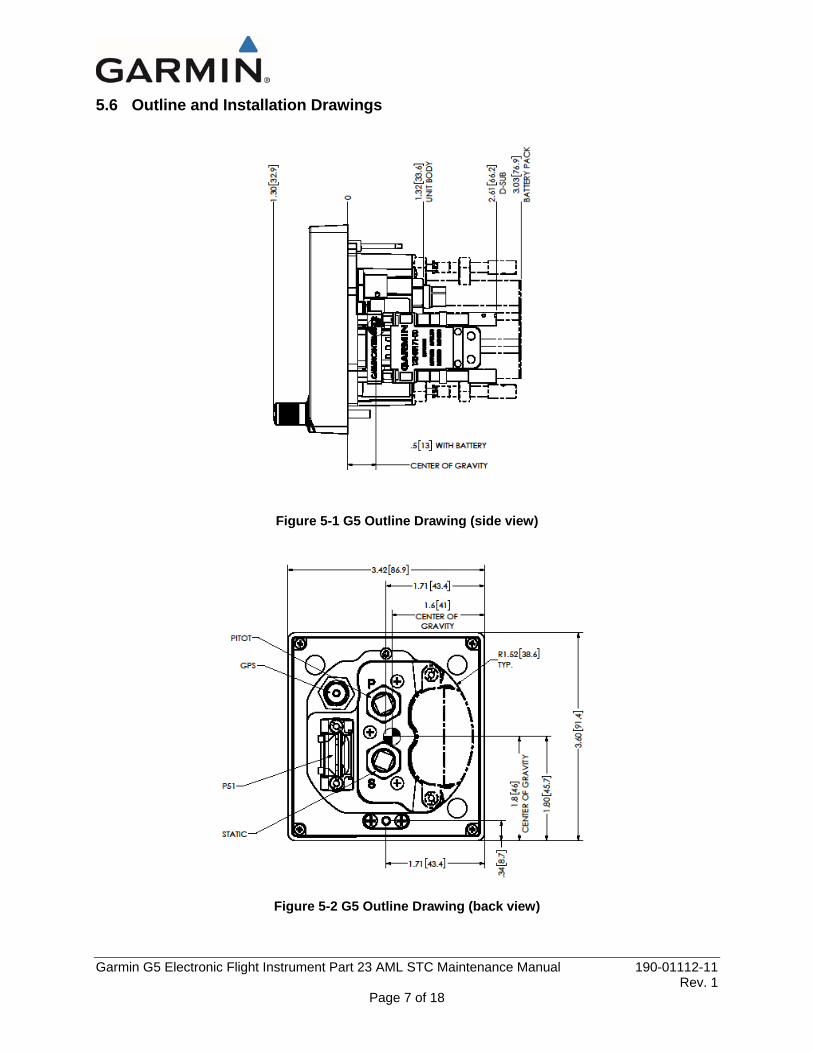
5.6 Outline and Installation Drawings
Figure 5-1 G5 Outline Drawing (side view)
Figure 5-2 G5 Outline Drawing (back view)

Garmin G5 Electronic Flight Instrument Part 23 AML STC Maintenance Manual 190-01112-11 Rev. 1
Page 8 of 18
Figure 5-3 G5 Exploded View
5.7 G5 Interconnect Drawings
Figure 5-4 J51 on the G5

Garmin G5 Electronic Flight Instrument Part 23 AML STC Maintenance Manual 190-01112-11 Rev. 1
Page 9 of 18
Figure 5-5 G5 with RS-232 Interface
Figure 5-6 G5 with External GPS Antenna

Garmin G5 Electronic Flight Instrument Part 23 AML STC Maintenance Manual 190-01112-11 Rev. 1
Page 10 of 18
6 EQUIPMENT REMOVAL & INSTALLATION This section describes how to remove and install the equipment associated with this STC.
6.1 G5 Unit
CAUTION: When removing and/or installing the G5, always ensure that aircraft power is off. Unplug any auxiliary power supplies.
Removal
1. Insert a hex drive tool through the access hole in the front cover of the G5 as shown in Figure 6-1 loosen the unit from the mounting ring.
Figure 6-1 G5 Hex Driver
2. Disconnect the pitot and static lines from the G5 unit.
3. Disconnect the electrical connector and GPS coaxial cable connector (if installed) from the G5 unit.
4. Remove the G5 unit. Reinstallation
1. Inspect the electrical and coaxial connectors and pins for signs of damage. Repair any damage.
2. Reconnect the electrical connector and GPS coaxial connector (if installed) to the G5 unit.

Garmin G5 Electronic Flight Instrument Part 23 AML STC Maintenance Manual 190-01112-11 Rev. 1
Page 11 of 18
3. Reconnect the pitot and static lines to the G5 unit. The ports are labeled on the unit using the abbreviations “P” and “S” respectively.
4. Insert the alignment pin located at the top of the unit into the mating hole in the mounting ring, pushing the unit flush with the instrument panel.
5. Insert a hex drive tool through the access hole in the front cover of the G5 as shown in Figure 6-1 and tighten the unit to the instrument panel using 10-12 in-lbs torque.
6. Proceed to Section 7 for configuration and testing. Note: If a replacement G5 unit is being installed in an instrument panel greater than 0.150 inch thick, the captive mounting screw must be replaced with a longer #6-32 hex socket head screw. To replace the captive mounting screw, remove the two #4-40 flat head Phillips mount plate screws, the G5 screw mount plate, and the captive screw as shown in Figure 6-2. Install a longer #6-32 hex socket head screw and reinstall the screw mount plate. Ensure correct orientation of the screw mount plate before applying 6-8 in-lb. of torque to the #4-40 mount plate screws.
Figure 6-2 G5 Captive Mounting Screw
6.2 G5 Battery
Removal
1. Loosen the G5 unit per Section 6.1. Do not remove the pitot and static lines or the electrical and GPS coaxial cable connectors from the G5 unit if access to the battery can be gained while these items remain connected.
2. Use a screwdriver to loosen the battery jackscrews on the back of the unit (reference Figure 5-3.) 3. Remove the battery from the G5 unit.
Reinstallation
1. Locate the battery on the back of the G5 unit. 2. Use a screwdriver to tighten the battery jackscrews to back of the G5 unit. 3. Reinstall the G5 unit per Section 6.1.

Garmin G5 Electronic Flight Instrument Part 23 AML STC Maintenance Manual 190-01112-11 Rev. 1
Page 12 of 18
6.3 G5 Mounting Ring Replacement
Removal
1. Loosen the G5 unit per Section 6.1. Do not remove the pitot and static lines or the electrical and GPS coaxial cable connectors from the G5 unit if access to the mounting ring can be gained while these items remain connected.
2. Remove the three #6-32 screws that secure the mounting ring to the instrument panel. 3. Remove the G5 mounting ring.
Reinstallation
1. Locate the new mounting ring, and secure to the instrument panel using the three #6-32 screws. 2. Evenly torque the screws to 10-12 in-lbs. 3. Reinstall the G5 unit per Section 6.1.
Figure 6-3 G5 Mounting Ring
6.4 GPS Antenna
Refer to the data which installed the GPS antenna for removal and installation of the GPS antenna.

Garmin G5 Electronic Flight Instrument Part 23 AML STC Maintenance Manual 190-01112-11 Rev. 1
Page 13 of 18
7 EQUIPMENT CONFIGURATION & TESTING This section contains instructions for configuration and checkout of the G5 Electronic Flight Instrument after reinstallation or replacement. The steps which are not applicable to a particular installation may be skipped.
The person performing these procedures must be familiar with the aircraft, have a working knowledge of typical avionics systems, and has experience using the test equipment defined in this section.
7.1 Recommended Test Equipment
The following test equipment is recommended to conduct the procedures in this section:
• Air data test set (pitot/static ramp tester)
• Digital Multi-Meter
• Ground power unit capable of supplying 14/28 Vdc power to the aircraft systems and avionics
• Digital Level or equivalent
NOTE All test equipment must have current calibration records.
7.2 Pitot Static System Leak Check
If the pitot and/or static system lines were removed from the G5 unit, perform a pitot static system leak check in accordance with the aircraft manufacturer’s approved data.
CAUTION To avoid damaging the G5 pressure sensors, both the pitot and static ports must be connected to the air data test set.
7.3 G5 Software
This section contains procedures for loading software to the G5 unit.
7.3.1 Loader Card Creation
To create a software loader card, follow the procedures outlined below.
1. To obtain the latest software version approved for this STC, visit www.Garmin.com and navigate to the Aviation Product/General Aviation/Indicators/G5 page. Do not download software from the Experimental Aircraft web page.
2. Download the self-extracting update file onto your hard drive.
3. Insert a FAT32-formatted microSD™ card with at least 20 MB of free space into your card reader.
4. Open the self-extracting update file and follow the instructions provided by the installer application. You will be prompted to specify the drive letter of the microSD card you wish to use for the update. When the transfer is complete, safely eject the microSD card.

Garmin G5 Electronic Flight Instrument Part 23 AML STC Maintenance Manual 190-01112-11 Rev. 1
Page 14 of 18
7.3.2 Software Loading Procedure
1. Power on the G5, then insert the software loader card created in Section 7.3.1 into the microSD™ card slot.
2. If the version of software on the card is newer than the version currently on the unit, a software update pop-up will appear on the screen. Select OK to begin the update.
3. The unit will reboot to the software update screen and the software update will begin automatically. This screen will show the progress of the software update.
4. Ensure power is not removed while the update is being performed.
5. The unit will reboot after the update is complete.
6. The new software version will be displayed while the unit powers on or in the configuration mode menu.
7.4 G5 Configuration Mode
To enter configuration mode, hold down the knob while powering on the G5. Configuration selections are made by rotating and pressing the knob on the face of the G5 as necessary to select the correct configurations.
7.4.1 Configuration Pages Summary
When in configuration mode, the G5 displays the following configurations pages:
• Device Information – used to display device specific information such as the software version and basic indicator configuration.
• Attitude – used to configure Indicator Type, Pitch Display preferences, and User Pitch offset. • Air Data – used to enable/ disable the G5 Air Data Sensors and configure the Vertical Speed rate. • Airspeed – allows for configuration of the reference speeds. • Flight Controls – used to configure the system for autopilot servos if installed. • Backlight – used to configure backlight configuration parameters. • Display – used to configure the display format of the G5. • Battery – used to set backup battery status and power off modes. • GPS – used to configure the internal GPS receiver. • Navigation – used to configure the display of navigation information • Units – This page is used to configure the units type to display altitude, airspeed, ground speed,
vertical speed and pressure displays. • RS-232 – used to configure the RS-232 input and output ports used of the G5. • ARINC 429 - used to configure the ARINC 429 input and output ports used of the G5. • Exit Configuration Mode – used to exit configuration mode.
7.4.2 G5 configuration
Before replacing a G5 unit, the technician should obtain the most current G5 configuration settings which are typically kept with the aircraft records. If the existing configuration setting record is not available, set the configuration to match the values and units indicated in the aircraft’s AFM or other operational information. If any changes are made to the configuration settings, record the new settings in Table 7-1 and keep in the aircraft records for future reference.

Garmin G5 Electronic Flight Instrument Part 23 AML STC Maintenance Manual 190-01112-11 Rev. 1
Page 15 of 18
Table 7-1: G5 Configuration Settings
Date: Aircraft Make/Model: Aircraft Reg #/Serial #:
G5 Part #: G5 Serial #: G5 software version:
CONFIGURATION PAGE CONFIGURATION OPTION CONFIGURATION SETTING
Device Information Installation Type Standalone Instrument Diagnostics/Data Log Enabled
Attitude Configuration Indicator Type Normal Pitch Display Normal
User Pitch Offset Disabled Air Data Air Data Sensors Enabled
Vertical Speed Indicator Airspeed
Note: Configure Units prior to
setting airspeeds
VNE VNO VSO VS1 VFE VA VX VY VG VR
VMC VYSE
Flight Controls Autopilot Servos None Backlight Current Mode Automatic
Default Mode Automatic Minimum Photocell Input Default
Minimum Display Brightness Default Maximum Photocell Input Default
Maximum Display Brightness Default Filter Time Constant Default
Display HSI Page Disabled Power Up Page PFD
Battery Show Status on PFD Always Automatic Power Off On Ground Only
GPS Internal GPS Receiver Enabled Navigation
Note: This configuration Page is only present when RS-232
Input Format is configured for MapMx
Navigation Data Disabled

Garmin G5 Electronic Flight Instrument Part 23 AML STC Maintenance Manual 190-01112-11 Rev. 1
Page 16 of 18
Date: Aircraft Make/Model: Aircraft Reg #/Serial #:
G5 Part #: G5 Serial #: G5 software version:
CONFIGURATION PAGE CONFIGURATION OPTION CONFIGURATION SETTING
Units Altitude Feet (ft) Distance Nautical (nm) or Statute (mi) Airspeed Nautical (kt) or Statute (mph)
Ground Speed Nautical (kt) or Statute (mph) Ground Track Magnetic Vertical Speed Feet/Minute
Pressure Inches (Hg) RS-232 Input Format None (Installations with an external
GPS antenna connected) MapMx (Installations connected to a
GTN or GNS for GPS position) Output Format None
ARINC 429 Output 1 None Output 2 None Input 1 None Input 2 None Input 3 None Input 4 None

Garmin G5 Electronic Flight Instrument Part 23 AML STC Maintenance Manual 190-01112-11 Rev. 1
Page 17 of 18
7.5 G5 Calibration Procedures
Table 7-2 describes the calibration procedures to be performed for the G5 unit after maintenance is performed.
Table 7-2: Calibration Procedure Summary
Calibration Procedure Procedure Name
Procedure Description Requirement
A Pitch/Roll Offset Compensation Level aircraft Procedure A is required if a new G5 unit is installed
C Air Data Static Pressure Calibration Altitude calibration
Procedure C is recommended if the G5 altimeter does not match primary altimeter
7.5.1 Calibration Procedure A: Pitch/Roll Offset Compensation
NOTE This procedure requires orienting the aircraft to normal flight attitude. This can be done by using jacks or placing wood blocks under the nose-wheel, for example. As another example, if the number of degrees ‘nose high’ the aircraft flies in straight and level cruise is known, a digital level can be used to orient the aircraft to normal flight attitude prior to the calibration.
NOTE The G5 must be leveled within 15.0° of the aircraft in-flight level cruise attitude. In-flight level cruise attitude is not necessarily the same as the level reference provided by the manufacturer (such as fuselage longerons).
1. Select the Attitude configuration page.
2. Select Calibrate Pitch/Roll.
3. Ensure that aircraft and the unit comply with all on-screen instructions then select Start.
4. A progress screen will then be displayed. There is a 30 second countdown timer for the procedure that resets when the aircraft moves.
5. When the calibration is complete, a successful status message will be displayed along with the new pitch and roll offsets.
7.5.2 Calibration Procedure C: Air Data Static Pressure Calibration
The Air Data configuration page has a selection for static pressure calibration. This procedure is used to perform an altimeter re-calibration. The altitude pressure sensor used in the G5 is very low drift and does not typically require re-calibration.
The static pressure calibration requires the use of a pressure control system (test set) with an altitude accuracy of at least ±5 ft. at sea level and ±20 ft. at 30,000 ft. It is necessary to re-calibrate to sea level (0 ft.), 10,000 ft., 20,000 ft., and optionally to 30,000 ft. The operator is allowed to finish the calibration at the end of the 20,000 ft. calibration if the aircraft operational ceiling is below 20,000 ft.

Garmin G5 Electronic Flight Instrument Part 23 AML STC Maintenance Manual 190-01112-11 Rev. 1
Page 18 of 18
CAUTION To avoid damaging the G5 pressure sensors, both the pitot and static ports must be connected to the test set.
1. Select the Air Data configuration page.
2. Select Calibrate Static Pressure.
3. Ensure all on-screen instructions have been complied with, then press Start.
4. At each calibration point the display will present a screen indicating the pressure altitude to set. Once the altitude is set, select Ready to calibrate this pressure.
5. During the calibration at each pressure, the pressure must be held constant for 30 seconds for the calibration step to be successful. The calibration may be cancelled at any point should the test setup require adjustment before repeating. A progress screen will be displayed showing the status of the test.
6. Select Done when the static pressure calibration is successfully completed.
7.6 Altimeter System Test
If the G5 unit is replaced, in aircraft that are IFR certified, perform an altimeter system test of the G5 in accordance with 14 CFR Part 43 Appendix E.
8 SYSTEM RETURN TO SERVICE PROCEDURE After all G5 configuration and testing is completed per Section 7, complete the following steps:
1. Apply power to the G5 unit.
2. If new software was updated, verify the correct software part number is displayed. To verify the latest software version approved for this STC, visit www.Garmin.com and navigate to the Aviation Product/General Aviation/Indicators/G5 page.
3. Verify the attitude is displayed and there are no invalid parameters (no red-X shown).


