33
190-01112-12 October 2017 Revision 3 Garmin G5 Electronic Flight Instrument Part 23 AML STC Pilot’s Guide

190-01112-12 October 2017 Revision 3
Garmin G5 Electronic Flight Instrument
Part 23 AML STC Pilot’s Guide
Garmin G5 Part 23 AML STC Pilot’s Guide 190-01112-12 Rev. 3
Page A
©2016-2017 Garmin International or its subsidiaries
All Rights Reserved
Except as expressly provided herein, no part of this manual may be reproduced, copied, transmitted, disseminated, downloaded or stored in any storage medium, for any purpose without the express prior written consent of Garmin. Garmin hereby grants permission to download a single copy of this manual and of any revision to this manual onto a hard drive or other electronic storage medium to be viewed and to print one copy of this manual or of any revision hereto, provided such electronic or printed copy of this manual or revision must contain the complete text of this copyright notice and provided further any unauthorized commercial distribution of this manual or any revision hereto is strictly prohibited.
Garmin® and flyGarmin® are registered trademarks of Garmin International or its subsidiaries. G5™ is a trademark of Garmin International or its subsidiaries. These trademarks may not be used without the express permission of Garmin.
Garmin International, Inc 1200 E. 151st Street Olathe, KS 66062 USA Telephone: 913-397-8200 Technical Support and Field Service Engineers: 888.606.5482 www.flyGarmin.com
Garmin (Europe) Ltd. Liberty House Bull Copse Road Hounsdown Business Park Southampton, SO40 9LR, UK Telephone: +44 (0) 23 8052 4000 Fax: +44 (0) 23 8052 4004
Garmin AT, Inc. 2345 Turner Rd. SE Salem, OR 97302 USA Telephone: 503.581.8101
Garmin G5 Part 23 AML STC Pilot’s Guide 190-01112-12 Rev. 3
Page B
RECORD OF REVISIONS
Revision Revision Date Description
1 7/21/16 Initial Release
2 4/19/17 Add G5 HSI
3 10/16/17 Add autopilot interface

Garmin G5 Part 23 AML STC Pilot’s Guide 190-01112-12 Rev. 3
Page i
INFORMATION SUBJECT TO EXPORT CONTROL LAWS
This document may contain information which is subject to the Export Administration Regulations (“EAR”) issued by the United States Department of Commerce (15 CFR, Chapter VII, Subchapter C) and which may not be exported, released, or disclosed to foreign nationals inside or outside of the United States without first obtaining an export license. A violation of the EAR may be subject to a penalty of up to 10 years imprisonment and a fine of up to $1,000,000 under Section 2410 of the Export Administration Act of 1979. Include this notice with any reproduced portion of this document.
NOTE: The display uses a lens with a special coating that may be sensitive to skin oils, waxes, and abrasive cleaners. CLEANERS CONTAINING AMMONIA WILL HARM THE ANTI-REFLECTIVE COATING. It is very important to clean the lens using a clean, lint-free cloth and a cleaner that is specified as safe for anti-reflective coatings. Avoid any chemical cleaners or solvents that can damage plastic components.
NOTE: Use of polarized eyewear may cause the display to appear dim or blank.
NOTE All images used in this document are current at the time of publication but are subject to change and may not be up to date.
Garmin G5 Part 23 AML STC Pilot’s Guide 190-01112-12 Rev. 3
Page ii
TABLE OF CONTENTS
SECTION ................................................................................................................................................ PAGE 1 SYSTEM DESCRIPTION ......................................................................................................................... 1
1.1 G5 Electronic Flight Instrument ........................................................................................................ 1 1.2 Bezel Overview ................................................................................................................................ 2 1.3 microSD™ Cards ............................................................................................................................... 3
2 OPERATION ............................................................................................................................................ 4 2.1 G5 Annunciations ............................................................................................................................. 4 2.2 G5 Attitude ....................................................................................................................................... 5 2.3 G5 Heading ...................................................................................................................................... 6 2.4 Backlight Intensity ............................................................................................................................ 7
3 ACCESSING FUNCTIONALITY .............................................................................................................. 8 3.1 Pages ............................................................................................................................................... 8 3.2 Menu ................................................................................................................................................ 8 3.3 PFD Page ......................................................................................................................................... 9 3.4 HSI Page ........................................................................................................................................ 19 3.5 Autopilot Operations with the G5 HSI ............................................................................................ 22 3.6 Navigation ...................................................................................................................................... 24
4 SYSTEM MESSAGES ........................................................................................................................... 28
Garmin G5 Part 23 AML STC Pilot’s Guide 190-01112-12 Rev. 3
Page 1 of 28
1 SYSTEM DESCRIPTION
1.1 G5 Electronic Flight Instrument
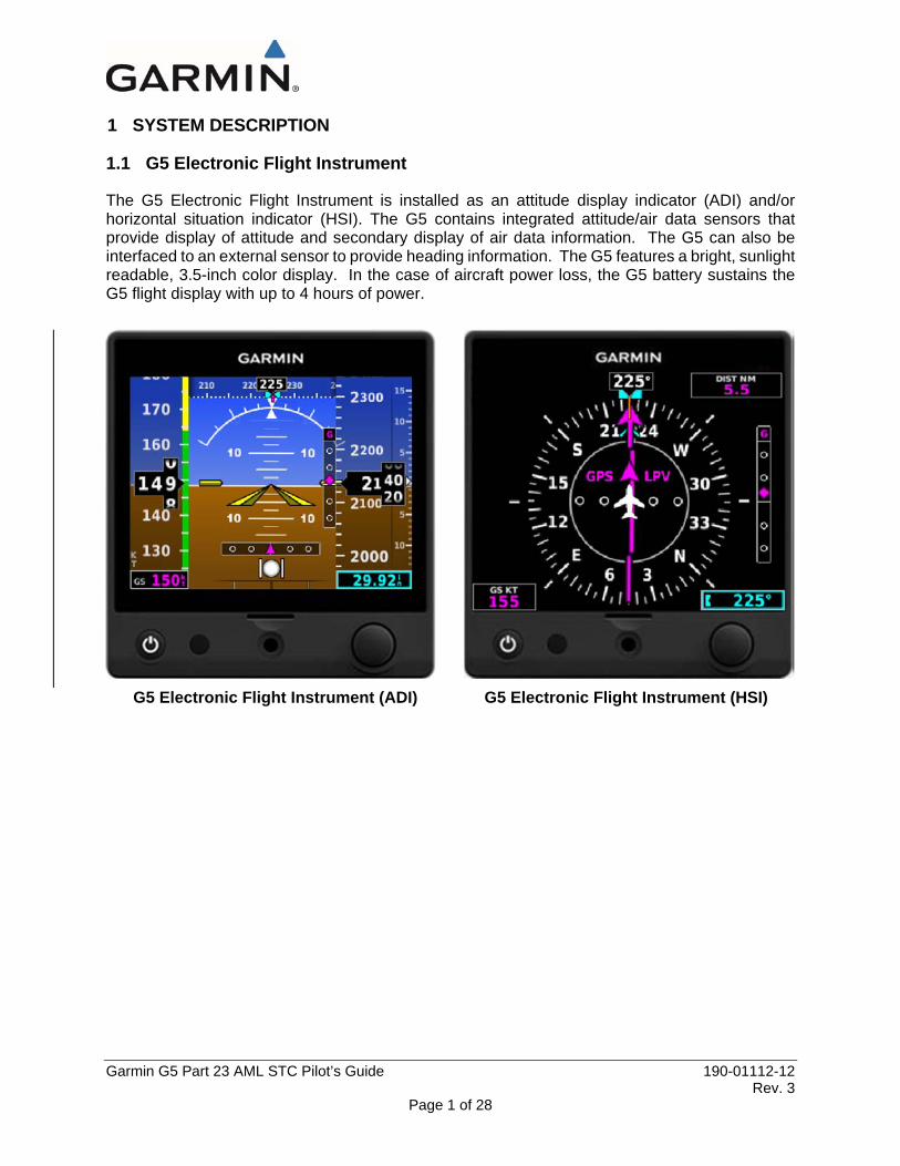
The G5 Electronic Flight Instrument is installed as an attitude display indicator (ADI) and/or horizontal situation indicator (HSI). The G5 contains integrated attitude/air data sensors that provide display of attitude and secondary display of air data information. The G5 can also be interfaced to an external sensor to provide heading information. The G5 features a bright, sunlight readable, 3.5-inch color display. In the case of aircraft power loss, the G5 battery sustains the G5 flight display with up to 4 hours of power.
G5 Electronic Flight Instrument (ADI) G5 Electronic Flight Instrument (HSI)

Garmin G5 Part 23 AML STC Pilot’s Guide 190-01112-12 Rev. 3
Page 2 of 28
1.2 Bezel Overview
Power On/Off microSD™ Backlight Card Slot Knob
Ambient Light Sensor
G5 Bezel Overview
Power Button
Press to turn unit ON. Press and hold for 5 seconds to turn unit OFF. Once on, press to adjust the backlight and display the battery status indicator.
microSD
Card Slot Insert microSD card to update software and log data.
Knob
Press
Press to access the Menu From the Menu, press to select the desired menu item. Press to accept the displayed value when editing numeric data or selecting from a list.
Turn
From the Main Menu, turn the Knob to move the cursor to the desired menu item. For the ADI, rotate to adjust the barometric setting. For the HSI, rotate to adjust the heading or track bug. Turn to select the desired value when editing numeric data or selecting from a list.
Garmin G5 Part 23 AML STC Pilot’s Guide 190-01112-12 Rev. 3
Page 3 of 28
1.3 MicroSD™ Cards
The G5 data card slot uses micro Secure Digital (SD) cards. The microSD™ card can be used for software updates and data logging. The maximum supported card size is 32GB.
Installing a microSD™ Card: 1) Insert the microSD™ card in the microSD™ card slot with the card contacts facing down
(the card should be flush with the face of the bezel).
2) To eject the card, gently press on the microSD™ card to release the spring latch.

Garmin G5 Part 23 AML STC Pilot’s Guide 190-01112-12 Rev. 3
Page 4 of 28
2 OPERATION
2.1 G5 Annunciations
When a G5 function fails, a large red ‘X’ is displayed over the instrument(s) or data experiencing the failure. Upon G5 power-up, certain instruments remain invalid as equipment begins to initialize. All instruments should be operational within one minute of power-up. If any instrument remains flagged and it is not likely an installation related problem, the G5 should be serviced by a Garmin-authorized repair facility.
G5 ADI Failure Indications
G5 HSI Failure Indications
Garmin G5 Part 23 AML STC Pilot’s Guide 190-01112-12 Rev. 3
Page 5 of 28
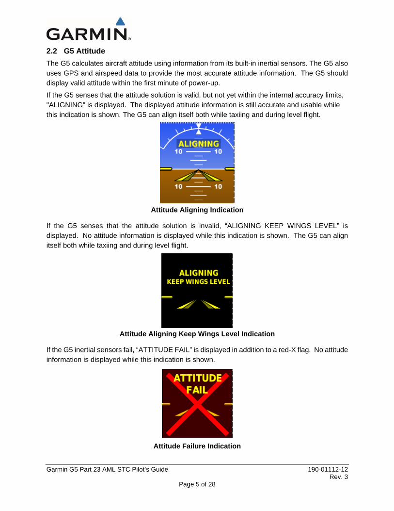
2.2 G5 Attitude The G5 calculates aircraft attitude using information from its built-in inertial sensors. The G5 also uses GPS and airspeed data to provide the most accurate attitude information. The G5 should display valid attitude within the first minute of power-up.
If the G5 senses that the attitude solution is valid, but not yet within the internal accuracy limits, "ALIGNING" is displayed. The displayed attitude information is still accurate and usable while this indication is shown. The G5 can align itself both while taxiing and during level flight.
Attitude Aligning Indication
If the G5 senses that the attitude solution is invalid, “ALIGNING KEEP WINGS LEVEL” is displayed. No attitude information is displayed while this indication is shown. The G5 can align itself both while taxiing and during level flight.
Attitude Aligning Keep Wings Level Indication
If the G5 inertial sensors fail, “ATTITUDE FAIL” is displayed in addition to a red-X flag. No attitude information is displayed while this indication is shown.
Attitude Failure Indication

Garmin G5 Part 23 AML STC Pilot’s Guide 190-01112-12 Rev. 3
Page 6 of 28
2.3 G5 Heading
The G5 can display magnetic heading information received from the GMU 11 magnetometer. If magnetic heading input data is not available, the G5 will display GPS-derived ground track and the heading field will have a red-X displayed.
Heading Fail (ADI) Heading Fail (HSI) If both magnetic heading and GPS are unavailable, the heading field will have a red-X displayed and the compass card will be removed from the HSI.
Heading/Track Fail (ADI) Heading/Track Fail (HSI)
The G5 corrects for shifts and variations in the Earth’s magnetic field by applying the Magnetic Field Variation Database. The Magnetic Field Variation Database is derived from the International Geomagnetic Reference Field (IGRF). The IGRF is a mathematical model that describes the Earth’s main magnetic field and its annual rate of change. The database is updated approximately every 5 years via a software update. Failure to update this database could lead to erroneous heading information being displayed to the pilot.
If the G5 senses that the magnetic heading measurement is valid but possibly outside of the internal accuracy limits, the numeric heading is displayed in yellow.
If the GAD 29B fails, VFR will be displayed in amber text and GPSS will be displayed in amber text, if GPSS mode is selected.
GAD29B Fail (Amber VFR) GAD29B Fail (Amber GPSS)
The heading and course datum will be unavailable to the autopilot and the autopilot may deviate from the intended path or may disconnect. When amber VFR is displayed, only lateral GPS course guidance may only be used. Deselect GPSS from the G5 menu and select a different autopilot mode.

Garmin G5 Part 23 AML STC Pilot’s Guide 190-01112-12 Rev. 3
Page 7 of 28
2.4 Backlight Intensity
When set to Auto, the backlight is automatically adjusted according to ambient light conditions. When set to Manual, the backlight level is set by the pilot.
Adjusting backlight intensity: 1) While the unit is turned on, press the Power Button.
2) Turn the Knob to adjust the backlight intensity.
3) Press the Knob to close the backlight page.
Setting the backlight intensity to automatic: 1) While the unit is turned on, press the Power Button.
2) Press the Power Button again to select Auto.
3) Press the Knob to close the backlight page.
Garmin G5 Part 23 AML STC Pilot’s Guide 190-01112-12 Rev. 3
Page 8 of 28
3 ACCESSING FUNCTIONALITY
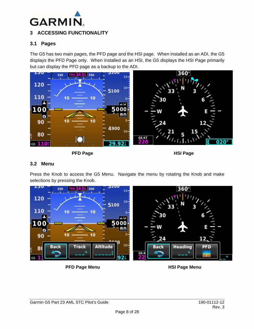
3.1 Pages
The G5 has two main pages, the PFD page and the HSI page. When installed as an ADI, the G5 displays the PFD Page only. When installed as an HSI, the G5 displays the HSI Page primarily but can display the PFD page as a backup to the ADI.
PFD Page HSI Page
3.2 Menu
Press the Knob to access the G5 Menu. Navigate the menu by rotating the Knob and make selections by pressing the Knob.
PFD Page Menu HSI Page Menu

Garmin G5 Part 23 AML STC Pilot’s Guide 190-01112-12 Rev. 3
Page 9 of 28
3.3 PFD Page
The G5 PFD Page displays a horizon, airspeed, attitude, altitude, and vertical speed, as well as heading and course deviation information if combined with a G5 HSI.
The following flight instruments and supplemental flight data are displayed on the PFD Page:
G5 PFD Flight Instruments
Airspeed Indicator Vertical Speed Indicator
Attitude Indicator Current Altitude
Pitch Scale VNAV Indicator or Vertical Deviation Indicator
Current Airspeed Altimeter
Aircraft Symbol Selected Altitude
Course Deviation Indicator Navigation Course
Slip/Skid Indicator Current Heading or Ground Track
Ground Speed (GS) Ground Track
Altimeter Barometer Setting Selected Heading or Ground Track
Turn Rate Indicator Vspeed Reference
Selected Altitude Bug Battery Status Indicator
1
2
3
4
5
7
8 9
10
13
12
1819
11
15
16
21 22
6
14
7 18
17
8
9
10
11
19
20
21
22
1
2
3
4
5
12
13
14
15
16
6 17
20
Garmin G5 Part 23 AML STC Pilot’s Guide 190-01112-12 Rev. 3
Page 10 of 28
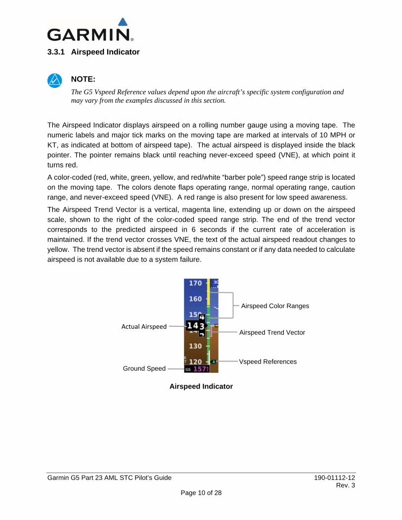
3.3.1 Airspeed Indicator
NOTE: The G5 Vspeed Reference values depend upon the aircraft’s specific system configuration and may vary from the examples discussed in this section.
The Airspeed Indicator displays airspeed on a rolling number gauge using a moving tape. The numeric labels and major tick marks on the moving tape are marked at intervals of 10 MPH or KT, as indicated at bottom of airspeed tape). The actual airspeed is displayed inside the black pointer. The pointer remains black until reaching never-exceed speed (VNE), at which point it turns red.
A color-coded (red, white, green, yellow, and red/white “barber pole”) speed range strip is located on the moving tape. The colors denote flaps operating range, normal operating range, caution range, and never-exceed speed (VNE). A red range is also present for low speed awareness.
The Airspeed Trend Vector is a vertical, magenta line, extending up or down on the airspeed scale, shown to the right of the color-coded speed range strip. The end of the trend vector corresponds to the predicted airspeed in 6 seconds if the current rate of acceleration is maintained. If the trend vector crosses VNE, the text of the actual airspeed readout changes to yellow. The trend vector is absent if the speed remains constant or if any data needed to calculate airspeed is not available due to a system failure.
Airspeed Indicator
Vspeed References Ground Speed
Airspeed Trend Vector
Airspeed Color Ranges
Actual Airspeed
Garmin G5 Part 23 AML STC Pilot’s Guide 190-01112-12 Rev. 3
Page 11 of 28
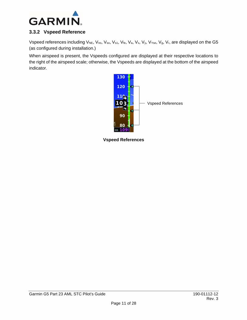
3.3.2 Vspeed Reference
Vspeed references including VNE, Vno, Vso, Vs1, Vfe, Va, Vx, Vy, VYse, Vg, Vr, are displayed on the G5 (as configured during installation.)
When airspeed is present, the Vspeeds configured are displayed at their respective locations to the right of the airspeed scale; otherwise, the Vspeeds are displayed at the bottom of the airspeed indicator.
Vspeed References
Vspeed References
Garmin G5 Part 23 AML STC Pilot’s Guide 190-01112-12 Rev. 3
Page 12 of 28
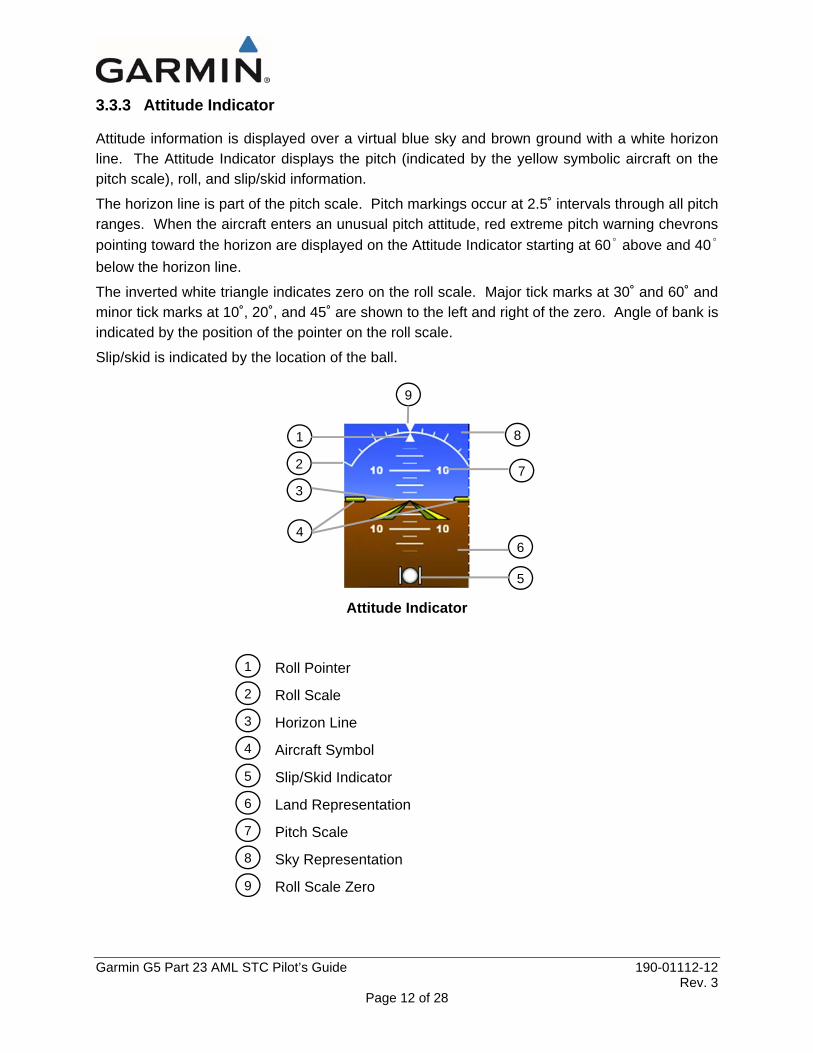
3.3.3 Attitude Indicator
Attitude information is displayed over a virtual blue sky and brown ground with a white horizon line. The Attitude Indicator displays the pitch (indicated by the yellow symbolic aircraft on the pitch scale), roll, and slip/skid information.
The horizon line is part of the pitch scale. Pitch markings occur at 2.5˚ intervals through all pitch ranges. When the aircraft enters an unusual pitch attitude, red extreme pitch warning chevrons pointing toward the horizon are displayed on the Attitude Indicator starting at 60˚ above and 40˚ below the horizon line.
The inverted white triangle indicates zero on the roll scale. Major tick marks at 30˚ and 60˚ and minor tick marks at 10˚, 20˚, and 45˚ are shown to the left and right of the zero. Angle of bank is indicated by the position of the pointer on the roll scale.
Slip/skid is indicated by the location of the ball.
Attitude Indicator
Roll Pointer
Roll Scale
Horizon Line
Aircraft Symbol
Slip/Skid Indicator
Land Representation
Pitch Scale
Sky Representation
Roll Scale Zero
1
2
3
4
5
6
7
8
9
1
2
3
4
5
6
7
8
9

Garmin G5 Part 23 AML STC Pilot’s Guide 190-01112-12 Rev. 3
Page 13 of 28
3.3.4 Altimeter
The Altimeter displays 400 feet of barometric altitude values at a time on a rolling number gauge using a moving tape. Numeric labels and major tick marks are shown at intervals of 100 feet. Minor tick marks are at intervals of 20 feet. The current altitude is displayed in the black pointer.
The Selected Altitude is displayed above the Altimeter in the box indicated by a selection bug symbol. A bug corresponding to this altitude is shown on the tape. If the Selected Altitude exceeds the range shown on the tape, the bug appears at the corresponding edge of the tape.
Setting the selected altitude: 1) Press the Knob to display the Menu.
2) Select Altitude and use the Knob to change the Selected Altitude.
Syncing to the current altitude: 1) Press the Knob to display the Menu.
2) Select Altitude and press and hold the Knob to sync the Selected Altitude to the current altitude.
Altimeter
3.3.5 Barometric Pressure
The barometric pressure setting is displayed below the Altimeter in inches of mercury (in Hg).
Selecting the altimeter barometric pressure setting: Turn the Knob to set the barometric pressure.
Selected Altitude
Selected Altitude Bug
Barometric Setting

Garmin G5 Part 23 AML STC Pilot’s Guide 190-01112-12 Rev. 3
Page 14 of 28
3.3.6 Altitude Alerting
The Altitude Alerting function provides the pilot with a visual alert when approaching the Selected Altitude. Whenever the Selected Altitude is changed, the Altitude Alerter is reset. The following will occur when approaching the Selected Altitude:
• Passing within 1000 feet of the Selected Altitude, the Selected Altitude (shown above the Altimeter) flashes for 5 seconds.
• When the aircraft passes within 200 ft of the Selected Altitude, the Selected Altitude flashes for 5 seconds to indicate that the aircraft is approaching the selected altitude.
• After reaching the Selected Altitude, if the pilot flies outside the deviation band (±200 Feet of the Selected Altitude), the Selected Altitude changes to yellow text on a black background, flashes for 5 seconds.
Deviation of ±200 ft
Altitude Alerting Visual Annunciation
Garmin G5 Part 23 AML STC Pilot’s Guide 190-01112-12 Rev. 3
Page 15 of 28
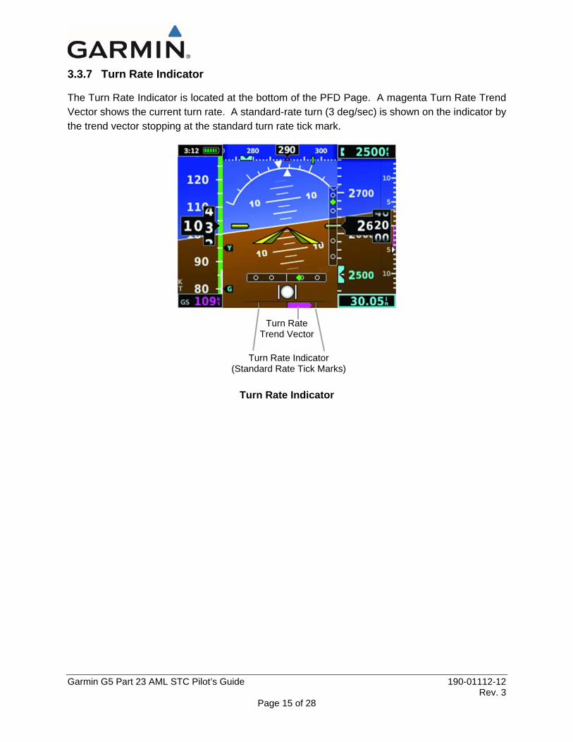
3.3.7 Turn Rate Indicator
The Turn Rate Indicator is located at the bottom of the PFD Page. A magenta Turn Rate Trend Vector shows the current turn rate. A standard-rate turn (3 deg/sec) is shown on the indicator by the trend vector stopping at the standard turn rate tick mark.
Turn Rate Indicator
Turn Rate Trend Vector
Turn Rate Indicator (Standard Rate Tick Marks)

Garmin G5 Part 23 AML STC Pilot’s Guide 190-01112-12 Rev. 3
Page 16 of 28
3.3.8 Heading/Ground Track
A Heading/Ground Track Tape is displayed at the top of the PFD Page and displays numeric labels every 10°. Major tick marks are at 5° intervals and minor tick marks at 1° intervals. Heading is displayed if a G5 HSI is installed and magnetometer data is available; otherwise, Track is displayed. The current track is represented by a magenta triangle. The Heading/Ground Track Tape also displays the navigation course.
When displaying Selected Heading, a light blue bug on the tape corresponds to the selected heading. When displaying Ground Track, a magenta bug is displayed on the tape.
Adjusting the selected heading or ground track: 1) Press the Knob to display the Menu.
2) Select Heading or Track and use the Knob to change the selected heading or track.
Syncing to the current heading or ground track: 1) Press the Knob to display the Menu.
2) Select Heading or Track and press and hold the Knob to sync the selected heading or ground track to the current heading or ground track.
Selected Heading
Selected Heading
Bug
Current Heading
Current Ground Track

Garmin G5 Part 23 AML STC Pilot’s Guide 190-01112-12 Rev. 3
Page 17 of 28
Selected Ground Track
3.3.9 Vertical Speed Indicator (VSI)
The Vertical Speed Indicator displays the aircraft vertical speed using a non-moving tape to the right of the altimeter. The current vertical speed is displayed using a white arrow along the tape.
Vertical Speed Indicator
Current Ground Track
Selected Ground
Track Bug
Current Vertical Speed
Garmin G5 Part 23 AML STC Pilot’s Guide 190-01112-12 Rev. 3
Page 18 of 28
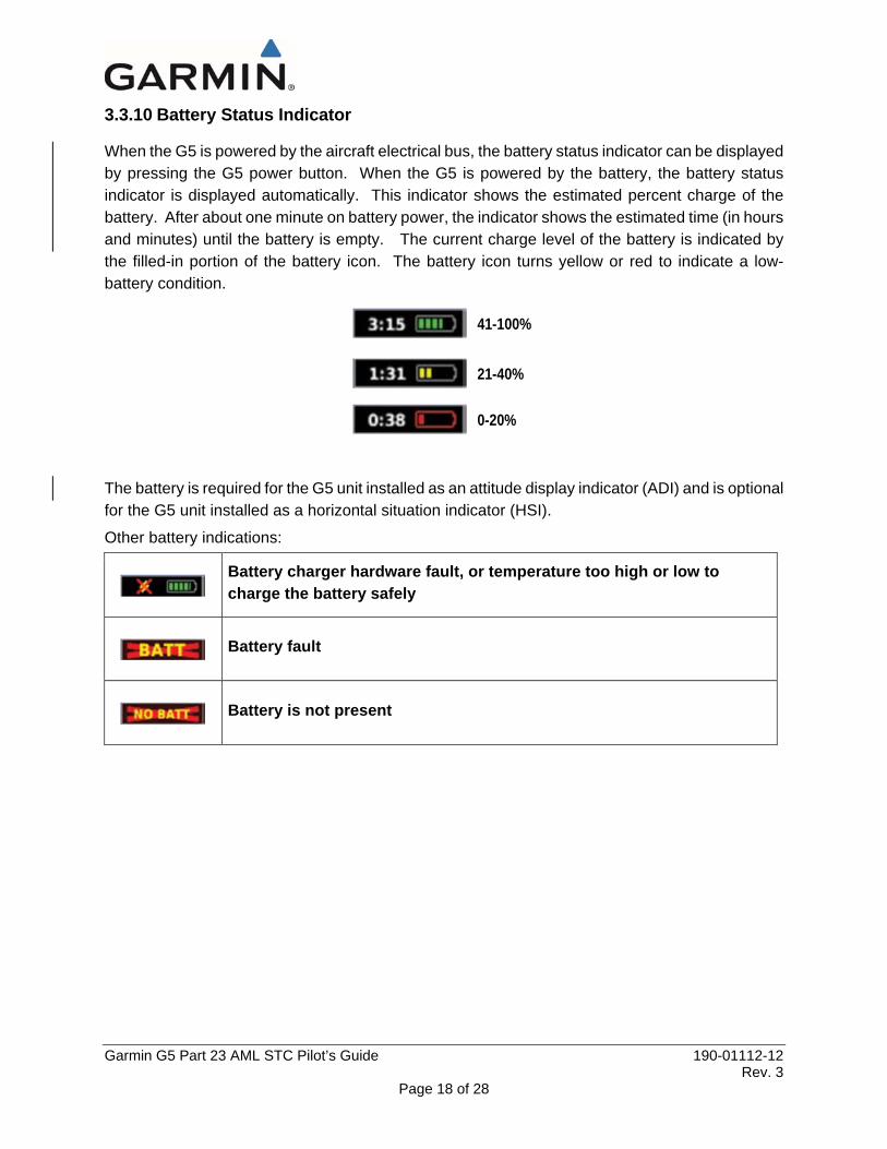
3.3.10 Battery Status Indicator
When the G5 is powered by the aircraft electrical bus, the battery status indicator can be displayed by pressing the G5 power button. When the G5 is powered by the battery, the battery status indicator is displayed automatically. This indicator shows the estimated percent charge of the battery. After about one minute on battery power, the indicator shows the estimated time (in hours and minutes) until the battery is empty. The current charge level of the battery is indicated by the filled-in portion of the battery icon. The battery icon turns yellow or red to indicate a low-battery condition.
41-100%
21-40%
0-20%
The battery is required for the G5 unit installed as an attitude display indicator (ADI) and is optional for the G5 unit installed as a horizontal situation indicator (HSI).
Other battery indications:
Battery charger hardware fault, or temperature too high or low to charge the battery safely
Battery fault
Battery is not present
Garmin G5 Part 23 AML STC Pilot’s Guide 190-01112-12 Rev. 3
Page 19 of 28
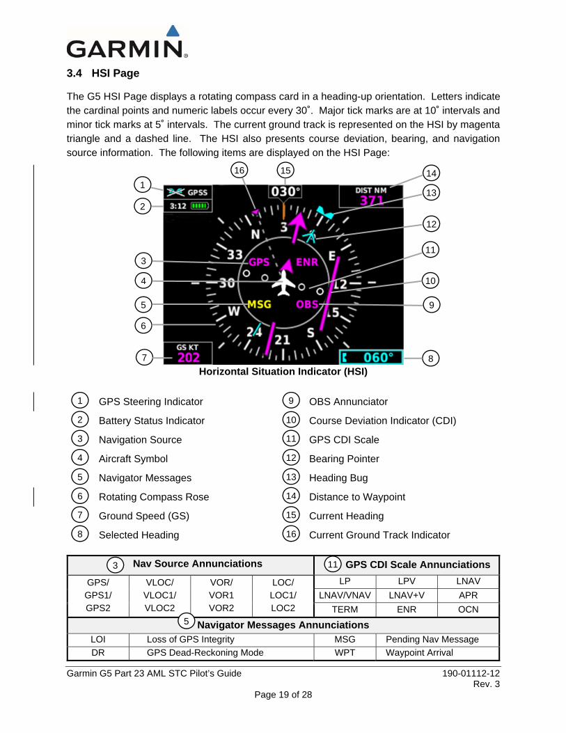
3.4 HSI Page
The G5 HSI Page displays a rotating compass card in a heading-up orientation. Letters indicate the cardinal points and numeric labels occur every 30˚. Major tick marks are at 10˚ intervals and minor tick marks at 5˚ intervals. The current ground track is represented on the HSI by magenta triangle and a dashed line. The HSI also presents course deviation, bearing, and navigation source information. The following items are displayed on the HSI Page:
Horizontal Situation Indicator (HSI)
GPS Steering Indicator OBS Annunciator
Battery Status Indicator Course Deviation Indicator (CDI)
Navigation Source GPS CDI Scale
Aircraft Symbol Bearing Pointer
Navigator Messages Heading Bug
Rotating Compass Rose Distance to Waypoint
Ground Speed (GS) Current Heading
Selected Heading Current Ground Track Indicator
Nav Source Annunciations GPS CDI Scale Annunciations GPS/ GPS1/ GPS2
VLOC/ VLOC1/ VLOC2
VOR/ VOR1 VOR2
LOC/ LOC1/ LOC2
LP LPV LNAV LNAV/VNAV LNAV+V APR
TERM ENR OCN
Navigator Messages Annunciations LOI Loss of GPS Integrity MSG Pending Nav Message DR GPS Dead-Reckoning Mode WPT Waypoint Arrival
7
6
5
4
3
2
8
1 13
11
10
9
3 11
5
16 15
12
5
1
2
3
4
9
10
11
12
13
7
6 14
15
8 16
14
Garmin G5 Part 23 AML STC Pilot’s Guide 190-01112-12 Rev. 3
Page 20 of 28
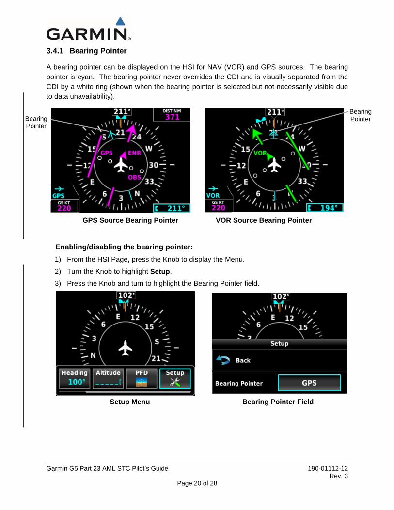
3.4.1 Bearing Pointer
A bearing pointer can be displayed on the HSI for NAV (VOR) and GPS sources. The bearing pointer is cyan. The bearing pointer never overrides the CDI and is visually separated from the CDI by a white ring (shown when the bearing pointer is selected but not necessarily visible due to data unavailability).
GPS Source Bearing Pointer VOR Source Bearing Pointer
Enabling/disabling the bearing pointer: 1) From the HSI Page, press the Knob to display the Menu.
2) Turn the Knob to highlight Setup.
3) Press the Knob and turn to highlight the Bearing Pointer field.
Setup Menu Bearing Pointer Field
Bearing Pointer Bearing
Pointer
Garmin G5 Part 23 AML STC Pilot’s Guide 190-01112-12 Rev. 3
Page 21 of 28
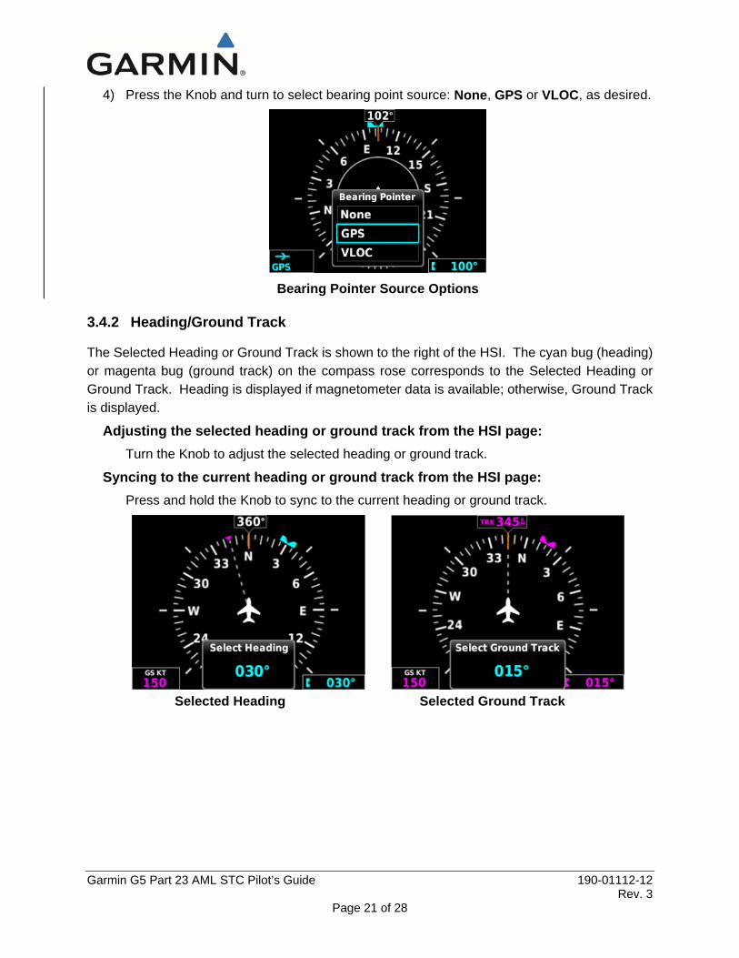
4) Press the Knob and turn to select bearing point source: None, GPS or VLOC, as desired.
Bearing Pointer Source Options
3.4.2 Heading/Ground Track
The Selected Heading or Ground Track is shown to the right of the HSI. The cyan bug (heading) or magenta bug (ground track) on the compass rose corresponds to the Selected Heading or Ground Track. Heading is displayed if magnetometer data is available; otherwise, Ground Track is displayed.
Adjusting the selected heading or ground track from the HSI page: Turn the Knob to adjust the selected heading or ground track.
Syncing to the current heading or ground track from the HSI page: Press and hold the Knob to sync to the current heading or ground track.
Selected Heading Selected Ground Track

Garmin G5 Part 23 AML STC Pilot’s Guide 190-01112-12 Rev. 3
Page 22 of 28
3.4.3 GPS Steering
The G5 can provide GPS steering input to an autopilot. When GPSS is selected, the heading bug is hollow and “GPSS” is shown in the upper left hand corner of the display.
G5 ADI with GPSS G5 HSI with GPSS
Enabling/disabling GPSS: 1) Press the Knob to display the Menu.
2) Turn the Knob to highlight GPSS.
3) Press the Knob to enable or disable GPSS.
3.5 Autopilot Operations with the G5 HSI When interfaced to an autopilot, the G5 may provide the following functions:
• Course / NAV Selection coupling to the autopilot. • Heading Bug coupling capability to the autopilot. • Roll Steering (GPSS) emulated via heading mode.
• OR • Roll Steering capable autopilot (GPSS menu function for emulation not applicable).
3.5.1 Course / NAV Selection Coupling to the Autopilot When operating the autopilot in NAV mode, the deviation information from the installed navigation sources (i.e. GPS or NAV) is switched via the navigation source. The NAV source displayed on the HSI is the NAV source the autopilot is following. Many autopilots also use the course datum to determine the best intercept angles when operating in NAV mode.

Garmin G5 Part 23 AML STC Pilot’s Guide 190-01112-12 Rev. 3
Page 23 of 28
3.5.2 Heading Bug Coupling Capability to the Autopilot When operating the autopilot in HDG mode, the difference between the HDG bug location on the HSI and the actual aircraft heading creates an error signal which the autopilot will minimize by turning in the direction of the bug. If the bug is turned more than 180 degrees, the autopilot may turn the airplane in the opposite direction of the desired turn.
3.5.3 Roll Steering (GPSS) Emulated via HDG Mode For autopilots that do not support digital GPSS signals, GPSS functionality may be emulated by operating the autopilot in HDG mode and selecting GPSS from the G5 menu. If the autopilot is already designed to receive roll steering information, the data is transmitted digitally from the navigator to the autopilot.
When GPSS is selected on the G5 menu, the heading bug on the HSI changes to a hollow outline and a crossed-out heading bug appears on the G5 HSI display indicating that the autopilot is not coupled to the heading bug. The bug is still controllable and may still be used for reference.
When GPSS is selected on the G5, GPSS turn commands are converted into a heading error signal to the autopilot. When the autopilot is operated in HDG mode, the autopilot will fly the turn commands from the GPS navigator. If the GPSS data is invalid (for example, if there is no active GPS leg) or the selected HSI source on the G5 HSI is not GPS, the annunciated GPSS text will be yellow and a zero turn command will be sent to the autopilot.

Garmin G5 Part 23 AML STC Pilot’s Guide 190-01112-12 Rev. 3
Page 24 of 28
3.6 Navigation
The G5 will only display data from the #1 navigation source. If the navigation source is a GNS/GTN unit, both GPS and VLOC data can be displayed.
3.6.1 Course Deviation Indicator (CDI)
The PFD Page displays the Course Deviation Indicator (CDI) above the slip/skid indicator. The HSI contains a Course Deviation Indicator (CDI) with a Course Pointer. The course pointer (GPS or VLOC) points in the direction of the selected course.
The Course Deviation Indicator (CDI) moves left or right along a lateral deviation scale to display aircraft position relative to the course. If the course deviation data is not valid, the CDI is not displayed.
The CDI is capable of displaying two sources of navigation: GPS or NAV (VOR, localizer). Color indicates the current navigation source: magenta (for GPS) or green (for VOR and LOC). The full-scale limits for the CDI are defined by a GPS-derived distance when coupled to GPS. When coupled to a VOR or localizer (LOC), the CDI has the same angular limits as a mechanical CDI.
Changing the navigation source (GPS, VOR, LOC, or VLOC): Use the #1 external navigator to toggle between GPS and VOR/LOC source types.
Course Deviation Indicator (PFD Page)
Course Deviation Indicator (HSI Page)
Course Deviation Indicator
Course Deviation Indicator
Garmin G5 Part 23 AML STC Pilot’s Guide 190-01112-12 Rev. 3
Page 25 of 28
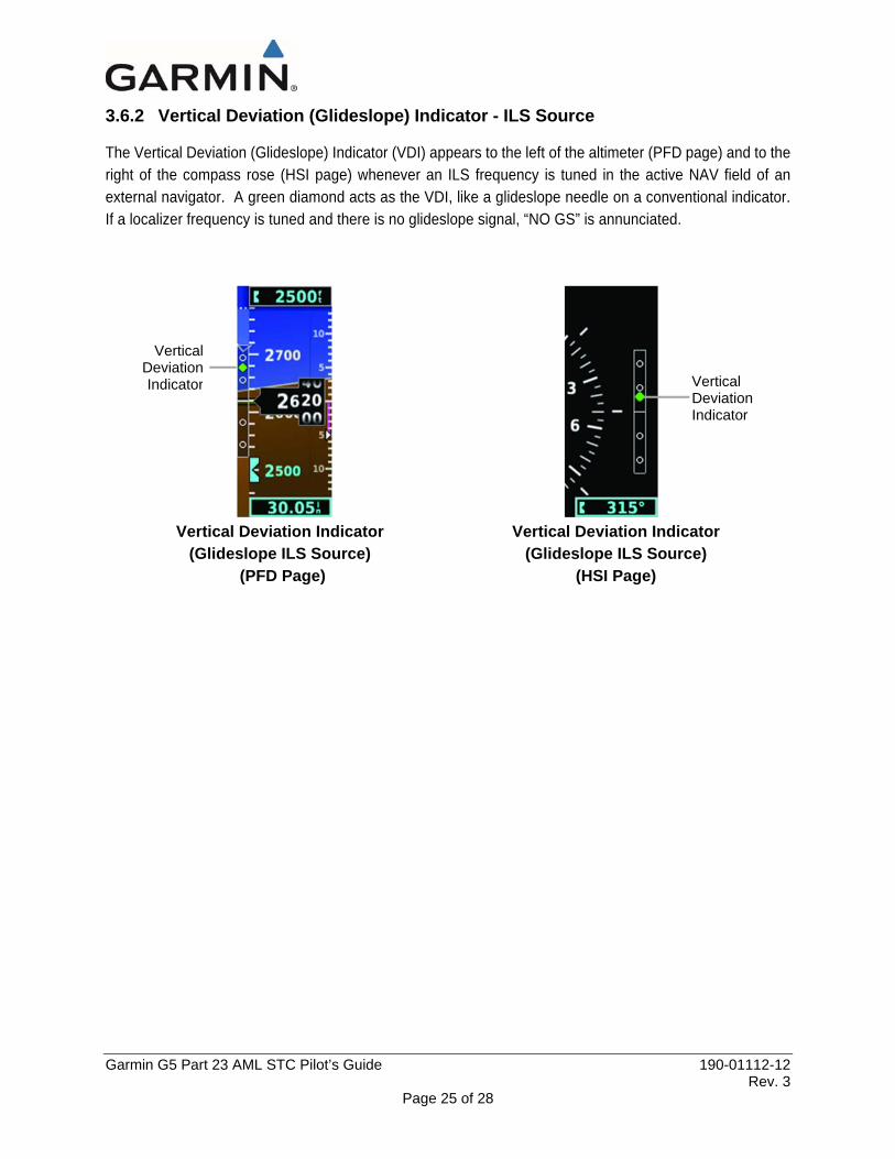
3.6.2 Vertical Deviation (Glideslope) Indicator - ILS Source
The Vertical Deviation (Glideslope) Indicator (VDI) appears to the left of the altimeter (PFD page) and to the right of the compass rose (HSI page) whenever an ILS frequency is tuned in the active NAV field of an external navigator. A green diamond acts as the VDI, like a glideslope needle on a conventional indicator. If a localizer frequency is tuned and there is no glideslope signal, “NO GS” is annunciated.
Vertical Deviation Indicator Vertical Deviation Indicator (Glideslope ILS Source) (Glideslope ILS Source)
(PFD Page) (HSI Page)
Vertical Deviation Indicator Vertical
Deviation Indicator
Garmin G5 Part 23 AML STC Pilot’s Guide 190-01112-12 Rev. 3
Page 26 of 28
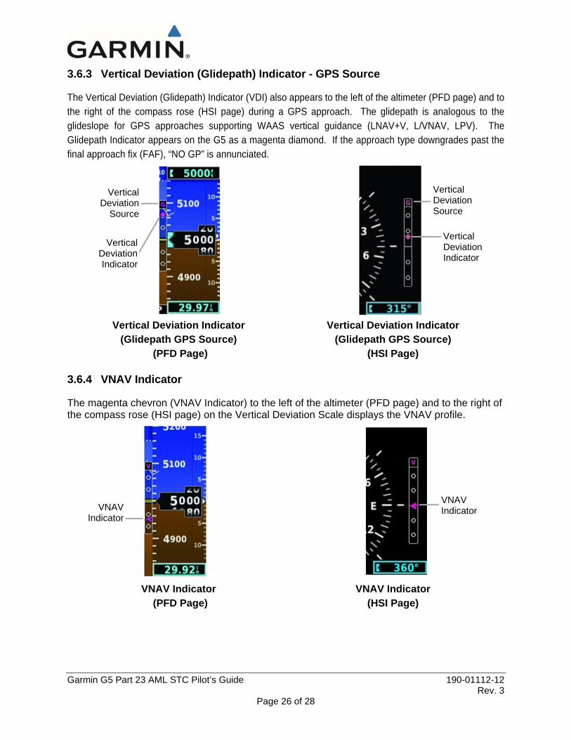
3.6.3 Vertical Deviation (Glidepath) Indicator - GPS Source
The Vertical Deviation (Glidepath) Indicator (VDI) also appears to the left of the altimeter (PFD page) and to the right of the compass rose (HSI page) during a GPS approach. The glidepath is analogous to the glideslope for GPS approaches supporting WAAS vertical guidance (LNAV+V, L/VNAV, LPV). The Glidepath Indicator appears on the G5 as a magenta diamond. If the approach type downgrades past the final approach fix (FAF), “NO GP” is annunciated.
Vertical Deviation Indicator Vertical Deviation Indicator (Glidepath GPS Source) (Glidepath GPS Source)
(PFD Page) (HSI Page)
3.6.4 VNAV Indicator
The magenta chevron (VNAV Indicator) to the left of the altimeter (PFD page) and to the right of the compass rose (HSI page) on the Vertical Deviation Scale displays the VNAV profile.
VNAV Indicator VNAV Indicator (PFD Page) (HSI Page)
VerticalDeviationIndicator
Vertical Deviation
Source
VNAV Indicator
Vertical Deviation Indicator
Vertical Deviation Source
VNAV Indicator
Garmin G5 Part 23 AML STC Pilot’s Guide 190-01112-12 Rev. 3
Page 27 of 28
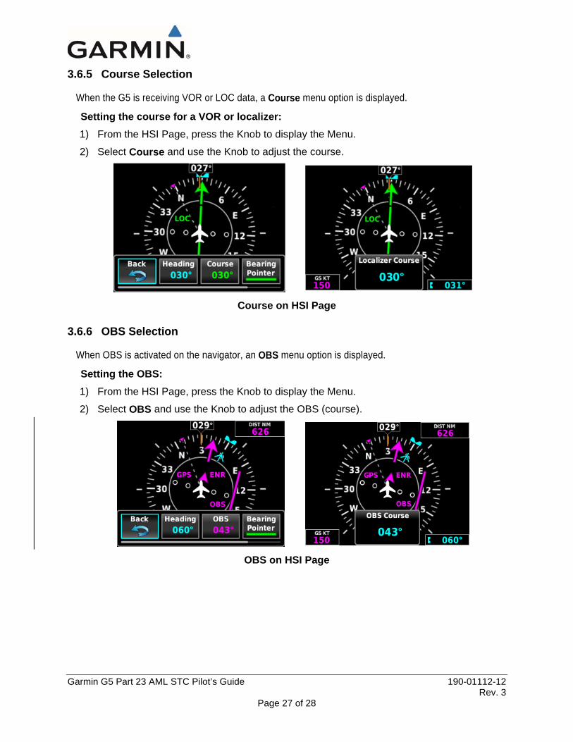
3.6.5 Course Selection
When the G5 is receiving VOR or LOC data, a Course menu option is displayed.
Setting the course for a VOR or localizer: 1) From the HSI Page, press the Knob to display the Menu.
2) Select Course and use the Knob to adjust the course.
Course on HSI Page
3.6.6 OBS Selection
When OBS is activated on the navigator, an OBS menu option is displayed.
Setting the OBS: 1) From the HSI Page, press the Knob to display the Menu.
2) Select OBS and use the Knob to adjust the OBS (course).
OBS on HSI Page
Garmin G5 Part 23 AML STC Pilot’s Guide 190-01112-12 Rev. 3
Page 28 of 28
4 SYSTEM MESSAGES The following table shows G5 system messages that may appear along the bottom of the display. These messages remain while the condition persists or until cleared by pressing the knob.
Message Meaning
External Power Lost Aircraft power has been removed from the G5
Critical battery fault! Powering off…
Battery has critical fault condition and the unit is about to power off to avoid damage to the battery.
Battery fault Battery has a fault condition - contact Garmin if it persists.
Battery charger fault Battery charger has a fault condition - contact Garmin if it persists.
Low battery Battery charge level is low
Hardware fault Unit has a hardware fault - contact Garmin for service
Power supply fault Unit power supply fault detected - contact Garmin for service if it persists
Unit temperature limit exceeded
Unit is too hot or too cold
Network address conflict
Another G5 with the same address is detected on the network (most commonly a wiring error on one of the units)
Communication error General communication error (most commonly appears in conjunction with Network Address Conflict message)
Factory calibration data invalid
Unit calibration data not valid - return to Garmin
Magnetic field model database out of date
Internal magnetic field database is out of date - software update required
Using external GPS data
GPS data from another network LRU is being used. The unit's internal GPS receiver is enabled, but unable to establish a GPS fix


