OEM Data Centers Project Services Carrier Networks Private Networks Corning Cable Systems FiberWay ™ Fiber Optic Cables for Duct and Buried Applications Issue 2 Maulwurf. Michael P. Giordano. November 2000 Übersetzung fehlt!!!!
Transcript
OEM Data Centers Project ServicesCarrier Networks Private Networks
CorningCable Systems
FiberWay™Fiber Optic Cables for Duct and Buried ApplicationsIssue 2
Maulwurf. Michael P. Giordano. November 2000
Übersetzungfehlt!!!!
2
FiberWayRibbon Cables
FiberWay Ribbon designs404
56
810
Introduction
Corning: an experienced and reliable partner for youThe Customer is our Focal PointGlobal Cable and Hardware BusinessEverything from a Single SourceOptical Fiber
FiberWayFiber Optic Duct and Buried Cables
Fiber optic duct and buried cables:Security with FiberWayIdentification of fiber optic ductand buried cablesFiberWay – two product familiesWe can do itFiberWay –stranded and loose tube designFiber optic duct cableFiber optic buried cable
14
17
181920
2131
Corning Cable Systems 3
49
5053
Additional Information
Corning AccessoriesSolutions for all fiber networks
TrainingExpertise for your personnel
Cable Laying, PackagingMethods of cable layingTypes of drum lagging
AppendixTechnical TermyCatalogs available in our Product RangeSales ContactsCustomer Service
Type Codes and Color Codes for Fiber Optic Cables see last page.
FutureLinkFiber Optic Multi Purposeand Campus Cables
Fiber optic Multi-Purpose and Campus CablesCampus Backbone CableMulti-Purpose Cable
58
59
6066
67717273
CORNING CABLE SYSTEMS
4
Corning: an experienced and reliable partner for you
>
In 2000, Corning consolidated its entire cable, hardware, equipment and services business into Corning Cable Systems. Corning Cable Systems comprises the formerSiecor Corporation, BICC’s communication cables business (Corning Cables), Siemens’former Communication Cables division and RXS Kabelgarnituren.
With over 150 years of experience in the world of telecommunications,we are an expe-rienced partner you can trust to bring cost-effective solutions to your communicationrequirements. In the field of fiber optic cable technology,Corning was one of the original pioneers with expertise second to none.
The first milestone was set by Corning in 1970 with the invention of the low loss glassfiber as an optical transmission medium. As early as 1974,when fiber optic technologywas still in its infancy, Corning Cable Systems was working with Europe’s leading Public Telecommunications companies in developing trial fiber optic cable routes. In the late ‘70s came the initial projects in the USA which marked the start of a globalbusiness embracing a large number of demanding customer projects.
As a leading cable system provider, we can supply our customers not only with individ-ual products but also complete cabling solutions from a single source. To complementour cable developments and the increasing complexity of optical and high performancecopper cable networks, we have built up an extensive range of interconnection anddistribution hardware.
The Customer is our Focal Point>
Corning Cable Systems 5
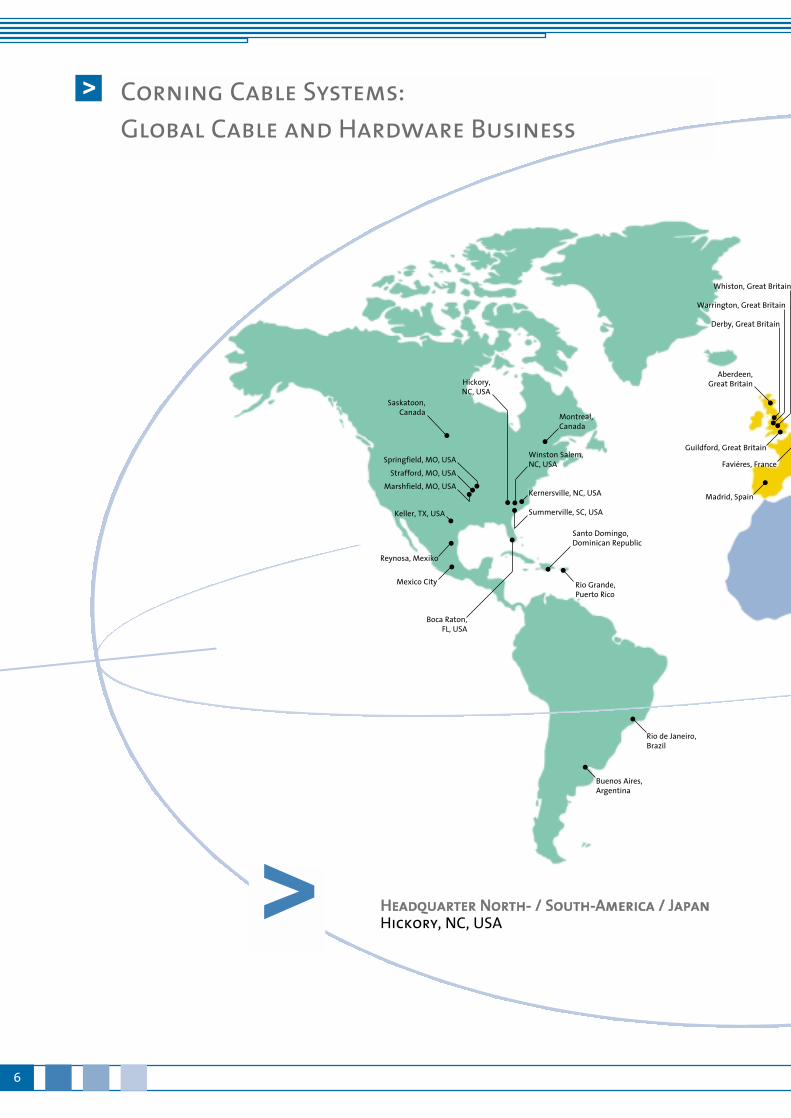
Corning Cable Systems is committed to providing superior product quality and customer support services. Our global presence is your gain.
Because, wherever you are, Corning is close at hand.
Our quality and environmental management systems are certified of course to DIN EN ISO 9001 and ISO 14001.
6
Corning Cable Systems:Global Cable and Hardware Business
Depending on the requirements, we specify either standard single-mode fibers (SSMF) conforming to ITU-T G.652 or non-zero dispersion-shifted fibers (NZ-DSF) confirming to ITU-T G.655.
SMF-28™ FiberProven Performance, Worldwide
The Standard for Performance
Corning® SMF-28™ single-mode fiber has set the standard forvalue and performance in optical networks worldwide. Triedand tested around the globe, it is widely deployed in telephony,cable television, and utility networks for the transmission of voice, data, and video services.
Corning believes that SMF-28 fiber provides the best overallpackage of optical, mechanical, and geometrical performanceavailable today. Taking advantage of today’s high capacity,low-cost transmission components developed for the 1310nm window, SMF-28 fiber features low dispersion and is optimized for use in the 1310 nm wavelength region. SMF-28fiber also can be used effectively with TDM and WDM systems operating in the 1550 nm wavelength region.
Protection and Versatility
The mechanical and chemical properties of CPC 6 coatingoffer a high degree of protection to SMF-28 fiber. Even underextreme environmental conditions, neither the coating northe glass is adversely affected by the filling compound, wateror temperature. The dual- layer UV cured acrylic coatingensures outstanding strippability and a particularly low sensitivity to microbending. The extremely precise applicationof CPC 6 coating (245 ± 5 mm) ensures that SMF-28 fiberexhibits uniform optical characteristics during fiber coloringand fiber ribbon production processes.
Features and Benefits of SMF-28
Is the most widely deployed fiber in the world Provides versatility in 1310 nm and 1550 nm applicationsProduces exceptional product consistency and reliabilitythrough OVD manufacturing processOffers the industry’s best geometrical properties for low splice loss and high splice yields
Corning Cable Systems 11
LEAF Optical Fiber
For Multi-Window Application
LEAF (Large Effective Area Fiber) fiber represents the latestgeneration of non-zero dispersion-shifted (NZ-DSF) opticalfiber, outperforming conventional NZ-DSF designs. Its lowdispersion in the 1530 – 1565 nm range makes this optical fiberideal for transmission in high bit-rate WDM applications overlong distances requiring only a minimal amount of externaldispersion compensation.
The Large Effective Area Advantage
LEAF fiber’s large effective area design reduces the lightintensity which leads to non-linear distortion of signals inWDM transmission. These non-linear effects include four wavemixing, self phase modulation and cross phase modulation.LEAF fibre combines low attenuation and low dispersion withan effective area typically 32% larger than conventional non-zero dispersion-shifted fiber. This allows more power to bepumped into networks and greater distances to be spannedbetween regeneration sites.
Reduce Network Costs
In addition to outstanding performance, LEAF fiber also canprovide cost savings over the lifetime of a network. Systemsusing LEAF fiber require fewer amplifiers and compensatorsthan systems upgraded using standard single-mode fiber.System upgrades can be accomplished efficiently by addingwavelength channels as the data handling capacity of thesystem increases.
Quality – Proven Millions of Times
LEAF fiber is manufactured using the OVD process, responsi-ble for greater volumes of fibre production than any otherprocess.Because LEAF fiber is specified beyond the requirements ofinternational standards, better splicing is possible with lowersplice loss and higher splice yields. The CPC 6 coating providesexcellent protection against extreme environmental conditions.
The Next Generation
LEAF fiber can also be used in the 1565 – 1625 nm range (L-Band), which will become ever more important in the future.In both C-Band (1530 – 1565 nm) and L-Band operation, LEAFfiber demonstrates superior transmission performance overconventional NZ-DS fibres through its ability to suppressnon-linear distortions.
12
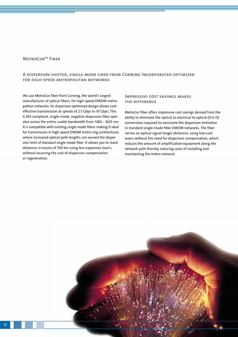
We use MetroCor fiber from Corning, the world’s largestmanufacturer of optical fibers, for high-speed DWDM metro-politan networks. Its dispersion-optimized design allows cost-effective transmission at speeds of 2.5 Gbps to 10 Gbps. ThisG.655 compliant, single-mode, negative dispersion fiber oper-ates across the entire usable bandwidth from 1280 – 1625 nm.It is compatible with existing single-mode fibers making it idealfor transmission in high-speed DWDM metro ring architectureswhere increased optical path lengths can exceed the disper-sion limit of standard single-mode fiber. It allows you to reachdistances in excess of 350 km using less expensive lasers,without incurring the cost of dispersion compensation or regeneration.
Impressive cost savings makes the difference
MetroCor fiber offers impressive cost savings derived from theability to eliminate the optical to electrical to optical (O-E-O)conversions required to overcome the dispersion limitation in standard single-mode fiber DWDM networks. The fibercarries an optical signal longer distances, using low-costlasers without the need for dispersion compensation, whichreduces the amount of amplification equipment along thenetwork path thereby reducing costs of installing and maintaining the metro network.
MetroCor™ Fiber
A dispersion shifted, single-mode fiber from Corning Incorporated optimized for high-speed metropolitan networks
Corning Cable Systems 13
Fiber Optic Duct and Buried Cables
CORNING CABLE SYSTEMS
14
Fiber optic duct and buried cables: security with FiberWay
>
Fiber Optic D
uctand Buried Cables
A break in a fiber optic cable network can result in substantialcosts for the operator. To avoid this, cables must meet highmechanical requirements and be resistant to environmentalfactors such as extreme temperatures. For this reason, ourFiberWay duct and buried fiber optic cables are designed tobe especially robust. When the appropriate cable is selectedand it is installed correctly, the cable will retain its optimalcharacteristics even when pulled into ducts or buried directly.
Fiber identification: UV coloring
All the optical fibers are colored with UV-cured acrylate color.This is a state of art coloring that guarantees a uniformlysmooth surface. For identification of fibers in one tube a scheme of twelve colors is used:
1: blue 4: brown 7: red 10: violet2: orange 5: gray 8: black 11: pink3: green 6: white 9: yellow 12: turquoise
If there are more than 12 fibers in a tube, we use a fiber bundle technique, in which 12 fibers are held together with a colored binding yarn.
We can also offer cables with fiber ribbons. A special coatingis used to combine up to 24 fibers to form a fiber ribbon.
Tube identification:
The standard system for tube identification in stranded loosetube cables is the “pilot-directional” one. The pilot tube isred, the directional one green and all other tubes are naturalcolored. Other tube identification systems according to prevailing national standards may be obtained on request.
Fibe
r O
ptic
Duc
tan
d Bu
ried
Cab
les
Corning Cable Systems 15
Cable design:meeting every requirement
We distinguish three basic design types:
Stranded tube cables: cables with stranded loose buffertubes around a central metallic or non-metallic (dielectric)strength memberCentral tube cables: cables with a central loose buffer tubeand strength elements partly embedded into the sheath Slotted core cables: cables which have a central memberwith longitudinal slots within which the fibers are positioned
In each case, the optical fibers which lie in the loose tubes orslots, are not under any tension.
High degree of water protection
Should water penetrate through a damaged point in the sheath,special fillings prevent the water from migrating along thecable. This is achieved by the use of a gel-type filling compound,or alternatively by a dry swellable element. The advantage of this so-called “dry” cable is its greater ease of installation.For additional protection against moisture, we can offercables with a laminated aluminum sheath.
Outer protection
Here we use an outer jacket of polyethylene (PE) which isresistant to stress cracking and UV radiation. Where thereare special requirements in buildings, with respect to flameretardants and halogens, we use our specially-developedFRNC (Flame Retardant, Non-Corrosive) material.
Non-metallic: the advantage
Our non-metallic (dielectric) cables offer you the followingadvantages:
No problems with grounding or potential equalizationNo lightning protection measures are requiredBuildings can be electrically isolated
Fiber Optic D
uctand Buried Cables
16
Rodent protection: resistance to damage
Damage due to rodents can be a problem mainly with directburied cables, but also when they are laid in shafts and ductsystems. Protection against rodent damage can be offered in the form of either non-metallic armoring and protectivejackets or metallic armoring. Non-metallic protection has theadvantages of a dielectric cable as described above.
Non-metallic armoring includes laminated glass-fiber yarns,which serve also as strength elements. With these, the cableremains flexible, and its diameter increases insignificantlycompared to an unarmored cable.
Greater non-metallic protection is offered by a jacket ofpolyamide, the hardest plastic used for sheathing cables.However, it makes the cable slightly larger and less flexiblethan when glass-fiber yarns are used for the armoring.
Metallic armoring is considered the most effective protectionagainst rodent damage.
Metallic armoring: optimal security for every purpose
Where high mechanical loads are involved, as is the case in direct buried installations, an additional metallic armoringis recommended. For our standard products we offer corrugatedsteel tape under the outer jacket. A special coating is used tobond the outer jacket to the steel tape. Where the mechanicalloads are exceptionally high, a further inner jacket can beinserted underneath the steel tape.
Fibe
r O
ptic
Duc
tan
d Bu
ried
Cab
les
Corning Cable Systems 17
Special print on request.
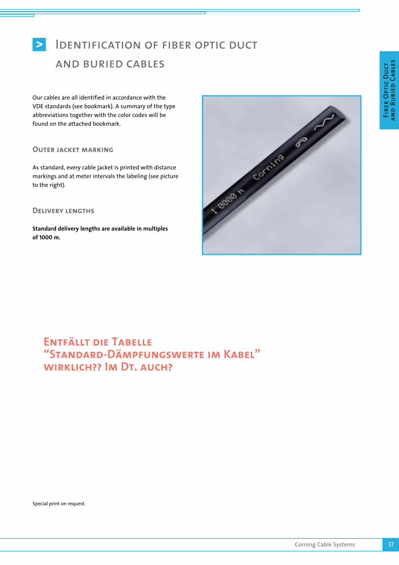
Our cables are all identified in accordance with the VDE standards (see bookmark). A summary of the typeabbreviations together with the color codes will befound on the attached bookmark.
Outer jacket marking
As standard, every cable jacket is printed with distancemarkings and at meter intervals the labeling (see pictureto the right).
Delivery lengths
Standard delivery lengths are available in multiples of 1000 m.
Identification of fiber optic duct and buried cables
>
Entfällt die Tabelle “Standard-Dämpfungswerte im Kabel” wirklich?? Im Dt. auch?
18
FiberWay: two product families
>
Fiber Optic D
uctand Buried Cables
Fiber optic cables need to exhibit a wide range of characteris-tics. Apart from the general design features already described,they must also exhibit suitable values for tensile strength,temperature cycling and bending characteristics, together withimpact and crush resistance, appropriate for the applicationand environmental conditions. Our FiberWay standard product families cover the entire range of applications in alogical way.
Stranded and central loose tube designs:
For all standard applications of cable laying with a tensileload up to 2700 N and environments with a temperaturerange from –30ºC to +70ºC. Cable design with loose fibers in stranded or central tubes.Variations: non-metallic, moisture barrier, non-metallicrodent protection, metallic armoring with or withoutinner jacket Further details see page 20.
Ribbon designs:
For all standard applications of cable laying with a tensileload up to 2700 N and environments with a temperaturerange from –30ºC to +70ºC. Cable design with fiber ribbons in stranded tubes, central tubes or slotted cores.Variations: non-metallic, metallic armoring with or without inner jacketFurther details see page 40.
We can do it>
Corning Cable Systems 19
Although our FiberWay product families are designed for awide range of applications, sometimes there is a need to findsolutions for special applications. In doing so, we can call onthe appropriate expertise.
Furthermore our sophisticated manufacturing technologyand tailor-made machines enable us to meet your particularspecifications.
In the context of specific projects, we have implemented cableswith particularly demanding requirements in relation to tensile strength of 25000 N and more, as well as for extremeclimatic conditions with a temperature range of –60ºC to+70ºC.
Our designers can also cater for special values for crush andimpact resistance or bending characteristics.
Stranded tube designdielectric central strength member(GRP), dry coredielectric central strength member(GRP), filling compoundmetallic central strength member(steel wire), filling compoundCentral tube design
A-DQ(ZN)(SR)2Y
A-DF(ZN)(SR)2Y
A-DSF(SR)2Y
A-D(ZM)(SR)2Y
31
32
33
36
A-DQ(ZN)2Y(SR)2Y
A-DF(ZN)2Y(SR)2Y
A-DSF2Y(SR)2Y
37
38
39
These designs provide a universal family of stranded tube cablesup to 432 fibers and central tube cables up to 96 fibers. Witha tensile strength of 2700 N, these are suitable for all methodsof cable laying. Their temperature range of –30ºC to +70ºCalso covers climatic conditions throughout the world.The cables are tested in accordance with IEC 60793-1, 60794-1-2.
Summary of the selection criteria for stranded and centralloose tube design cables
Fiber optic buried cable
A-DQ(ZN)2Y4Y
A-DF(ZN)2Y4Y A-DQ(BN)2Y
A-DQ(BN)H
A-DQ(ZN)2Y
A-DF(ZN)2Y
A-DSF2Y
AD-Q(ZN)H
A-D(ZM)2Y
21
22
23
34
24
25
26
27
28
2930
35
A-DQ(ZN)(L)2Y
A-DF(ZN)(L)2Y
A-DSF(L)2Y
Stranded tube designdielectric central strength member(GRP), dry coredielectric central strength member(GRP), filling compoundmetallic central strength member(steel wire), filling compound
Central tube design
Duct cable page Duct cable with page Duct cable with pagemoisture barrier dielectric rodent
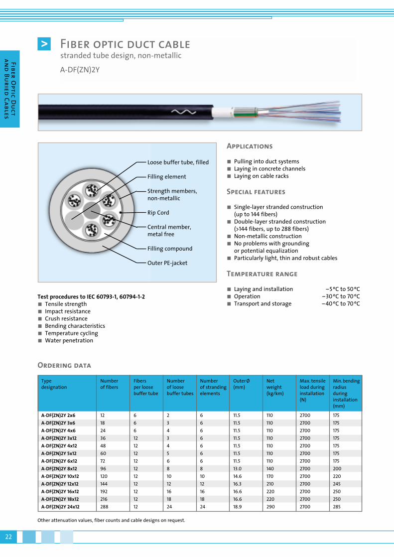
Pulling into duct systemsLaying in concrete channelsLaying on cable racks
Special features
Single-layer stranded construction (up to 144 fibers)Double-layer stranded construction (>144 fibers, up to 288 fibers)Non-metallic constructionNo problems with grounding or potential equalizationDry core constructionParticularly light, thin and robust cables
Temperature range
Laying and installation –5ºC to 50ºCOperation –30ºC to 70ºCTransport and storage –40ºC to 70ºC
Other attenuation values, fiber counts and cable designs on request.
Ordering data
Type Number Fibers Number Number OuterØ Net Max. tensile Min. bendingdesignation of fibers per loose of loose of stranding (mm) weight load during radius
buffer tube buffer tubes elements (kg/km) installation during(N) installation
Pulling into duct systemsLaying in concrete channelsLaying on cable racks
Special features
Single-layer stranded construction (up to 144 fibers)Double-layer stranded construction (>144 fibers, up to 288 fibers)Non-metallic constructionNo problems with grounding or potential equalizationParticularly light, thin and robust cables
Temperature range
Laying and installation –5ºC to 50ºCOperation –30ºC to 70ºCTransport and storage –40ºC to 70ºC
Other attenuation values, fiber counts and cable designs on request.
Ordering data
Type Number Fibers Number Number OuterØ Net Max. tensile Min. bendingdesignation of fibers per loose of loose of stranding (mm) weight load during radius
buffer tube buffer tubes elements (kg/km) installation during(N) installation
Test procedures to IEC 60793-1, 60794-1-2Tensile strengthImpact resistanceCrush resistanceBending characteristicsTemperature cyclingWater penetration
Loose buffer tube, filled
Filling element
Strength members,non-metallic
Rip Cord
Central member, metal free
Filling compound
Outer PE-jacket
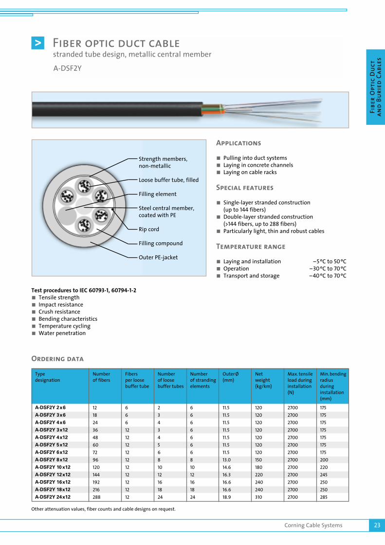
Fiber optic duct cablestranded tube design, metallic central member
A-DSF2Y
>
Corning Cable Systems 23
Fibe
r O
ptic
Duc
tan
d Bu
ried
Cab
les
Applications
Pulling into duct systemsLaying in concrete channelsLaying on cable racks
Special features
Single-layer stranded construction (up to 144 fibers)Double-layer stranded construction (>144 fibers, up to 288 fibers)Particularly light, thin and robust cables
Temperature range
Laying and installation –5ºC to 50ºCOperation –30ºC to 70ºCTransport and storage –40ºC to 70ºC
Other attenuation values, fiber counts and cable designs on request.
Ordering data
Type Number Fibers Number Number OuterØ Net Max. tensile Min. bendingdesignation of fibers per loose of loose of stranding (mm) weight load during radius
buffer tube buffer tubes elements (kg/km) installation during(N) installation
Test procedures to IEC 60793-1, 60794-1-2Tensile strengthImpact resistanceCrush resistanceBending characteristicsTemperature cyclingWater penetration
Strength members, non-metallic
Loose buffer tube, filled
Filling element
Steel central member,coated with PE
Rip cord
Filling compound
Outer PE-jacket
24
Fiber optic duct cablecentral tube design
A-D(ZM)2Y
>
Applications
Pulling into duct systemsLaying in concrete channelsLaying on cable racks
Special features
Central tube constructionParticularly light, thin and robust cables
Temperature range
Laying and installation –5ºC to 50ºCOperation –30ºC to 70ºCTransport and storage –40ºC to 70ºC
Other attenuation values, fiber counts and cable designs on request.
Ordering data
Type Number Fibers Number Number OuterØ Net Max. tensile Min. bendingdesignation of fibers per loose of loose of stranding (mm) weight load during radius
buffer tube buffer tubes elements (kg/km) installation during(N) installation
(mm)
A-D(ZM)2Y 1x8
A-D(ZM)2Y 1x10
A-D(ZM)2Y 1x12
A-D(ZM)2Y 1x16
A-D(ZM)2Y 1x20
A-D(ZM)2Y 1x24
A-D(ZM)2Y 1x36
A-D(ZM)2Y 1x48
A-D(ZM)2Y 1x96
81012162024364896
8101281012121212
111222348
4.24.24.24.24.24.2668
10.210.210.210.210.210.212.012.014.0
104104104104104104135135174
270027002700270027002700270027002700
180180180180180180215215270
Test procedures to IEC 60793-1 and 60794-1-2Tensile strengthImpact resistanceCrush resistanceBending characteristicsTemperature cyclingWater penetration
Pulling into duct systemsLaying in concrete channelsLaying on cable racks
Special features
Single-layer stranded construction (up to 144 fibers)Double-layer stranded construction (>144 fibers, up to 288 fibers)Laminated aluminum tape as additional moisture barrierDry core constructionLight, thin and robust cables
Temperature range
Laying and installation –5ºC to 50ºCOperation –30ºC to 70ºCTransport and storage –40ºC to 70ºC
Other attenuation values, fiber counts and cable designs on request.
Ordering data
Type Number Fibers Number Number OuterØ Net Max. tensile Min. bendingdesignation of fibers per loose of loose of stranding (mm) weight load during radius
buffer tube buffer tubes elements (kg/km) installation during(N) installation
Pulling into duct systemsLaying in concrete channelsLaying on cable racks
Special features
Single-layer stranded construction (up to 144 fibers)Double-layer stranded construction (>144 fibers, up to 288 fibers)Laminated aluminum tape as additional moisture barrierLight, thin and robust cables
Temperature range
Laying and installation –5ºC to 50ºCOperation –30ºC to 70ºCTransport and storage –40ºC to 70ºC
Other attenuation values, fiber counts and cable designs on request.
Ordering data
Type Number Fibers Number Number OuterØ Net Max. tensile Min. bendingdesignation of fibers per loose of loose of stranding (mm) weight load during radius
buffer tube buffer tubes elements (kg/km) installation during(N) installation
Pulling into duct systemsLaying in concrete channelsLaying on cable racksIn areas with rodentsDirect buried in sand beds
Special features
Single-layer stranded construction (up to 144 fibers)Double-layer stranded construction (>144 fibers, up to 288 fibers)Non-metallic constructionNo problems with grounding or potential equalizationDry core constructionRodent protection provided by Polyamide jacketOil-resistant, secure against termitesLight, thin and robust cables
Temperature range
Laying and installation –5ºC to 50ºCOperation –30ºC to 70ºCTransport and storage –40ºC to 70ºC
Test procedures to IEC 60793-1, 60794-1-2Tensile strengthImpact resistanceCrush resistanceBending characteristicsTemperature cyclingWater penetration
Other attenuation values, fiber counts and cable designs on request.
Ordering data
Type Number Fibers Number Number OuterØ Net Max. tensile Min. bendingdesignation of fibers per loose of loose of stranding (mm) weight load during radius
buffer tube buffer tubes elements (kg/km) installation during(N) installation
Pulling into duct systemsLaying in concrete channelsLaying on cable racksIn areas with rodentsDirect buried in sand beds
Special features
Single-layer stranded construction (up to 144 fibers)Double-layer stranded construction (>144 fibers, up to 288 fibers)Non-metallic constructionNo problems with grounding or potential equalizationRodent protection provided by Polyamide jacketOil-resistant, secure against termitesLight, thin and robust cables
Temperature range
Laying and installation –5ºC to 50ºCOperation –30ºC to 70ºCTransport and storage –40ºC to 70ºC
Test procedures to IEC 60793-1, 60794-1-2Tensile strengthImpact resistanceCrush resistanceBending characteristicsTemperature cyclingWater penetration
Other attenuation values, fiber counts and cable designs on request.
Ordering data
Type Number Fibers Number Number OuterØ Net Max. tensile Min. bendingdesignation of fibers per loose of loose of stranding (mm) weight load during radius
buffer tube buffer tubes elements (kg/km) installation during(N) installation
Pulling into duct systemsLaying in concrete channelsLaying on cable racksIn areas with rodentsDirect buried in sand beds
Special features
Single-layer stranded construction (up to 144 fibers)Double-layer stranded construction (>144 fibers, up to 288 fibers)Non-metallic constructionNo problems with grounding or potential equalizationDry core constructionRodent protection provided by laminated glass yarnLight, thin and robust cables
Temperature range
Laying and installation –5ºC to 50ºCOperation –30ºC to 70ºCTransport and storage –40ºC to 70ºC
Test procedures to IEC 60793-1, 60794-1-2Tensile strengthImpact resistanceCrush resistanceBending characteristicsTemperature cyclingWater penetration
Other attenuation values, fiber counts and cable designs on request.
Ordering data
Type Number Fibers Number Number OuterØ Net Max. tensile Min. bendingdesignation of fibers per loose of loose of stranding (mm) weight load during radius
buffer tube buffer tubes elements (kg/km) installation during(N) installation
Direct burialIn applications with high mechanical loadsIn areas with rodents
Special features
Single-layer stranded construction (up to 144 fibers)Double-layer stranded construction (>144 fibers, up to 288 fibers)Corrugated steel tape as protection againstrodents and mechanical damageDry core constructionThin and robust cables
Temperature range
Laying and installation –5ºC to 50ºCOperation –30ºC to 70ºCTransport and storage –40ºC to 70ºC
Other attenuation values, fiber counts and cable designs on request.
Ordering data
Type Number Fibers Number Number OuterØ Net Max. tensile Min. bendingdesignation of fibers per loose of loose of stranding (mm) weight load during radius
buffer tube buffer tubes elements (kg/km) installation during(N) installation
Direct burialIn applications with high mechanical loadsIn areas with rodents
Special features
Single-layer stranded construction (up to 144 fibers)Double-layer stranded construction (>144 fibers, up to 288 fibers)Corrugated steel tape as protection againstrodents and mechanical damageThin and robust cables
Temperature range
Laying and installation –5ºC to 50ºCOperation –30ºC to 70ºCTransport and storage –40ºC to 70ºC
Other attenuation values, fiber counts and cable designs on request.
Ordering data
Type Number Fibers Number Number OuterØ Net Max. tensile Min. bendingdesignation of fibers per loose of loose of stranding (mm) weight load during radius
buffer tube buffer tubes elements (kg/km) installation during(N) installation
Pulling into duct systemsLaying in concrete channelsLaying on cable racks
Special features
Single-layer stranded construction (up to 144 fibers)Double-layer stranded construction (>144 fibers, up to 288 fibers)Non-metallic constructionNo problems with grounding or potential equalizationDry core constructionParticularly light, thin and robust cables
Temperature range
Laying and installation –5ºC to 50ºCOperation –30ºC to 70ºCTransport and storage –40ºC to 70ºC
Other attenuation values, fiber counts and cable designs on request.
Ordering data
Type Number Fibers Number Number OuterØ Net Max. tensile Min. bendingdesignation of fibers per loose of loose of stranding (mm) weight load during radius
buffer tube buffer tubes elements (kg/km) installation during(N) installation
Pulling into duct systemsLaying in concrete channelsLaying on cable racksIn areas with rodentsDirect buried in sand beds
Special features
Single-layer stranded construction (up to 144 fibers)Double-layer stranded construction (>144 fibers, up to 288 fibers)Non-metallic constructionNo problems with grounding or potential equalizationDry core constructionRodent protection provided by laminated glass yarnLight, thin and robust cables
Temperature range
Laying and installation –5ºC to 50ºCOperation –30ºC to 70ºCTransport and storage –40ºC to 70ºC
Test procedures to IEC 60793-1, 60794-1-2Tensile strengthImpact resistanceCrush resistanceBending characteristicsTemperature cyclingWater penetration
Other attenuation values, fiber counts and cable designs on request.
Ordering data
Type Number Fibers Number Number OuterØ Net Max. tensile Min. bendingdesignation of fibers per loose of loose of stranding (mm) weight load during radius
buffer tube buffer tubes elements (kg/km) installation during(N) installation
Direct burialIn applications with high mechanical loadsIn areas with rodents
Special features
Central tube constructionCorrugated steel tape as protection againstrodents and mechanical damageThin and robust cables
Temperature range
Laying and installation –5ºC to 50ºCOperation –30ºC to 70ºCTransport and storage –40ºC to 70ºC
Ordering data
Type Number Fibers Number Central OuterØ Net Max. tensile Min. bendingdesignation of fibers per fiber of fiber buffer tube (mm) weight load during radius
Other attenuation values, fiber counts and cable designs on request.
Test procedures to IEC 60793-1 and 60794-1-2Tensile strengthImpact resistanceCrush resistanceBending characteristicsTemperature cyclingWater penetration
Other attenuation values, fiber counts and cable designs on request.
Ordering data
Type Number Fibers Number Number OuterØ Net Max. tensile Min. bendingdesignation of fibers per loose of loose of stranding (mm) weight load during radius
buffer tube buffer tubes elements (kg/km) installation during(N) installation
Direct burialWhere there are particularly high mechanicalloadsIn areas with rodents
Special features
Single-layer stranded construction (up to 144 fibers)Double-layer stranded construction (>144 fibers, up to 288 fibers)Corrugated steel tape as protection againstrodents and mechanical damageDry core constructionParticularly robust cables
Temperature range
Laying and installation –5ºC to 50ºCOperation –30ºC to 70ºCTransport and storage –40ºC to 70ºC
Test procedures to IEC 60793-1, 60794-1-2Tensile strengthImpact resistanceCrush resistanceBending characteristicsTemperature cyclingWater penetration
Direct burialWhere there are particularly high mechanicalloadsIn areas with rodents
Special features
Single-layer stranded construction (up to 144 fibers)Double-layer stranded construction (>144 fibers, up to 288 fibers)Corrugated steel tape as protection againstrodents and mechanical damageParticularly robust cables
Temperature range
Laying and installation –5ºC to 50ºCOperation –30ºC to 70ºCTransport and storage –40ºC to 70ºC
Other attenuation values, fiber counts and cable designs on request.
Ordering data
Type Number Fibers Number Number OuterØ Net Max. tensile Min. bendingdesignation of fibers per loose of loose of stranding (mm) weight load during radius
buffer tube buffer tubes elements (kg/km) installation during(N) installation
Direct burialWhere there are particularly high mechanicalloadsIn areas with rodents
Special features
Single-layer stranded construction (up to 144 fibers)Double-layer stranded construction (>144 fibers, up to 288 fibers)Corrugated steel tape as protection againstrodents and mechanical damageParticularly robust cables
Temperature range
Laying and installation –5ºC to 50ºCOperation –30ºC to 70ºCTransport and storage –40ºC to 70ºC
Test procedures to IEC 60793-1, 60794-1-2Tensile strengthImpact resistanceCrush resistanceBending characteristicsTemperature cyclingWater penetration
Strength members, non-metallic
Loose buffer tube, filled
Filling element
Steel central member,coated with PE (over 6x12)
Filling compound
Corrugated steel tape
3 rip cords
Inner PE-jacket
Outer PE-jacket
Other attenuation values, fiber counts and cable designs on request.
Ordering data
Type Number Fibers Number Number OuterØ Net Max. tensile Min. bendingdesignation of fibers per loose of loose of stranding (mm) weight load during radius
buffer tube buffer tubes elements (kg/km) installation during(N) installation
The FiberWay Ribbon Cable family includes cable designswith fiber ribbons in stranded loose tubes up to 864 fibers, in central tube cables up to 432 fibers and slotted core cablesup to 1000 fibers. With a tensile strength of 2700 N, these aresuitable for all methods of cable laying. Their temperaturerange of –30ºC to +70ºC also covers almost all climatic conditions throughout the world.Our fiber ribbons are very easy to split up into individual fibers(peelable), too, so that there is no problem in connecting tointerfaces of existing networks which have individual fibers.It is possible to splice up to twelve fibers simultaneously,reducing the time necessary for splicing.
The fiber ribbons are distinguishable from each other by acount number printed on them.The cables are tested in accordance with IEC 60793-1 and60794-1-2.
Summary of the selection criteria for FiberWay Ribbon designs cables
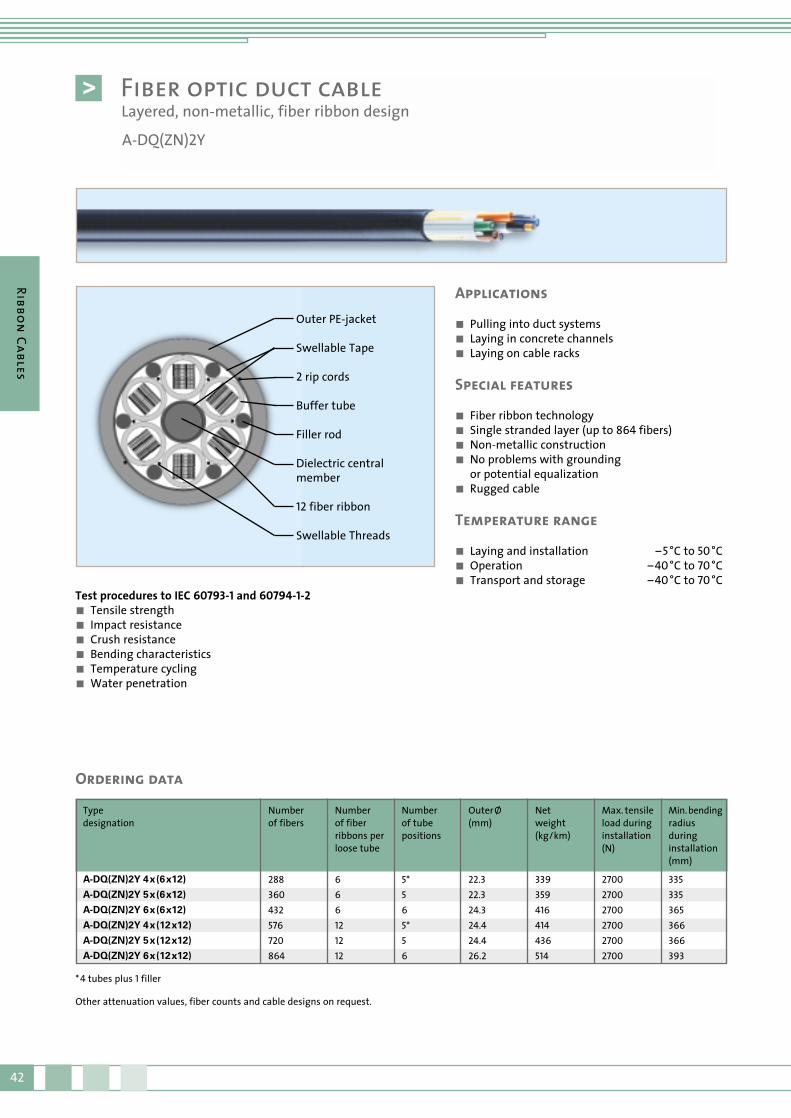
Pulling into duct systemsLaying in concrete channelsLaying on cable racks
Special features
Fiber ribbon technologySingle stranded layer (up to 864 fibers)Non-metallic constructionNo problems with grounding or potential equalizationRugged cable
Temperature range
Laying and installation –5°C to 50°COperation –40°C to 70°CTransport and storage –40°C to 70°C
*4 tubes plus 1 filler
Other attenuation values, fiber counts and cable designs on request.
Ordering data
Type Number Number Number OuterØ Net Max. tensile Min. bendingdesignation of fibers of fiber of tube (mm) weight load during radius
ribbons per positions (kg/km) installation during loose tube (N) installation
(mm)
A-DQ(ZN)2Y 4x(6x12)
A-DQ(ZN)2Y 5x(6x12)
A-DQ(ZN)2Y 6x(6x12)
A-DQ(ZN)2Y 4x(12x12)
A-DQ(ZN)2Y 5x(12x12)
A-DQ(ZN)2Y 6x(12x12)
288360432576720864
666121212
5*565*56
22.322.324.324.424.426.2
339359416414436514
270027002700270027002700
335335365366366393
Test procedures to IEC 60793-1 and 60794-1-2Tensile strengthImpact resistanceCrush resistanceBending characteristicsTemperature cyclingWater penetration
Pulling into duct systemsLaying in concrete channelsLaying on cable racks
Special features
Fiber ribbon technologyCentral tube constructionNon-metallic constructionNo problems with grounding or potential equalizationLight, thin and robust cables
Temperature range
Laying and installation –5ºC to 50ºCOperation –30ºC to 70ºCTransport and storage –40ºC to 70ºC
Ordering data
Type Number Fibers Number Central OuterØ Net Max. tensile Min. bendingdesignation of fibers per fiber of fiber buffer (mm) weight load during radius
ribbon ribbons tubeØ (kg/km) installation during (mm) (N) installation
(mm)
A-D(ZN)(2ZN)2Y 1x12
A-D(ZN)(2ZN)2Y 2x12
A-D(ZN)(2ZN)2Y 4x12
A-D(ZN)(2ZN)2Y 5x12
A-D(ZN)(2ZN)2Y 6x12
A-D(ZN)(2ZN)2Y 8x12
A-D(ZN)(2ZN)2Y 10x12
A-D(ZN)(2ZN)2Y 12x12
A-D(ZN)(2ZN)2Y 16x12
A-D(ZN)(2ZN)2Y 18x12
122448607296120144192216
12121212121212121212
44456810121618
8.08.08.08.08.08.010.510.510.510.5
13.913.9 13.9 13.9 13.913.915.8 15.8 15.8 15.8
164164164164164164210210210210
2700270027002700270027002700270027002700
210210210210210210237237237237
Other attenuation values, fiber counts and cable designs on request.
Test procedures to IEC 60793-1 and 60794-1-2Tensile strengthImpact resistanceCrush resistanceBending characteristicsTemperature cyclingWater penetration
Other attenuation values, fiber counts and cable designs on request.
Ordering data
Type Number Fibers Number Central OuterØ Net Max. tensile Min. bendingdesignation of fibers per fiber of fiber buffer (mm) weight load during radius
ribbon ribbons tubeØ (kg/km) installation during (mm) (N) installation
(mm)
A-D(ZN)(2ZN)2Y 1x12
A-D(ZN)(2ZN)2Y 2x12
A-D(ZN)(2ZN)2Y 4x12
A-D(ZN)(2ZN)2Y 5x12
A-D(ZN)(2ZN)2Y 6x12
A-D(ZN)(2ZN)2Y 8x12
A-D(ZN)(2ZN)2Y 10x12
A-D(ZN)(2ZN)2Y 12x12
A-D(ZN)(2ZN)2Y 16x12
A-D(ZN)(2ZN)2Y 18x12
122448607296120144192216
12121212121212121212
44456810121618
8.08.08.08.08.08.010.510.510.510.5
15.515.515.515.515.515.517.817.817.817.8
234234234234234234293293293293
2700270027002700270027002700270027002700
233233233233233233267267267267
Applications
Direct burialIn applications with high mechanical loadsIn areas with rodents
Special features
Fiber ribbon technologyCentral tube constructionCorrugated steel tape as protection againstrodents and mechanical damageThin and robust cables
Temperature range
Laying and installation –5ºC to 50ºCOperation –30ºC to 70ºCTransport and storage –40ºC to 70ºC
Test procedures to IEC 60793-1 and 60794-1-2Tensile strengthImpact resistanceCrush resistanceBending characteristicsTemperature cyclingWater penetration
Pulling into duct systemsLaying in concrete channelsLaying on cable racks
Special features
Fiber ribbon technologyCentral tube constructionNon-metallic constructionNo problems with grounding or potential equalizationLight, thin and robust cables
Temperature range
Laying and installation –5ºC to 50ºCOperation –40ºC to 70ºCTransport and storage –40ºC to 70ºC
Ordering data
Type Number Fibers Number Central OuterØ Net Max. tensile Min. bendingdesignation of fibers per fiber of fiber buffer (mm) weight load during radius
ribbon ribbons tubeØ (kg/km) installation during (mm) (N) installation
(mm)
A-D(ZN)(2ZN)2Y 10x24
A-D(ZN)(2ZN)2Y 12x24
A-D(ZN)(2ZN)2Y 18x24
A-D(ZN)(2ZN)2Y
A-D(ZN)(2ZN)2Y
240288432576720
24242424/3624/36
101218
14.214.214.217.917.9
20.120.120.124.024.0
322322322453453
27002700270027002700
302302302360360
Other attenuation values, fiber counts and cable designs on request.
Test procedures to IEC 60793-1 and 60794-1-2Tensile strengthImpact resistanceCrush resistanceBending characteristicsTemperature cyclingWater penetration
Pulling into duct systemsLaying in concrete channelsLaying on cable racks
Special features
Fiber ribbon technologyCentral tube constructionNon-metallic constructionNo problems with grounding or potential equalizationLight, thin and robust cables
Temperature range
Laying and installation –5ºC to 50ºCOperation –40ºC to 70ºCTransport and storage –40ºC to 70ºC
Other attenuation values, fiber counts and cable designs on request.
Ordering data
Type Number Fibers Number Central OuterØ Net Max. tensile Min. bendingdesignation of fibers per fiber of fiber buffer (mm) weight load during radius
ribbon ribbons tubeØ (kg/km) installation during (mm) (N) installation
(mm)
A-D(ZM)(SR)2Y 10x24
A-D(ZM)(SR)2Y 12x24
A-D(ZM)(SR)2Y 18x24
240288432
242424
101218
14.214.214.2
21.321.321.3
442442442
270027002700
319319319
Test procedures to IEC 60793-1 and 60794-1-2Tensile strengthImpact resistanceCrush resistanceBending characteristicsTemperature cyclingWater penetration
Outer PE-jacket
Corrugated steel tapearmor
Water-swellable tape
Steel strength members
Rip cords
Buffer tube
Fiber ribbons
Filling compound
48
FutureLinkFiber optic Multi-Purpose and Campus Cables
CORNING CABLE SYSTEMS
>
Corning Cable Systems 49
Fiber
Opt
ic M
ulti
Purp
ose
and
Cam
pus C
able
s
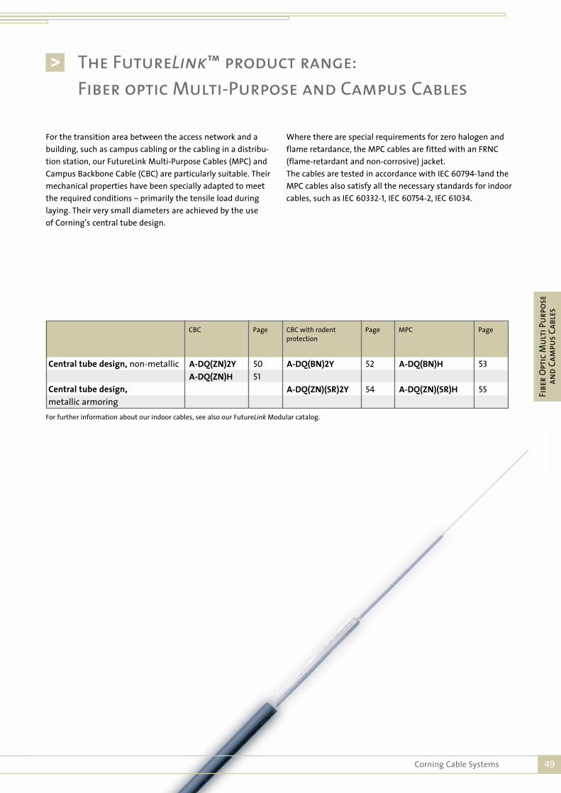
The FutureLink™ product range:Fiber optic Multi-Purpose and Campus Cables
For further information about our indoor cables, see also our FutureLink Modular catalog.
A-DQ(BN)H
A-DQ(ZN)(SR)H
A-DQ(ZN)2YA-DQ(ZN)H
5051
52
54
53
55
A-DQ(BN)2Y
A-DQ(ZN)(SR)2Y
Central tube design, non-metallic
Central tube design, metallic armoring
CBC Page CBC with rodent Page MPC Pageprotection
For the transition area between the access network and abuilding, such as campus cabling or the cabling in a distribu-tion station, our FutureLink Multi-Purpose Cables (MPC) andCampus Backbone Cable (CBC) are particularly suitable. Theirmechanical properties have been specially adapted to meetthe required conditions – primarily the tensile load duringlaying. Their very small diameters are achieved by the use of Corning’s central tube design.
Where there are special requirements for zero halogen andflame retardance, the MPC cables are fitted with an FRNC(flame-retardant and non-corrosive) jacket.The cables are tested in accordance with IEC 60794-1and theMPC cables also satisfy all the necessary standards for indoorcables, such as IEC 60332-1, IEC 60754-2, IEC 61034.
50
Campus Backbone Cablenon-metallic
A-DQ(ZN)2Y
>
Fiber Optic Multi Purpose
and Campus Cables
Applications
Use within and between buildingsPulling into duct systemsLaying in concrete channelsLaying on cable racks
Special features
Central tube constructionNon-metallic and dry constructionNo problems with grounding or potential equalizationEspecially light, thin and robust cables
Temperature range
Laying and installation –5ºC to 50ºCOperation –20ºC to 60ºCTransport and storage –25ºC to 70ºC
Other attenuation values, fiber counts and cable designs on request.
Ordering data
Type Number Fibers Number Central OuterØ Net Max. tensile Min. bendingdesignation of fibers per fiber of fiber buffer (mm) weight load during radius
bundle bundles tubeØ (kg/km) installation during (mm) (N) installation
(mm)
A-DQ(ZN)2Y 1x2
A-DQ(ZN)2Y 1x4
A-DQ(ZN)2Y 1x6
A-DQ(ZN)2Y 1x8
A-DQ(ZN)2Y 1x12
A-DQ(ZN)2Y 1x16
A-DQ(ZN)2Y 1x24
2468121624
246812812
1111122
3.53.53.53.53.566
6.56.56.56.56.58.68.6
33333333336060
1500150015001500150015001500
140140140140140220220
Test procedures to IEC 60793-1, 60794-1-2Tensile strengthImpact resistanceCrush resistanceBending characteristicsTemperature cyclingWater penetration
Use within and between buildings, along gradients or horizontallyPulling into duct systemsLaying in concrete channelsLaying on cable racks
Special features
Central tube constructionNon-metallic and dry constructionNo problems with grounding or potential equalizationHalogen-free, flame-retardant, non-corrosive and low-smokeEspecially light, thin and robust cables
Temperature range
Laying and installation –5ºC to 50ºCOperation –20ºC to 60ºCTransport and storage –25ºC to 70ºC
Other attenuation values, fiber counts and cable designs on request.
Ordering data
Type Number Fibers Number Central OuterØ Net Max. tensile Min. bendingdesignation of fibers per fiber of fiber buffer (mm) weight load during radius
bundle bundles tubeØ (kg/km) installation during (mm) (N) installation
(mm)
A-DQ(ZN)H 1x2
A-DQ(ZN)H 1x4
A-DQ(ZN)H 1x6
A-DQ(ZN)H 1x8
A-DQ(ZN)H 1x12
A-DQ(ZN)H 1x16
A-DQ(ZN)H 1x24
2468121624
246812812
1111122
3.53.53.53.53.555
6.56.56.56.56.588
45454545456565
80080080080080011001100
140140140140140190190
Test procedures to IEC 60793-1, 60794-1-2 also satisfies all relevant standards for indoor cables:IEC 60332-1, IEC 60754-2, IEC 61034
Use within and between buildingsPulling into duct systemsLaying in concrete channelsLaying on cable racksIn areas with rodents
Special features
Central tube constructionNon-metallic and dry constructionNo problems with grounding or potential equalizationRodent protection provided by laminated glass yarnEspecially light, thin and robust cables
Temperature range
Laying and installation –5ºC to 50ºCOperation –20ºC to 60ºCTransport and storage –25ºC to 70ºC
Other attenuation values, fiber counts and cable designs on request.
Ordering data
Type Number Fibers Number Central OuterØ Net Max. tensile Min. bendingdesignation of fibers per fiber of fiber buffer (mm) weight load during radius
bundle bundles tubeØ (kg/km) installation during (mm) (N) installation
(mm)
A-DQ(BN)2Y 1x2
A-DQ(BN)2Y 1x4
A-DQ(BN)2Y 1x6
A-DQ(BN)2Y 1x8
A-DQ(BN)2Y 1x12
A-DQ(BN)2Y 1x16
A-DQ(BN)2Y 1x24
2468121624
24681282
1111122
3.53.53.53.53.555
7.57.57.57.57.59.09.0
5050 50 50 50 6565
80080080080080011001100
170170170170170190190
Test procedures to IEC 60793-1, 60794-1-2Tensile strengthImpact resistanceCrush resistanceBending characteristicsTemperature cyclingWater penetration
Use within and between buildings, along gradients or horizontallyPulling into duct systemsLaying in concrete channelsLaying on cable racksIn areas with rodents
Special features
Central tube constructionNon-metallic and dry constructionNo problems with grounding or potential equalizationHalogen-free, flame-retardant, non-corrosive and low-smokeRodent protection provided by laminated glass yarnEspecially light, thin and robust cables
Temperature range
Laying and installation –5ºC to 50ºCOperation –20ºC to 60ºCTransport and storage –25ºC to 70ºC
Central loose buffer tube,filled
Filling compound
Fibers
Glasgarnarmierung
Outer FRNC-jacket
54
>
Fiber Optic Multi Purpose
and Campus Cables
Campus Backbone Cablecorrugated steel tape
A-DQ(ZN)(SR)2Y
Applications
Use within and between buildingsPulling into duct systemsLaying in concrete channelsLaying on cable racksIn areas with rodents
Special features
Central tube constructionCorrugated steel tape as protection againstrodents and mechanical damageLight, thin and robust cables
Temperature range
Laying and installation –5ºC to 50ºCOperation –20ºC to 60ºCTransport and storage –25ºC to 70ºC
Other attenuation values, fiber counts and cable designs on request.
Ordering data
Type Number Fibers Number Central OuterØ Net Max. tensile Min. bendingdesignation of fibers per fiber of fiber buffer (mm) weight load during radius
bundle bundles tubeØ (kg/km) installation during (mm) (N) installation
(mm)
A-DQ(ZN)(SR)2Y 1x2
A-DQ(ZN)(SR)2Y 1x4
A-DQ(ZN)(SR)2Y 1x6
A-DQ(ZN)(SR)2Y 1x8
A-DQ(ZN)(SR)2Y 1x12
A-DQ(ZN)(SR)2Y 1x16
A-DQ(ZN)(SR)2Y 1x24
2468121624
246812812
1111122
3.03.03.03.03.05.05.0
7.97.97.97.97.99.79.7
70707070709595
80080080080080011001100
180180180180180220220
Test procedures to IEC 60793-1, 60794-1-2Tensile strengthImpact resistanceCrush resistanceBending characteristicsTemperature cyclingWater penetration
Use within and between buildings, along gradients or horizontallyPulling into duct systemsLaying in concrete channelsLaying on cable racksIn areas with rodents
Special features
Central tube constructionCorrugated steel tape as protection againstrodents and mechanical damageHalogen-free, flame-retardant, non-corrosive and low-smokeLight, thin and robust cables
Temperature range
Laying and installation –5ºC to 50ºCOperation –20ºC to 60ºCTransport and storage –25ºC to 70ºC
Central loose buffer tube,filled
Strength members, non-metallic
Fibers
Corrugated steel tape
Outer FRNC-jacket
56
> Notes
Corning Cable Systems 57
Additional Information
CORNING CABLE SYSTEMS
58
>
AdditionalInform
ation
Corning accessories: solutions for all fiber networks
Wherever cables have to be joined, branched, distributed or terminated, Corning Cable Systems has excellent solutionsto offer. This applies to the transmission of voice and dataover both copper and optical cable networks.
The product range extends from main distribution systems in exchanges through to closures for all types of network tothe terminal distribution box or cross-connect. This range ofproducts makes Corning Cable Systems one of the world’slargest cable system providers.
Some examples from the comprehensive product rangebeing used by traditional telecommunication companies andcarriers worldwide:
Closures for fiber optic cablesFiber splicersDistribution systems for fiber optic cablesFiber optic connectors
The full range of Corning’s products for fiber optic networksis presented in our catalog entitled “Accessories for fiberoptic networks”, order no. A45050-W3093-R7-X-7600.For further information about these product groups pleasecontact our sales representatives.
Corning Cable Systems 59
Addi
tion
alIn
form
atio
n
Training: expertise for your personnel
Total solutions are becoming ever more important for communication networks. Of particular importance in thiscontext are solutions for local networks (LANs) for use oncustomer premises, and in the carrier area (e.g. telecommuni-cation, CATV IP networks) because the future lies in the integration of speech, image and data.
At the same time, as world-spanning information infrastruc-ture grows, also the quality requirements to be met by net-worked communication solutions are growing. This demandsknowledge – knowledge that we can pass on to you.
No-one can do everything – but everything can be learned
Techniques and products are subject to constant change. This makes it essential to have staff trained to the highestlevels, who know how to utilize technical progress to youradvantage. This can only be achieved by continuous training.
Knowledge is precious – which is why we pass it on
As a leading manufacturer of communication cables and networks we are working with our customers to buildcommunication bridges for the 21st century.
We realize that the planning, installation and maintenanceof cable systems involves comprehensive knowledge – something we want to share with you as part of a genuinepartnership.
We do the training – you get the profit
Our worldwide knowledge in cable and network technologyis channeled into our Training Center. On the basis of thisknowledge, we develop diverse seminars for your staff.
Our training is aimed at all those who set up or operate carrier or customer premise cable networks.
Training>
Detaillierte Informationen zu aktuellen Kursen und Terminen erhalten Sie bei Ihrem lokalen Corning-Vertreter
und auf unserer Internet-Homepage:http://www.corning.com/cablesystems/de
By undertaking training before starting on a project you will avoid costly installation errors, and will put in place a critical prerequisite for the successful implementation of your project.
Practical orientation, not theoretical dreams
The balance is critical: theory is necessary, but practicalitydictates what must be done. From their many years of practi-cal experience, our trainers know which knowledge and skillsare required for each task, and they are in constant contactwith development, sales and projects engineering at CorningCable Systems.
Übersetzung fehlt!!
60
AdditionalInform
ation
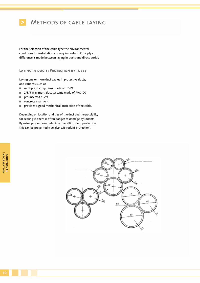
> Methods of cable laying
For the selection of the cable type the environmental conditions for installation are very important. Principly a difference is made between laying in ducts and direct burial.
Laying in ducts: Protection by tubes
Laying one or more duct cables in protective ducts, and variants such as
multiple duct systems made of HD PE2/3/5-way multi duct systems made of PVC 100pre-inserted ductsconcrete channelsprovides a good mechanical protection of the cable.
Depending on location and size of the duct and the possibilityfor sealing it, there is often danger of damage by rodents. By using proper non-metallic or metallic rodent protectionthis can be prevented (see also p.16 rodent protection).
Corning Cable Systems 61
Addi
tion
alIn
form
atio
n
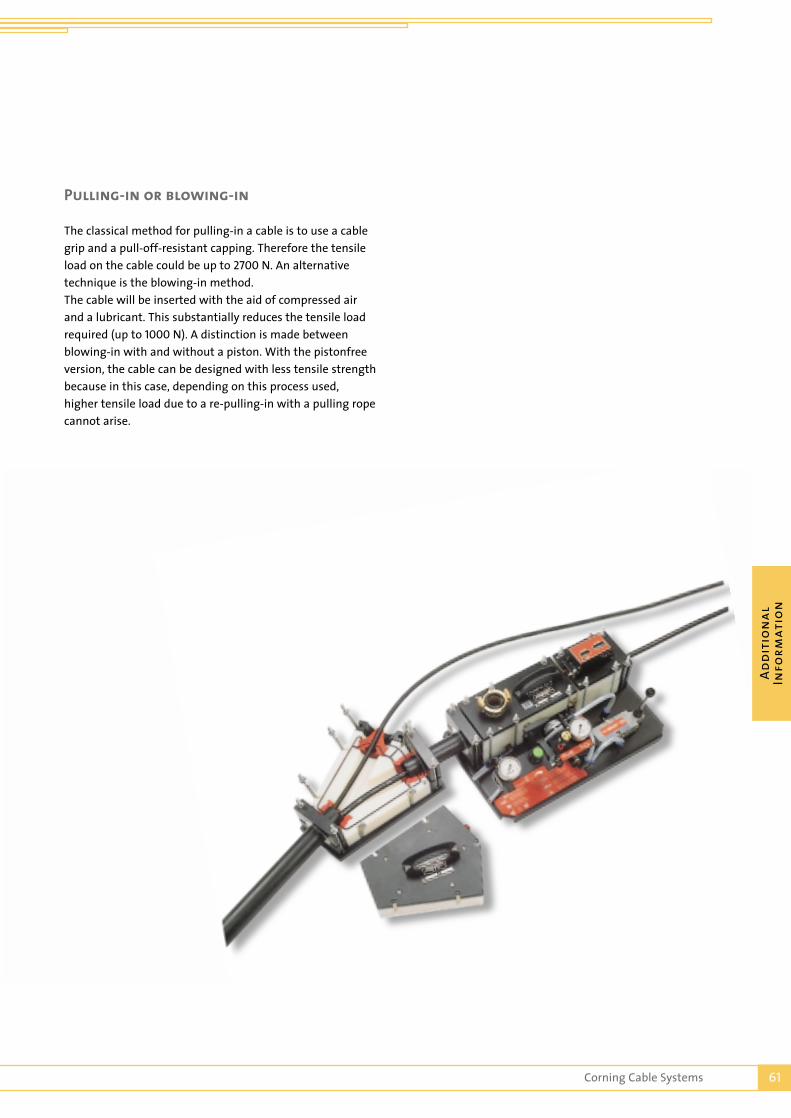
Pulling-in or blowing-in
The classical method for pulling-in a cable is to use a cablegrip and a pull-off-resistant capping. Therefore the tensileload on the cable could be up to 2700 N. An alternative technique is the blowing-in method. The cable will be inserted with the aid of compressed air and a lubricant. This substantially reduces the tensile loadrequired (up to 1000 N). A distinction is made between blowing-in with and without a piston. With the pistonfreeversion, the cable can be designed with less tensile strengthbecause in this case, depending on this process used, higher tensile load due to a re-pulling-in with a pulling ropecannot arise.
AdditionalInform
ation
62
Typical cross-section of a cable trench
Sand bed
Relay
Refill andpack down
Warning tape
Sand or stone-free soil
Fiber optic buried cable
Level trench floor
Top surface
Filler material
Direct burial:Protection by metallic armoring
In a typical cable trench the cable is laid in a sand bed.However not all ground locations will support this. Using a metallic armoring (see also p. 18 metallic armoring)will protect our buried cables against stones and other mechanical loads.
Laying-in, pulling-in or plowing-in
Laying-in means the cable is laid alongside the trench and lifted in over the edge of the trench.Pulling-in means the cable is pulled into the trenchlengthwise, over rollers.Plowing-in means using a special plow. This digs a trenchand in one operation the cable is pulled in and the trenchis refilled.
All 3 methods work with a tensile load of up to 2700 N.
>
Corning Cable Systems 63
Addi
tion
alIn
form
atio
n
Notes
AdditionalInform
ation
64
Addi
tion
alIn
form
atio
n
Corning Cable Systems 65
AdditionalInform
ation
66
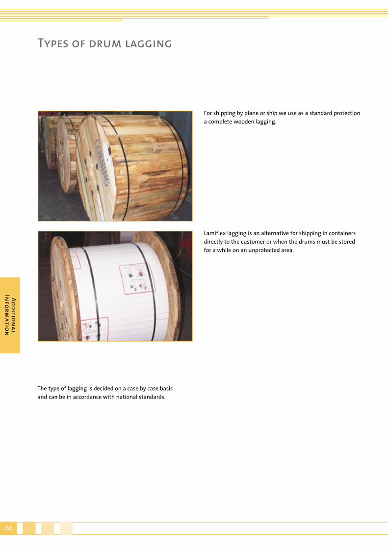
For shipping by plane or ship we use as a standard protectiona complete wooden lagging.
Lamiflex lagging is an alternative for shipping in containersdirectly to the customer or when the drums must be storedfor a while on an unprotected area.
The type of lagging is decided on a case by case basis and can be in accordance with national standards.
Types of drum lagging
Corning Cable Systems 67
Addi
tion
alIn
form
atio
n
Technical terms>
AbsorptionThe reduction in strength (loss) of radiation as it passesthrough a material (for light, part of the radiation energyis converted into heat for example)
ACRAttenuation to crosstalk ratio
ArmoringProtective element (generally made of steel tapes, wiresor belts) for cables used under special conditions, e.g. foruse when directly buried, undersea or in mines, or forrodent protection
AttenuationThe factor by which the signal power at the end of thecable has fallen relative to that at the input end of thecable. Main causes in the case of optical fibers: scatter, absorption, light losses in connectors and splicedconnections
Backscattering techniqueA procedure for measuring the attenuation curve alongan optical fiber
BandwidthFrequency at which the value of the transmission functionfor an optical fiber has decreased to half of the valuewhich it has at the central frequency; i.e. when the atten-uation of the light signal has increased by 3 dB
Central member (element)An element which runs along the center of a cable; for fiber optic cables it is generally an anti-buckling and strengthening element
CladdingOuter layer of an optical fiber, with a lower refractiveindex than its core
CoatingA plastic layer applied to the outer surface of the fibersheath to give mechanical protection
CoreThe inner part of a cable without the jacket, mainly thetubes stranded around a central member
Core glass (fiber core)The core of an optical fiber, which has a higher refractiveindex than its cladding
CouplerA passive component used to transmit light between twolight sources and fibers or between a number of fibers
CrimpTo squeeze a sleeve onto the fiber/core in order to produce a secure mechanical protection
DispersionDispersion causes light pulses in a fiber to experience a widening over time. A distinction is made betweenmode dispersion, material dispersion and fiber dispersion
DopingDefined addition of small quantities of a different materialinto a pure substance, to change the properties of the latter, e.g. to increase the refractive index (see refractiveindex) of the fiber core
EMCElectromagnetic compatibility, the electromagnetic interference immunity and interference transmissions of a cable/system
FDDIFiber distributed data interface. Optical fiber networkwith a two-ring topology, the rings running in oppositedirections and with a bandwidth of 100 Mb/s
Fiber multiplexingA transmission procedure under which one fiber isassigned to each transmission channel
Fiber ribbonIn this fibers are bonded together in a plane, parallel toeach other and equal distances apart (i.e. with a specialcoating); a number of fiber ribbons can be laid on top of one another to form a stack
FITLFiber in the loop. A fiber in the local exchange network. Depending on the end-point of the fiber link, it is classified as:• FTTB – fiber to the building• FTTC – fiber to the curb (of road)• FTTH – fiber to the home• FTTP – fiber to the pedestal (front-end equipment)
FrequencyNumber of complete oscillations per second (in Hz)
68
AdditionalInform
ation
68
FTTDFiber to the desk. Fiber optic cabling through to the workplace
GRP elementAnti-buckling and strength member made of glass filaments (GRP – glass fiber reinforced plastic)
Graded index profileProfile of the refractive index across an optical fiber. There is a steady decline in the refractive index, generallyparabolic in form, from the core to the sheath
Indoor cableA cable for applications within buildings. In general theyare unsuitable for laying outdoors
Insertion lossThe attenuation caused by the insertion of an opticalcomponent into an optical transmission link
ISDNIntegrated Services Digital Network. Data, speech andimages are switched and transmitted through the network, via a connection point
LANLocal Area Network. A local network for serial transmis-sions between independent items of terminal equipment
Lay lengthThe pitch of the stranding of loose buffer tubes
Layer cableTransmission elements arranged in layers around a central member (see central member)
LIDLocal Injection and Detection. This system is used to effecta rapid and problem-free alignment of fibers; it consistsof two bend-closures (a transmitter and a receiver); lightis injected into the fiber from the transmitter side, and onthe receiver side the light power transmitted is measured.The criterion for optimal positioning of the fibers is thatthis power is maximized
Loose buffer tubeA filled tube in which the fibers float without tension and where they are protected against environmentalinfluences
L PASLens Profile Alignment System. Video image analysis;used for positioning fibers in the X, Y and Z directions. The ends of the fibers which are to be fused are mappedon the sensor of a CCD camera. The electro-optically converted signal is used to show the fibers, so that thepositions of the fibers can be checked on a monitor, and for image analysis
MANMetropolitan Area Network. A fast data system whichallows data and speech to be transmitted
MicrobendingTiny curvatures in a fiber causing light loss and henceincreased attenuation
ModesAll the light waves which are capable of propagation in an optical fiber
Multimode fiberAn optical fiber which has a core diameter that is large in comparison to the wavelength (see wavelength) of light, so that a large number of modes (see modes) can be propagated
Optical fiber (fiber)A transparent dielectric waveguide used for transmittingsignals by means of electromagnetic waves in the opticalfrequency range
Optical waveguideOptical fiber (see optical fiber)
Outdoor cableCables which are constructed so as to meet all therequirements for laying outside plant (e.g. duct andburied, aerial and submarine)
OVD processOutside Vapor Deposition. A process for manufacturingoptical fibers by condensation from the gas phase on theexternal surface of a revolving substrate
PigtailA piece of a tight buffered fiber, fitted at one end with a connector
Corning Cable Systems 69
Addi
tion
alIn
form
atio
n
PONPassive Optical Network. A passive optical network forFITL (see FITL), using passive elements such as closures,splitters and plug connectors
ReflectionThe return of waves due to defective matching
RefractionA change in the direction of propagation of a beam (wave) at the boundary surface between two media with different refractive indices (see refractive indices)
Refractive indexThe factor by which the speed of light in an optical medium (e.g. glass) is less than in a vacuum
Ribbon cableCable with fiber ribbon (see fiber ribbon)
Single-mode fiberAn optical fiber which has a core diameter that is so smallin comparison to the wavelength (see wavelength) oflight that only one mode (see modes) can be propagated
Slotted core cableA cable in which the fibers or fiber ribbons lie in length-wise slots in the surface of the central member
Splice connectionA permanent connection of two optical fibers, which canbe produced by fusion or glueing
SplitterAn optical component which divides the light power fromone fiber into a number of fibers
Star couplerAn active or passive component which ensures that lightpower from a number of incoming fibers is distributedequally into the same number of outgoing fibers
Step index profileFiber with a sharp fall off in the refractive index betweenthe core and the sheath, with the refractive indices of thecore and sheath being constant
Time division multiplexA transmission procedure in which several incoming parallel digital signals are transmitted as a serial datastream on a single fiber
WavelengthLength of one complete oscillation (the period) of a wave.In optical communication technology three wavelengthranges are commonly used: 850 nm, 1310 nm and 1550 nm
Wavelength division multiplex (WDM)A transmission procedure in which several items of dataare transmitted simultaneously, at different wavelengths,on one fiber
70
AdditionalInform
ation
> Notes
Corning Cable Systems 71
Addi
tion
alIn
form
atio
n
Catalogs Available in our Product Range>
The following catalogs can be ordered at any time on the internet www.corning.com/cablesystems/europeor from fax number + 49 - 89 - 32 94 22 88:
SSttaarrWWaayyFiber Optic Aerial Cable SystemsThe StarWay Literature is available electronically, only.Please contact your Sales Partner for further Informations.Order Number:C1-K24-1-7600 (English)
AußenkabelBewehrungGlasgarne, nichtmetallischeBewehrung, z. B. NagetierschutzBündelader, gefülltEinmodenfaserSeele gefüllt (mit Füllmasse)Kabel mit verbessertemVerhalten im BrandfallDämpfungskoeffizient in dB/km und Dispersion in ps/(nm·km) bei der Wellenlänge 1310 nmGradientenfaser, MehrmodenfaserMantel aus halogenfreiemWerkstoffDämpfungskoeffizient in dB/km und Dispersion in ps/(nm·km) bei derWellenlänge 1 550 nmInnenkabelKammerelementLWL ohne Aderhülle zentral in der KabelseeleRauchgase nicht korrosivAluminium-SchichtenmantelLagenverseiltmetallische Elemente in derSeeleTrockenes Quellmittel (Füllung)in KabelseeleBewehrung durch beschichtetes,glattes, längsaufgebrachtes,überlapptes StahlbandBewehrung durch beschichtetes,gerilltes, längsaufgebrachtes,überlapptes StahlbandMantel oder Schutzhülle aus Polyvinylchlorid (PVC)Mantel oder Schutzhülle aus Polyethylen (PE)Mantel oder Schutzhülle aus Polyamid (PA)Metallene Zug- und Stützelemente im Mantelnichtmetallene Zug- und StützelementeAnzahl nichtmetallene Zugelemente im Mantel
All rights reserved. This publication must not be reproduced or copied in any way whatsoever without the express consent in writing of Corning Cable Systems GmbH & Co. KG.
Subject to availability and technical modifications. Corning Cable Systems GmbH & Co. KG reserves the right to improve, enhance or otherwise modify Corning Cable Systems products without prior notification, including and in particular technical data and other information about such products. There is no legal obligation to supply a specific product to a precise specification until a binding order is accepted by Corning Cable Systems GmbH & Co. KG.